EP4542004A1 - Turbine airfoil having cooling hole arrangement - Google Patents
Turbine airfoil having cooling hole arrangement Download PDFInfo
- Publication number
- EP4542004A1 EP4542004A1 EP24204339.6A EP24204339A EP4542004A1 EP 4542004 A1 EP4542004 A1 EP 4542004A1 EP 24204339 A EP24204339 A EP 24204339A EP 4542004 A1 EP4542004 A1 EP 4542004A1
- Authority
- EP
- European Patent Office
- Prior art keywords
- points
- paa
- sca
- sab
- turbine
- Prior art date
- Legal status (The legal status is an assumption and is not a legal conclusion. Google has not performed a legal analysis and makes no representation as to the accuracy of the status listed.)
- Withdrawn
Links
Images



Classifications
-
- F—MECHANICAL ENGINEERING; LIGHTING; HEATING; WEAPONS; BLASTING
- F01—MACHINES OR ENGINES IN GENERAL; ENGINE PLANTS IN GENERAL; STEAM ENGINES
- F01D—NON-POSITIVE DISPLACEMENT MACHINES OR ENGINES, e.g. STEAM TURBINES
- F01D25/00—Component parts, details, or accessories, not provided for in, or of interest apart from, other groups
- F01D25/08—Cooling; Heating; Heat-insulation
- F01D25/12—Cooling
-
- F—MECHANICAL ENGINEERING; LIGHTING; HEATING; WEAPONS; BLASTING
- F01—MACHINES OR ENGINES IN GENERAL; ENGINE PLANTS IN GENERAL; STEAM ENGINES
- F01D—NON-POSITIVE DISPLACEMENT MACHINES OR ENGINES, e.g. STEAM TURBINES
- F01D5/00—Blades; Blade-carrying members; Heating, heat-insulating, cooling or antivibration means on the blades or the members
- F01D5/12—Blades
- F01D5/14—Form or construction
- F01D5/18—Hollow blades, i.e. blades with cooling or heating channels or cavities; Heating, heat-insulating or cooling means on blades
- F01D5/186—Film cooling
-
- F—MECHANICAL ENGINEERING; LIGHTING; HEATING; WEAPONS; BLASTING
- F01—MACHINES OR ENGINES IN GENERAL; ENGINE PLANTS IN GENERAL; STEAM ENGINES
- F01D—NON-POSITIVE DISPLACEMENT MACHINES OR ENGINES, e.g. STEAM TURBINES
- F01D9/00—Stators
- F01D9/06—Fluid supply conduits to nozzles or the like
- F01D9/065—Fluid supply or removal conduits traversing the working fluid flow, e.g. for lubrication-, cooling-, or sealing fluids
-
- F—MECHANICAL ENGINEERING; LIGHTING; HEATING; WEAPONS; BLASTING
- F05—INDEXING SCHEMES RELATING TO ENGINES OR PUMPS IN VARIOUS SUBCLASSES OF CLASSES F01-F04
- F05D—INDEXING SCHEME FOR ASPECTS RELATING TO NON-POSITIVE-DISPLACEMENT MACHINES OR ENGINES, GAS-TURBINES OR JET-PROPULSION PLANTS
- F05D2220/00—Application
- F05D2220/30—Application in turbines
- F05D2220/32—Application in turbines in gas turbines
-
- F—MECHANICAL ENGINEERING; LIGHTING; HEATING; WEAPONS; BLASTING
- F05—INDEXING SCHEMES RELATING TO ENGINES OR PUMPS IN VARIOUS SUBCLASSES OF CLASSES F01-F04
- F05D—INDEXING SCHEME FOR ASPECTS RELATING TO NON-POSITIVE-DISPLACEMENT MACHINES OR ENGINES, GAS-TURBINES OR JET-PROPULSION PLANTS
- F05D2240/00—Components
- F05D2240/10—Stators
- F05D2240/12—Fluid guiding means, e.g. vanes
-
- F—MECHANICAL ENGINEERING; LIGHTING; HEATING; WEAPONS; BLASTING
- F05—INDEXING SCHEMES RELATING TO ENGINES OR PUMPS IN VARIOUS SUBCLASSES OF CLASSES F01-F04
- F05D—INDEXING SCHEME FOR ASPECTS RELATING TO NON-POSITIVE-DISPLACEMENT MACHINES OR ENGINES, GAS-TURBINES OR JET-PROPULSION PLANTS
- F05D2240/00—Components
- F05D2240/20—Rotors
- F05D2240/30—Characteristics of rotor blades, i.e. of any element transforming dynamic fluid energy to or from rotational energy and being attached to a rotor
-
- F—MECHANICAL ENGINEERING; LIGHTING; HEATING; WEAPONS; BLASTING
- F05—INDEXING SCHEMES RELATING TO ENGINES OR PUMPS IN VARIOUS SUBCLASSES OF CLASSES F01-F04
- F05D—INDEXING SCHEME FOR ASPECTS RELATING TO NON-POSITIVE-DISPLACEMENT MACHINES OR ENGINES, GAS-TURBINES OR JET-PROPULSION PLANTS
- F05D2240/00—Components
- F05D2240/80—Platforms for stationary or moving blades
- F05D2240/81—Cooled platforms
-
- F—MECHANICAL ENGINEERING; LIGHTING; HEATING; WEAPONS; BLASTING
- F05—INDEXING SCHEMES RELATING TO ENGINES OR PUMPS IN VARIOUS SUBCLASSES OF CLASSES F01-F04
- F05D—INDEXING SCHEME FOR ASPECTS RELATING TO NON-POSITIVE-DISPLACEMENT MACHINES OR ENGINES, GAS-TURBINES OR JET-PROPULSION PLANTS
- F05D2250/00—Geometry
- F05D2250/70—Shape
- F05D2250/74—Shape given by a set or table of xyz-coordinates
-
- F—MECHANICAL ENGINEERING; LIGHTING; HEATING; WEAPONS; BLASTING
- F05—INDEXING SCHEMES RELATING TO ENGINES OR PUMPS IN VARIOUS SUBCLASSES OF CLASSES F01-F04
- F05D—INDEXING SCHEME FOR ASPECTS RELATING TO NON-POSITIVE-DISPLACEMENT MACHINES OR ENGINES, GAS-TURBINES OR JET-PROPULSION PLANTS
- F05D2260/00—Function
- F05D2260/20—Heat transfer, e.g. cooling
- F05D2260/202—Heat transfer, e.g. cooling by film cooling
-
- Y—GENERAL TAGGING OF NEW TECHNOLOGICAL DEVELOPMENTS; GENERAL TAGGING OF CROSS-SECTIONAL TECHNOLOGIES SPANNING OVER SEVERAL SECTIONS OF THE IPC; TECHNICAL SUBJECTS COVERED BY FORMER USPC CROSS-REFERENCE ART COLLECTIONS [XRACs] AND DIGESTS
- Y02—TECHNOLOGIES OR APPLICATIONS FOR MITIGATION OR ADAPTATION AGAINST CLIMATE CHANGE
- Y02T—CLIMATE CHANGE MITIGATION TECHNOLOGIES RELATED TO TRANSPORTATION
- Y02T50/00—Aeronautics or air transport
- Y02T50/60—Efficient propulsion technologies, e.g. for aircraft
Definitions
- Gas turbine engines typically include a compressor section, a combustor section and a turbine section. During operation, air is pressurized in the compressor section and is mixed with fuel and burned in the combustor section to generate hot combustion gases. The hot combustion gases are communicated through the turbine section, which extracts energy from the hot combustion gases to power the compressor section and other gas turbine engine loads.
- Both the compressor and turbine sections may include alternating series of rotating blades and stationary vanes that extend into the core flow path of the gas turbine engine.
- turbine blades rotate and extract energy from the hot combustion gases that are communicated along the core flow path of the gas turbine engine.
- the turbine vanes which generally do not rotate, guide the airflow for the next set of blades.
- the turbine vanes include one or more airfoils that radially extend between inner and outer platforms or endwalls. Blades and vanes are generally referred to as "airfoils.”
- Turbine vanes and blades can include cooling features to provide a boundary layer of cooling fluid along external surfaces, which protects the airfoil from the hot combustion gases in the core flow path.
- Non-linear flow analyses and complex strain modeling are required to achieve good cooling, making practical results difficult to predict. Loading and temperature considerations also impose substantial design limitations, which cannot easily be generalized from one system to another.
- a turbine airfoil includes a body that has inner and outer platforms and an airfoil section that extends between the inner and outer platforms, and cooling holes that define external breakout points from the body.
- the external breakout points are located in accordance with Cartesian coordinates of at least points 1 through 11, 193 through 201, and 268 through 275 set forth in Table 1.
- cooling holes having external breakout points in accordance with Cartesian coordinates of points 12 through 55 set forth in Table 1.
- cooling holes having external breakout points in accordance with Cartesian coordinates of points 56 through 102 set forth in Table 1.
- cooling holes having external breakout points in accordance with Cartesian coordinates of points 103 through 192 set forth in Table 1.
- cooling holes having external breakout points in accordance with Cartesian coordinates of points 202 through 267 set forth in Table 1.
- cooling holes having external breakout points in accordance with Cartesian coordinates of points 276 through 293 set forth in Table 1.
- a gas turbine engine includes a compressor section, a combustor, and a turbine section.
- the turbine section has an array of turbine airfoils as in any of the foregoing embodiments.
- cooling holes having external breakout points in accordance with Cartesian coordinates of points 12 through 55 set forth in Table 1.
- cooling holes having external breakout points in accordance with Cartesian coordinates of points 56 through 102 set forth in Table 1.
- cooling holes having external breakout points in accordance with Cartesian coordinates of points 103 through 192 set forth in Table 1.
- cooling holes having external breakout points in accordance with Cartesian coordinates of points 202 through 267 set forth in Table 1.
- cooling holes having external breakout points in accordance with Cartesian coordinates of points 276 through 293 set forth in Table 1.
- a turbine airfoil includes a body having inner and outer platforms and an airfoil section extending between the inner and outer platforms and cooling holes that define external breakout points from the body.
- the external breakout points are located in accordance with Cartesian coordinates of at least points 1 through 11 and 193 through 201 set forth in Table 1.
- cooling holes having external breakout points in accordance with Cartesian coordinates of points 12 through 55 set forth in Table 1.
- cooling holes having external breakout points in accordance with Cartesian coordinates of points 56 through 102 set forth in Table 1.
- cooling holes having external breakout points in accordance with Cartesian coordinates of points 147 through 192 set forth in Table 1.
- cooling holes having external breakout points in accordance with Cartesian coordinates of points 268 through 275 set forth in Table 1.
- cooling holes having external breakout points in accordance with Cartesian coordinates of points 202 through 267 set forth in Table 1.
- cooling holes having external breakout points in accordance with Cartesian coordinates of points 276 through 293 set forth in Table 1.
- the present disclosure may include any one or more of the individual features disclosed above and/or below alone or in any combination thereof.
- FIG. 1 schematically illustrates a gas turbine engine 20.
- the gas turbine engine 20 is disclosed herein as a two-spool turbofan that generally incorporates a fan section 22, a compressor section 24, a combustor section 26 and a turbine section 28.
- the fan section 22 drives air along a bypass flow path B in a bypass duct defined within a housing 15 such as a fan case or nacelle, and also drives air along a core flow path C for compression in the compressor section 24 and communication into the combustor section 26 then expansion through the turbine section 28.
- the exemplary engine 20 generally includes a low speed spool 30 and a high speed spool 32 mounted for rotation about an engine central longitudinal axis A relative to an engine static structure 36 via several bearing systems 38. It should be understood that various bearing systems 38 at various locations may alternatively or additionally be provided, and the location of bearing systems 38 may be varied as appropriate to the application.
- the low speed spool 30 generally includes an inner shaft 40 that interconnects, a first (or low) pressure compressor 44 and a first (or low) pressure turbine 46.
- the inner shaft 40 is connected to the fan 42 through a speed change mechanism, which in exemplary gas turbine engine 20 is illustrated as a geared architecture 48 to drive a fan 42 at a lower speed than the low speed spool 30.
- the high speed spool 32 includes an outer shaft 50 that interconnects a second (or high) pressure compressor 52 and a second (or high) pressure turbine 54.
- a combustor 56 is arranged in the exemplary gas turbine 20 between the high pressure compressor 52 and the high pressure turbine 54.
- a mid-turbine frame 57 of the engine static structure 36 may be arranged generally between the high pressure turbine 54 and the low pressure turbine 46.
- the mid-turbine frame 57 further supports bearing systems 38 in the turbine section 28.
- the inner shaft 40 and the outer shaft 50 are concentric and rotate via bearing systems 38 about the engine central longitudinal axis A which is collinear with their longitudinal axes.
- the core airflow is compressed by the low pressure compressor 44 then the high pressure compressor 52, mixed and burned with fuel in the combustor 56, then expanded through the high pressure turbine 54 and low pressure turbine 46.
- the mid-turbine frame 57 includes airfoils 59 which are in the core airflow path C.
- the turbines 46, 54 rotationally drive the respective low speed spool 30 and high speed spool 32 in response to the expansion.
- gear system 48 may be located aft of the low pressure compressor, or aft of the combustor section 26 or even aft of turbine section 28, and fan 42 may be positioned forward or aft of the location of gear system 48.
- the engine 20 in one example is a high-bypass geared aircraft engine.
- the engine 20 bypass ratio is greater than about six (6), with an example embodiment being greater than about ten (10), and can be less than or equal to about 18.0, or more narrowly can be less than or equal to 16.0.
- the geared architecture 48 is an epicyclic gear train, such as a planetary gear system or other gear system, with a gear reduction ratio of greater than about 2.3.
- the gear reduction ratio may be less than or equal to 4.0.
- the low pressure turbine 46 has a pressure ratio that is greater than about five.
- the low pressure turbine pressure ratio can be less than or equal to 13.0, or more narrowly less than or equal to 12.0.
- the engine 20 bypass ratio is greater than about ten (10:1)
- the fan diameter is significantly larger than that of the low pressure compressor 44
- the low pressure turbine 46 has a pressure ratio that is greater than about five 5:1.
- Low pressure turbine 46 pressure ratio is pressure measured prior to an inlet of low pressure turbine 46 as related to the pressure at the outlet of the low pressure turbine 46 prior to an exhaust nozzle.
- the geared architecture 48 may be an epicycle gear train, such as a planetary gear system or other gear system, with a gear reduction ratio of greater than about 2.3:1 and less than about 5:1. It should be understood, however, that the above parameters are only exemplary of one embodiment of a geared architecture engine and that the present invention is applicable to other gas turbine engines including direct drive turbofans.
- the fan section 22 of the engine 20 is designed for a particular flight condition -- typically cruise at about 0.8 Mach and about 35,000 feet (10,668 meters).
- the flight condition of 0.8 Mach and 35,000 ft (10,668 meters), with the engine at its best fuel consumption - also known as "bucket cruise Thrust Specific Fuel Consumption ('TSFC')" - is the industry standard parameter of lbm of fuel being burned divided by lbf of thrust the engine produces at that minimum point.
- 'TSFC' Thrust Specific Fuel Consumption
- “Low fan pressure ratio” is the pressure ratio across the fan blade alone, without a Fan Exit Guide Vane (“FEGV”) system.
- the low fan pressure ratio as disclosed herein according to one non-limiting embodiment is less than about 1.45, or more narrowly greater than or equal to 1.25.
- the "Low corrected fan tip speed" as disclosed herein according to one non-limiting embodiment is less than about 1150.0 ft / second (350.5 meters/second), and can be greater than or equal to 1000.0 ft / second (304.8 meters/second).
- FIG. 2 illustrates a cross-sectional view of a portion of the high pressure turbine section 54.
- the high pressure turbine section 54 includes first and second arrays 54a/54c of circumferentially spaced fixed vanes 60/62 (turbine airfoils).
- the arrays 54a/54c are axially spaced apart from one another.
- a first stage array 54b of circumferentially spaced turbine blades 64, mounted to a rotor disk 68, is arranged axially between the first and second fixed vane arrays 54a/54c.
- a second stage array 54d of circumferentially spaced turbine blades 66 is arranged aft of the second array 54c of fixed vanes 62.
- Figure 3 shows an isolated view of a representative one of the vanes 60.
- the vane 60 includes a vane body 60a that includes at least inner and outer platforms 70a/70b and an airfoil section 72 that extends between the platforms 70a/70b.
- the airfoil section 72 includes leading and trailing edges 72a/72b that are joined by spaced apart first and second sides 72c/72d to provide an exterior airfoil surface.
- the first side 72c is a suction side and the second side 72d is a pressure side.
- the vane 60 may be formed of a high strength, heat resistant material, such as, but not limited to, a nickel-based or cobalt-based superalloy. In cooled configurations, internal fluid passages and external cooling apertures provide for a combination of convection and cooling. In addition, one or more thermal barrier coatings, abrasion-resistant coatings or other protective coatings may be applied to the vane 60, or at least portions thereof.
- the vane 60 includes cooling holes 80.
- the cooling holes 80 are in fluid communication with cooling passages (not shown) within the vane 60. Generally, cooling air is bled from the compressor section 24 and fed into the cooling passages. The cooling air absorbs heat from internal surfaces in the vane 60 and is then discharged from the vane 60 through the cooling holes 80 to provide a film of cooling air across the exterior surfaces of the vane 60.
- the cooling holes 80 are located on the platforms 70a/70b and airfoil section 72.
- FIG 4 illustrates a representative example of one of the cooling holes 80.
- Each cooling hole 80 defines an external breakout point 80a from the vane body 60a.
- the external breakout point 80a is in the plane of or flush with the exterior surface of the vane body 60a.
- the cooling hole 80 is a divergent hole that is defined by divergent sides 80b/80c and a sloped bottom 80d.
- the cooling hole 80 defines a hole centerline, CL, that intersects the external breakout point 80a.
- the centerline CL intersects the external breakout point 80a, and the divergent sides 80b/80c may diverge at a half-angle of 10° relative to the centerline CL.
- the angles may vary within a tolerance of +/- 2°, but in additional examples the angles vary within +/- 1° or within +/- 0.5°.
- the external breakout points 80a of the cooling holes 80 are located in accordance with Cartesian coordinates of points, or at least selected sets of points prescribed herein, set forth in Table 1 below.
- the Cartesian coordinates are provided by an axial coordinate (X-coordinate), a circumferential coordinate (Y-coordinate), and a radial coordinate (Z-coordinate), relative to an origin point, which here is designated as reference-coordinate 82.
- the axial coordinate is along a direction parallel to the engine axis A, and is positive in the aft direction.
- the radial coordinate is along a direction perpendicular to the engine axis A, and is positive in a radially outwardly direction.
- the circumferential coordinate is along a circumferential direction about the engine axis A, and is positive consistent with a right-handed coordinate system.
- the reference-coordinate 82 is taken with respect to a hole 84 on a tab 86 of the vane 60.
- the tab 86 extends radially inwards from the inner platform 70a of the vane 60, and a forward surface 86a of the tab 86 is substantially flush with a forward side of the inner platform 70a.
- the reference-point 82 is located at the centerpoint of the hole 84 flush with the forward surface 86a of the tab 86.
- the coordinates of Table 1 (in inches) provide the nominal axial, circumferential, and radial coordinates relative to the reference-coordinate 82, on a cold, coated (with a metallic bondcoat of a nominal thickness that is substantially less than the tolerance of the cooling holes 80), stationary vane 60.
- the coordinates can equivalently be expressed in units other than inches, such as millimeters.
- Each row in Table 1 corresponds to a single cooling hole 80 and location of its external breakout point 80a from the vane body 60a.
- the exact locations of the external breakout points 80a vary within a defined spatial envelope in order to account for manufacturing variations.
- the spatial envelope is a tolerance circle on the surface of the vane body 60a about the given coordinate.
- each external breakout point 80a in Table 1 is within a 0.100 inch (2.54 mm) diameter tolerance circle about the given Cartesian coordinate. That is, the given Cartesian coordinate is the centerpoint of the tolerance circle on the surface of the vane body 60a and the actual location of the corresponding external breakout point 80a lies within the tolerance circle.
- the tolerance is tighter and the external breakout point 80a is within a 0.05 inch (1.27 mm), or even a 0.01 inch (0.254 mm), diameter tolerance circle about the given Cartesian coordinate in Table 1.
- the cooling holes 80 are located in accordance with Cartesian coordinates of points, or at least selected sets of points prescribed herein, set forth in Table 1 below. Each numbered point in Table 1 is designated with a unique three-letter code that identifies each individual cooling hole 80. The first two letters of the three-letter code designate a row and the last letter designates the hole of that row (e.g., holes TBA, TBB, and TBC refer to holes A through C in the hole cluster TB).
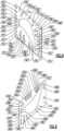
- the cooling holes 80 are individually designated by their three-letter codes in Figures 5, 6, 7 , 8, 9 , 10, and 11 .
- Figures 5 and 6 depict the second side 72d of the airfoil section 72, and Figures 10 and 11 depict edges of the outer platform 70b.
- Figure 8 depicts the outer platform 70b and Figure 9 depicts the inner platform 70a.
- Figure 7 depicts a cross-section through the airfoil section 72.
- the body vane 60a includes cooling holes 80 that have external breakout points 80a located in accordance with Cartesian coordinates of at least points 1 through 11, 193 through 201, and 268 through 275 set forth in Table 1 below.
- the body vane 60a also includes cooling holes 80 with external breakout points 80a located in accordance with Cartesian coordinates of points 12 through 55 set forth in Table 1.
- the body vane 60a also includes cooling holes 80 with external breakout points 80a located in accordance with Cartesian coordinates of points 56 through 102 set forth in Table 1.
- the body vane 60a also includes cooling holes 80 with external breakout points 80a located in accordance with Cartesian coordinates of points 103 through 192 set forth in Table 1.
- the body vane 60a also includes cooling holes 80 with external breakout points 80a located in accordance with Cartesian coordinates of points 202 through 267 set forth in Table 1. In an additional example, the body vane 60a also includes cooling holes 80 with external breakout points 80a located in accordance with Cartesian coordinates of points 276 through 293 set forth in Table 1.
- Cartesian coordinates of Table 1 may additionally or alternatively be equivalently represented with respect to one or more origin points other than the reference-coordinate 82.
- the Cartesian coordinates of Table 1 represent a spatial arrangement of the breakout points 80a of the cooling holes 80. The locations of the breakout points 80a in that spatial arrangement relative to one another are fixed, regardless of the location of the selected origin point.
- Conformance in accordance with the coordinates of Table 1 is based on points representing the locations of the breakout points 80a of the cooling holes 80, for example in inches.
- a conforming turbine airfoil has cooling holes with breakout points located in accordance with the specified sets of points, within the tolerance circle.
- Conformance can alternatively be based on a determination by a national or international regulatory body, for example in a part certification or part manufacture approval (PMA) process for the Federal Aviation Administration, the European Aviation Safety Agency, the Civil Aviation Administration of China, the Japan Civil Aviation Bureau, or the Russian Federal Agency for Air Transport.
- PMA part certification or part manufacture approval
- conformance encompasses a determination that a particular part or structure is identical to, or sufficiently similar to, the specified turbine airfoil, or that the part or structure is sufficiently the same with respect to a part design in a type-certified or type-certificated turbine airfoil, such that the part or structure complies with airworthiness standards applicable to the specified turbine airfoil.
- conformance encompasses any regulatory determination that a particular part or structure is sufficiently similar to, identical to, or the same as a specified turbine airfoil, such that certification or authorization for use is based at least in part on the determination of similarity.
Landscapes
- Engineering & Computer Science (AREA)
- Mechanical Engineering (AREA)
- General Engineering & Computer Science (AREA)
- Physics & Mathematics (AREA)
- Fluid Mechanics (AREA)
- Turbine Rotor Nozzle Sealing (AREA)
Abstract
Description
- Gas turbine engines typically include a compressor section, a combustor section and a turbine section. During operation, air is pressurized in the compressor section and is mixed with fuel and burned in the combustor section to generate hot combustion gases. The hot combustion gases are communicated through the turbine section, which extracts energy from the hot combustion gases to power the compressor section and other gas turbine engine loads.
- Both the compressor and turbine sections may include alternating series of rotating blades and stationary vanes that extend into the core flow path of the gas turbine engine. For example, in the turbine section, turbine blades rotate and extract energy from the hot combustion gases that are communicated along the core flow path of the gas turbine engine. The turbine vanes, which generally do not rotate, guide the airflow for the next set of blades. The turbine vanes include one or more airfoils that radially extend between inner and outer platforms or endwalls. Blades and vanes are generally referred to as "airfoils."
- Turbine vanes and blades can include cooling features to provide a boundary layer of cooling fluid along external surfaces, which protects the airfoil from the hot combustion gases in the core flow path. Non-linear flow analyses and complex strain modeling are required to achieve good cooling, making practical results difficult to predict. Loading and temperature considerations also impose substantial design limitations, which cannot easily be generalized from one system to another.
- A turbine airfoil according to an example of the present disclosure includes a body that has inner and outer platforms and an airfoil section that extends between the inner and outer platforms, and cooling holes that define external breakout points from the body. The external breakout points are located in accordance with Cartesian coordinates of at least points 1 through 11, 193 through 201, and 268 through 275 set forth in Table 1.
- In a further embodiment of any of the foregoing embodiments, the cooling holes having external breakout points in accordance with Cartesian coordinates of points 12 through 55 set forth in Table 1.
- In a further embodiment of any of the foregoing embodiments, the cooling holes having external breakout points in accordance with Cartesian coordinates of points 56 through 102 set forth in Table 1.
- In a further embodiment of any of the foregoing embodiments, the cooling holes having external breakout points in accordance with Cartesian coordinates of points 103 through 192 set forth in Table 1.
- In a further embodiment of any of the foregoing embodiments, the cooling holes having external breakout points in accordance with Cartesian coordinates of points 202 through 267 set forth in Table 1.
- In a further embodiment of any of the foregoing embodiments, the cooling holes having external breakout points in accordance with Cartesian coordinates of points 276 through 293 set forth in Table 1.
- A gas turbine engine according to an example of the present disclosure includes a compressor section, a combustor, and a turbine section. The turbine section has an array of turbine airfoils as in any of the foregoing embodiments.
- In a further embodiment of any of the foregoing embodiments, the cooling holes having external breakout points in accordance with Cartesian coordinates of points 12 through 55 set forth in Table 1.
- In a further embodiment of any of the foregoing embodiments, the cooling holes having external breakout points in accordance with Cartesian coordinates of points 56 through 102 set forth in Table 1.
- In a further embodiment of any of the foregoing embodiments, the cooling holes having external breakout points in accordance with Cartesian coordinates of points 103 through 192 set forth in Table 1.
- In a further embodiment of any of the foregoing embodiments, the cooling holes having external breakout points in accordance with Cartesian coordinates of points 202 through 267 set forth in Table 1.
- In a further embodiment of any of the foregoing embodiments, the cooling holes having external breakout points in accordance with Cartesian coordinates of points 276 through 293 set forth in Table 1.
- A turbine airfoil according to an example of the present disclosure includes a body having inner and outer platforms and an airfoil section extending between the inner and outer platforms and cooling holes that define external breakout points from the body. The external breakout points are located in accordance with Cartesian coordinates of at least points 1 through 11 and 193 through 201 set forth in Table 1.
- In a further embodiment of any of the foregoing embodiments, the cooling holes having external breakout points in accordance with Cartesian coordinates of points 12 through 55 set forth in Table 1.
- In a further embodiment of any of the foregoing embodiments, the cooling holes having external breakout points in accordance with Cartesian coordinates of points 56 through 102 set forth in Table 1.
- In a further embodiment of any of the foregoing embodiments, the cooling holes having external breakout points in accordance with Cartesian coordinates of points 103 through 146 set forth in Table 1.
- In a further embodiment of any of the foregoing embodiments, the cooling holes having external breakout points in accordance with Cartesian coordinates of points 147 through 192 set forth in Table 1.
- In a further embodiment of any of the foregoing embodiments, the cooling holes having external breakout points in accordance with Cartesian coordinates of points 268 through 275 set forth in Table 1.
- In a further embodiment of any of the foregoing embodiments, the cooling holes having external breakout points in accordance with Cartesian coordinates of points 202 through 267 set forth in Table 1.
- In a further embodiment of any of the foregoing embodiments, the cooling holes having external breakout points in accordance with Cartesian coordinates of points 276 through 293 set forth in Table 1.
- The present disclosure may include any one or more of the individual features disclosed above and/or below alone or in any combination thereof.
- The various features and advantages of the present disclosure will become apparent to those skilled in the art from the following detailed description. The drawings that accompany the detailed description can be briefly described as follows.
-
Figure 1 illustrates an example gas turbine engine. -
Figure 2 illustrates selected portions of a high pressure turbine of the gas turbine engine. -
Figure 3 illustrates an isolated view of a representative turbine airfoil of the high pressure turbine. -
Figure 4 illustrates a representative cooling hole. -
Figure 5 illustrates a portion of the airfoil section of the turbine airfoil ofFigure 3 . -
Figure 6 illustrates another portion of the airfoil section of the turbine airfoil ofFigure 3 . -
Figure 7 illustrates a section through the airfoil section of the turbine airfoil ofFigure 3 . -
Figure 8 illustrates the gas-path surface of the outer platform of the turbine airfoil ofFigure 3 . -
Figure 9 illustrates the gas-path surface of the inner platform of the turbine airfoil ofFigure 3 . -
Figure 10 illustrates another portion of the outer platform of the turbine airfoil ofFigure 3 . -
Figure 11 illustrates another portion of the outer platform of the turbine airfoil ofFigure 3 . -
Figure 1 schematically illustrates agas turbine engine 20. Thegas turbine engine 20 is disclosed herein as a two-spool turbofan that generally incorporates afan section 22, acompressor section 24, a combustor section 26 and aturbine section 28. Thefan section 22 drives air along a bypass flow path B in a bypass duct defined within ahousing 15 such as a fan case or nacelle, and also drives air along a core flow path C for compression in thecompressor section 24 and communication into the combustor section 26 then expansion through theturbine section 28. Although depicted as a two-spool turbofan gas turbine engine in the disclosed non-limiting embodiment, it should be understood that the concepts described herein are not limited to use with two-spool turbofans as the teachings may be applied to other types of turbine engines including three-spool architectures. - The
exemplary engine 20 generally includes alow speed spool 30 and ahigh speed spool 32 mounted for rotation about an engine central longitudinal axis A relative to an enginestatic structure 36 viaseveral bearing systems 38. It should be understood thatvarious bearing systems 38 at various locations may alternatively or additionally be provided, and the location ofbearing systems 38 may be varied as appropriate to the application. - The
low speed spool 30 generally includes aninner shaft 40 that interconnects, a first (or low)pressure compressor 44 and a first (or low)pressure turbine 46. Theinner shaft 40 is connected to the fan 42 through a speed change mechanism, which in exemplarygas turbine engine 20 is illustrated as a gearedarchitecture 48 to drive a fan 42 at a lower speed than thelow speed spool 30. Thehigh speed spool 32 includes anouter shaft 50 that interconnects a second (or high)pressure compressor 52 and a second (or high)pressure turbine 54. A combustor 56 is arranged in theexemplary gas turbine 20 between thehigh pressure compressor 52 and thehigh pressure turbine 54. A mid-turbine frame 57 of the enginestatic structure 36 may be arranged generally between thehigh pressure turbine 54 and thelow pressure turbine 46. The mid-turbine frame 57 further supports bearingsystems 38 in theturbine section 28. Theinner shaft 40 and theouter shaft 50 are concentric and rotate viabearing systems 38 about the engine central longitudinal axis A which is collinear with their longitudinal axes. - The core airflow is compressed by the
low pressure compressor 44 then thehigh pressure compressor 52, mixed and burned with fuel in the combustor 56, then expanded through thehigh pressure turbine 54 andlow pressure turbine 46. The mid-turbine frame 57 includesairfoils 59 which are in the core airflow path C. Theturbines low speed spool 30 andhigh speed spool 32 in response to the expansion. It will be appreciated that each of the positions of thefan section 22,compressor section 24, combustor section 26,turbine section 28, and fandrive gear system 48 may be varied. For example,gear system 48 may be located aft of the low pressure compressor, or aft of the combustor section 26 or even aft ofturbine section 28, and fan 42 may be positioned forward or aft of the location ofgear system 48. - The
engine 20 in one example is a high-bypass geared aircraft engine. In a further example, theengine 20 bypass ratio is greater than about six (6), with an example embodiment being greater than about ten (10), and can be less than or equal to about 18.0, or more narrowly can be less than or equal to 16.0. The gearedarchitecture 48 is an epicyclic gear train, such as a planetary gear system or other gear system, with a gear reduction ratio of greater than about 2.3. The gear reduction ratio may be less than or equal to 4.0. Thelow pressure turbine 46 has a pressure ratio that is greater than about five. The low pressure turbine pressure ratio can be less than or equal to 13.0, or more narrowly less than or equal to 12.0. In one disclosed embodiment, theengine 20 bypass ratio is greater than about ten (10:1), the fan diameter is significantly larger than that of thelow pressure compressor 44, and thelow pressure turbine 46 has a pressure ratio that is greater than about five 5:1.Low pressure turbine 46 pressure ratio is pressure measured prior to an inlet oflow pressure turbine 46 as related to the pressure at the outlet of thelow pressure turbine 46 prior to an exhaust nozzle. The gearedarchitecture 48 may be an epicycle gear train, such as a planetary gear system or other gear system, with a gear reduction ratio of greater than about 2.3:1 and less than about 5:1. It should be understood, however, that the above parameters are only exemplary of one embodiment of a geared architecture engine and that the present invention is applicable to other gas turbine engines including direct drive turbofans. - A significant amount of thrust is provided by the bypass flow B due to the high bypass ratio. The
fan section 22 of theengine 20 is designed for a particular flight condition -- typically cruise at about 0.8 Mach and about 35,000 feet (10,668 meters). The flight condition of 0.8 Mach and 35,000 ft (10,668 meters), with the engine at its best fuel consumption - also known as "bucket cruise Thrust Specific Fuel Consumption ('TSFC')" - is the industry standard parameter of lbm of fuel being burned divided by lbf of thrust the engine produces at that minimum point. The engine parameters described above and those in this paragraph are measured at this condition unless otherwise specified. "Low fan pressure ratio" is the pressure ratio across the fan blade alone, without a Fan Exit Guide Vane ("FEGV") system. The low fan pressure ratio as disclosed herein according to one non-limiting embodiment is less than about 1.45, or more narrowly greater than or equal to 1.25. "Low corrected fan tip speed" is the actual fan tip speed in ft/sec divided by an industry standard temperature correction of [(Tram °R) / (518.7 °R)]0.5 (where °R = K x 9/5). The "Low corrected fan tip speed" as disclosed herein according to one non-limiting embodiment is less than about 1150.0 ft / second (350.5 meters/second), and can be greater than or equal to 1000.0 ft / second (304.8 meters/second). -
Figure 2 illustrates a cross-sectional view of a portion of the highpressure turbine section 54. The highpressure turbine section 54 includes first andsecond arrays 54a/54c of circumferentially spaced fixedvanes 60/62 (turbine airfoils). Thearrays 54a/54c are axially spaced apart from one another. Afirst stage array 54b of circumferentially spacedturbine blades 64, mounted to arotor disk 68, is arranged axially between the first and second fixedvane arrays 54a/54c. Asecond stage array 54d of circumferentially spacedturbine blades 66 is arranged aft of thesecond array 54c of fixedvanes 62. -
Figure 3 shows an isolated view of a representative one of thevanes 60. Thevane 60 includes avane body 60a that includes at least inner andouter platforms 70a/70b and anairfoil section 72 that extends between theplatforms 70a/70b. Theairfoil section 72 includes leading and trailingedges 72a/72b that are joined by spaced apart first andsecond sides 72c/72d to provide an exterior airfoil surface. For example, thefirst side 72c is a suction side and thesecond side 72d is a pressure side. - The
vane 60 may be formed of a high strength, heat resistant material, such as, but not limited to, a nickel-based or cobalt-based superalloy. In cooled configurations, internal fluid passages and external cooling apertures provide for a combination of convection and cooling. In addition, one or more thermal barrier coatings, abrasion-resistant coatings or other protective coatings may be applied to thevane 60, or at least portions thereof. - The
vane 60 includes cooling holes 80. The cooling holes 80 are in fluid communication with cooling passages (not shown) within thevane 60. Generally, cooling air is bled from thecompressor section 24 and fed into the cooling passages. The cooling air absorbs heat from internal surfaces in thevane 60 and is then discharged from thevane 60 through the cooling holes 80 to provide a film of cooling air across the exterior surfaces of thevane 60. The cooling holes 80 are located on theplatforms 70a/70b andairfoil section 72. -
Figure 4 illustrates a representative example of one of the cooling holes 80. Each coolinghole 80 defines an externalbreakout point 80a from thevane body 60a. For instance, the externalbreakout point 80a is in the plane of or flush with the exterior surface of thevane body 60a. In the illustrated example, thecooling hole 80 is a divergent hole that is defined bydivergent sides 80b/80c and asloped bottom 80d. Thecooling hole 80 defines a hole centerline, CL, that intersects the externalbreakout point 80a. For example, the centerline CL intersects the externalbreakout point 80a, and thedivergent sides 80b/80c may diverge at a half-angle of 10° relative to the centerline CL. The angles may vary within a tolerance of +/- 2°, but in additional examples the angles vary within +/- 1° or within +/- 0.5°. - The
external breakout points 80a of the cooling holes 80 are located in accordance with Cartesian coordinates of points, or at least selected sets of points prescribed herein, set forth in Table 1 below. Referring toFigure 3 , the Cartesian coordinates are provided by an axial coordinate (X-coordinate), a circumferential coordinate (Y-coordinate), and a radial coordinate (Z-coordinate), relative to an origin point, which here is designated as reference-coordinate 82. The axial coordinate is along a direction parallel to the engine axis A, and is positive in the aft direction. The radial coordinate is along a direction perpendicular to the engine axis A, and is positive in a radially outwardly direction. The circumferential coordinate is along a circumferential direction about the engine axis A, and is positive consistent with a right-handed coordinate system. - In the illustrated example, the reference-coordinate 82 is taken with respect to a
hole 84 on atab 86 of thevane 60. Thetab 86 extends radially inwards from theinner platform 70a of thevane 60, and a forward surface 86a of thetab 86 is substantially flush with a forward side of theinner platform 70a. The reference-point 82 is located at the centerpoint of thehole 84 flush with the forward surface 86a of thetab 86. - The coordinates of Table 1 (in inches) provide the nominal axial, circumferential, and radial coordinates relative to the reference-coordinate 82, on a cold, coated (with a metallic bondcoat of a nominal thickness that is substantially less than the tolerance of the cooling holes 80),
stationary vane 60. As will be appreciated, the coordinates can equivalently be expressed in units other than inches, such as millimeters. Each row in Table 1 corresponds to asingle cooling hole 80 and location of its externalbreakout point 80a from thevane body 60a. - The exact locations of the
external breakout points 80a vary within a defined spatial envelope in order to account for manufacturing variations. The spatial envelope is a tolerance circle on the surface of thevane body 60a about the given coordinate. Herein, each externalbreakout point 80a in Table 1 is within a 0.100 inch (2.54 mm) diameter tolerance circle about the given Cartesian coordinate. That is, the given Cartesian coordinate is the centerpoint of the tolerance circle on the surface of thevane body 60a and the actual location of the corresponding externalbreakout point 80a lies within the tolerance circle. In further examples, the tolerance is tighter and the externalbreakout point 80a is within a 0.05 inch (1.27 mm), or even a 0.01 inch (0.254 mm), diameter tolerance circle about the given Cartesian coordinate in Table 1. - As discussed above, the cooling holes 80 are located in accordance with Cartesian coordinates of points, or at least selected sets of points prescribed herein, set forth in Table 1 below. Each numbered point in Table 1 is designated with a unique three-letter code that identifies each
individual cooling hole 80. The first two letters of the three-letter code designate a row and the last letter designates the hole of that row (e.g., holes TBA, TBB, and TBC refer to holes A through C in the hole cluster TB). The cooling holes 80 are individually designated by their three-letter codes inFigures 5, 6, 7 ,8, 9 ,10, and 11 .Figures 5 and 6 depict thesecond side 72d of theairfoil section 72, andFigures 10 and 11 depict edges of theouter platform 70b.Figure 8 depicts theouter platform 70b andFigure 9 depicts theinner platform 70a.Figure 7 depicts a cross-section through theairfoil section 72. - The
body vane 60a includes cooling holes 80 that have externalbreakout points 80a located in accordance with Cartesian coordinates of at least points 1 through 11, 193 through 201, and 268 through 275 set forth in Table 1 below. In an additional example, thebody vane 60a also includes cooling holes 80 with externalbreakout points 80a located in accordance with Cartesian coordinates of points 12 through 55 set forth in Table 1. In an additional example, thebody vane 60a also includes cooling holes 80 with externalbreakout points 80a located in accordance with Cartesian coordinates of points 56 through 102 set forth in Table 1. In an additional example, thebody vane 60a also includes cooling holes 80 with externalbreakout points 80a located in accordance with Cartesian coordinates of points 103 through 192 set forth in Table 1. In an additional example, thebody vane 60a also includes cooling holes 80 with externalbreakout points 80a located in accordance with Cartesian coordinates of points 202 through 267 set forth in Table 1. In an additional example, thebody vane 60a also includes cooling holes 80 with externalbreakout points 80a located in accordance with Cartesian coordinates of points 276 through 293 set forth in Table 1. - It is to be further appreciated that the Cartesian coordinates of Table 1 may additionally or alternatively be equivalently represented with respect to one or more origin points other than the reference-coordinate 82. The Cartesian coordinates of Table 1 represent a spatial arrangement of the breakout points 80a of the cooling holes 80. The locations of the
breakout points 80a in that spatial arrangement relative to one another are fixed, regardless of the location of the selected origin point.TABLE 1 (within 0.100 inch or 0.05 inch diameter tolerance circle) Hole #: Code: X: Y: Z: 1 HAA 0.380 0.471 0.984 2 HAB 0.394 0.464 1.116 3 HAC 0.397 0.464 1.250 4 HAD 0.399 0.463 1.384 5 HAE 0.398 0.462 1.517 6 HAF 0.400 0.462 1.651 7 HAG 0.400 0.463 1.785 8 HAH 0.400 0.463 1.919 9 HAJ 0.399 0.464 2.052 10 HAK 0.398 0.465 2.186 11 HAL 0.396 0.466 2.320 12 HBA 0.318 0.422 0.907 13 HBB 0.348 0.405 1.029 14 HBC 0.350 0.404 1.166 15 HBD 0.351 0.404 1.308 16 HBE 0.352 0.405 1.451 17 HBF 0.352 0.405 1.578 18 HBG 0.352 0.404 1.643 19 HBH 0.352 0.405 1.709 20 HBJ 0.352 0.405 1.837 21 HBK 0.352 0.405 1.978 22 HBL 0.352 0.406 2.120 23 HBM 0.353 0.410 2.271 24 HCA 0.305 0.327 0.928 25 HCB 0.323 0.324 1.079 26 HCC 0.323 0.325 1.244 27 HCD 0.323 0.325 1.405 28 HCE 0.323 0.326 1.529 29 HCF 0.323 0.326 1.644 30 HCG 0.323 0.326 1.763 31 HCH 0.323 0.325 1.935 32 HCJ 0.323 0.325 2.095 33 HCK 0.323 0.326 2.251 34 HDA 0.319 0.245 0.978 35 HDB 0.323 0.243 1.150 36 HDC 0.323 0.239 1.313 37 HDD 0.323 0.239 1.456 38 HDE 0.325 0.233 1.578 39 HDF 0.325 0.232 1.722 40 HDG 0.323 0.240 1.867 41 HDH 0.323 0.243 2.003 42 HDJ 0.322 0.246 2.163 43 HDK 0.322 0.246 2.296 44 HEA 0.312 0.144 0.856 45 HEB 0.344 0.165 0.962 46 HEC 0.347 0.167 1.100 47 HED 0.348 0.168 1.241 48 HEE 0.348 0.168 1.329 49 HEF 0.348 0.169 1.409 50 HEG 0.348 0.169 1.538 51 HEH 0.349 0.169 1.640 52 HEJ 0.349 0.169 1.768 53 HEK 0.348 0.169 1.910 54 HEL 0.350 0.165 2.053 55 HEM 0.353 0.159 2.194 56 PAA 1.130 1.355 0.958 57 PAA 1.138 1.392 1.042 58 PAA 1.145 1.425 1.126 59 PAA 1.150 1.454 1.210 60 PAA 1.155 1.478 1.294 61 PAA 1.159 1.498 1.379 62 PAA 1.161 1.514 1.463 63 PAA 1.163 1.525 1.547 64 PAA 1.163 1.532 1.631 65 PAA 1.163 1.534 1.715 66 PAA 1.161 1.531 1.800 67 PAA 1.159 1.525 1.884 68 PAA 1.155 1.514 1.968 69 PAA 1.150 1.499 2.053 70 PAA 1.145 1.479 2.137 71 PAB 1.145 1.470 2.221 72 PBA 1.069 1.242 0.961 73 PBA 1.072 1.282 1.133 74 PBA 1.075 1.312 1.296 75 PBA 1.077 1.336 1.462 76 PBA 1.079 1.354 1.625 77 PBA 1.081 1.367 1.788 78 PBA 1.083 1.373 1.953 79 PBA 1.085 1.372 2.117 80 PBB 1.074 1.274 1.067 81 PBB 1.077 1.306 1.232 82 PBB 1.079 1.332 1.392 83 PBB 1.081 1.352 1.557 84 PBB 1.083 1.367 1.722 85 PBB 1.085 1.377 1.888 86 PBB 1.087 1.379 2.044 87 PBB 1.089 1.373 2.200 88 PCA 0.901 0.993 0.992 89 PCA 0.900 1.007 1.136 90 PCA 0.897 1.018 1.321 91 PCA 0.894 1.024 1.486 92 PCA 0.890 1.029 1.650 93 PCA 0.887 1.032 1.814 94 PCA 0.883 1.034 1.977 95 PCA 0.879 1.034 2.140 96 PCB 0.899 1.015 1.249 97 PCB 0.896 1.023 1.410 98 PCB 0.892 1.028 1.577 99 PCB 0.888 1.031 1.743 100 PCB 0.885 1.033 1.906 101 PCB 0.880 1.034 2.070 102 PCB 0.876 1.033 2.231 103 PDA 0.695 0.749 1.032 104 PDA 0.690 0.744 1.127 105 PDA 0.684 0.739 1.223 106 PDA 0.679 0.734 1.318 107 PDB 0.678 0.735 1.474 108 PDB 0.674 0.731 1.565 109 PDB 0.669 0.727 1.656 110 PDB 0.665 0.723 1.746 111 PDB 0.660 0.720 1.836 112 PDB 0.656 0.718 1.926 113 PDB 0.652 0.716 2.015 114 PDB 0.648 0.715 2.105 115 PDB 0.644 0.715 2.193 116 PDB 0.640 0.716 2.282 117 PEA 0.563 0.616 1.058 118 PEA 0.563 0.613 1.141 119 PEA 0.562 0.612 1.225 120 PEA 0.562 0.610 1.309 121 PEA 0.562 0.609 1.392 122 PEA 0.563 0.608 1.477 123 PEA 0.563 0.608 1.561 124 PEA 0.564 0.609 1.645 125 PEB 0.564 0.610 1.782 126 PEB 0.561 0.608 1.870 127 PEB 0.558 0.607 1.957 128 PEB 0.555 0.606 2.044 129 PEB 0.553 0.606 2.130 130 PEB 0.551 0.607 2.216 131 PEB 0.549 0.609 2.301 132 PFA 0.477 0.544 1.039 133 PFA 0.479 0.538 1.123 134 PFA 0.480 0.537 1.213 135 PFA 0.482 0.536 1.303 136 PFA 0.484 0.535 1.394 137 PFB 0.489 0.538 1.532 138 PFB 0.488 0.535 1.616 139 PFB 0.487 0.534 1.700 140 PFB 0.485 0.532 1.784 141 PFB 0.484 0.532 1.867 142 PFB 0.483 0.531 1.950 143 PFB 0.482 0.531 2.032 144 PFB 0.481 0.532 2.114 145 PFB 0.479 0.533 2.196 146 PFB 0.478 0.535 2.277 147 SAA 0.446 0.055 0.951 148 SAA 0.446 0.059 1.039 149 SAA 0.446 0.063 1.128 150 SAA 0.445 0.066 1.218 151 SAB 0.444 0.070 1.338 152 SAB 0.444 0.071 1.424 153 SAB 0.444 0.072 1.510 154 SAB 0.444 0.073 1.595 155 SAB 0.444 0.073 1.680 156 SAB 0.445 0.073 1.765 157 SAB 0.445 0.073 1.849 158 SAB 0.445 0.072 1.933 159 SAB 0.445 0.071 2.016 160 SAB 0.446 0.069 2.100 161 SAB 0.446 0.067 2.182 162 SAB 0.446 0.065 2.265 163 SBA 0.556 0.020 0.972 164 SBA 0.555 0.023 1.051 165 SBA 0.554 0.025 1.130 166 SBA 0.554 0.027 1.209 167 SBA 0.554 0.029 1.289 168 SBA 0.554 0.031 1.369 169 SBA 0.554 0.032 1.450 170 SBA 0.554 0.033 1.531 171 SBB 0.555 0.034 1.641 172 SBB 0.554 0.034 1.721 173 SBB 0.552 0.035 1.800 174 SBB 0.551 0.035 1.880 175 SBB 0.550 0.034 1.959 176 SBB 0.549 0.034 2.038 177 SBB 0.548 0.033 2.117 178 SBB 0.547 0.032 2.195 179 SBB 0.547 0.030 2.273 180 SCA 0.773 0.117 1.103 181 SCA 0.775 0.117 1.185 182 SCA 0.776 0.117 1.267 183 SCA 0.777 0.118 1.350 184 SCA 0.778 0.118 1.433 185 SCA 0.779 0.119 1.517 186 SCA 0.779 0.119 1.600 187 SCA 0.779 0.119 1.684 188 SCA 0.778 0.120 1.769 189 SCA 0.777 0.120 1.853 190 SCA 0.776 0.121 1.938 191 SCA 0.774 0.122 2.024 192 SCA 0.772 0.122 2.109 193 SDA 0.932 0.333 1.097 194 SDA 0.932 0.330 1.230 195 SDA 0.932 0.325 1.363 196 SDA 0.930 0.320 1.495 197 SDA 0.926 0.314 1.626 198 SDB 0.921 0.308 1.758 199 SDB 0.914 0.300 1.891 200 SDB 0.905 0.291 2.024 201 SDB 0.894 0.281 2.158 202 HFA 0.277 0.492 0.818 203 HFB 0.241 0.377 0.812 204 HFC 0.238 0.242 0.805 205 HFD 0.275 0.124 0.800 206 HHA 0.231 0.581 0.764 207 HHB 0.155 0.451 0.742 208 HHC 0.149 0.274 0.738 209 HHD 0.157 0.100 0.722 210 HHE 0.165 -0.073 0.707 211 RAA 0.133 -0.438 0.653 212 RAB 0.143 -0.269 0.679 213 RAC 0.271 -0.308 0.704 214 RAD 0.283 -0.101 0.731 215 RAE 0.420 -0.167 0.756 216 RAF 0.404 -0.038 0.773 217 RAG 0.567 -0.031 0.816 218 RBA 0.953 1.184 0.844 219 RBB 1.044 1.274 0.844 220 RCA 0.890 1.209 0.840 221 RCB 0.983 1.296 0.831 222 RCC 1.081 1.367 0.828 223 RDA 1.335 1.391 0.821 224 RDB 1.340 1.570 0.797 225 REA 0.631 0.920 0.836 226 REB 0.626 1.024 0.829 227 RFA 0.514 0.825 0.815 228 RFB 0.495 0.917 0.805 229 RGA 0.403 0.731 0.800 230 RGB 0.368 0.808 0.780 231 RHA 0.930 0.233 0.868 232 RHB 1.010 0.326 0.866 233 RHC 1.096 0.432 0.868 234 RJA 1.339 0.862 0.864 235 HGA 0.341 0.437 2.450 236 HGB 0.321 0.348 2.422 237 HGC 0.320 0.234 2.415 238 HGD 0.366 0.124 2.414 239 HJA 0.198 0.409 2.514 240 HJB 0.195 0.233 2.510 241 HJC 0.201 0.073 2.500 242 TAA 1.104 1.605 2.305 243 TAB 1.041 1.481 2.331 244 TBA 0.914 1.457 2.355 245 TBB 0.883 1.296 2.376 246 TCA 0.605 1.196 2.433 247 TCB 0.601 1.068 2.442 248 TCC 0.598 0.920 2.450 249 TDA 0.417 1.030 2.477 250 TDB 0.418 0.863 2.485 251 TDC 0.418 0.713 2.488 252 TFA 0.202 0.878 2.508 253 TFB 0.202 0.728 2.512 254 TFC 0.203 0.570 2.513 255 TGA 0.200 -0.068 2.490 256 TGB 0.204 -0.274 2.471 257 TGC 0.204 -0.487 2.447 258 THA 0.370 -0.341 2.448 259 THB 0.493 -0.219 2.439 260 THC 0.444 -0.064 2.461 261 TKA 0.827 0.038 2.401 262 TLA 1.063 0.215 2.370 263 TLB 1.257 0.378 2.344 264 TLC 1.057 0.367 2.376 265 TMA 1.427 0.547 2.347 266 TMB 1.304 0.669 2.343 267 TMC 1.186 0.653 2.354 268 TNA 1.457 0.860 2.344 269 TNB 1.339 0.906 2.337 270 TNC 1.235 0.896 2.341 271 TPA 1.443 1.048 2.334 272 TPB 1.435 1.235 2.321 273 TPC 1.319 1.129 2.325 274 TRA 1.427 1.422 2.303 275 TRB 1.338 1.375 2.304 276 TSA 1.447 1.657 2.276 277 TSB 1.343 1.609 2.278 278 TTA 1.408 1.803 2.253 279 TUA 1.424 0.395 2.385 280 TUB 1.319 0.307 2.386 281 TUC 1.220 0.224 2.385 282 TUD 0.785 -0.141 2.436 283 TVA 1.562 1.433 2.375 284 TVB 1.562 1.528 2.366 285 TVC 1.562 1.622 2.356 286 TVD 1.562 1.717 2.345 287 TVE 1.562 1.812 2.333 288 TWA 1.332 1.924 2.281 289 TWB 1.232 1.842 2.302 290 TWC 1.048 1.695 2.352 291 TWD 0.839 1.527 2.407 292 TWE 0.635 1.362 2.455 293 TWF 0.221 1.030 2.565 - Conformance in accordance with the coordinates of Table 1 is based on points representing the locations of the breakout points 80a of the cooling holes 80, for example in inches. A conforming turbine airfoil has cooling holes with breakout points located in accordance with the specified sets of points, within the tolerance circle.
- Conformance can alternatively be based on a determination by a national or international regulatory body, for example in a part certification or part manufacture approval (PMA) process for the Federal Aviation Administration, the European Aviation Safety Agency, the Civil Aviation Administration of China, the Japan Civil Aviation Bureau, or the Russian Federal Agency for Air Transport. In these configurations, conformance encompasses a determination that a particular part or structure is identical to, or sufficiently similar to, the specified turbine airfoil, or that the part or structure is sufficiently the same with respect to a part design in a type-certified or type-certificated turbine airfoil, such that the part or structure complies with airworthiness standards applicable to the specified turbine airfoil. In particular, conformance encompasses any regulatory determination that a particular part or structure is sufficiently similar to, identical to, or the same as a specified turbine airfoil, such that certification or authorization for use is based at least in part on the determination of similarity.
- Although a combination of features is shown in the illustrated examples, not all of them need to be combined to realize the benefits of various embodiments of this disclosure. In other words, a system designed according to an embodiment of this disclosure will not necessarily include all of the features shown in any one of the Figures or all of the portions schematically shown in the Figures. Moreover, selected features of one example embodiment may be combined with selected features of other example embodiments.
- The preceding description is exemplary rather than limiting in nature. Variations and modifications to the disclosed examples may become apparent to those skilled in the art that do not necessarily depart from the essence of this disclosure. The scope of legal protection given to this disclosure can only be determined by studying the following claims.
Claims (9)
- A turbine airfoil (60) comprising:a body (60a) having inner and outer platforms (70a, 70b) and an airfoil section (72) extending between the inner and outer platforms (70a, 70b); andcooling holes (80) that define external breakout points (80a) from the body (60a), the external breakout points (80a) being located in accordance with Cartesian coordinates of at least points 1 through 11 and 193 through 201 set forth in Table 1:
Hole #: Code: X: Y: Z: 1 HAA 0.380 0.471 0.984 2 HAB 0.394 0.464 1.116 3 HAC 0.397 0.464 1.250 4 HAD 0.399 0.463 1.384 5 HAE 0.398 0.462 1.517 6 HAF 0.400 0.462 1.651 7 HAG 0.400 0.463 1.785 8 HAH 0.400 0.463 1.919 9 HAJ 0.399 0.464 2.052 10 HAK 0.398 0.465 2.186 11 HAL 0.396 0.466 2.320 12 HBA 0.318 0.422 0.907 13 HBB 0.348 0.405 1.029 14 HBC 0.350 0.404 1.166 15 HBD 0.351 0.404 1.308 16 HBE 0.352 0.405 1.451 17 HBF 0.352 0.405 1.578 18 HBG 0.352 0.404 1.643 19 HBH 0.352 0.405 1.709 20 HBJ 0.352 0.405 1.837 21 HBK 0.352 0.405 1.978 22 HBL 0.352 0.406 2.120 23 HBM 0.353 0.410 2.271 24 HCA 0.305 0.327 0.928 25 HCB 0.323 0.324 1.079 26 HCC 0.323 0.325 1.244 27 HCD 0.323 0.325 1.405 28 HCE 0.323 0.326 1.529 29 HCF 0.323 0.326 1.644 30 HCG 0.323 0.326 1.763 31 HCH 0.323 0.325 1.935 32 HCJ 0.323 0.325 2.095 33 HCK 0.323 0.326 2.251 34 HDA 0.319 0.245 0.978 35 HDB 0.323 0.243 1.150 36 HDC 0.323 0.239 1.313 37 HDD 0.323 0.239 1.456 38 HDE 0.325 0.233 1.578 39 HDF 0.325 0.232 1.722 40 HDG 0.323 0.240 1.867 41 HDH 0.323 0.243 2.003 42 HDJ 0.322 0.246 2.163 43 HDK 0.322 0.246 2.296 44 HEA 0.312 0.144 0.856 45 HEB 0.344 0.165 0.962 46 HEC 0.347 0.167 1.100 47 HED 0.348 0.168 1.241 48 HEE 0.348 0.168 1.329 49 HEF 0.348 0.169 1.409 50 HEG 0.348 0.169 1.538 51 HEH 0.349 0.169 1.640 52 HEJ 0.349 0.169 1.768 53 HEK 0.348 0.169 1.910 54 HEL 0.350 0.165 2.053 55 HEM 0.353 0.159 2.194 56 PAA 1.130 1.355 0.958 57 PAA 1.138 1.392 1.042 58 PAA 1.145 1.425 1.126 59 PAA 1.150 1.454 1.210 60 PAA 1.155 1.478 1.294 61 PAA 1.159 1.498 1.379 62 PAA 1.161 1.514 1.463 63 PAA 1.163 1.525 1.547 64 PAA 1.163 1.532 1.631 65 PAA 1.163 1.534 1.715 66 PAA 1.161 1.531 1.800 67 PAA 1.159 1.525 1.884 68 PAA 1.155 1.514 1.968 69 PAA 1.150 1.499 2.053 70 PAA 1.145 1.479 2.137 71 PAB 1.145 1.470 2.221 72 PBA 1.069 1.242 0.961 73 PBA 1.072 1.282 1.133 74 PBA 1.075 1.312 1.296 75 PBA 1.077 1.336 1.462 76 PBA 1.079 1.354 1.625 77 PBA 1.081 1.367 1.788 78 PBA 1.083 1.373 1.953 79 PBA 1.085 1.372 2.117 80 PBB 1.074 1.274 1.067 81 PBB 1.077 1.306 1.232 82 PBB 1.079 1.332 1.392 83 PBB 1.081 1.352 1.557 84 PBB 1.083 1.367 1.722 85 PBB 1.085 1.377 1.888 86 PBB 1.087 1.379 2.044 87 PBB 1.089 1.373 2.200 88 PCA 0.901 0.993 0.992 89 PCA 0.900 1.007 1.136 90 PCA 0.897 1.018 1.321 91 PCA 0.894 1.024 1.486 92 PCA 0.890 1.029 1.650 93 PCA 0.887 1.032 1.814 94 PCA 0.883 1.034 1.977 95 PCA 0.879 1.034 2.140 96 PCB 0.899 1.015 1.249 97 PCB 0.896 1.023 1.410 98 PCB 0.892 1.028 1.577 99 PCB 0.888 1.031 1.743 100 PCB 0.885 1.033 1.906 101 PCB 0.880 1.034 2.070 102 PCB 0.876 1.033 2.231 103 PDA 0.695 0.749 1.032 104 PDA 0.690 0.744 1.127 105 PDA 0.684 0.739 1.223 106 PDA 0.679 0.734 1.318 107 PDB 0.678 0.735 1.474 108 PDB 0.674 0.731 1.565 109 PDB 0.669 0.727 1.656 110 PDB 0.665 0.723 1.746 111 PDB 0.660 0.720 1.836 112 PDB 0.656 0.718 1.926 113 PDB 0.652 0.716 2.015 114 PDB 0.648 0.715 2.105 115 PDB 0.644 0.715 2.193 116 PDB 0.640 0.716 2.282 117 PEA 0.563 0.616 1.058 118 PEA 0.563 0.613 1.141 119 PEA 0.562 0.612 1.225 120 PEA 0.562 0.610 1.309 121 PEA 0.562 0.609 1.392 122 PEA 0.563 0.608 1.477 123 PEA 0.563 0.608 1.561 124 PEA 0.564 0.609 1.645 125 PEB 0.564 0.610 1.782 126 PEB 0.561 0.608 1.870 127 PEB 0.558 0.607 1.957 128 PEB 0.555 0.606 2.044 129 PEB 0.553 0.606 2.130 130 PEB 0.551 0.607 2.216 131 PEB 0.549 0.609 2.301 132 PFA 0.477 0.544 1.039 133 PFA 0.479 0.538 1.123 134 PFA 0.480 0.537 1.213 135 PFA 0.482 0.536 1.303 136 PFA 0.484 0.535 1.394 137 PFB 0.489 0.538 1.532 138 PFB 0.488 0.535 1.616 139 PFB 0.487 0.534 1.700 140 PFB 0.485 0.532 1.784 141 PFB 0.484 0.532 1.867 142 PFB 0.483 0.531 1.950 143 PFB 0.482 0.531 2.032 144 PFB 0.481 0.532 2.114 145 PFB 0.479 0.533 2.196 146 PFB 0.478 0.535 2.277 147 SAA 0.446 0.055 0.951 148 SAA 0.446 0.059 1.039 149 SAA 0.446 0.063 1.128 150 SAA 0.445 0.066 1.218 151 SAB 0.444 0.070 1.338 152 SAB 0.444 0.071 1.424 153 SAB 0.444 0.072 1.510 154 SAB 0.444 0.073 1.595 155 SAB 0.444 0.073 1.680 156 SAB 0.445 0.073 1.765 157 SAB 0.445 0.073 1.849 158 SAB 0.445 0.072 1.933 159 SAB 0.445 0.071 2.016 160 SAB 0.446 0.069 2.100 161 SAB 0.446 0.067 2.182 162 SAB 0.446 0.065 2.265 163 SBA 0.556 0.020 0.972 164 SBA 0.555 0.023 1.051 165 SBA 0.554 0.025 1.130 166 SBA 0.554 0.027 1.209 167 SBA 0.554 0.029 1.289 168 SBA 0.554 0.031 1.369 169 SBA 0.554 0.032 1.450 170 SBA 0.554 0.033 1.531 171 SBB 0.555 0.034 1.641 172 SBB 0.554 0.034 1.721 173 SBB 0.552 0.035 1.800 174 SBB 0.551 0.035 1.880 175 SBB 0.550 0.034 1.959 176 SBB 0.549 0.034 2.038 177 SBB 0.548 0.033 2.117 178 SBB 0.547 0.032 2.195 179 SBB 0.547 0.030 2.273 180 SCA 0.773 0.117 1.103 181 SCA 0.775 0.117 1.185 182 SCA 0.776 0.117 1.267 183 SCA 0.777 0.118 1.350 184 SCA 0.778 0.118 1.433 185 SCA 0.779 0.119 1.517 186 SCA 0.779 0.119 1.600 187 SCA 0.779 0.119 1.684 188 SCA 0.778 0.120 1.769 189 SCA 0.777 0.120 1.853 190 SCA 0.776 0.121 1.938 191 SCA 0.774 0.122 2.024 192 SCA 0.772 0.122 2.109 193 SDA 0.932 0.333 1.097 194 SDA 0.932 0.330 1.230 195 SDA 0.932 0.325 1.363 196 SDA 0.930 0.320 1.495 197 SDA 0.926 0.314 1.626 198 SDB 0.921 0.308 1.758 199 SDB 0.914 0.300 1.891 200 SDB 0.905 0.291 2.024 201 SDB 0.894 0.281 2.158 202 HFA 0.277 0.492 0.818 203 HFB 0.241 0.377 0.812 204 HFC 0.238 0.242 0.805 205 HFD 0.275 0.124 0.800 206 HHA 0.231 0.581 0.764 207 HHB 0.155 0.451 0.742 208 HHC 0.149 0.274 0.738 209 HHD 0.157 0.100 0.722 210 HHE 0.165 -0.073 0.707 211 RAA 0.133 -0.438 0.653 212 RAB 0.143 -0.269 0.679 213 RAC 0.271 -0.308 0.704 214 RAD 0.283 -0.101 0.731 215 RAE 0.420 -0.167 0.756 216 RAF 0.404 -0.038 0.773 217 RAG 0.567 -0.031 0.816 218 RBA 0.953 1.184 0.844 219 RBB 1.044 1.274 0.844 220 RCA 0.890 1.209 0.840 221 RCB 0.983 1.296 0.831 222 RCC 1.081 1.367 0.828 223 RDA 1.335 1.391 0.821 224 RDB 1.340 1.570 0.797 225 REA 0.631 0.920 0.836 226 REB 0.626 1.024 0.829 227 RFA 0.514 0.825 0.815 228 RFB 0.495 0.917 0.805 229 RGA 0.403 0.731 0.800 230 RGB 0.368 0.808 0.780 231 RHA 0.930 0.233 0.868 232 RHB 1.010 0.326 0.866 233 RHC 1.096 0.432 0.868 234 RJA 1.339 0.862 0.864 235 HGA 0.341 0.437 2.450 236 HGB 0.321 0.348 2.422 237 HGC 0.320 0.234 2.415 238 HGD 0.366 0.124 2.414 239 HJA 0.198 0.409 2.514 240 HJB 0.195 0.233 2.510 241 HJC 0.201 0.073 2.500 242 TAA 1.104 1.605 2.305 243 TAB 1.041 1.481 2.331 244 TBA 0.914 1.457 2.355 245 TBB 0.883 1.296 2.376 246 TCA 0.605 1.196 2.433 247 TCB 0.601 1.068 2.442 248 TCC 0.598 0.920 2.450 249 TDA 0.417 1.030 2.477 250 TDB 0.418 0.863 2.485 251 TDC 0.418 0.713 2.488 252 TFA 0.202 0.878 2.508 253 TFB 0.202 0.728 2.512 254 TFC 0.203 0.570 2.513 255 TGA 0.200 -0.068 2.490 256 TGB 0.204 -0.274 2.471 257 TGC 0.204 -0.487 2.447 258 THA 0.370 -0.341 2.448 259 THB 0.493 -0.219 2.439 260 THC 0.444 -0.064 2.461 261 TKA 0.827 0.038 2.401 262 TLA 1.063 0.215 2.370 263 TLB 1.257 0.378 2.344 264 TLC 1.057 0.367 2.376 265 TMA 1.427 0.547 2.347 266 TMB 1.304 0.669 2.343 267 TMC 1.186 0.653 2.354 268 TNA 1.457 0.860 2.344 269 TNB 1.339 0.906 2.337 270 TNC 1.235 0.896 2.341 271 TPA 1.443 1.048 2.334 272 TPB 1.435 1.235 2.321 273 TPC 1.319 1.129 2.325 274 TRA 1.427 1.422 2.303 275 TRB 1.338 1.375 2.304 276 TSA 1.447 1.657 2.276 277 TSB 1.343 1.609 2.278 278 TTA 1.408 1.803 2.253 279 TUA 1.424 0.395 2.385 280 TUB 1.319 0.307 2.386 281 TUC 1.220 0.224 2.385 282 TUD 0.785 -0.141 2.436 283 TVA 1.562 1.433 2.375 284 TVB 1.562 1.528 2.366 285 TVC 1.562 1.622 2.356 286 TVD 1.562 1.717 2.345 287 TVE 1.562 1.812 2.333 288 TWA 1.332 1.924 2.281 289 TWB 1.232 1.842 2.302 290 TWC 1.048 1.695 2.352 291 TWD 0.839 1.527 2.407 292 TWE 0.635 1.362 2.455 293 TWF 0.221 1.030 2.565 - The turbine airfoil (60) as recited in claim 1, wherein the cooling holes (80) having external breakout points (80a) in accordance with Cartesian coordinates of points 12 through 55 set forth in Table 1.
- The turbine airfoil (60) as recited in claim 1 or 2, wherein the cooling holes (80) having external breakout points (80a) in accordance with Cartesian coordinates of points 56 through 102 set forth in Table 1.
- The turbine airfoil as recited in claim 1, 2 or 3, wherein the cooling holes (80) having external breakout points (80a) in accordance with Cartesian coordinates of points 103 through 146 set forth in Table 1.
- The turbine airfoil (60) as recited in any preceding claim, wherein the cooling holes (80) having external breakout points (80a) in accordance with Cartesian coordinates of points 147 through 192 set forth in Table 1.
- The turbine airfoil (60) as recited in any preceding claim, wherein the cooling holes (80) having external breakout points (80a) in accordance with Cartesian coordinates of points 268 through 275 set forth in Table 1.
- The turbine airfoil (60) as recited in any preceding claim, wherein the cooling holes (80) having external breakout points (80a) in accordance with Cartesian coordinates of points 202 through 267 set forth in Table 1.
- The turbine airfoil (60) as recited in any preceding claim, wherein the cooling holes (80) having external breakout points (80a) in accordance with Cartesian coordinates of points 276 through 293 set forth in Table 1.
- A gas turbine engine (20) comprising:a compressor section (24);a combustor (56); anda turbine section (28), the turbine section (28) including an array of turbine airfoils (60) according to any preceding claim.
Applications Claiming Priority (1)
| Application Number | Priority Date | Filing Date | Title |
|---|---|---|---|
| US18/480,708 US12018587B1 (en) | 2023-10-04 | 2023-10-04 | Turbine airfoil having cooling hole arrangement |
Publications (1)
| Publication Number | Publication Date |
|---|---|
| EP4542004A1 true EP4542004A1 (en) | 2025-04-23 |
Family
ID=91590348
Family Applications (1)
| Application Number | Title | Priority Date | Filing Date |
|---|---|---|---|
| EP24204339.6A Withdrawn EP4542004A1 (en) | 2023-10-04 | 2024-10-02 | Turbine airfoil having cooling hole arrangement |
Country Status (2)
| Country | Link |
|---|---|
| US (1) | US12018587B1 (en) |
| EP (1) | EP4542004A1 (en) |
Families Citing this family (1)
| Publication number | Priority date | Publication date | Assignee | Title |
|---|---|---|---|---|
| IT202200001355A1 (en) * | 2022-01-27 | 2023-07-27 | Nuovo Pignone Tecnologie Srl | GAS TURBINE NOZZLES WITH REFRIGERATION AND TURBINE HOLES |
Citations (5)
| Publication number | Priority date | Publication date | Assignee | Title |
|---|---|---|---|---|
| US5370499A (en) * | 1992-02-03 | 1994-12-06 | General Electric Company | Film cooling of turbine airfoil wall using mesh cooling hole arrangement |
| US20140010632A1 (en) * | 2012-07-02 | 2014-01-09 | Brandon W. Spangler | Airfoil cooling arrangement |
| US20150192021A1 (en) * | 2012-07-02 | 2015-07-09 | United Technologies Corporation | Airfoil cooling arrangement |
| US20190309632A1 (en) * | 2018-04-05 | 2019-10-10 | United Technologies Corporation | Turbine vane for gas turbine engine |
| US11041390B1 (en) * | 2019-02-01 | 2021-06-22 | Raytheon Technologies Corporation | Turbine airfoil having film cooling hole arrangement |
Family Cites Families (11)
| Publication number | Priority date | Publication date | Assignee | Title |
|---|---|---|---|---|
| US7806650B2 (en) | 2006-08-29 | 2010-10-05 | General Electric Company | Method and apparatus for fabricating a nozzle segment for use with turbine engines |
| US9115597B2 (en) * | 2012-07-02 | 2015-08-25 | United Technologies Corporation | Gas turbine engine turbine vane airfoil profile |
| US10107140B2 (en) * | 2014-12-08 | 2018-10-23 | United Technologies Corporation | Turbine airfoil segment having film cooling hole arrangement |
| US10443434B2 (en) | 2014-12-08 | 2019-10-15 | United Technologies Corporation | Turbine airfoil platform segment with film cooling hole arrangement |
| US9957894B2 (en) * | 2015-02-20 | 2018-05-01 | United Technologies Corporation | Outer diameter platform cooling hole system and assembly |
| US10036271B2 (en) * | 2016-01-13 | 2018-07-31 | United Technologies Corporation | Gas turbine engine blade outer air seal profile |
| US10273820B2 (en) * | 2016-10-17 | 2019-04-30 | United Technologies Corporation | Turbine vane cooling arrangement |
| US10428666B2 (en) | 2016-12-12 | 2019-10-01 | United Technologies Corporation | Turbine vane assembly |
| US10648363B2 (en) * | 2017-12-28 | 2020-05-12 | United Technologies Corporation | Turbine vane cooling arrangement |
| US10871083B2 (en) * | 2018-03-23 | 2020-12-22 | Raytheon Technologies Corporation | Turbine vane for gas turbine engine |
| US11346230B1 (en) * | 2019-02-04 | 2022-05-31 | Raytheon Technologies Corporation | Turbine blade cooling hole arrangement |
-
2023
- 2023-10-04 US US18/480,708 patent/US12018587B1/en active Active
-
2024
- 2024-10-02 EP EP24204339.6A patent/EP4542004A1/en not_active Withdrawn
Patent Citations (5)
| Publication number | Priority date | Publication date | Assignee | Title |
|---|---|---|---|---|
| US5370499A (en) * | 1992-02-03 | 1994-12-06 | General Electric Company | Film cooling of turbine airfoil wall using mesh cooling hole arrangement |
| US20140010632A1 (en) * | 2012-07-02 | 2014-01-09 | Brandon W. Spangler | Airfoil cooling arrangement |
| US20150192021A1 (en) * | 2012-07-02 | 2015-07-09 | United Technologies Corporation | Airfoil cooling arrangement |
| US20190309632A1 (en) * | 2018-04-05 | 2019-10-10 | United Technologies Corporation | Turbine vane for gas turbine engine |
| US11041390B1 (en) * | 2019-02-01 | 2021-06-22 | Raytheon Technologies Corporation | Turbine airfoil having film cooling hole arrangement |
Also Published As
| Publication number | Publication date |
|---|---|
| US12018587B1 (en) | 2024-06-25 |
Similar Documents
| Publication | Publication Date | Title |
|---|---|---|
| US9115588B2 (en) | Gas turbine engine turbine blade airfoil profile | |
| US8707712B2 (en) | Gas turbine engine turbine vane airfoil profile | |
| US9133713B2 (en) | Gas turbine engine turbine blade airfoil profile | |
| US10036259B2 (en) | Turbine blade having film cooling hole arrangement | |
| US10480323B2 (en) | Gas turbine engine turbine blade airfoil profile | |
| US11041390B1 (en) | Turbine airfoil having film cooling hole arrangement | |
| US10060268B2 (en) | Turbine blade having film cooling hole arrangement | |
| US10443434B2 (en) | Turbine airfoil platform segment with film cooling hole arrangement | |
| WO2014008016A1 (en) | Airfoil cooling arrangement | |
| US11098598B1 (en) | Turbine vane | |
| US11346230B1 (en) | Turbine blade cooling hole arrangement | |
| US11466573B1 (en) | Turbine vane | |
| EP3342982B1 (en) | Inclined crossover passages for internal airfoil cavities | |
| US9869202B2 (en) | Blade outer air seal for a gas turbine engine | |
| US10107140B2 (en) | Turbine airfoil segment having film cooling hole arrangement | |
| US20160208620A1 (en) | Gas turbine engine airfoil turbulator for airfoil creep resistance | |
| EP3342986B1 (en) | Gas turbine engine | |
| US10301966B2 (en) | Turbine airfoil platform segment with film cooling hole arrangement | |
| WO2014028421A1 (en) | Gas turbine engine airfoil profile | |
| US10844729B2 (en) | Turbine vane for gas turbine engine | |
| US12018587B1 (en) | Turbine airfoil having cooling hole arrangement | |
| US11898459B1 (en) | Turbine blade cooling hole arrangement | |
| US10871083B2 (en) | Turbine vane for gas turbine engine | |
| EP3045666B1 (en) | Airfoil platform with cooling feed orifices | |
| US11105206B1 (en) | Turbine airfoil |
Legal Events
| Date | Code | Title | Description |
|---|---|---|---|
| PUAI | Public reference made under article 153(3) epc to a published international application that has entered the european phase |
Free format text: ORIGINAL CODE: 0009012 |
|
| STAA | Information on the status of an ep patent application or granted ep patent |
Free format text: STATUS: THE APPLICATION HAS BEEN PUBLISHED |
|
| AK | Designated contracting states |
Kind code of ref document: A1 Designated state(s): AL AT BE BG CH CY CZ DE DK EE ES FI FR GB GR HR HU IE IS IT LI LT LU LV MC ME MK MT NL NO PL PT RO RS SE SI SK SM TR |
|
| STAA | Information on the status of an ep patent application or granted ep patent |
Free format text: STATUS: REQUEST FOR EXAMINATION WAS MADE |
|
| 17P | Request for examination filed |
Effective date: 20251023 |
|
| STAA | Information on the status of an ep patent application or granted ep patent |
Free format text: STATUS: THE APPLICATION IS DEEMED TO BE WITHDRAWN |
|
| 18D | Application deemed to be withdrawn |
Effective date: 20251024 |