EP4541878A1 - Bundling member-equipped reagent container and testing device - Google Patents
Bundling member-equipped reagent container and testing device Download PDFInfo
- Publication number
- EP4541878A1 EP4541878A1 EP22946825.1A EP22946825A EP4541878A1 EP 4541878 A1 EP4541878 A1 EP 4541878A1 EP 22946825 A EP22946825 A EP 22946825A EP 4541878 A1 EP4541878 A1 EP 4541878A1
- Authority
- EP
- European Patent Office
- Prior art keywords
- binding
- reagent container
- reagent
- attached
- inspection device
- Prior art date
- Legal status (The legal status is an assumption and is not a legal conclusion. Google has not performed a legal analysis and makes no representation as to the accuracy of the status listed.)
- Pending
Links
Images




Classifications
-
- B—PERFORMING OPERATIONS; TRANSPORTING
- B01—PHYSICAL OR CHEMICAL PROCESSES OR APPARATUS IN GENERAL
- B01L—CHEMICAL OR PHYSICAL LABORATORY APPARATUS FOR GENERAL USE
- B01L3/00—Containers or dishes for laboratory use, e.g. laboratory glassware; Droppers
- B01L3/52—Containers specially adapted for storing or dispensing a reagent
- B01L3/527—Containers specially adapted for storing or dispensing a reagent for a plurality of reagents
-
- G—PHYSICS
- G01—MEASURING; TESTING
- G01N—INVESTIGATING OR ANALYSING MATERIALS BY DETERMINING THEIR CHEMICAL OR PHYSICAL PROPERTIES
- G01N35/00—Automatic analysis not limited to methods or materials provided for in any single one of groups G01N1/00 - G01N33/00; Handling materials therefor
- G01N35/10—Devices for transferring samples or any liquids to, in, or from, the analysis apparatus, e.g. suction devices, injection devices
- G01N35/1002—Reagent dispensers
-
- B—PERFORMING OPERATIONS; TRANSPORTING
- B01—PHYSICAL OR CHEMICAL PROCESSES OR APPARATUS IN GENERAL
- B01L—CHEMICAL OR PHYSICAL LABORATORY APPARATUS FOR GENERAL USE
- B01L3/00—Containers or dishes for laboratory use, e.g. laboratory glassware; Droppers
- B01L3/56—Labware specially adapted for transferring fluids
- B01L3/563—Joints or fittings; Separable fluid transfer means to transfer fluids between at least two containers, e.g. connectors
-
- B—PERFORMING OPERATIONS; TRANSPORTING
- B01—PHYSICAL OR CHEMICAL PROCESSES OR APPARATUS IN GENERAL
- B01L—CHEMICAL OR PHYSICAL LABORATORY APPARATUS FOR GENERAL USE
- B01L9/00—Supporting devices; Holding devices
- B01L9/52—Supports specially adapted for flat sample carriers, e.g. for plates, slides, chips
- B01L9/523—Supports specially adapted for flat sample carriers, e.g. for plates, slides, chips for multisample carriers, e.g. used for microtitration plates
-
- G—PHYSICS
- G01—MEASURING; TESTING
- G01N—INVESTIGATING OR ANALYSING MATERIALS BY DETERMINING THEIR CHEMICAL OR PHYSICAL PROPERTIES
- G01N35/00—Automatic analysis not limited to methods or materials provided for in any single one of groups G01N1/00 - G01N33/00; Handling materials therefor
- G01N35/10—Devices for transferring samples or any liquids to, in, or from, the analysis apparatus, e.g. suction devices, injection devices
-
- B—PERFORMING OPERATIONS; TRANSPORTING
- B01—PHYSICAL OR CHEMICAL PROCESSES OR APPARATUS IN GENERAL
- B01L—CHEMICAL OR PHYSICAL LABORATORY APPARATUS FOR GENERAL USE
- B01L2200/00—Solutions for specific problems relating to chemical or physical laboratory apparatus
- B01L2200/02—Adapting objects or devices to another
- B01L2200/021—Adjust spacings in an array of wells, pipettes or holders, format transfer between arrays of different size or geometry
-
- B—PERFORMING OPERATIONS; TRANSPORTING
- B01—PHYSICAL OR CHEMICAL PROCESSES OR APPARATUS IN GENERAL
- B01L—CHEMICAL OR PHYSICAL LABORATORY APPARATUS FOR GENERAL USE
- B01L2200/00—Solutions for specific problems relating to chemical or physical laboratory apparatus
- B01L2200/02—Adapting objects or devices to another
- B01L2200/026—Fluid interfacing between devices or objects, e.g. connectors, inlet details
-
- B—PERFORMING OPERATIONS; TRANSPORTING
- B01—PHYSICAL OR CHEMICAL PROCESSES OR APPARATUS IN GENERAL
- B01L—CHEMICAL OR PHYSICAL LABORATORY APPARATUS FOR GENERAL USE
- B01L2200/00—Solutions for specific problems relating to chemical or physical laboratory apparatus
- B01L2200/04—Exchange or ejection of cartridges, containers or reservoirs
-
- B—PERFORMING OPERATIONS; TRANSPORTING
- B01—PHYSICAL OR CHEMICAL PROCESSES OR APPARATUS IN GENERAL
- B01L—CHEMICAL OR PHYSICAL LABORATORY APPARATUS FOR GENERAL USE
- B01L2200/00—Solutions for specific problems relating to chemical or physical laboratory apparatus
- B01L2200/14—Process control and prevention of errors
- B01L2200/141—Preventing contamination, tampering
-
- B—PERFORMING OPERATIONS; TRANSPORTING
- B01—PHYSICAL OR CHEMICAL PROCESSES OR APPARATUS IN GENERAL
- B01L—CHEMICAL OR PHYSICAL LABORATORY APPARATUS FOR GENERAL USE
- B01L2200/00—Solutions for specific problems relating to chemical or physical laboratory apparatus
- B01L2200/16—Reagents, handling or storing thereof
-
- B—PERFORMING OPERATIONS; TRANSPORTING
- B01—PHYSICAL OR CHEMICAL PROCESSES OR APPARATUS IN GENERAL
- B01L—CHEMICAL OR PHYSICAL LABORATORY APPARATUS FOR GENERAL USE
- B01L2300/00—Additional constructional details
- B01L2300/04—Closures and closing means
- B01L2300/041—Connecting closures to device or container
-
- B—PERFORMING OPERATIONS; TRANSPORTING
- B01—PHYSICAL OR CHEMICAL PROCESSES OR APPARATUS IN GENERAL
- B01L—CHEMICAL OR PHYSICAL LABORATORY APPARATUS FOR GENERAL USE
- B01L2300/00—Additional constructional details
- B01L2300/08—Geometry, shape and general structure
- B01L2300/0809—Geometry, shape and general structure rectangular shaped
- B01L2300/0819—Microarrays; Biochips
-
- G—PHYSICS
- G01—MEASURING; TESTING
- G01N—INVESTIGATING OR ANALYSING MATERIALS BY DETERMINING THEIR CHEMICAL OR PHYSICAL PROPERTIES
- G01N35/00—Automatic analysis not limited to methods or materials provided for in any single one of groups G01N1/00 - G01N33/00; Handling materials therefor
- G01N2035/00178—Special arrangements of analysers
- G01N2035/00207—Handling bulk quantities of analyte
-
- G—PHYSICS
- G01—MEASURING; TESTING
- G01N—INVESTIGATING OR ANALYSING MATERIALS BY DETERMINING THEIR CHEMICAL OR PHYSICAL PROPERTIES
- G01N35/00—Automatic analysis not limited to methods or materials provided for in any single one of groups G01N1/00 - G01N33/00; Handling materials therefor
- G01N2035/00178—Special arrangements of analysers
- G01N2035/00277—Special precautions to avoid contamination (e.g. enclosures, glove- boxes, sealed sample carriers, disposal of contaminated material)
-
- G—PHYSICS
- G01—MEASURING; TESTING
- G01N—INVESTIGATING OR ANALYSING MATERIALS BY DETERMINING THEIR CHEMICAL OR PHYSICAL PROPERTIES
- G01N35/00—Automatic analysis not limited to methods or materials provided for in any single one of groups G01N1/00 - G01N33/00; Handling materials therefor
- G01N2035/00178—Special arrangements of analysers
- G01N2035/00326—Analysers with modular structure
Definitions
- the present invention relates to a binding-member-attached reagent container and an inspection device.
- a device for inspecting a biological sample for example, a device for analyzing the biological sample using a reagent is known.
- a plurality of reagent containers are collectively stored in advance, in order to allow a large number of inspections to be efficiently performed.
- a biological sample analysis instrument which includes a plate loading assembly capable of storing a large number of reagent containers by individually placing each of a plurality of plate-shaped reagent containers on a nest of a plate rack (for example, see PTL 1).
- the invention has been made in view of the above circumstances, and an object of the invention is to provide a binding-member-attached reagent container allowing a plurality of reagent containers to be integrally operated and capable of preventing a reagent from being contaminated without directly touching the reagent containers, and an inspection device using the binding-member-attached reagent container.
- a binding-member-attached reagent container includes a plurality of reagent containers provided in series and in contact with each other, and a detachable strip-shaped binding member integrally surrounding the plurality of reagent containers.
- the storage rack is provided with an opening portion such that the binding member of the loaded binding-member-attached reagent container is detachable from an outside.
- the invention can provide a binding-member-attached reagent container allowing a plurality of reagent containers to be integrally operated and preventing a reagent from being contaminated without directly touching the reagent containers, and an inspection device using the binding-member-attached reagent container.
- a reagent container used for inspecting a biological sample will be described as an example of a binding-member-attached reagent container, and a gene inspection device used for a gene inspection will be described as an example of an inspection device.
- the gene inspection device performs an inspection of a gene by amplifying a trace amount of nucleic acids such as deoxyribonucleic acid (DNA) or ribonucleic acid (RNA) contained in a biological sample using a reagent, then irradiating a solution containing the amplified nucleic acid (hereinafter, also referred to as "nucleic-acid-containing solution") with excitation light, and thus analyzing fluorescence emitted from the solution.
- nucleic acids such as deoxyribonucleic acid (DNA) or ribonucleic acid (RNA) contained in a biological sample using a reagent
- the gene inspection device can include, for example, a reagent container storage unit which stores a reagent container, a biological sample storage unit which stores a biological sample, a dispensing unit which dispenses a reagent in the reagent container and the biological sample in the biological sample storage unit to generate the nucleic-acid-containing solution, an amplification unit which amplifies the generated nucleic-acid-containing solution, and an inspection unit which inspects the amplified nucleic-acid-containing solution.
- a reagent container storage unit which stores a reagent container
- a biological sample storage unit which stores a biological sample
- a dispensing unit which dispenses a reagent in the reagent container and the biological sample in the biological sample storage unit to generate the nucleic-acid-containing solution
- an amplification unit which amplifies the generated nucleic-acid-containing solution
- an inspection unit which inspects the amplified nucleic-acid-containing solution.
- the binding-member-attached reagent container according to the present disclosure can be used, for example, as the reagent container stored in the reagent container storage unit described above.
- the inspection device according to the present disclosure can be used as, for example, the gene inspection device described above.
- the binding-member-attached reagent container includes a plurality of reagent containers provided in series and in contact with each other, and a detachable strip-shaped binding member integrally surrounding the plurality of reagent containers.
- a detachable strip-shaped binding member integrally surrounding the plurality of reagent containers.
- FIG. 1 is a schematic side view showing a first embodiment.
- a binding-member-attached reagent container 1 schematically includes a plurality of reagent containers 11 and a binding member 21.
- each of the reagent containers 11 can include, for example, a container body 111, a reagent 121, and a lid body 131.
- the container body 111 stores the reagent 121.
- the container body 111 has, for example, a well 111a for storing a single taking amount of the reagent 121.
- the well 111a is formed of a recessed container having an opening at an upper portion thereof.
- a large number of wells 111a are usually provided in the container body 111, in order to allow many biological samples to be efficiently inspected.
- An arrangement of the wells 111a in the container body 111 is not particularly limited.
- the large number of wells 111a may be provided in, for example, a matrix shape.
- the reagent 121 is stored in each of the wells 111a.
- the reagent 121 to be stored is not particularly limited. Examples of the reagent 121 include a reagent for amplifying a gene, a reagent necessary for nucleic acid extraction, and a reagent containing magnetic particles.
- the lid body 131 is a member that covers the openings of the wells 111a.
- the lid body 131 is made of, for example, a material having a light shielding property and an oxygen impermeable property.
- the lid body 131 can be formed of, for example, a film-shaped member.
- the lid body 131 is fixed to the container body 111 in a state in which the lid body 131 can be peeled off or penetrated. When dispensing the reagent, the lid body 131 is peeled off from the container body 111 or penetrated, and accordingly, the reagent 121 is removed from the well 111a.
- the material for forming the lid body 131 include a metal material such as aluminum, and a multilayer composite material obtained by bonding thin layers of aluminum and polypropylene or the like.
- the binding member 21 is a detachable strip-shaped member integrally surrounding the plurality of reagent containers 11.
- the binding member 21 can be formed of an elongated band having two end portions (hereinafter, also referred to as a "binding band 21") .
- the binding band 21 binds the plurality of reagent containers 11 by, for example, integrally winding the reagent containers 11 along a peripheral direction (see an imaginary line 21 in FIG. 2 ) in which the reagent containers 11 are stacked.
- the binding band 21 is provided with a coupling portion 211a at an appropriate position such that the reagent containers 11 are not separated from each other.
- the strip-shaped member constituting the binding band 21 is coupled at the coupling portion 211a to annularly surround the plurality of reagent containers 11 and integrally fix the reagent containers 11.
- Examples of a coupling mode of the coupling portion 211a include coupling using an adhesive or a pressure-sensitive adhesive, coupling in which the binding band 21 is overlapped and welded (heat-sealed), and coupling using a hook-and-loop fastener.
- the coupling implemented by welding (heat-sealing) which does not require other materials is preferable. Accordingly, the reagent 121 can be further prevented from being contaminated.
- the binding member 21 includes a gripping portion 211d that protrudes outward and is capable of being gripped.
- the gripping portion 211d may be provided by extending the end portion of the binding band 21 outward from the coupling portion 211a so as to be away from the reagent containers 11.
- the binding member 21 can be removed (detached) from the plurality of reagent containers 11 by pulling one end of the binding member 21 in the protruding gripping portion 211d. Even in a state in which a plurality of binding-member-attached reagent containers 1 are stacked on each other, since the gripping portion 211d protrudes outward, the desired binding member 21 can be easily removed by pulling the protruding gripping portion 211d (see FIG. 6 ).
- the binding member 21 may be provided with a label such as a bar code, in order to allow a type, a manufacturing lot number, and the like of the reagent to be grasped.
- a material constituting the binding member 21 is not particularly limited as long as the binding member 21 can integrally surround the plurality of reagent containers 11.
- Examples of the above material include a resin material such as polyethylene terephthalate (PET).
- PET polyethylene terephthalate
- the reagent containers 11 can be easily bound (for example, welded by heat-sealing), and the desired detachable coupling portion can be reliably formed.
- the binding-member-attached reagent container 1 is operated by, for example, a user gripping the gripping portion 211d of the binding member 21.
- the plurality of reagent containers 11 are integrally bound. Therefore, the user can handle the reagent containers 11 (for example, transport the reagent containers 11) without directly touching the reagent containers 11 by gripping only the gripping portion 211d.
- the binding member 21 is formed to be detachable. Therefore, when the reagent containers 11 are to be used, the binding member 21 can be removed from the binding-member-attached reagent container 1 by releasing the coupling of the binding member 21 at the coupling portion 211a.
- a specific example in which the binding-member-attached reagent container 1 is applied to the inspection device will be described in detail in a section of Inspection Device.
- the binding-member-attached reagent container 1 has the above-described configuration, the plurality of reagent containers 11 can be integrally operated and the reagent 121 can be prevented from being contaminated without directly touching the reagent containers 11.
- the inspection device is an inspection device allowing the above binding-member-attached reagent container to be loaded therein, and includes a storage rack having, at an upper portion thereof, a loading port through which the above binding-member-attached reagent container is loaded, and configured to allow the above binding-member-attached reagent container to be loaded such that the plurality of reagent containers described above are stacked in a vertical direction.
- the storage rack is provided with an opening portion such that the binding member of the loaded binding-member-attached reagent container is detachable from an outside.
- the inspection device will be described in detail by using the gene inspection device as an example.
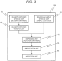
- FIG. 3 is a schematic block diagram showing a second embodiment.
- an inspection device 101 schematically includes a reagent container storage unit 31, a reagent container transfer unit 41, a biological sample storage unit 51, a dispensing unit 61, an amplification unit 71, and an inspection unit 81.
- the reagent container storage unit 31 is a part in which the reagent containers 11 are stored by loading the binding-member-attached reagent container 1 having the above-described configuration in the section of Binding-Member-Attached Reagent Container.
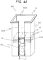
- the reagent container storage unit 31 can include, for example, a storage rack 311 and a reagent container lifting mechanism 312.
- a storage rack 311 and a reagent container lifting mechanism 312.
- the storage rack 311 has, at an upper portion thereof, a loading port 311a through which the binding-member-attached reagent container 1 is loaded, and is a part into which the binding-member-attached reagent container 1 can be loaded such that the plurality of reagent containers 11 are stacked in the vertical direction.
- the storage rack 311 is provided with an opening portion 311b such that the binding member 21 of the loaded binding-member-attached reagent container 1 can be detached from the outside.
- the loading port 311a of the storage rack 311 is formed to have a size corresponding to an outer shape of the reagent container 11 in a plan view. Inside the storage rack 311, an internal space s is provided in which the binding-member-attached reagent container 1 loaded from the loading port 311a can pass vertically downward and a movement of the binding-member-attached reagent container 1 in a horizontal direction can be restricted.
- a shape of the storage rack 311 is not particularly limited as long as the loaded binding-member-attached reagent container 1 can be stored at a predetermined portion while moving along the vertical direction, and the movement of the binding-member-attached reagent container 1 in the horizontal direction can be limited.
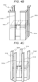
- the storage rack 311 for example, a storage rack (see FIG. 4A ) having a shape in which three side surfaces except for a side surface provided with the opening portion 311b are covered, a storage rack (see FIG. 4B ) having a shape in which substantially L- shaped support columns 311c are erected at four corners in the horizontal direction, a storage rack (see FIG. 4C ) having a shape in which support columns 311d are erected around a periphery in the horizontal direction, or the like can be adopted.
- the storage rack 31 may include a guide member (for example, a rail that guides the binding-member-attached reagent container 1 in the vertical upper-lower direction) that supports the movement of the binding-member-attached reagent container 1, in order to allow the loaded binding-member-attached reagent container 1 to be smoothly and reliably moved.
- a guide member for example, a rail that guides the binding-member-attached reagent container 1 in the vertical upper-lower direction
- the present embodiment includes the storage rack 311 whose three side surfaces are covered, and the opening portion 311b is provided in one side surface (see FIG. 4A ).
- a shape of the opening portion 311b is not particularly limited as long as a detachment operation of the binding member 21 can be performed through the opening portion 311b.
- Examples of the shape of the opening portion 311b include a slit-shaped opening portion (see FIG. 4A ) that has an open upper end and is formed to extend substantially vertically downward from the open upper end.
- the slit-shaped opening portion 311b as shown in FIG. 4A is adopted. According to the slit-shaped opening portion 311b, the binding member 21 can be normally gripped until the reagent containers 11 reach a storage portion in the storage rack 311, and the reagent containers 11 can be reliably stored.
- the opening portion 311b is provided such that a part of the binding member 21 can protrude to the outside of the storage rack 311 through the opening portion 311b.
- the opening portion 311b may be formed such that the gripping portion 211d of the binding member 21 protrudes to the outside of the storage rack 311 through the opening portion 311b, and the user can grip the gripping portion 211d outside the storage rack 311. Accordingly, the binding member 21 can be easily operated, and the binding member 21 can be smoothly removed (detached) from the binding-member-attached reagent container 1.
- the reagent container lifting mechanism 312 is a mechanism that lifts the reagent containers 11 upward when removing the stored reagent containers 11 from the loading port 311a of the storage rack 311.
- a cylinder-type lifter (see FIG. 4A ) provided immediately below the storage rack 311 and capable of pushing the reagent containers 11 upward
- a crane-type lifter (not shown) capable of lifting only the reagent container 11 positioned at an uppermost portion in the storage rack 311 while aspirating the reagent container 11 or the like can be adopted.
- the reagent container storage unit 31 may include a binding member detector (not shown) capable of detecting the presence or absence of the binding member 21 on the stored reagent containers 11 in order to prevent the binding member 21 from being forgotten to be detached from the binding-member-attached reagent container 1 after the binding-member-attached reagent container 1 is loaded to a predetermined position in the internal space of the storage rack 311.
- a binding member detector (not shown) capable of detecting the presence or absence of the binding member 21 on the stored reagent containers 11 in order to prevent the binding member 21 from being forgotten to be detached from the binding-member-attached reagent container 1 after the binding-member-attached reagent container 1 is loaded to a predetermined position in the internal space of the storage rack 311.
- the reagent container transfer unit 41 independently transfers, to the dispensing unit 61, the reagent container 11 which is positioned uppermost among the reagent containers 11 lifted by the reagent container lifting mechanism 312.
- the reagent container transfer unit 41 can be implemented by a transfer unit such as a shuttle-type conveyor (not shown).
- the biological sample storage unit 51 stores a sample container storing a biological sample solution containing nucleic acids to be inspected.
- the dispensing unit 61 takes the reagent 121 in the reagent container 11 transferred by the reagent container transfer unit 41 and the biological sample solution in the sample container stored in the biological sample storage unit 51, and injects the reagent 121 and the biological sample solution into a reaction container.
- the reagent 121 in the reagent container 11 may be taken after the lid body 131 is peeled off, or may be taken after the lid body 131 is penetrated.
- the amplification unit 71 amplifies the nucleic acids contained in the biological sample solution in the reaction container by heating, cooling, or the like using a heater, a Peltier device, or the like.
- the inspection unit 81 inspects the amplified nucleic acids in the reaction container.
- the nucleic acids can be inspected, for example, by analyzing fluorescence emitted from the solution containing the nucleic acids when being irradiated with excitation light.
- the reagent container transfer unit 41, the biological sample storage unit 51, the dispensing unit 61, the amplification unit 71, and the inspection unit 81 may each employ a known technique.
- a method of using the binding-member-attached reagent container 1 in the inspection device 101 will be described.
- a method of using the binding-member-attached reagent container 1 including the binding member 21 including the gripping portion 211d, and loading the binding-member-attached reagent container 1 into the storage rack 311 including the slit-shaped opening portion 311b which has the open upper end and which is formed to extend substantially vertically downward from the open upper end will be described as an example.
- the binding-member-attached reagent container 1 in which the reagent 121 to be inspected is stored is loaded into the reagent container storage unit 31.
- the user loads the binding-member-attached reagent container 1 into the storage rack 311 from the loading port 311a provided in the upper portion of the storage rack 311 while gripping the gripping portion 211d of the binding-member-attached reagent container 1 by pinching the gripping portion 211d with one hand (for example, a thumb and an index finger).
- one hand for example, a thumb and an index finger
- the user lowers the binding-member-attached reagent container 1 to a predetermined position in the storage rack 311 while gripping one end of the gripping portion 211d protruding from the opening portion 311b. At this time, the gripping portion 211d is moved along the opening portion 311b extending substantially vertically downward while being gripped. Accordingly, the plurality of reagent containers 11 (three reagent containers 11 are shown in FIG. 5 as an example) can be integrally operated (moved).
- binding-member-attached reagent container 1 is loaded into the reagent container storage unit 31.
- the user performs similar operations on the above-described binding-member-attached reagent container 1 to load the other binding-member-attached reagent container 1 into the storage rack 311, and disposes the other binding-member-attached reagent container 1 such that a lower end portion of the other binding-member-attached reagent container 1 comes into contact with an upper end portion of the loaded binding-member-attached reagent container 1. Thereafter, the above operations are repeated until a predetermined number of reagent containers 11 are loaded into the storage rack 311.
- the binding member 21 is removed from the binding-member-attached reagent container 1. Specifically, as shown in FIG. 6 , the binding member 21 and the plurality of reagent containers 11 are separated (the binding member 21 is detached) by pulling the binding band 21 toward a user side (separating the binding member 21 from the plurality of reagent containers 11) while gripping the gripping portion 211d.
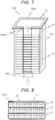
- the reagent containers 11 are in a state of being independent from each other as shown in FIG. 7 , and thus the reagent containers 11 can be individually operated.
- the reagent container 11 is transferred by the reagent container transfer unit 41, only the uppermost positioned reagent container 11 lifted by the reagent container lifting mechanism 312 is transferred to the dispensing unit 61 by a transfer unit.
- the inspection device 101 since the inspection device 101 has the above-described configuration, the plurality of reagent containers 11 can be efficiently stored in the storage rack 311, and the binding member 21 can be easily detached from the binding-member-attached reagent container 1 through the opening portion 311b after the binding-member-attached reagent container 1 is loaded into the storage rack 311. As a result, the reagent containers 11 can be smoothly and efficiently stored in the storage rack 311.
- the inspection device 101 can smoothly and efficiently store the plurality of reagent containers 11. Therefore, the inspection device 101 can be suitably applied to a gene inspection device for handling a large number of reagent containers 11, such as inspecting a biological sample containing nucleic acids.
- the binding-member-attached reagent container 1 in which the binding member 21 includes the gripping portion 211d is described.
- the binding-member-attached reagent container may be a binding-member-attached reagent container including a binding member having no gripping portion protruding outward.
- a reagent container include, for example, as shown in FIG. 8 , a binding-member-attached reagent container 2 including a coupling portion 221a which does not include a protruding gripping portion and in which the plurality of reagent containers 11 are integrally wound and predetermined portions of a binding member 22 are coupled so as to overlap each other.
- the inspection device 101 including the storage rack 311 including the opening portion 311b that has the open upper end and is formed to extend substantially vertically downward from the open upper end is described.
- the opening portion may have any shape as long as the binding member of the stored binding-member-attached reagent container can be detached from the outside.
- Examples of such a storage rack include, for example, as shown in FIG. 9 , an inspection device 102 or the like including a storage rack 321 including opening portions 321b provided at predetermined intervals along the vertical direction so as to correspond to positions where the binding members 21 of the loaded binding-member-attached reagent containers 1 are provided.
- the binding-member-attached reagent container used in the inspection device may be any of those of the present disclosure.
- the binding member 22 may be detached by the user putting his/her hand into the internal space of the storage rack through the opening portion of the storage rack.
- the inspection device 101 is described by using the gene inspection device as an example.
- the inspection device according to the invention can be applied to any other inspection device as long as effects of the invention are not impaired.
Landscapes
- Health & Medical Sciences (AREA)
- Chemical & Material Sciences (AREA)
- Clinical Laboratory Science (AREA)
- Chemical Kinetics & Catalysis (AREA)
- Medicinal Chemistry (AREA)
- Life Sciences & Earth Sciences (AREA)
- Physics & Mathematics (AREA)
- Analytical Chemistry (AREA)
- Biochemistry (AREA)
- General Health & Medical Sciences (AREA)
- General Physics & Mathematics (AREA)
- Immunology (AREA)
- Pathology (AREA)
- Automatic Analysis And Handling Materials Therefor (AREA)
Abstract
Description
- The present invention relates to a binding-member-attached reagent container and an inspection device.
- As a device for inspecting a biological sample, for example, a device for analyzing the biological sample using a reagent is known.
- In such an inspection device, for example, a plurality of reagent containers are collectively stored in advance, in order to allow a large number of inspections to be efficiently performed.
- As the device capable of storing a plurality of reagent containers as described above, for example, a biological sample analysis instrument is proposed which includes a plate loading assembly capable of storing a large number of reagent containers by individually placing each of a plurality of plate-shaped reagent containers on a nest of a plate rack (for example, see PTL 1).
- PTL 1:
JP2017-523809A - However, in the related-art biological sample analysis instrument as described above, since the plates are set on the nest of the plate rack while being gripped one by one, it takes time and effort to set the plates, and there is also a risk that the reagents are contaminated when a user operates the plates.
- The invention has been made in view of the above circumstances, and an object of the invention is to provide a binding-member-attached reagent container allowing a plurality of reagent containers to be integrally operated and capable of preventing a reagent from being contaminated without directly touching the reagent containers, and an inspection device using the binding-member-attached reagent container.
- According to one aspect of the present disclosure, a binding-member-attached reagent container includes a plurality of reagent containers provided in series and in contact with each other, and a detachable strip-shaped binding member integrally surrounding the plurality of reagent containers.
- According to another aspect of the present disclosure, an inspection device allowing the binding-member-attached reagent container to be loaded therein includes a storage rack having, at an upper portion thereof, a loading port through which the binding-member-attached reagent container is loaded, and configured to allow the binding-member-attached reagent container to be loaded such that the plurality of reagent containers are stacked in a vertical direction. The storage rack is provided with an opening portion such that the binding member of the loaded binding-member-attached reagent container is detachable from an outside.
- The invention can provide a binding-member-attached reagent container allowing a plurality of reagent containers to be integrally operated and preventing a reagent from being contaminated without directly touching the reagent containers, and an inspection device using the binding-member-attached reagent container.
-
-
FIG. 1 is a schematic side view showing a first embodiment. -
FIG. 2 is a schematic perspective view showing a reagent container inFIG. 1 , and shows a state in which a part of a lid body is cut out. -
FIG. 3 is a schematic block diagram showing a second embodiment. -
FIG. 4A is a schematic perspective view showing a reagent container storage unit inFIG. 3 . -
FIG. 4B is a schematic perspective view showing the reagent container storage unit inFIG. 3 . -
FIG. 4C is a schematic perspective view showing the reagent container storage unit inFIG. 3 . -
FIG. 5 is a schematic perspective view showing a usage state according to the second embodiment, and shows a state in which a binding-member-attached reagent container is being loaded into a storage rack. -
FIG. 6 is a schematic perspective view showing the usage state according to the second embodiment, and shows a state in which a binding member is being removed. -
FIG. 7 is a schematic perspective view showing the usage state according to the second embodiment, and shows a state in which the binding member is removed. -
FIG. 8 is a schematic side view showing a modification of the first embodiment. -
FIG. 9 is a schematic perspective view showing a modification of the second embodiment, and shows the reagent container storage unit. - In the present description, a reagent container used for inspecting a biological sample will be described as an example of a binding-member-attached reagent container, and a gene inspection device used for a gene inspection will be described as an example of an inspection device.
- For example, the gene inspection device performs an inspection of a gene by amplifying a trace amount of nucleic acids such as deoxyribonucleic acid (DNA) or ribonucleic acid (RNA) contained in a biological sample using a reagent, then irradiating a solution containing the amplified nucleic acid (hereinafter, also referred to as "nucleic-acid-containing solution") with excitation light, and thus analyzing fluorescence emitted from the solution.
- The gene inspection device can include, for example, a reagent container storage unit which stores a reagent container, a biological sample storage unit which stores a biological sample, a dispensing unit which dispenses a reagent in the reagent container and the biological sample in the biological sample storage unit to generate the nucleic-acid-containing solution, an amplification unit which amplifies the generated nucleic-acid-containing solution, and an inspection unit which inspects the amplified nucleic-acid-containing solution.
- The binding-member-attached reagent container according to the present disclosure can be used, for example, as the reagent container stored in the reagent container storage unit described above. The inspection device according to the present disclosure can be used as, for example, the gene inspection device described above.
- Hereinafter, embodiments of the binding-member-attached reagent container and the inspection device will be described with reference to the drawings, but the invention is not limited to the embodiments described in the drawings.
- The binding-member-attached reagent container according to the present disclosure includes a plurality of reagent containers provided in series and in contact with each other, and a detachable strip-shaped binding member integrally surrounding the plurality of reagent containers. Hereinafter, the binding-member-attached reagent container will be described in detail.
-
FIG. 1 is a schematic side view showing a first embodiment. As shown inFIG. 1 , a binding-member-attachedreagent container 1 schematically includes a plurality ofreagent containers 11 and abinding member 21. - The plurality of
reagent containers 11 are provided in series and in contact with each other. As shown inFIGS. 1 and 2 , each of thereagent containers 11 can include, for example, acontainer body 111, areagent 121, and alid body 131. - The
container body 111 stores thereagent 121. Specifically, thecontainer body 111 has, for example, a well 111a for storing a single taking amount of thereagent 121. Thewell 111a is formed of a recessed container having an opening at an upper portion thereof. - A large number of
wells 111a are usually provided in thecontainer body 111, in order to allow many biological samples to be efficiently inspected. An arrangement of thewells 111a in thecontainer body 111 is not particularly limited. The large number ofwells 111a may be provided in, for example, a matrix shape. - The
reagent 121 is stored in each of thewells 111a. Thereagent 121 to be stored is not particularly limited. Examples of thereagent 121 include a reagent for amplifying a gene, a reagent necessary for nucleic acid extraction, and a reagent containing magnetic particles. - The
lid body 131 is a member that covers the openings of thewells 111a. Thelid body 131 is made of, for example, a material having a light shielding property and an oxygen impermeable property. Thelid body 131 can be formed of, for example, a film-shaped member. Thelid body 131 is fixed to thecontainer body 111 in a state in which thelid body 131 can be peeled off or penetrated. When dispensing the reagent, thelid body 131 is peeled off from thecontainer body 111 or penetrated, and accordingly, thereagent 121 is removed from thewell 111a. Examples of the material for forming thelid body 131 include a metal material such as aluminum, and a multilayer composite material obtained by bonding thin layers of aluminum and polypropylene or the like. - The
binding member 21 is a detachable strip-shaped member integrally surrounding the plurality ofreagent containers 11. Specifically, for example, thebinding member 21 can be formed of an elongated band having two end portions (hereinafter, also referred to as a "binding band 21") . - The
binding band 21 binds the plurality ofreagent containers 11 by, for example, integrally winding thereagent containers 11 along a peripheral direction (see animaginary line 21 inFIG. 2 ) in which thereagent containers 11 are stacked. The bindingband 21 is provided with acoupling portion 211a at an appropriate position such that thereagent containers 11 are not separated from each other. The strip-shaped member constituting the bindingband 21 is coupled at thecoupling portion 211a to annularly surround the plurality ofreagent containers 11 and integrally fix thereagent containers 11. - Examples of a coupling mode of the
coupling portion 211a include coupling using an adhesive or a pressure-sensitive adhesive, coupling in which the bindingband 21 is overlapped and welded (heat-sealed), and coupling using a hook-and-loop fastener. Among the coupling modes, the coupling implemented by welding (heat-sealing) which does not require other materials is preferable. Accordingly, thereagent 121 can be further prevented from being contaminated. - The binding
member 21 according to the present embodiment includes agripping portion 211d that protrudes outward and is capable of being gripped. Specifically, for example, the grippingportion 211d may be provided by extending the end portion of the bindingband 21 outward from thecoupling portion 211a so as to be away from thereagent containers 11. - Since the binding
member 21 according to the present embodiment includes the grippingportion 211d, for example, the bindingmember 21 can be removed (detached) from the plurality ofreagent containers 11 by pulling one end of the bindingmember 21 in the protrudinggripping portion 211d. Even in a state in which a plurality of binding-member-attachedreagent containers 1 are stacked on each other, since the grippingportion 211d protrudes outward, the desired bindingmember 21 can be easily removed by pulling the protrudinggripping portion 211d (seeFIG. 6 ). - The binding
member 21 may be provided with a label such as a bar code, in order to allow a type, a manufacturing lot number, and the like of the reagent to be grasped. - A material constituting the binding
member 21 is not particularly limited as long as the bindingmember 21 can integrally surround the plurality ofreagent containers 11. Examples of the above material include a resin material such as polyethylene terephthalate (PET). By using the above material, thereagent containers 11 can be easily bound (for example, welded by heat-sealing), and the desired detachable coupling portion can be reliably formed. - The binding-member-attached
reagent container 1 is operated by, for example, a user gripping thegripping portion 211d of the bindingmember 21. In the binding-member-attachedreagent container 1, the plurality ofreagent containers 11 are integrally bound. Therefore, the user can handle the reagent containers 11 (for example, transport the reagent containers 11) without directly touching thereagent containers 11 by gripping only the grippingportion 211d. - The binding
member 21 is formed to be detachable. Therefore, when thereagent containers 11 are to be used, the bindingmember 21 can be removed from the binding-member-attachedreagent container 1 by releasing the coupling of the bindingmember 21 at thecoupling portion 211a. A specific example in which the binding-member-attachedreagent container 1 is applied to the inspection device will be described in detail in a section of Inspection Device. - As described above, since the binding-member-attached
reagent container 1 has the above-described configuration, the plurality ofreagent containers 11 can be integrally operated and thereagent 121 can be prevented from being contaminated without directly touching thereagent containers 11. - The inspection device according to the present disclosure is an inspection device allowing the above binding-member-attached reagent container to be loaded therein, and includes a storage rack having, at an upper portion thereof, a loading port through which the above binding-member-attached reagent container is loaded, and configured to allow the above binding-member-attached reagent container to be loaded such that the plurality of reagent containers described above are stacked in a vertical direction. The storage rack is provided with an opening portion such that the binding member of the loaded binding-member-attached reagent container is detachable from an outside. Hereinafter, the inspection device will be described in detail by using the gene inspection device as an example.
-
FIG. 3 is a schematic block diagram showing a second embodiment. As shown inFIG. 3 , aninspection device 101 schematically includes a reagentcontainer storage unit 31, a reagentcontainer transfer unit 41, a biologicalsample storage unit 51, a dispensingunit 61, anamplification unit 71, and aninspection unit 81. - The reagent
container storage unit 31 is a part in which thereagent containers 11 are stored by loading the binding-member-attachedreagent container 1 having the above-described configuration in the section of Binding-Member-Attached Reagent Container. Specifically, as shown inFIG. 4A , the reagentcontainer storage unit 31 can include, for example, astorage rack 311 and a reagentcontainer lifting mechanism 312. Here, an example using the binding-member-attachedreagent container 1 including the grippingportion 211d as shown inFIG. 1 will be described. - The
storage rack 311 has, at an upper portion thereof, aloading port 311a through which the binding-member-attachedreagent container 1 is loaded, and is a part into which the binding-member-attachedreagent container 1 can be loaded such that the plurality ofreagent containers 11 are stacked in the vertical direction. Thestorage rack 311 is provided with anopening portion 311b such that the bindingmember 21 of the loaded binding-member-attachedreagent container 1 can be detached from the outside. - The
loading port 311a of thestorage rack 311 is formed to have a size corresponding to an outer shape of thereagent container 11 in a plan view. Inside thestorage rack 311, an internal space s is provided in which the binding-member-attachedreagent container 1 loaded from theloading port 311a can pass vertically downward and a movement of the binding-member-attachedreagent container 1 in a horizontal direction can be restricted. - A shape of the
storage rack 311 is not particularly limited as long as the loaded binding-member-attachedreagent container 1 can be stored at a predetermined portion while moving along the vertical direction, and the movement of the binding-member-attachedreagent container 1 in the horizontal direction can be limited. As thestorage rack 311, for example, a storage rack (seeFIG. 4A ) having a shape in which three side surfaces except for a side surface provided with theopening portion 311b are covered, a storage rack (seeFIG. 4B ) having a shape in which substantially L-shapedsupport columns 311c are erected at four corners in the horizontal direction, a storage rack (seeFIG. 4C ) having a shape in which supportcolumns 311d are erected around a periphery in the horizontal direction, or the like can be adopted. - The
storage rack 31 may include a guide member (for example, a rail that guides the binding-member-attachedreagent container 1 in the vertical upper-lower direction) that supports the movement of the binding-member-attachedreagent container 1, in order to allow the loaded binding-member-attachedreagent container 1 to be smoothly and reliably moved. - The present embodiment includes the
storage rack 311 whose three side surfaces are covered, and theopening portion 311b is provided in one side surface (seeFIG. 4A ). - A shape of the
opening portion 311b is not particularly limited as long as a detachment operation of the bindingmember 21 can be performed through theopening portion 311b. Examples of the shape of theopening portion 311b include a slit-shaped opening portion (seeFIG. 4A ) that has an open upper end and is formed to extend substantially vertically downward from the open upper end. - In the present embodiment, the slit-shaped
opening portion 311b as shown inFIG. 4A is adopted. According to the slit-shapedopening portion 311b, the bindingmember 21 can be normally gripped until thereagent containers 11 reach a storage portion in thestorage rack 311, and thereagent containers 11 can be reliably stored. - In the present embodiment, the
opening portion 311b is provided such that a part of the bindingmember 21 can protrude to the outside of thestorage rack 311 through theopening portion 311b. Specifically, for example, theopening portion 311b may be formed such that the grippingportion 211d of the bindingmember 21 protrudes to the outside of thestorage rack 311 through theopening portion 311b, and the user can grip the grippingportion 211d outside thestorage rack 311. Accordingly, the bindingmember 21 can be easily operated, and the bindingmember 21 can be smoothly removed (detached) from the binding-member-attachedreagent container 1. - The reagent
container lifting mechanism 312 is a mechanism that lifts thereagent containers 11 upward when removing the storedreagent containers 11 from theloading port 311a of thestorage rack 311. As the reagentcontainer lifting mechanism 312, for example, a cylinder-type lifter (seeFIG. 4A ) provided immediately below thestorage rack 311 and capable of pushing thereagent containers 11 upward, a crane-type lifter (not shown) capable of lifting only thereagent container 11 positioned at an uppermost portion in thestorage rack 311 while aspirating thereagent container 11 or the like can be adopted. - The reagent
container storage unit 31 may include a binding member detector (not shown) capable of detecting the presence or absence of the bindingmember 21 on the storedreagent containers 11 in order to prevent the bindingmember 21 from being forgotten to be detached from the binding-member-attachedreagent container 1 after the binding-member-attachedreagent container 1 is loaded to a predetermined position in the internal space of thestorage rack 311. - The reagent
container transfer unit 41 independently transfers, to the dispensingunit 61, thereagent container 11 which is positioned uppermost among thereagent containers 11 lifted by the reagentcontainer lifting mechanism 312. The reagentcontainer transfer unit 41 can be implemented by a transfer unit such as a shuttle-type conveyor (not shown). - The biological
sample storage unit 51 stores a sample container storing a biological sample solution containing nucleic acids to be inspected. The dispensingunit 61 takes thereagent 121 in thereagent container 11 transferred by the reagentcontainer transfer unit 41 and the biological sample solution in the sample container stored in the biologicalsample storage unit 51, and injects thereagent 121 and the biological sample solution into a reaction container. Thereagent 121 in thereagent container 11 may be taken after thelid body 131 is peeled off, or may be taken after thelid body 131 is penetrated. Theamplification unit 71 amplifies the nucleic acids contained in the biological sample solution in the reaction container by heating, cooling, or the like using a heater, a Peltier device, or the like. Theinspection unit 81 inspects the amplified nucleic acids in the reaction container. The nucleic acids can be inspected, for example, by analyzing fluorescence emitted from the solution containing the nucleic acids when being irradiated with excitation light. - The reagent
container transfer unit 41, the biologicalsample storage unit 51, the dispensingunit 61, theamplification unit 71, and theinspection unit 81 may each employ a known technique. - Next, a method of using the binding-member-attached
reagent container 1 in theinspection device 101 will be described. Here, a method of using the binding-member-attachedreagent container 1 including the bindingmember 21 including the grippingportion 211d, and loading the binding-member-attachedreagent container 1 into thestorage rack 311 including the slit-shapedopening portion 311b which has the open upper end and which is formed to extend substantially vertically downward from the open upper end will be described as an example. - First, the binding-member-attached
reagent container 1 in which thereagent 121 to be inspected is stored is loaded into the reagentcontainer storage unit 31. Specifically, for example, the user loads the binding-member-attachedreagent container 1 into thestorage rack 311 from theloading port 311a provided in the upper portion of thestorage rack 311 while gripping thegripping portion 211d of the binding-member-attachedreagent container 1 by pinching the grippingportion 211d with one hand (for example, a thumb and an index finger). Next, as shown inFIG. 5 , the user lowers the binding-member-attachedreagent container 1 to a predetermined position in thestorage rack 311 while gripping one end of the grippingportion 211d protruding from theopening portion 311b. At this time, the grippingportion 211d is moved along theopening portion 311b extending substantially vertically downward while being gripped. Accordingly, the plurality of reagent containers 11 (threereagent containers 11 are shown inFIG. 5 as an example) can be integrally operated (moved). - Next, another binding-member-attached
reagent container 1 is loaded into the reagentcontainer storage unit 31. The user performs similar operations on the above-described binding-member-attachedreagent container 1 to load the other binding-member-attachedreagent container 1 into thestorage rack 311, and disposes the other binding-member-attachedreagent container 1 such that a lower end portion of the other binding-member-attachedreagent container 1 comes into contact with an upper end portion of the loaded binding-member-attachedreagent container 1. Thereafter, the above operations are repeated until a predetermined number ofreagent containers 11 are loaded into thestorage rack 311. - Next, the binding
member 21 is removed from the binding-member-attachedreagent container 1. Specifically, as shown inFIG. 6 , the bindingmember 21 and the plurality ofreagent containers 11 are separated (the bindingmember 21 is detached) by pulling the bindingband 21 toward a user side (separating the bindingmember 21 from the plurality of reagent containers 11) while gripping thegripping portion 211d. By sequentially repeating this operation on each binding-member-attachedreagent container 1, thereagent containers 11 are in a state of being independent from each other as shown inFIG. 7 , and thus thereagent containers 11 can be individually operated. When thereagent container 11 is transferred by the reagentcontainer transfer unit 41, only the uppermost positionedreagent container 11 lifted by the reagentcontainer lifting mechanism 312 is transferred to the dispensingunit 61 by a transfer unit. - As described above, since the
inspection device 101 has the above-described configuration, the plurality ofreagent containers 11 can be efficiently stored in thestorage rack 311, and the bindingmember 21 can be easily detached from the binding-member-attachedreagent container 1 through theopening portion 311b after the binding-member-attachedreagent container 1 is loaded into thestorage rack 311. As a result, thereagent containers 11 can be smoothly and efficiently stored in thestorage rack 311. - In this manner, the
inspection device 101 can smoothly and efficiently store the plurality ofreagent containers 11. Therefore, theinspection device 101 can be suitably applied to a gene inspection device for handling a large number ofreagent containers 11, such as inspecting a biological sample containing nucleic acids. - The present disclosure is not limited to the configurations of the above-described embodiments, is indicated by the claims, and is intended to include all changes within the meaning and scope equivalent to the claims. A part of the configuration of the above-described embodiment may be deleted or replaced with another configuration, and another configuration may be added to the configuration of the above-described embodiment.
- For example, in the first embodiment described above, the binding-member-attached
reagent container 1 in which the bindingmember 21 includes the grippingportion 211d is described. However, the binding-member-attached reagent container may be a binding-member-attached reagent container including a binding member having no gripping portion protruding outward. Examples of such a reagent container include, for example, as shown inFIG. 8 , a binding-member-attachedreagent container 2 including acoupling portion 221a which does not include a protruding gripping portion and in which the plurality ofreagent containers 11 are integrally wound and predetermined portions of a bindingmember 22 are coupled so as to overlap each other. - Further, in the second embodiment described above, the
inspection device 101 including thestorage rack 311 including theopening portion 311b that has the open upper end and is formed to extend substantially vertically downward from the open upper end is described. However, the opening portion may have any shape as long as the binding member of the stored binding-member-attached reagent container can be detached from the outside. Examples of such a storage rack include, for example, as shown inFIG. 9 , aninspection device 102 or the like including astorage rack 321 including openingportions 321b provided at predetermined intervals along the vertical direction so as to correspond to positions where the bindingmembers 21 of the loaded binding-member-attachedreagent containers 1 are provided. - In the second embodiment described above, the example of the
inspection device 101 using the binding-member-attachedreagent container 1 including the grippingportion 211d is described. However, the binding-member-attached reagent container used in the inspection device may be any of those of the present disclosure. For example, when the binding-member-attachedreagent container 2 as shown inFIG. 8 is used, the bindingmember 22 may be detached by the user putting his/her hand into the internal space of the storage rack through the opening portion of the storage rack. - In the second embodiment described above, the
inspection device 101 is described by using the gene inspection device as an example. However, the inspection device according to the invention can be applied to any other inspection device as long as effects of the invention are not impaired.
Claims (5)
- A binding-member-attached reagent container, comprising:a plurality of reagent containers provided in series and in contact with each other; anda detachable strip-shaped binding member integrally surrounding the plurality of reagent containers.
- The binding-member-attached reagent container according to claim 1, wherein
the binding member includes a gripping portion that protrudes outward and is capable of being gripped. - An inspection device allowing the binding-member-attached reagent container according to claim 1 or 2 to be loaded therein, the inspection device comprising:a storage rack having, at an upper portion thereof, a loading port through which the binding-member-attached reagent container is loaded, and configured to allow the binding-member-attached reagent container to be loaded such that the plurality of reagent containers are stacked in a vertical direction, whereinthe storage rack is provided with an opening portion such that the binding member of the loaded binding-member-attached reagent container is detachable from an outside.
- The inspection device according to claim 3, wherein
the opening portion includes an open upper end and is formed to extend substantially vertically downward from the open upper end. - The inspection device according to claim 3, wherein
the opening portion is provided such that a part of the binding member is capable of protruding to an outside of the storage rack through the opening portion.
Applications Claiming Priority (1)
| Application Number | Priority Date | Filing Date | Title |
|---|---|---|---|
| PCT/JP2022/023992 WO2023243006A1 (en) | 2022-06-15 | 2022-06-15 | Bundling member-equipped reagent container and testing device |
Publications (2)
| Publication Number | Publication Date |
|---|---|
| EP4541878A1 true EP4541878A1 (en) | 2025-04-23 |
| EP4541878A4 EP4541878A4 (en) | 2026-04-01 |
Family
ID=89192453
Family Applications (1)
| Application Number | Title | Priority Date | Filing Date |
|---|---|---|---|
| EP22946825.1A Pending EP4541878A4 (en) | 2022-06-15 | 2022-06-15 | Reagent container and test device equipped with a bundling element |
Country Status (6)
| Country | Link |
|---|---|
| US (1) | US20250367669A1 (en) |
| EP (1) | EP4541878A4 (en) |
| JP (1) | JP7894452B2 (en) |
| KR (1) | KR20250004363A (en) |
| CN (1) | CN119317702A (en) |
| WO (1) | WO2023243006A1 (en) |
Family Cites Families (4)
| Publication number | Priority date | Publication date | Assignee | Title |
|---|---|---|---|---|
| US6193102B1 (en) * | 1999-04-30 | 2001-02-27 | Incyte Pharmaceuticals, Inc. | Plate stacker apparatus |
| US20050078307A1 (en) * | 2003-10-14 | 2005-04-14 | Davis Freeman | Packaging of multiple fluid receptacles |
| US7998708B2 (en) * | 2006-03-24 | 2011-08-16 | Handylab, Inc. | Microfluidic system for amplifying and detecting polynucleotides in parallel |
| DK3709026T3 (en) * | 2014-07-28 | 2024-09-23 | Lgc Genomics Llc | Instrument for analyzing biological samples and reagents |
-
2022
- 2022-06-15 WO PCT/JP2022/023992 patent/WO2023243006A1/en not_active Ceased
- 2022-06-15 EP EP22946825.1A patent/EP4541878A4/en active Pending
- 2022-06-15 JP JP2024527998A patent/JP7894452B2/en active Active
- 2022-06-15 KR KR1020247040125A patent/KR20250004363A/en active Pending
- 2022-06-15 US US18/874,340 patent/US20250367669A1/en active Pending
- 2022-06-15 CN CN202280096788.3A patent/CN119317702A/en active Pending
Also Published As
| Publication number | Publication date |
|---|---|
| JP7894452B2 (en) | 2026-07-23 |
| KR20250004363A (en) | 2025-01-07 |
| US20250367669A1 (en) | 2025-12-04 |
| JPWO2023243006A1 (en) | 2023-12-21 |
| WO2023243006A1 (en) | 2023-12-21 |
| EP4541878A4 (en) | 2026-04-01 |
| CN119317702A (en) | 2025-01-14 |
Similar Documents
| Publication | Publication Date | Title |
|---|---|---|
| AU2022202311B2 (en) | Automated diagnostic analyzer and method for its operation | |
| JP6316473B2 (en) | Unitized reagent strip | |
| CN104138772B (en) | The device for feeding caps of biological sample container containing and the method for container capping | |
| CN109313207B (en) | Sample processing and measuring system | |
| EP2538227B1 (en) | Device for decapping and recapping sample tubes | |
| JP6619080B2 (en) | Automatic analyzer | |
| CN105785059B (en) | Reagent container | |
| JP5872786B2 (en) | Cassette with multiwell plate | |
| EP2515120B1 (en) | Supply unit for continuous loading | |
| EP3814778B1 (en) | Automatic analyzer | |
| JP7682207B2 (en) | Gripper device with reduced contamination risk | |
| US20250367669A1 (en) | Binding-member-attached reagent container, and inspection device | |
| JP4246720B2 (en) | Equipment with lift system | |
| CN110494754B (en) | Object processing and measurement system | |
| US12313643B2 (en) | Reagent drawer and associated detector mounted to a slider capable of extending from an automatic analyzer housing | |
| JP5991003B2 (en) | Container supply device and automatic analyzer equipped with the same | |
| RU2824196C1 (en) | Device for preparing object to be tested and combined nucleic acid testing machine with device for preparing object to be tested • | |
| CN120718747A (en) | Sample analyzer |
Legal Events
| Date | Code | Title | Description |
|---|---|---|---|
| STAA | Information on the status of an ep patent application or granted ep patent |
Free format text: STATUS: THE INTERNATIONAL PUBLICATION HAS BEEN MADE |
|
| PUAI | Public reference made under article 153(3) epc to a published international application that has entered the european phase |
Free format text: ORIGINAL CODE: 0009012 |
|
| STAA | Information on the status of an ep patent application or granted ep patent |
Free format text: STATUS: REQUEST FOR EXAMINATION WAS MADE |
|
| 17P | Request for examination filed |
Effective date: 20250115 |
|
| AK | Designated contracting states |
Kind code of ref document: A1 Designated state(s): AL AT BE BG CH CY CZ DE DK EE ES FI FR GB GR HR HU IE IS IT LI LT LU LV MC MK MT NL NO PL PT RO RS SE SI SK SM TR |
|
| DAV | Request for validation of the european patent (deleted) | ||
| DAX | Request for extension of the european patent (deleted) | ||
| REG | Reference to a national code |
Ref country code: DE Ref legal event code: R079 Free format text: PREVIOUS MAIN CLASS: C12M0001000000 Ipc: B65B0027000000 |
|
| A4 | Supplementary search report drawn up and despatched |
Effective date: 20260304 |
|
| RIC1 | Information provided on ipc code assigned before grant |
Ipc: B65B 27/00 20060101AFI20260226BHEP Ipc: G01N 35/00 20060101ALI20260226BHEP Ipc: B01L 3/00 20060101ALI20260226BHEP |