EP4541758A1 - Package holding assembly - Google Patents
Package holding assembly Download PDFInfo
- Publication number
- EP4541758A1 EP4541758A1 EP24207641.2A EP24207641A EP4541758A1 EP 4541758 A1 EP4541758 A1 EP 4541758A1 EP 24207641 A EP24207641 A EP 24207641A EP 4541758 A1 EP4541758 A1 EP 4541758A1
- Authority
- EP
- European Patent Office
- Prior art keywords
- package
- unit
- holding
- holding unit
- movable cover
- Prior art date
- Legal status (The legal status is an assumption and is not a legal conclusion. Google has not performed a legal analysis and makes no representation as to the accuracy of the status listed.)
- Pending
Links
Images


Classifications
-
- B—PERFORMING OPERATIONS; TRANSPORTING
- B67—OPENING, CLOSING OR CLEANING BOTTLES, JARS OR SIMILAR CONTAINERS; LIQUID HANDLING
- B67B—APPLYING CLOSURE MEMBERS TO BOTTLES JARS, OR SIMILAR CONTAINERS; OPENING CLOSED CONTAINERS
- B67B3/00—Closing bottles, jars or similar containers by applying caps
- B67B3/20—Closing bottles, jars or similar containers by applying caps by applying and rotating preformed threaded caps
- B67B3/206—Means for preventing rotation of the container or cap
-
- B—PERFORMING OPERATIONS; TRANSPORTING
- B65—CONVEYING; PACKING; STORING; HANDLING THIN OR FILAMENTARY MATERIAL
- B65B—MACHINES, APPARATUS OR DEVICES FOR, OR METHODS OF, PACKAGING ARTICLES OR MATERIALS; UNPACKING
- B65B7/00—Closing containers or receptacles after filling
- B65B7/16—Closing semi-rigid or rigid containers or receptacles not deformed by, or not taking-up shape of, contents, e.g. boxes or cartons
- B65B7/28—Closing semi-rigid or rigid containers or receptacles not deformed by, or not taking-up shape of, contents, e.g. boxes or cartons by applying separate preformed closures, e.g. lids, covers
- B65B7/2828—Closing semi-rigid or rigid containers or receptacles not deformed by, or not taking-up shape of, contents, e.g. boxes or cartons by applying separate preformed closures, e.g. lids, covers inserting and rotating screw stoppers
Definitions
- the invention relates to a package holding assembly, a capping station for a filing machine, and a method of applying a cap on a neck of a package.
- Packaging machines are industrial devices designed to efficiently and consistently package products into various types of containers or packaging materials. These machines play a critical role in the manufacturing and distribution of products across a wide range of industries. Examples of such products are beverage and dairy products.
- a packaging machine may comprise different units such as a package forming unit, a package sterilisation unit and a package filing unit.
- the packaging machines have developed significantly during the past years e.g. in terms of automation, hygiene and safety. However, the interplay of tolerances within the packaging machine may result in significant variations which may vary from one machine to another machine. Thus, there is a need to further improve the packaging machines in terms of consistency and accuracy.
- the capping station comprises a package holding unit configured to hold a package while a cap is being applied on a neck of the package.
- package holding units typically comprise several parts.
- An example of drawbacks of such package holding units is that the parts of the holding unit need to be carefully attached to one another and also to other parts of the capping station to hold the package in place, as a tolerance chain of the parts of the holding unit may lead to significant variations. Such variations may vary from one machine to another machine. Such variations may e.g. result in that the holding unit may not hold the packaging at a fixed position while a cap is being applied on the neck of the package.
- Another example of drawbacks of such package holding units is that the position of the parts of the holding unit need to be calibrated regularly.
- the package holding assembly comprises a base unit.
- the base unit is arranged along a longitudinal direction and extends from a first end of the base unit to a second end of the base unit along the longitudinal direction.
- the package holding assembly further comprises a movable cover unit.
- the movable cover unit is arranged along the longitudinal direction and extends from a first end of the movable cover unit to a second end of the movable cover unit along the longitudinal direction.
- the package holding assembly further comprises a holding unit.
- the holding unit is arranged along a transverse direction at the second end of the base unit.
- the holding unit comprises an opening.
- the movable cover unit is configured to pivotably rotate in a first direction around the longitudinal direction to cover the base unit to form a closed state.
- the movable cover unit In the closed state, the movable cover unit is configured to cover the base unit.
- the movable cover unit and the base unit are configured to form a cavity to receive and support a package.
- a portion of the base unit and the first end of the movable cover unit are configured to form an inlet for the cavity.
- the package holding assembly In the closed state, the package holding assembly is configured to receive a main body of the package via the inlet of the cavity.
- the main body of the package is moved inside the cavity along the longitudinal direction towards the opening of the holding unit.
- the holding unit is configured to receive a portion of the main body of the package via the opening, and to fixedly hold a periphery of the portion of the main body of the package.
- the holding unit is advantageous in that it allows for fixedly holding/maintaining/supporting the portion of the main body of the package while maintaining/preserving a shape and position of the portion of the main body of the package.
- the holding unit prevents, or at least mitigates, movement of the main body of the package. Examples of the movement of the main body of the package are movements along the longitudinal direction, opposite to the longitudinal direction, along the transverse direction and/or opposite to the transverse direction.
- the holding unit prevents, or at least mitigates, rotation of the main body of the package. Examples of the rotation of the main body of the package are rotation along the first direction and/or along the second direction.
- the holding unit is further advantageous in that it allows for fixedly holding/maintaining/supporting the portion of the main body of the package while a cap is being applied on a neck of the package.
- the holding unit allows for fixedly holding the periphery of the portion of the main body of the package in an accurate, reliable and consistent manner e.g. when a cap is being applied on the package.
- the package may comprise a main body, a neck and a shoulder.
- the main body of the package may correspond to where the product e.g. a dairy product is held.
- the neck may correspond to an upper part of the package.
- the neck may be configured to receive a cap/lid.
- the shoulder may connect the main body to the neck.
- the portion of the main body of the package may be a portion/part of the package where the shoulder of the package meets the main body.
- the package may comprise an upper end and a lower end. An upper end of the package may correspond to the end of the package comprising the neck.
- the lower end of the package may correspond to the other end of the package not comprising the neck.
- the holding assembly may receive the package from the upper end of the package comprising the neck.
- the base unit is arranged along the longitudinal direction and extends from the first end of the base unit to the second end of the base unit along the longitudinal direction.
- the first end and the second end of the base unit may be arranged opposite to each other along the longitudinal direction.
- the first end of the base unit may be arranged at a first position along the longitudinal direction.
- the second end of the base unit may be arranged at a second position along the longitudinal direction.
- the second position may correspond to a position of the holding unit, along the longitudinal direction.
- the movable cover unit is arranged along the longitudinal direction and extends from the first end of the movable cover unit to the second end of the movable cover unit along the longitudinal direction.
- the first end of the movable cover unit may be arranged at a third position.
- the third position may correspond to a position of the inlet of the cavity of the package holding assembly in the closed state.
- the second end of the movable cover unit may be arranged at the second position along the longitudinal direction.
- the second position may correspond to the position of the holding unit, along the longitudinal direction.
- the holding unit may be a guide or a holding ring suitable for fixedly holding the periphery of the portion of the main body of the package.
- the holding unit may comprise two sides. A first side of the holding unit may face the cavity. A second side of the holding unit may not face the cavity. In the closed state and when the holding unit fixedly holds the periphery of the portion of the main body of the package, the main body of the package may be arranged on the first side and the neck of the package may be arranged on the second side of the holding unit.
- the portion of the base unit and the first end of the movable cover unit are configured to form the inlet for the cavity.
- the main body of the package may enter the cavity via the inlet from the upper end of the package comprising the neck.
- the main body of the package may leave the cavity via the opening of the holding unit.
- the opening of the holding unit may form an outlet for the cavity.
- longitudinal direction is hereby meant a direction parallel to the direction of movement of the main body of the package inside the cavity of the packaging holding assembly in the closed state.
- transverse direction is hereby meant a direction opposite/perpendicular to the longitudinal direction.
- Two package holding assemblies may be arranged side by side. Thereby, they may allow for providing double capacity. In addition, they may allow for performing maintenance on one package holding assembly without stopping a production line on the other package holding assembly.
- the holding unit consists of one piece. Thereby, it may allow for an even more precise and accurate positioning of the holding unit inside the package holding assembly, as installation/positioning/calibration of the holding unit may not require attaching parts of the holding unit together. This in turn may allow for preventing or at least mitigating variations due to interplay of tolerances of different parts of the holding unit.
- the one-piece holding unit may allow for fixedly holding the periphery of the portion of the main body of the package in an accurate, reliable and consistent manner.
- the one-piece holding unit may allow for, or at least facilitate, providing consistent and uniform packaging holding assemblies having no variations, or at least reduced variations, with respect to one another.
- the one-piece holding unit may also allow for producing/manufacturing the holding unit in a simple, user-friendly and cost-effective manner.
- the opening of the holding unit has a rounded rectangular shape.
- the rounded rectangular shape of the opening of the holding unit may correspond to a shape of the main body of the package.
- the inner rounded corners of the rectangular shape may avoid/prevent, or at least mitigate, damaging the main body of the package. This may in turn provide an improved package holding assembly in terms of reliability while maintaining hygiene.
- the rounded rectangular shape is hereby meant a rectangular shape with inner rounded corners.
- the opening of the holding unit comprises a chamfered edge that faces the cavity.
- the chamfered edge of the opening of the holding unit may avoid/prevent, or at least mitigate, damaging the main body of the package. This may in turn provide an even more reliable package holding assembly.
- the chamfered edge is concavely rounded.
- the chamfered edge may not have any sharp corners and may hence not damage the main body of the package.
- the opening of the holding unit comprises four sections arranged to fixedly hold the periphery of the portion of the main body. In some embodiments, the opening of the holding unit comprises four recesses arranged to separate the four sections from each other.
- the four sections and/or the four recesses may allow for an enhanced grip of the holding unit while providing a reduced weight.
- the four sections and/or the four recesses may allow for optimizing a material usage of the holding unit and may thus allow for reducing a production cost of the holding unit.
- the four sections and/or the four recesses may further allow for structural reinforcement, vibration damping and improving durability of the holding unit.
- the opening of the holding unit has a first size in the range of 63 to 83 mm along the transverse direction.
- the opening of the holding unit may have any sizes suitable for fixedly holding the periphery of the portion of the main body of the package, corresponding to the size of the package.
- a first end of the holding unit is configured to be attached to the second end of the base unit.
- the movable cover unit may comprise a portion extending along the transverse direction at the second end of the movable cover unit. In the closed state, the portion of the movable cover unit may be configured to abut a second end of the holding unit at the second end of the movable cover unit.
- the portion of the movable cover unit may facilitate the holding unit fixedly holding the periphery of the portion of the main body of the package.
- the portion of the movable cover unit may comprise several portions/parts.
- the several portions/parts of the portion of the movable cover unit may be designed and manufactured in any desired shape and size.
- the several portions/parts of the portion of the movable cover unit may correspond to the shape of the holding unit.
- the holding unit may extend from the first end to the second end along a third direction.
- the third direction may be a direction perpendicular to the transverse and the longitudinal direction.
- the second end of the holding unit may be arranged opposite to the first end of the holding unit along the third direction.
- the first end of the holding unit may correspond to a first side of a periphery of the holding unit.
- the second end of the holding unit may correspond to a second side of the periphery of the holding unit opposite to the first side.
- a second size of the first end of the holding unit along the longitudinal direction is in the range of 7 to 13 mm.
- a third size of the second end of the holding unit along the longitudinal direction is in the range of 25 to 45 mm.
- the third size of the second end of the holding unit along the longitudinal direction may correspond to a size of the portion of the movable cover unit along the longitudinal direction.
- the third size of the second end of the holding unit along the longitudinal direction may not correspond to a size of the portion of the movable cover unit along the longitudinal direction.
- the movable cover unit is configured to pivotably rotate in a second direction around an axis that is parallel to the longitudinal direction, to uncover the base unit to form an open state.
- the open state may allow for performing maintenance, calibration or cleaning in a convenient and user-friendly manner.
- the second direction may be opposite to the first direction.
- the movable cover unit may pivotably rotate to a right side and upward when viewed along the longitudinal direction to uncover the base unit to form an open state.
- the movable cover unit may pivotably rotate to a left side and downward when viewed along the longitudinal direction to cover the base unit to form the closed state.
- a capping station for a filing machine comprises a package holding assembly according to the first aspect of the invention.
- the capping station further comprises a pusher arranged at the first end of the base unit of the package holding assembly and configured to push a package along the longitudinal direction into the cavity until the holding unit receives the portion of the main body and fixedly holds the periphery of the portion.
- the capping station further comprises a cap applicator unit configured to apply a cap on the neck of the package, when the holding unit fixedly holds the periphery of said portion.
- the pusher allows the holding unit to receive the portion of the main body and fixedly holds the periphery of the portion.
- the cap applicator unit allows for applying the cap on the neck of the package, when the holding unit fixedly holds the periphery of the portion.
- the second aspect generally presents the same or similar advantages as the first aspect of the invention.
- a method of applying a cap on a neck of a package comprises the step of pushing a package into a package holding assembly according to the first or the second aspect of the invention.
- the method further comprises the step of fixedly holding, with the holding unit of the package holding assembly, a periphery of a portion of the main body of the package, and applying a cap on a neck of the package.
- the third aspect generally presents the same or similar advantages as the first or the second aspect of the invention.
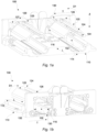
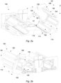
- FIG. 1a and 2a perspective front views of two package holding assemblies 100 are illustrated.
- FIG. 1b and 2b perspective rear views of two package holding assemblies 100, shown in Fig. 1a and 2a , are respectively illustrated.
- Each package holding assembly 100 may be used for packaging a product such as water, juice, dairy product e.g. yogurt, etc.
- the package 10 may comprise a main body 12, a neck 14 and a shoulder 11.
- the main body 12 of the package 10 may correspond to where the product e.g. a dairy product is held.
- the shoulder 11 may connect the main body 12 to the neck 14.
- the main body 12 of the package 10 may be sealable by the shoulder 11.
- the shoulder 11 may have an angle with respect to the main body 12 of the package 10.
- the shoulder 11 and the neck 14 may comprise a plastic material.
- the neck 14 may correspond to an upper end of the package 10.
- the neck 14 may be configured to receive a cap/lid 18.
- the shoulder 11 may connect the main body 12 to the neck 14.
- the portion 16 of the main body 12 of the package 10 may be a portion/part 16 of the package where the shoulder 11 of the package 10 meets the main body 12.
- the package holding assembly 100 may be used for packaging products into packages 10 that can hold a product volume of 250 ml to 2000 ml, or even more.
- the package holding assembly 100 comprises a base unit 110.
- the base unit 110 is arranged along a longitudinal direction L.
- the base unit 110 extends from a first end 114 of the base unit 110 to a second end 116 of the base unit 110 along the longitudinal direction L.
- the base unit 110 may have a length in the range of, for example, 10 to 30 cm along the longitudinal direction L.
- the base unit 110 may extend from a side of the base unit 110 to another side of the base unit 110 along the transverse direction T.
- the base unit 110 may comprise various parts/portions.
- the base unit 110 may be made of any material suitable for packaging a product.
- the package holding assembly 100 comprises a movable cover unit 120.
- the movable cover unit 120 is arranged along the longitudinal direction L.
- the movable cover unit 120 extends from a first end 124 of the movable cover unit 120 to a second end 126 of the movable cover unit 120 along the longitudinal direction L.
- the movable cover unit 120 may extend from a side of the movable cover unit 120 to another side of the movable cover unit 120 along the transverse direction T.
- the movable cover unit 120 may comprise various parts/portions.
- the movable cover unit 120 may be made of any material suitable for packaging a product.
- the package holding assembly 100 comprises a holding unit 130.
- the holding unit 130 is arranged at the second end 116 of the base unit 110.
- the holding unit 130 may comprise a first end E1.
- the first end E1 of the holding unit 130 may be configured to be attached to the second end 116 of the base unit 110.
- the holding unit 130 is arranged along a transverse direction T.
- the holding unit 130 may comprise a second end E2.
- the holding unit 130 may extend from the first end E1 to the second end E2 along a third direction Z.
- the third direction Z may be a direction opposite/perpendicular to the transverse direction T and to the longitudinal direction L.
- the holding unit 130 may comprise a first side 132.
- the holding unit 130 may comprise a second side 134.
- the movable cover unit 120 is configured to pivotably rotate in a first direction D1 around the longitudinal direction L to cover the base unit 110 to form a closed state.
- the movable cover unit 120 is configured to pivotably rotate to a left side and downward to form a closed state.
- the left side is shown to be along the transverse direction T.
- the downward is shown to be along the third direction Z.
- the movable cover unit 120 may be configured to pivotably rotate in a second direction D2 around an axis that is parallel to the longitudinal direction L, to uncover the base unit 110 to form an open state.
- the movable cover unit 120 is configured to pivotably rotate to a right side and upward to uncover the base unit 110 to form the open state.
- the right side is shown to be opposite to the transverse direction T.
- the upward is shown to be opposite to the third direction Z.
- the second direction D2 may be opposite to the first direction D1.
- the movable cover unit 120 in the closed state, is configured to cover the base unit 110.
- the movable cover unit 120 and the base unit 110 are configured to form a cavity 102.
- the cavity 102 is configured to receive and support a package 10.
- a portion of the base unit 110 and the first end 124 of the movable cover unit 120 are configured to form an inlet 104 for the cavity 102.
- the inlet 104 is shown by dashed lines in Fig. 1a .
- the package holding assembly 100 is configured to receive 310 a main body 12 of the package 10 via the inlet 104 of the cavity 102.
- the package holding assembly 100 may be configured to receive 310 the package 10 from the upper end of the package comprising the neck 14 via the inlet 104 of the cavity 102 into the cavity 102.
- the cavity 102 formed by the movable cover unit 120 and the base unit 110 in the closed state, may correspond to the main body 12 of the package 10.
- a shape of the cavity 102 may correspond to a shape of the main body 12 of the package 10.
- dimensions of the cavity 102 along the longitudinal direction L and the transverse direction T may respectively correspond a length and a width of the main body 12 of the package 10.
- the main body 12 of the package 10 is moved 320 inside the cavity 102 along the longitudinal direction L towards the opening 132 of the holding unit 130.
- the holding unit 130 is configured to receive the portion 16 of the main body 12 of the package 10 via the opening 132.
- the holding unit 130 is configured to fixedly hold 320 a periphery of the portion 16 of the main body 12 of the package 10.
- the first side 132 of the holding unit 130 may face the cavity 102.
- the second side 134 of the holding unit 130 may not face the cavity 102.
- the main body 12 of the package 10 In the closed state and when the holding unit 130 fixedly holds the periphery of the portion 16 of the main body 12 of the package 10, the main body 12 of the package 10 may be arranged on the first side 132.
- the neck 14 of the package 10 In the closed state and when the holding unit 130 fixedly holds the periphery of the portion 16 of the main body 12 of the package 10, the neck 14 of the package 10 may be arranged on the second side 134 of the holding unit 130. In the other words, when the portion 16 of the main body 12 of the package 10 is arranged at the second position P2, the neck 14 of the package 10 may be arranged on the second side 134 of the holding unit 130.
- the holding unit 130 may consist of one piece.
- the holding unit 130 comprises an opening 132.
- the opening 132 of the holding unit 130 may have a first size S1 in the range of 63 to 83 mm, alternatively in the range of 71 to 75 mm, along the transverse direction T.
- the holding unit 130 may have a second size S2/a first depth at its first end E1 along the longitudinal direction L.
- the second size S2/the first depth may be in the range of 7 to 13 mm, alternatively in the range of 9 to 11 mm.
- the holding unit 130 may have a third size S3/a second depth at its second end E2 along the longitudinal direction L.
- the third size S3/a second depth may be in the range of 25 to 45 mm, alternatively in the range of 32 to 38 mm.
- the opening 132 of the holding unit 130 may have a rounded rectangular shape.
- the inner corners of the opening 132 of the holding unit 130 may be rounded.
- the rounded rectangular shape of the opening 132 of the holding unit 130 may comprise corners having a radius R in the range of 12 to 22 mm, alternatively in the range of 16 to 18 mm.
- the opening 132 of the holding unit 130 may comprise a chamfered edge 140.
- the chamfered edge 140 may face the cavity 102.
- the chamfered edge 140 may be concavely rounded.
- the opening 132 of the holding unit 130 may comprise four sections 141, 142, 143, and 144 arranged to fixedly hold 320 the periphery of the portion 16 of the main body 12.
- the four sections 141, 142, 143, and 144 may have a similar size/dimension along the longitudinal direction.
- the four sections 141, 142, 143, and 144 may have different sizes/dimensions along the longitudinal direction.
- the opening 132 of the holding unit 130 may comprise four recesses 145, 146, 147, and 148.
- the four recesses 145, 146, 147, and 148 may be arranged to separate the four sections 141, 142, 143, and 144 from each other.
- the four recesses 145, 146, 147, and 148 may have a similar size/dimension along the longitudinal direction.
- the four recesses 145, 146, 147, and 148 may have different sizes/dimensions along the longitudinal direction.
- the movable cover unit 120 may comprise a portion 125, 127, 129.
- the portion 125, 127, 129 may extend along the transverse direction T at the second end 126 of the movable cover unit 120.
- the portion 125, 127, 129 may comprise several portions 125, 127, 129.
- the portion 125, 127, 129 may correspond to the holing unit 130.
- a shape of the portion 125, 127, 129 may correspond to the shape of the holding unit 130.
- the portion 125, 127, 129 of the movable cover unit 120 In the closed state, the portion 125, 127, 129 of the movable cover unit 120 may be configured to abut the second end E2 of the holding unit 130 at the second end 126 of the movable cover unit 120.
- the capping station 200 may be one station of a packaging machine.
- the packaging machine may comprise other stations such as a package folding station, a neck/lid forming station arranged downstream the capping station 200.
- the capping station 200 comprises a package holding assembly 100.
- the package holding assembly 100 may be any of the package holding assemblies, as shown in Figs. 1-4 and defined above.
- the package holding assembly 100 may be configured to receive the package 10 such that a lower end of the package 10 may be arranged at the first position P1.
- the first position P1 may correspond to a first end 114 of the base unit 110 along the longitudinal direction L.
- the package holding assembly 100 may be configured to receive the package 10 such that the portion 16 of the package 10 may be arranged at the third position P3.
- the third position P3 may correspond to a position of the inlet 104 of the cavity 102 of the package holding assembly 100 in the closed state.
- the third position P3 may be arranged with a distance from the first position P1 along the longitudinal direction L.
- the package holding assembly 100 may be configured to receive the package 10 such that the portion 16 of the package 10 may not be arranged at the third position P3.
- the package holding assembly 100 may be configured to receive the package 10 such that the portion 16 of the package 10 may be arranged inside the cavity 102.
- the capping station 200 comprises a pusher 220.
- the pusher 220 is arranged at the first end 114 of the base unit 110 of the package holding assembly 100.
- the pusher 220 is configured to push 310 a package 10 along the longitudinal direction L, into the cavity 104 until the holding unit 130 receives the portion 16 of the main body 12.
- the holding unit 130 is configured to fixedly hold 320 the periphery of the portion 16 of the main body 12.
- the pusher 220 may be configured to push 310 the package 10 along the longitudinal direction L, into the cavity 104 until the portion 16 of the main body 12 of the package 10 is arranged at the second position P2.
- the second position P2 may correspond to the position of the holding unit 130, along the longitudinal direction L.
- the pusher 220 may be any conventional and commercially available pusher 220 suitable for the capping station 200.
- the capping station 200 comprises a cap applicator unit 210.
- the cap applicator unit 210 is configured to apply 330 a cap 18 on the neck 14 of the package 10.
- the cap applicator unit 210 is configured to apply 330 a cap 18 on the neck 14 of the package 10 when the holding unit 130 fixedly holds 320 the periphery of said portion 16.
- the cap applicator unit 210 may be any conventional and commercially available cap applicator unit 210 suitable for the capping station 200.
- the packaging machine may comprise a package sterilisation unit e.g. a hygienic chamber.
- the hygienic chamber may be arranged upstream the capping station 200.
- the packages may be sent from the capping station 200 to the hygienic chamber.
- the packages In the hygienic chamber, the packages may be exposed to a high-efficiency particulate air (HEPA) filtered environment.
- the packages may also be exposed to an ultraviolet (UV) light in the hygienic chamber.
- the packaging machine may comprise a filling station arranged upstream the hygienic chamber.
- the packages may be filled with the product in the filing product e.g. dairy product.
- the packages may be exposed to the HEPA filtered environment in the filing station.
- the packaging machine may comprise a sealing station arranged upstream the filing station. The packages may be sealed in the sealing station.
- a method 300 of applying 330 a cap 18 on a neck 14 of a package 10 comprises the step of pushing 310 a package 10 into a package holding assembly 100.
- the step of pushing 310 may be performed using a pusher 220 of a capping station 200, as defined in relation to Fig. 5 above.
- the method 300 comprises the step of fixedly holding 320 with the holding unit 130 of the package holding assembly 100 a periphery of a portion 16 of the main body 12 of the package 10.
- the holding unit 130 of the package holding assembly 100 may be similar to the holding unit 130 defined in relation to Figs. 1-5 .
- the method 300 comprises the step of applying 330 a cap 18 on a neck 14 of the package 10.
- the step of applying 330 the cap 18 on the neck 14 of the package 10 may be performed using the cap applicator unit 210, as defined in relation to Fig. 5 .
Landscapes
- Engineering & Computer Science (AREA)
- Mechanical Engineering (AREA)
- Packages (AREA)
Abstract
A package holding assembly (100) having a base unit (110), a movable cover unit (120) and a holding unit (130) that has an opening (132). The movable cover unit (120) is configured to pivotably rotate to cover the base unit (110) to form a closed state where it covers the base unit (110) to form a cavity (102) for a package (10). A main body (12) of the package (10) is received via the inlet (104) of the cavity (102), where the main body (12) of the package (10) is moved (320) inside the cavity (102) along a longitudinal direction (L) towards the opening (132) of the holding unit (130), and wherein the holding unit (130) is configured to receive a portion (16) of the main body (12) of the package (10) via the opening (132), and to fixedly hold (320) a periphery of the portion (16) of the main body (12) of the package (10).
Description
- The invention relates to a package holding assembly, a capping station for a filing machine, and a method of applying a cap on a neck of a package.
- Packaging machines are industrial devices designed to efficiently and consistently package products into various types of containers or packaging materials. These machines play a critical role in the manufacturing and distribution of products across a wide range of industries. Examples of such products are beverage and dairy products. A packaging machine may comprise different units such as a package forming unit, a package sterilisation unit and a package filing unit.
- The packaging machines have developed significantly during the past years e.g. in terms of automation, hygiene and safety. However, the interplay of tolerances within the packaging machine may result in significant variations which may vary from one machine to another machine. Thus, there is a need to further improve the packaging machines in terms of consistency and accuracy.
- Conventional packaging machines comprises a capping station. The capping station comprises a package holding unit configured to hold a package while a cap is being applied on a neck of the package. Such package holding units typically comprise several parts. An example of drawbacks of such package holding units is that the parts of the holding unit need to be carefully attached to one another and also to other parts of the capping station to hold the package in place, as a tolerance chain of the parts of the holding unit may lead to significant variations. Such variations may vary from one machine to another machine. Such variations may e.g. result in that the holding unit may not hold the packaging at a fixed position while a cap is being applied on the neck of the package. Another example of drawbacks of such package holding units is that the position of the parts of the holding unit need to be calibrated regularly.
- It is an object of the invention to at least partly overcome one or more of the above-identified limitations of the prior art. In particular, it is an object to provide an improved package holding assembly and an improved capping station for a filing machine of a packaging machine that allows for a precise positioning of a package in a consistent, reliable and accurate manner e.g. when a cap is being applied on the neck of the package. It is another object of the invention to provide an improved method of applying the cap on the neck of a package.
- To solve these objects a package holding assembly is provided. The package holding assembly comprises a base unit. The base unit is arranged along a longitudinal direction and extends from a first end of the base unit to a second end of the base unit along the longitudinal direction. The package holding assembly further comprises a movable cover unit. The movable cover unit is arranged along the longitudinal direction and extends from a first end of the movable cover unit to a second end of the movable cover unit along the longitudinal direction. The package holding assembly further comprises a holding unit. The holding unit is arranged along a transverse direction at the second end of the base unit. The holding unit comprises an opening. The movable cover unit is configured to pivotably rotate in a first direction around the longitudinal direction to cover the base unit to form a closed state. In the closed state, the movable cover unit is configured to cover the base unit. The movable cover unit and the base unit are configured to form a cavity to receive and support a package. A portion of the base unit and the first end of the movable cover unit are configured to form an inlet for the cavity. In the closed state, the package holding assembly is configured to receive a main body of the package via the inlet of the cavity. The main body of the package is moved inside the cavity along the longitudinal direction towards the opening of the holding unit. The holding unit is configured to receive a portion of the main body of the package via the opening, and to fixedly hold a periphery of the portion of the main body of the package.
- The holding unit is advantageous in that it allows for fixedly holding/maintaining/supporting the portion of the main body of the package while maintaining/preserving a shape and position of the portion of the main body of the package. Thus, the holding unit prevents, or at least mitigates, movement of the main body of the package. Examples of the movement of the main body of the package are movements along the longitudinal direction, opposite to the longitudinal direction, along the transverse direction and/or opposite to the transverse direction. In addition, the holding unit prevents, or at least mitigates, rotation of the main body of the package. Examples of the rotation of the main body of the package are rotation along the first direction and/or along the second direction. The holding unit is further advantageous in that it allows for fixedly holding/maintaining/supporting the portion of the main body of the package while a cap is being applied on a neck of the package. Thus, the holding unit allows for fixedly holding the periphery of the portion of the main body of the package in an accurate, reliable and consistent manner e.g. when a cap is being applied on the package.
- The package may comprise a main body, a neck and a shoulder. The main body of the package may correspond to where the product e.g. a dairy product is held. The neck may correspond to an upper part of the package. The neck may be configured to receive a cap/lid. The shoulder may connect the main body to the neck. The portion of the main body of the package may be a portion/part of the package where the shoulder of the package meets the main body. The package may comprise an upper end and a lower end. An upper end of the package may correspond to the end of the package comprising the neck. The lower end of the package may correspond to the other end of the package not comprising the neck. The holding assembly may receive the package from the upper end of the package comprising the neck.
- The base unit is arranged along the longitudinal direction and extends from the first end of the base unit to the second end of the base unit along the longitudinal direction. The first end and the second end of the base unit may be arranged opposite to each other along the longitudinal direction. The first end of the base unit may be arranged at a first position along the longitudinal direction. The second end of the base unit may be arranged at a second position along the longitudinal direction. The second position may correspond to a position of the holding unit, along the longitudinal direction.
- The movable cover unit is arranged along the longitudinal direction and extends from the first end of the movable cover unit to the second end of the movable cover unit along the longitudinal direction. The first end of the movable cover unit may be arranged at a third position. The third position may correspond to a position of the inlet of the cavity of the package holding assembly in the closed state. The second end of the movable cover unit may be arranged at the second position along the longitudinal direction. The second position may correspond to the position of the holding unit, along the longitudinal direction.
- The holding unit may be a guide or a holding ring suitable for fixedly holding the periphery of the portion of the main body of the package. The holding unit may comprise two sides. A first side of the holding unit may face the cavity. A second side of the holding unit may not face the cavity. In the closed state and when the holding unit fixedly holds the periphery of the portion of the main body of the package, the main body of the package may be arranged on the first side and the neck of the package may be arranged on the second side of the holding unit.
- The portion of the base unit and the first end of the movable cover unit are configured to form the inlet for the cavity. Thus, the main body of the package may enter the cavity via the inlet from the upper end of the package comprising the neck. The main body of the package may leave the cavity via the opening of the holding unit. Thus, the opening of the holding unit may form an outlet for the cavity.
- By the longitudinal direction is hereby meant a direction parallel to the direction of movement of the main body of the package inside the cavity of the packaging holding assembly in the closed state. By the transverse direction is hereby meant a direction opposite/perpendicular to the longitudinal direction.
- Two package holding assemblies may be arranged side by side. Thereby, they may allow for providing double capacity. In addition, they may allow for performing maintenance on one package holding assembly without stopping a production line on the other package holding assembly.
- In some embodiments, the holding unit consists of one piece. Thereby, it may allow for an even more precise and accurate positioning of the holding unit inside the package holding assembly, as installation/positioning/calibration of the holding unit may not require attaching parts of the holding unit together. This in turn may allow for preventing or at least mitigating variations due to interplay of tolerances of different parts of the holding unit. Thus, the one-piece holding unit may allow for fixedly holding the periphery of the portion of the main body of the package in an accurate, reliable and consistent manner. In addition, the one-piece holding unit may allow for, or at least facilitate, providing consistent and uniform packaging holding assemblies having no variations, or at least reduced variations, with respect to one another. The one-piece holding unit may also allow for producing/manufacturing the holding unit in a simple, user-friendly and cost-effective manner.
- In some embodiments, the opening of the holding unit has a rounded rectangular shape. The rounded rectangular shape of the opening of the holding unit may correspond to a shape of the main body of the package. The inner rounded corners of the rectangular shape may avoid/prevent, or at least mitigate, damaging the main body of the package. This may in turn provide an improved package holding assembly in terms of reliability while maintaining hygiene. By the rounded rectangular shape is hereby meant a rectangular shape with inner rounded corners.
- In some embodiments, the rounded rectangular shape of the opening of the holding unit comprises corners having a radius in the range of 12 to 22 mm. The rounded rectangular shape of the opening of the holding unit may comprise corners having any radius suitable for fixedly holding the periphery of the portion of the main body of the package.
- In some embodiments, the opening of the holding unit comprises a chamfered edge that faces the cavity. Thus, the chamfered edge of the opening of the holding unit may avoid/prevent, or at least mitigate, damaging the main body of the package. This may in turn provide an even more reliable package holding assembly.
- In some embodiments, the chamfered edge is concavely rounded. Thus, the chamfered edge may not have any sharp corners and may hence not damage the main body of the package.
- In some embodiments, the opening of the holding unit comprises four sections arranged to fixedly hold the periphery of the portion of the main body. In some embodiments, the opening of the holding unit comprises four recesses arranged to separate the four sections from each other.
- The four sections and/or the four recesses may allow for an enhanced grip of the holding unit while providing a reduced weight. The four sections and/or the four recesses may allow for optimizing a material usage of the holding unit and may thus allow for reducing a production cost of the holding unit. The four sections and/or the four recesses may further allow for structural reinforcement, vibration damping and improving durability of the holding unit.
- In some embodiments, the opening of the holding unit has a first size in the range of 63 to 83 mm along the transverse direction. The opening of the holding unit may have any sizes suitable for fixedly holding the periphery of the portion of the main body of the package, corresponding to the size of the package.
- In some embodiments, a first end of the holding unit is configured to be attached to the second end of the base unit. The movable cover unit may comprise a portion extending along the transverse direction at the second end of the movable cover unit. In the closed state, the portion of the movable cover unit may be configured to abut a second end of the holding unit at the second end of the movable cover unit.
- Thereby, the portion of the movable cover unit may facilitate the holding unit fixedly holding the periphery of the portion of the main body of the package. The portion of the movable cover unit may comprise several portions/parts. The several portions/parts of the portion of the movable cover unit may be designed and manufactured in any desired shape and size. The several portions/parts of the portion of the movable cover unit may correspond to the shape of the holding unit.
- The holding unit may extend from the first end to the second end along a third direction. The third direction may be a direction perpendicular to the transverse and the longitudinal direction. The second end of the holding unit may be arranged opposite to the first end of the holding unit along the third direction. The first end of the holding unit may correspond to a first side of a periphery of the holding unit. The second end of the holding unit may correspond to a second side of the periphery of the holding unit opposite to the first side.
- In some embodiments, a second size of the first end of the holding unit along the longitudinal direction is in the range of 7 to 13 mm. In some embodiments, a third size of the second end of the holding unit along the longitudinal direction is in the range of 25 to 45 mm. The third size of the second end of the holding unit along the longitudinal direction may correspond to a size of the portion of the movable cover unit along the longitudinal direction. The third size of the second end of the holding unit along the longitudinal direction may not correspond to a size of the portion of the movable cover unit along the longitudinal direction.
- In some embodiments, the movable cover unit is configured to pivotably rotate in a second direction around an axis that is parallel to the longitudinal direction, to uncover the base unit to form an open state.
- Thus, the open state may allow for performing maintenance, calibration or cleaning in a convenient and user-friendly manner. The second direction may be opposite to the first direction. For instance, the movable cover unit may pivotably rotate to a right side and upward when viewed along the longitudinal direction to uncover the base unit to form an open state. The movable cover unit may pivotably rotate to a left side and downward when viewed along the longitudinal direction to cover the base unit to form the closed state.
- According to a second aspect of the invention, a capping station for a filing machine is provided. The capping station comprises a package holding assembly according to the first aspect of the invention. The capping station further comprises a pusher arranged at the first end of the base unit of the package holding assembly and configured to push a package along the longitudinal direction into the cavity until the holding unit receives the portion of the main body and fixedly holds the periphery of the portion. The capping station further comprises a cap applicator unit configured to apply a cap on the neck of the package, when the holding unit fixedly holds the periphery of said portion.
- The pusher allows the holding unit to receive the portion of the main body and fixedly holds the periphery of the portion. The cap applicator unit allows for applying the cap on the neck of the package, when the holding unit fixedly holds the periphery of the portion. The second aspect generally presents the same or similar advantages as the first aspect of the invention.
- According to a third aspect of the invention, a method of applying a cap on a neck of a package is provided. The method comprises the step of pushing a package into a package holding assembly according to the first or the second aspect of the invention. The method further comprises the step of fixedly holding, with the holding unit of the package holding assembly, a periphery of a portion of the main body of the package, and applying a cap on a neck of the package. The third aspect generally presents the same or similar advantages as the first or the second aspect of the invention.
- Still other objectives, features, aspects and advantages of the invention will appear from the following detailed description as well as from the drawings.
- Embodiments of the invention will now be described, by way of example, with reference to the accompanying schematic drawings, in which
-
Fig. 1a illustrates a perspective front view of two package holding assemblies which are arranged side by side when both are in a closed state. -
Fig. 1b illustrates a perspective rear view of two package holding assemblies shown inFig. 1a . -
Fig. 2a illustrates a perspective front view of two package holding assemblies shown inFig. 1a when one is in a closed state and another one is in open state. -
Fig. 2b illustrates a perspective rear view of two package holding assemblies shown inFig. 2a . -
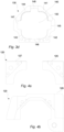
Fig. 3a, b, c andd illustrate a perspective rear view, a side view, a rear view, and a front view of a holding unit of a package holding assembly, respectively. -
Fig. 4a and 4b illustrate front views of portions of a movable cover unit of a package holding assembly. -
Fig. 5 schematically illustrates a capping station for a filing machine which comprises a package holding assembly. -
Fig. 6 schematically shows steps of a method of applying a cap on a neck of a package. - With reference to
Fig. 1a and2a , perspective front views of twopackage holding assemblies 100 are illustrated. With reference toFig. 1b and2b , perspective rear views of twopackage holding assemblies 100, shown inFig. 1a and2a , are respectively illustrated. Eachpackage holding assembly 100 may be used for packaging a product such as water, juice, dairy product e.g. yogurt, etc. - The
package 10 may comprise amain body 12, aneck 14 and ashoulder 11. Themain body 12 of thepackage 10 may correspond to where the product e.g. a dairy product is held. Theshoulder 11 may connect themain body 12 to theneck 14. Themain body 12 of thepackage 10 may be sealable by theshoulder 11. Theshoulder 11 may have an angle with respect to themain body 12 of thepackage 10. Theshoulder 11 and theneck 14 may comprise a plastic material. Theneck 14 may correspond to an upper end of thepackage 10. Theneck 14 may be configured to receive a cap/lid 18. Theshoulder 11 may connect themain body 12 to theneck 14. Theportion 16 of themain body 12 of thepackage 10 may be a portion/part 16 of the package where theshoulder 11 of thepackage 10 meets themain body 12. Thepackage holding assembly 100 may be used for packaging products intopackages 10 that can hold a product volume of 250 ml to 2000 ml, or even more. - The
package holding assembly 100 comprises abase unit 110. Thebase unit 110 is arranged along a longitudinal direction L. Thebase unit 110 extends from afirst end 114 of thebase unit 110 to asecond end 116 of thebase unit 110 along the longitudinal direction L. Thebase unit 110 may have a length in the range of, for example, 10 to 30 cm along the longitudinal direction L. Thebase unit 110 may extend from a side of thebase unit 110 to another side of thebase unit 110 along the transverse direction T. Thebase unit 110 may comprise various parts/portions. Thebase unit 110 may be made of any material suitable for packaging a product. - The
package holding assembly 100 comprises amovable cover unit 120. Themovable cover unit 120 is arranged along the longitudinal direction L. Themovable cover unit 120 extends from afirst end 124 of themovable cover unit 120 to asecond end 126 of themovable cover unit 120 along the longitudinal direction L. Themovable cover unit 120 may extend from a side of themovable cover unit 120 to another side of themovable cover unit 120 along the transverse direction T. Themovable cover unit 120 may comprise various parts/portions. Themovable cover unit 120 may be made of any material suitable for packaging a product. - The
package holding assembly 100 comprises a holdingunit 130. The holdingunit 130 is arranged at thesecond end 116 of thebase unit 110. The holdingunit 130 may comprise a first end E1. The first end E1 of the holdingunit 130 may be configured to be attached to thesecond end 116 of thebase unit 110. The holdingunit 130 is arranged along a transverse direction T. The holdingunit 130 may comprise a second end E2. The holdingunit 130 may extend from the first end E1 to the second end E2 along a third direction Z. The third direction Z may be a direction opposite/perpendicular to the transverse direction T and to the longitudinal direction L. The holdingunit 130 may comprise afirst side 132. The holdingunit 130 may comprise asecond side 134. - With reference to
Fig. 1a and 1b , themovable cover unit 120 is configured to pivotably rotate in a first direction D1 around the longitudinal direction L to cover thebase unit 110 to form a closed state. InFig. 1a , themovable cover unit 120 is configured to pivotably rotate to a left side and downward to form a closed state. InFig. 1a , the left side is shown to be along the transverse direction T. InFig. 1a , the downward is shown to be along the third direction Z. - With reference to
Fig. 2a and 2b , themovable cover unit 120 may be configured to pivotably rotate in a second direction D2 around an axis that is parallel to the longitudinal direction L, to uncover thebase unit 110 to form an open state. InFig. 2a , themovable cover unit 120 is configured to pivotably rotate to a right side and upward to uncover thebase unit 110 to form the open state. InFig. 2a , the right side is shown to be opposite to the transverse direction T. InFig. 2a , the upward is shown to be opposite to the third direction Z. The second direction D2 may be opposite to the first direction D1. - With reference to
Fig. 1a and 1b , in the closed state, themovable cover unit 120 is configured to cover thebase unit 110. In the closed state, themovable cover unit 120 and thebase unit 110 are configured to form acavity 102. Thecavity 102 is configured to receive and support apackage 10. A portion of thebase unit 110 and thefirst end 124 of themovable cover unit 120 are configured to form aninlet 104 for thecavity 102. Theinlet 104 is shown by dashed lines inFig. 1a . In the closed state, thepackage holding assembly 100 is configured to receive 310 amain body 12 of thepackage 10 via theinlet 104 of thecavity 102. In the closed state, thepackage holding assembly 100 may be configured to receive 310 thepackage 10 from the upper end of the package comprising theneck 14 via theinlet 104 of thecavity 102 into thecavity 102. Thecavity 102, formed by themovable cover unit 120 and thebase unit 110 in the closed state, may correspond to themain body 12 of thepackage 10. For example, a shape of thecavity 102 may correspond to a shape of themain body 12 of thepackage 10. Another example, dimensions of thecavity 102 along the longitudinal direction L and the transverse direction T may respectively correspond a length and a width of themain body 12 of thepackage 10. - The
main body 12 of thepackage 10 is moved 320 inside thecavity 102 along the longitudinal direction L towards the opening 132 of the holdingunit 130. The holdingunit 130 is configured to receive theportion 16 of themain body 12 of thepackage 10 via theopening 132. The holdingunit 130 is configured to fixedly hold 320 a periphery of theportion 16 of themain body 12 of thepackage 10. - The
first side 132 of the holdingunit 130 may face thecavity 102. Thesecond side 134 of the holdingunit 130 may not face thecavity 102. In the closed state and when the holdingunit 130 fixedly holds the periphery of theportion 16 of themain body 12 of thepackage 10, themain body 12 of thepackage 10 may be arranged on thefirst side 132. In the closed state and when the holdingunit 130 fixedly holds the periphery of theportion 16 of themain body 12 of thepackage 10, theneck 14 of thepackage 10 may be arranged on thesecond side 134 of the holdingunit 130. In the other words, when theportion 16 of themain body 12 of thepackage 10 is arranged at the second position P2, theneck 14 of thepackage 10 may be arranged on thesecond side 134 of the holdingunit 130. - With reference to
Figs. 3a-3d , a perspective rear view, a side view, a rear view, and a front view of a holdingunit 130 are shown, respectively. The holdingunit 130 may consist of one piece. The holdingunit 130 comprises anopening 132. Theopening 132 of the holdingunit 130 may have a first size S1 in the range of 63 to 83 mm, alternatively in the range of 71 to 75 mm, along the transverse direction T. The holdingunit 130 may have a second size S2/a first depth at its first end E1 along the longitudinal direction L. The second size S2/the first depth may be in the range of 7 to 13 mm, alternatively in the range of 9 to 11 mm. The holdingunit 130 may have a third size S3/a second depth at its second end E2 along the longitudinal direction L. The third size S3/a second depth may be in the range of 25 to 45 mm, alternatively in the range of 32 to 38 mm. - The
opening 132 of the holdingunit 130 may have a rounded rectangular shape. The inner corners of theopening 132 of the holdingunit 130 may be rounded. The rounded rectangular shape of theopening 132 of the holdingunit 130 may comprise corners having a radius R in the range of 12 to 22 mm, alternatively in the range of 16 to 18 mm. Theopening 132 of the holdingunit 130 may comprise achamfered edge 140. Thechamfered edge 140 may face thecavity 102. Thechamfered edge 140 may be concavely rounded. Theopening 132 of the holdingunit 130 may comprise foursections portion 16 of themain body 12. The foursections sections opening 132 of the holdingunit 130 may comprise fourrecesses recesses sections recesses recesses - With reference to
Figs. 4a and 4b , themovable cover unit 120 may comprise aportion portion second end 126 of themovable cover unit 120. Theportion several portions portion holing unit 130. For instance, a shape of theportion unit 130. In the closed state, theportion movable cover unit 120 may be configured to abut the second end E2 of the holdingunit 130 at thesecond end 126 of themovable cover unit 120. - With reference to
Fig. 5 , acapping station 200 for a filing machine is illustrated. Thecapping station 200 may be one station of a packaging machine. The packaging machine may comprise other stations such as a package folding station, a neck/lid forming station arranged downstream thecapping station 200. Thecapping station 200 comprises apackage holding assembly 100. Thepackage holding assembly 100 may be any of the package holding assemblies, as shown inFigs. 1-4 and defined above. Thepackage holding assembly 100 may be configured to receive thepackage 10 such that a lower end of thepackage 10 may be arranged at the first position P1. The first position P1 may correspond to afirst end 114 of thebase unit 110 along the longitudinal direction L. Thepackage holding assembly 100 may be configured to receive thepackage 10 such that theportion 16 of thepackage 10 may be arranged at the third position P3. The third position P3 may correspond to a position of theinlet 104 of thecavity 102 of thepackage holding assembly 100 in the closed state. The third position P3 may be arranged with a distance from the first position P1 along the longitudinal direction L. Alternatively, thepackage holding assembly 100 may be configured to receive thepackage 10 such that theportion 16 of thepackage 10 may not be arranged at the third position P3. For example, thepackage holding assembly 100 may be configured to receive thepackage 10 such that theportion 16 of thepackage 10 may be arranged inside thecavity 102. - The
capping station 200 comprises apusher 220. Thepusher 220 is arranged at thefirst end 114 of thebase unit 110 of thepackage holding assembly 100. Thepusher 220 is configured to push 310 apackage 10 along the longitudinal direction L, into thecavity 104 until the holdingunit 130 receives theportion 16 of themain body 12. The holdingunit 130 is configured to fixedly hold 320 the periphery of theportion 16 of themain body 12. Thepusher 220 may be configured to push 310 thepackage 10 along the longitudinal direction L, into thecavity 104 until theportion 16 of themain body 12 of thepackage 10 is arranged at the second position P2. The second position P2 may correspond to the position of the holdingunit 130, along the longitudinal direction L. Thepusher 220 may be any conventional and commerciallyavailable pusher 220 suitable for thecapping station 200. - The
capping station 200 comprises acap applicator unit 210. Thecap applicator unit 210 is configured to apply 330 a cap 18 on theneck 14 of thepackage 10. Thecap applicator unit 210 is configured to apply 330 a cap 18 on theneck 14 of thepackage 10 when the holdingunit 130 fixedly holds 320 the periphery of saidportion 16. Thecap applicator unit 210 may be any conventional and commercially availablecap applicator unit 210 suitable for thecapping station 200. - The packaging machine may comprise a package sterilisation unit e.g. a hygienic chamber. The hygienic chamber may be arranged upstream the
capping station 200. The packages may be sent from thecapping station 200 to the hygienic chamber. In the hygienic chamber, the packages may be exposed to a high-efficiency particulate air (HEPA) filtered environment. The packages may also be exposed to an ultraviolet (UV) light in the hygienic chamber. The packaging machine may comprise a filling station arranged upstream the hygienic chamber. The packages may be filled with the product in the filing product e.g. dairy product. The packages may be exposed to the HEPA filtered environment in the filing station. The packaging machine may comprise a sealing station arranged upstream the filing station. The packages may be sealed in the sealing station. - With reference to
Fig. 6 , amethod 300 of applying 330 a cap 18 on aneck 14 of apackage 10 is provided. Themethod 300 comprises the step of pushing 310 apackage 10 into apackage holding assembly 100. The step of pushing 310 may be performed using apusher 220 of acapping station 200, as defined in relation toFig. 5 above. Themethod 300 comprises the step of fixedly holding 320 with the holdingunit 130 of the package holding assembly 100 a periphery of aportion 16 of themain body 12 of thepackage 10. The holdingunit 130 of thepackage holding assembly 100 may be similar to the holdingunit 130 defined in relation toFigs. 1-5 . Themethod 300 comprises the step of applying 330 a cap 18 on aneck 14 of thepackage 10. The step of applying 330 the cap 18 on theneck 14 of thepackage 10 may be performed using thecap applicator unit 210, as defined in relation toFig. 5 . - From the description above follows that, although various embodiments of the invention have been described and shown, the invention is not restricted thereto, but may also be embodied in other ways within the scope of the subject-matter defined in the following claims.
Claims (14)
- A package holding assembly (100) comprising:a base unit (110) arranged along a longitudinal direction (L) and extending from a first end (114) of the base unit (110) to a second end (116) of the base unit (110) along the longitudinal direction (L),a movable cover unit (120) arranged along the longitudinal direction (L) and extending from a first end (124) of the movable cover unit (120) to a second end (126) of the movable cover unit (120) along the longitudinal direction (L),a holding unit (130) arranged along a transverse direction (T) at the second end (116) of the base unit (110), the holding unit (130) comprising an opening (132),wherein the movable cover unit (120) is configured to pivotably rotate in a first direction (D1) around the longitudinal direction (L) to cover the base unit (110) to form a closed state where in the closed state, the movable cover unit (120) is configured to cover the base unit (110), and where the movable cover unit (120) and the base unit (110) are configured to form a cavity (102) to receive and support a package (10), and a portion of the base unit (110) and the first end (124) of the movable cover unit (120) are configured to form an inlet (104) for the cavity (102),wherein in the closed state, the package holding assembly (100) is configured to receive (310) a main body (12) of the package (10) via the inlet (104) of the cavity (102), where the main body (12) of the package (10) is moved (320) inside the cavity (102) along the longitudinal direction (L) towards the opening (132) of the holding unit (130), andwherein the holding unit (130) is configured to receive a portion (16) of the main body (12) of the package (10) via the opening (132), and to fixedly hold (320) a periphery of the portion (16) of the main body (12) of the package (10).
- The package holding assembly (100) according to claim 1, wherein the holding unit (130) consists of one piece.
- The package holding assembly (100) according to any of the preceding claims, wherein the opening (132) of the holding unit (130) has a rounded rectangular shape.
- The package holding assembly (100) according to claim 3, wherein the rounded rectangular shape of the opening (132) of the holding unit (130) comprises corners having a radius (R) in the range of 12 to 22 mm.
- The package holding assembly (100) according to any of the preceding claims, wherein the opening (132) of the holding unit (130) comprises a chamfered edge (140) that faces the cavity (102).
- The package holding assembly (100) according claim 5, wherein the chamfered edge (140) is concavely rounded.
- The package holding assembly (100) according to any of the preceding claims, wherein the opening (132) of the holding unit (130) comprises four sections (141-144) arranged to fixedly hold (320) the periphery of the portion (16) of the main body (12).
- The package holding assembly (100) according to claim 7, wherein the opening (132) of the holding unit (130) comprises four recesses (145-148) arranged to separate the four sections (141-144) from each other.
- The package holding assembly (100) according to any of the preceding claims, wherein the opening (132) of the holding unit (130) has a first size (S1) in the range of 63 to 83 mm along the transverse direction (T).
- The package holding assembly (100) according to any of the preceding claims, wherein a first end (E1) of the holding unit (130) is configured to be attached to the second end (116) of the base unit (110), wherein the movable cover unit (120) comprises a portion (125, 127, 129) extending along the transverse direction (T) at the second end (126) of the movable cover unit (120), and wherein, in the closed state, the portion (125, 127, 129) of the movable cover unit (120) is configured to abut a second end (E2) of the holding unit (130) at the second end (126) of the movable cover unit (120).
- The package holding assembly (100) according to claim 10, wherein a second size (S2) of the first end (E1) of the holding unit (130) along the longitudinal direction (L) is in the range of 7 to 13 mm, and wherein a third size (S3) of the second end (E2) of the holding unit (130) along the longitudinal direction (L) is in the range of 25 to 45 mm.
- The package holding assembly (100) according to any of the preceding claims, wherein the movable cover unit (120) is configured to pivotably rotate in a second direction (D2) around an axis that is parallel to the longitudinal direction (L), to uncover the base unit (110) to form an open state, and wherein the second direction (D2) is opposite to the first direction (D1).
- A capping station (200) for a filing machine, the capping station (200) comprising:a package holding assembly (100) according to any of the preceding claims,a pusher (220) arranged at the first end (114) of the base unit (110) of the package holding assembly (100) and configured to push (310) a package (10) along the longitudinal direction (L), into the cavity (104) until the holding unit (130) receives said portion (16) of the main body (12) and fixedly holds (320) the periphery of said portion (16), anda cap applicator unit (210) configured to apply (330) a cap (18) on the neck (14) of the package (10), when the holding unit (130) fixedly holds (320) the periphery of said portion (16).
- A method (300) of applying (330) a cap (18) on a neck (14) of a package (10), the method (300) comprising the steps of:pushing (310) a package (10) into a package holding assembly (100) according to any of the preceding claims,fixedly holding (320), with the holding unit (130) of the package holding assembly (100), a periphery of a portion (16) of the main body (12) of the package (10), andapplying (330) a cap (18) on a neck (14) of the package (10).
Applications Claiming Priority (1)
| Application Number | Priority Date | Filing Date | Title |
|---|---|---|---|
| EP23204794 | 2023-10-20 |
Publications (1)
| Publication Number | Publication Date |
|---|---|
| EP4541758A1 true EP4541758A1 (en) | 2025-04-23 |
Family
ID=88506804
Family Applications (1)
| Application Number | Title | Priority Date | Filing Date |
|---|---|---|---|
| EP24207641.2A Pending EP4541758A1 (en) | 2023-10-20 | 2024-10-18 | Package holding assembly |
Country Status (2)
| Country | Link |
|---|---|
| EP (1) | EP4541758A1 (en) |
| WO (1) | WO2025083260A1 (en) |
Citations (3)
| Publication number | Priority date | Publication date | Assignee | Title |
|---|---|---|---|---|
| WO2003070579A1 (en) * | 2002-02-19 | 2003-08-28 | Fci, Inc. | Plastic water bottle and apparatus and method to prevent bottle rotation |
| WO2009130657A1 (en) * | 2008-04-23 | 2009-10-29 | Azionaria Costruzioni Macchine Automatiche A.C.M.A. S.P.A. | A rotary conveyor comprising a grippξr mechanism |
| WO2015149988A1 (en) * | 2014-04-04 | 2015-10-08 | Tetra Laval Holdings & Finance S.A. | Unit for the application of lids of opening devices |
-
2024
- 2024-10-18 EP EP24207641.2A patent/EP4541758A1/en active Pending
- 2024-10-18 WO PCT/EP2024/079586 patent/WO2025083260A1/en active Pending
Patent Citations (3)
| Publication number | Priority date | Publication date | Assignee | Title |
|---|---|---|---|---|
| WO2003070579A1 (en) * | 2002-02-19 | 2003-08-28 | Fci, Inc. | Plastic water bottle and apparatus and method to prevent bottle rotation |
| WO2009130657A1 (en) * | 2008-04-23 | 2009-10-29 | Azionaria Costruzioni Macchine Automatiche A.C.M.A. S.P.A. | A rotary conveyor comprising a grippξr mechanism |
| WO2015149988A1 (en) * | 2014-04-04 | 2015-10-08 | Tetra Laval Holdings & Finance S.A. | Unit for the application of lids of opening devices |
Non-Patent Citations (1)
| Title |
|---|
| MILLER ALICIA: "10 best wine coolers for keeping your drinks perfectly chilled", THE INDEPENDENT, 21 September 2021 (2021-09-21), XP093143618, Retrieved from the Internet <URL:https://www.independent.co.uk/extras/indybest/house-garden/kitchen-appliances/best-wine-cooler-refrigerator-bottle-freezer-stainless-steel-uk-free-standing-a9599721.html> [retrieved on 20240320] * |
Also Published As
| Publication number | Publication date |
|---|---|
| WO2025083260A1 (en) | 2025-04-24 |
Similar Documents
| Publication | Publication Date | Title |
|---|---|---|
| EP0961733B1 (en) | A method of handling, filling and sealing packaging containers | |
| RU2768122C2 (en) | Method of making a bag with a nozzle, made with possibility of filling with a fluid product | |
| KR102021467B1 (en) | Supporting structure for concurrently supporting a plurality of containers for substances for medical, pharmaceutical or cosmetic applications as well as transport and packaging container comprising the same and process | |
| CA2251894C (en) | Flat-top container with an opening fitment | |
| US5155980A (en) | Forming device in packaging machines | |
| US6430899B1 (en) | Top sealing and creasing apparatus and method for a gable top carton | |
| AU2016328306B2 (en) | Rotary filling device for aseptic filling of pouches | |
| AU2016328308B2 (en) | Pouch assembly having a plug | |
| EP3353072B1 (en) | Pouch cleaning assembly for an aseptic filler | |
| CA3098804C (en) | Method and machine for making flexible packages with side gussets | |
| EP4541758A1 (en) | Package holding assembly | |
| US5924267A (en) | Process and a device for closing filled folded-carton packages | |
| JPH0255283B2 (en) | ||
| WO2006093688A2 (en) | Vented mascara wiper | |
| EP3279097B1 (en) | Support plate for a package suitable for a food product | |
| ES3061521T3 (en) | Method for packaging articles in boxes and packaging device operating according to such a method | |
| EP1617992B1 (en) | Device, installation and process for producing a package from a sheet of flexible material | |
| US6000195A (en) | Packaging machine with capability to convert to different carton cross-sections | |
| US20050156020A1 (en) | Folded-carton packages for holding a liquid beverage, and a method of manufacture for such folded-carton packages | |
| US7654062B2 (en) | Packaging machine for inserting an article to be packaged into a package | |
| JP7698874B2 (en) | filling packaging machine | |
| EP1471009A1 (en) | Gripper for opening devices to be applied to packages of pourable food products | |
| CN216762383U (en) | Medicine packaging line and closing device thereof | |
| CN211196881U (en) | Positioning device | |
| ITMI990913A1 (en) | LINEAR MOTOR DEVICE FOR AUTOMATIC EXPULSION OF INDIVIDUAL FILTER BAGS IN ASSOCIATION WITH OTHER PACKAGING MATERIALS |
Legal Events
| Date | Code | Title | Description |
|---|---|---|---|
| PUAI | Public reference made under article 153(3) epc to a published international application that has entered the european phase |
Free format text: ORIGINAL CODE: 0009012 |
|
| STAA | Information on the status of an ep patent application or granted ep patent |
Free format text: STATUS: THE APPLICATION HAS BEEN PUBLISHED |
|
| AK | Designated contracting states |
Kind code of ref document: A1 Designated state(s): AL AT BE BG CH CY CZ DE DK EE ES FI FR GB GR HR HU IE IS IT LI LT LU LV MC ME MK MT NL NO PL PT RO RS SE SI SK SM TR |
|
| STAA | Information on the status of an ep patent application or granted ep patent |
Free format text: STATUS: REQUEST FOR EXAMINATION WAS MADE |
|
| 17P | Request for examination filed |
Effective date: 20251023 |