EP4541747A1 - Take-up tube collection system and take-up tube collection apparatus - Google Patents
Take-up tube collection system and take-up tube collection apparatus Download PDFInfo
- Publication number
- EP4541747A1 EP4541747A1 EP24203590.5A EP24203590A EP4541747A1 EP 4541747 A1 EP4541747 A1 EP 4541747A1 EP 24203590 A EP24203590 A EP 24203590A EP 4541747 A1 EP4541747 A1 EP 4541747A1
- Authority
- EP
- European Patent Office
- Prior art keywords
- take
- tube
- receiving base
- empty
- collection
- Prior art date
- Legal status (The legal status is an assumption and is not a legal conclusion. Google has not performed a legal analysis and makes no representation as to the accuracy of the status listed.)
- Granted
Links
Images




Classifications
-
- B—PERFORMING OPERATIONS; TRANSPORTING
- B65—CONVEYING; PACKING; STORING; HANDLING THIN OR FILAMENTARY MATERIAL
- B65H—HANDLING THIN OR FILAMENTARY MATERIAL, e.g. SHEETS, WEBS, CABLES
- B65H67/00—Replacing or removing cores, receptacles, or completed packages at paying-out, winding, or depositing stations
- B65H67/06—Supplying cores, receptacles, or packages to, or transporting from, winding or depositing stations
- B65H67/068—Supplying or transporting empty cores
-
- B—PERFORMING OPERATIONS; TRANSPORTING
- B65—CONVEYING; PACKING; STORING; HANDLING THIN OR FILAMENTARY MATERIAL
- B65H—HANDLING THIN OR FILAMENTARY MATERIAL, e.g. SHEETS, WEBS, CABLES
- B65H67/00—Replacing or removing cores, receptacles, or completed packages at paying-out, winding, or depositing stations
- B65H67/02—Arrangements for removing spent cores or receptacles and replacing by supply packages at paying-out stations
-
- B—PERFORMING OPERATIONS; TRANSPORTING
- B65—CONVEYING; PACKING; STORING; HANDLING THIN OR FILAMENTARY MATERIAL
- B65H—HANDLING THIN OR FILAMENTARY MATERIAL, e.g. SHEETS, WEBS, CABLES
- B65H67/00—Replacing or removing cores, receptacles, or completed packages at paying-out, winding, or depositing stations
- B65H67/06—Supplying cores, receptacles, or packages to, or transporting from, winding or depositing stations
- B65H67/066—Depositing full or empty bobbins into a container or stacking them
-
- B—PERFORMING OPERATIONS; TRANSPORTING
- B65—CONVEYING; PACKING; STORING; HANDLING THIN OR FILAMENTARY MATERIAL
- B65H—HANDLING THIN OR FILAMENTARY MATERIAL, e.g. SHEETS, WEBS, CABLES
- B65H2701/00—Handled material; Storage means
- B65H2701/30—Handled filamentary material
- B65H2701/31—Textiles threads or artificial strands of filaments
Definitions
- the present invention relates to a take-up tube collection system and a take-up tube collection apparatus.
- Patent document 1 discloses a technology in which a tilting table that engages a roller of a roller lever is provided at a predetermined height by a stand near the collection box of a take-up tube, and on the way to come down so that a yarn-feeding changer receives the yarn feeding package, the take-up tube is fed into the collection box from the predetermined height position by rotating the roller lever clockwise and tilting forward a take-up tube receiving base on which a take-up tube is loaded.
- Patent Document 1 Japanese Patent Application Publication No. H06-056349
- the present invention has been made in view of the above-described technical problems, and an object thereof is to provide a take-up tube collection system and a take-up tube collection apparatus, capable of reducing an impact subjected to the take-up tube when being fed into the collection box and reducing a risk that the take-up tube may be deformed or damaged.
- a first aspect of the present invention is a take-up tube collection system comprising:
- the empty take-up tube discharged from the take-up tube receiving base is slowed down by friction with the guide plate when being guided by the guide plate and collected in the collection box. Therefore, a moving velocity when the empty take-up tube rolls on the guide plate is smaller than a falling velocity when the empty take-up tube is directly discharged from directly above the collection box. Consequently, since the impact subjected to the empty take-up tube when being collected in the collection box is reduced, it is possible to reduce the risk of the empty take-up tube being deformed or damaged.
- the predetermined angle in which the angle formed between the guide plate and the loading plate of the take-up tube receiving base tilted at the collection position is within the "a range of 180 degrees ⁇ a predetermined angle” is preferable to be within a range of 20 to 60 degrees.
- the angle formed between the guide plate and the loading plate is preferable to be within a range between a lower limit angle obtained by subtracting the predetermined angle from 180 degrees and an upper limit angle obtained by adding the predetermined angle to 180 degrees.
- the predetermined angle includes 0 degrees, i.e., the angle formed between the guide plate and the loading plate includes "180 ⁇ 0 degrees".
- the predetermined angle is preferable to be within a range of 20 degrees to 60 degrees.
- the lower limit angle formed between the guide plate and the take-up tube receiving base is preferable to be 120 degrees, and is more preferable to be 160 degrees.
- the upper limit angle formed between the guide plate and the take-up tube receiving base is preferable to be 240 degrees, and more preferable to be 200 degrees.
- the angle formed between the guide plate and the loading plate is 180 degrees, it is in a state where the loading plate and the guide plate are aligned in a straight line at the same tilt angle with respect to a vertical direction.
- the guide plate and the loading plate in this case have the same gradient.
- the tilt angle of the guide plate is smaller than the tilt angle of the loading plate.
- the gradient of the guide plate is smallerthan the gradient of the loading plate. Therefore, it means that when the angle formed between the guide plate and the loading plate is 120 degrees, the gradient of the guide plate is the smallest, and when the angle formed therebetween is 160 degrees, the gradient of the guide plate is slightly smaller.
- the tilt angle of the guide plate is larger than the tilt angle of the loading plate of the take-up tube receiving base.
- the gradient of the guide plate is greater than the gradient of the loading plate. Therefore, it means that when the angle formed between the guide plate and the loading plate is 240 degrees, the gradient of the guide plate is the greatest, and when the angle formed therebetween is 200 degrees, the gradient of the guide plate is slightly greater.
- the predetermined angle in which the angle formed between the guide plate and the loading plate is within the range of "180 degrees ⁇ the predetermined angle” requires that the tilt angle (gradient) of the loading plate is to be a range from an angle corresponding to the vertical direction to an angle corresponding to the horizontal direction. This is because the empty take-up tube cannot be slowed down by the frictional force of the loading plate when the tilt angle (gradient) of the loading plate is an angle corresponding to the vertical direction. This is also because there is a high possibility that the empty take-up tube will be stopped by the loading plate when the tilt angle (gradient) of the loading plate is an angle corresponding to the horizontal direction.
- a second aspect of the present invention is the take-up tube collection system in the above-described first aspect, wherein preferably the tilting mechanism includes:
- the second engagement member when the guide unit is tilted, the second engagement member is slidably engaged with the first engagement member of the tilting mechanism, and thereby the take-up tube receiving base supported by the receiving base support mechanism is tilted. Consequently, the empty take-up tube held on the take-up tube receiving base moves from the take-up tube receiving base to the guide unit, slides down the guide plate of the guide unit, and is fed into the collection box. Consequently, the take-up tube receiving base of the creel robot and the collection box can be used in the already-existing configuration.
- a third aspect of the present invention is the take-up tube collection system in the above-described first or second aspect, wherein preferably the collection box includes:
- the empty take-up tube is received by the bottom member positioned higher than a bottom surface of the collection box as comparing a case where the fed empty take-up tube is received and loaded on the bottom surface thereof, the empty take-up tube can be received before a falling velocity of the empty take-up tube increases. Consequently, it is possible to prevent deformation of the empty take-up tube, and since the bottom member lowers in accordance with the weight of the loaded empty take-up tube, the maximum capacity of accommodation corresponding to a volume of the frame body is not reduced significantly.
- a fourth aspect of the present invention is the take-up tube collection system in the above-described any one of first to third aspects, preferably further comprising a creel stand arranged along a travel passage of the creel robot, in which the creel robot is configured to supply the yarn feeding package and to collect the empty take-up tube.
- a fifth aspect of the present invention is
- the empty take-up tube is slowed down by friction with the guide plate when being guided by the guide plate and collected in the collection box. Therefore, the moving velocity of the empty take-up tube is slower than that of in a case of being directly discharged from directly above the collection box. Consequently, since the impact subjected to the empty take-up tube when being collected in the collection box is reduced, it is possible to reduce the risk of the empty take-up tube being deformed or damaged.
- a sixth aspect of the present invention is the take-up tube collection apparatus in the above-described fifth aspect, wherein preferably
- the second engagement member is slidably engaged with the first engagement member of the tilting mechanism, and thereby the take-up tube receiving base supported by the receiving base support mechanism is tilted. Consequently, the empty take-up tube held on the take-up tube receiving base moves from the take-up tube receiving base to the guide unit, slides down the guide plate of the guide unit, and is fed into the collection box. Consequently, the take-up tube receiving base of the creel robot and the collection box can be used in the already-existing configuration.
- a seventh aspect of the present invention is the take-up tube collection apparatus in the above-described fifth or sixth aspect, wherein preferably the collection box includes:
- the empty take-up tube is received by the bottom member positioned higher than a bottom surface of the collection box as comparing a case where the fed empty take-up tube is received and loaded on the bottom surface thereof, the empty take-up tube can be received before a moving velocity of the empty take-up tube increases. Consequently, it is possible to prevent deformation of the empty take-up tube, and since the bottom member lowers in accordance with the weight of the loaded empty take-up tube, the maximum capacity of accommodation corresponding to a volume of the frame body is not reduced significantly.
- the take-up tube collection system according to the present invention may be formed of merely the configuration described as the take-up tube collection system described in the above-described first aspect, or may be formed of freely combining the configuration described in the above-described first aspect with the configuration(s) described in any of the above-described second to fourth aspects, to the extent that consistency can be achieved.
- all or part of the configuration described in the above-described first aspect can be combined with all or part of configurations of described in the above-described second to fourth aspects, to the extent that consistency can be achieved.
- the take-up tube collection apparatus may be formed of merely the configuration described as the take-up tube collection apparatus described in the above-described fifth aspect, or may be formed of freely combining the configuration described in the above-described fifth aspect with the configuration(s) described in any of the above-described sixth and seventh aspects, to the extent that consistency can be achieved.
- all or part of the configuration described in the above-described fifth aspect can be combined with all or part of configurations of described in the above-described sixth and seventh aspects, to the extent that consistency can be achieved.
- a take-up tube collection system and a take-up tube collection apparatus capable of reducing an impact subjected to the take-up tube when being fed into the collection box and reducing a risk that the take-up tube may be deformed or damaged.
- FIG. 1 is a plan view schematically illustrating an overall arrangement configuration example of a false-twist texturing system 1.
- a yarn feeding package in which a yarn is wound around a cylindrical take-up tube is supplied to a creel stand 30 and a creel stand 30A by a creel robot 50 that moves on a rail 20 extending in a linear shape.
- an empty take-up tube, around which no yarn is wound (hereinafter referred to as an empty take-up tube), by the creel robot 50 is collected from the creel stands 30, 30A.
- the "yarn" used herein is exemplified by synthetic fibers, such as polyester.
- the "yarn feeding package” is a winding-type package for supplying a yarn (synthetic fiber) used in a manufacturing process, such as a false-twist texturing machine.
- the yarn feeding package is composed of a take-up tube having a cylindrical shape of a center part, and the yarn wound around the take-up tube, and is held by inserting a peg of the creel stands 30, 30A inside the take-up tube.
- the rail 20 corresponds to a "travel passage" used in the present invention.
- the creel stands 30, 30A are arranged at both sides sandwiching the rail 20 and each extend along the rail 20.
- a raw yarn storage unit 26 is provided at a position adjacent to the creel stand 30A in a longitudinal direction.
- the yarn feeding package is temporarily stored in the raw yarn storage unit 26 from a plant-wide conveyance device.
- the stored yarn feeding packages are taken out by the creel robot 50 and are carried to the creel stands 30, 30A.
- a machine base 10 is provided at a position, which is adjacent to the creel stand 30 and an opposite side to the rail 20. Although not illustrated, a similar machine base is provided also at a position adjacent to the creel stand 30A.
- the machine base 10 mainly includes, for example, a false-twist texturing machine 12 and a winding machine 14.
- the yarn unwound from the yarn feeding package is supplied from the creel stand 30 to the false-twist texturing machine 12.
- the false-twist texturing machine 12 the yarn unwound from the yarn feeding package is false-twisted.
- the false-twisted yarn is wound by the winding machine 14.
- the empty take-up tube is collected by the creel robot 50 from the creel stand 30.
- the collected empty take-up tube is carried by the creel robot 50 to the take-up tube collection apparatus 21 provided adjacent to the creel stand 30 in the longitudinal direction, and is discharged to the take-up tube collection apparatus 21.
- the empty take-up tube is collected by the collection box 23 through the guide device 22.
- the take-up tube collection apparatus 21 and the creel robot 50 form a take-up tube collection system 1A.
- FIG. 2 is an example of a perspective view schematically illustrating a take-up tube collection system 1A.
- a creel stand 30 is also illustrated in addition to the take-up tube collection apparatus 21 and the creel robot 50 forming the take-up tube collection system 1A.
- the creel stand 30 is configured so that a plurality of column supports 31 extending in a vertical direction and arranged in two rows along the rail 20 are provided therein, and a plurality of partition plates 32 are supported by the column supports 31 at a predetermined distance.
- a peg (not illustrated) that supports the take-up tube is provided in the column support 31 near the rail 20 among the plurality of column supports 31.
- the creel robot 50 includes a main body portion 51 and a discharge mechanism 52. Moreover, the creel robot 50 includes a mechanism (not illustrated) capable of moving up and down with respect to the main body portion 51 and removing the empty take-up tube from the peg of the creel stand 30. The creel robot 50 conveys the empty take-up tube removed from the creel stand 30 by the mechanism to the take-up tube collection apparatus 21. The creel robot 50 conveys the empty take-up tube to the take-up tube collection apparatus 21 and then discharge the empty take-up tube to the take-up tube collection apparatus 21 by the discharge mechanism 52.
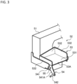
- FIG. 3 is a view for describing the discharge mechanism 52 of the creel robot 50.
- the discharge mechanism 52 includes a take-up tube receiving base 53 and a tilting mechanism 54, and is provided on the main body portion 51 of the creel robot 50.
- the take-up tube receiving base 53 includes a rectangular loading plate 531, and side surface plates 532 provided on three sides of the loading plate 531 so as to be substantially perpendicular to the loading plate 531, and is configured so that an upper portion thereof is open.
- a side surface portion on one side of the loading plate 531 without the provided side surface plates 532 is open, and this open side surface portion is referred to as a discharge port 53A.
- the tilting mechanism 54 is provided on the main body portion 51.
- the tilting mechanism 54 supports the take-up tube receiving base 53 in a tiltable manner so as to rotate between a posture in which the loading plate 531 is along substantially the horizontal direction (hereinafter referred to as a take-in posture) and a posture in which the loading plate 531 is tilted from the horizontal direction (hereinafter referred to as a discharge posture).
- the discharge port 53A of the take-up tube receiving base 53 supported in this way is configured to face substantially horizontally in the take-in posture so that no empty take-up tube accommodated in the take-up tube receiving base 53 is discharged from the discharge port 53A, and to face a diagonally downward in the discharge posture so that the empty take-up tube accommodated in the take-up tube receiving base 53 is discharged from the discharge port 53A.
- the tilting mechanism 54 includes a receiving base support mechanism 541 and a first engagement member 542.
- the receiving base support mechanism 541 supports the take-up tube receiving base 53 from below.
- the receiving base support mechanism 541 is rotatable with respect to the main body portion 51 together with the take-up tube receiving base 53 around a rotational shaft 55 provided below the discharge port 53A.
- the take-up tube receiving base 53 is capable of rotating between the take-in posture and the discharge posture.
- the receiving base support mechanism 541 includes an arm 541A extending in a direction away from the discharge port 53A.
- the first engagement member 542 is provided at a tip portion of this arm 541A.
- the first engagement member 542 has a cylindrical shape extending along a direction that is orthogonal to a longitudinal direction of the arm 541A and is horizontal.
- the receiving base support mechanism 541 rotates around the rotational shaft 55 so that the discharge port 53A faces downward as the first engagement member 542 is pressed downward by the take-up tube collection apparatus 21 (more specifically, a second engagement member 223C illustrated in FIG. 5 described below and the like).
- the take-up tube receiving base 53 supported by the receiving base support mechanism 541 also rotates.
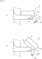
- FIG. 4 is a view for explaining a tilt of the take-up tube receiving base 53 by the tilting mechanism 54, which illustrates: (A) a state where the take-up tube receiving base 53 is in the take-in posture; and (B) a state where the take-up tube receiving base 53 is in the discharge posture.
- the creel robot 50 accommodates the empty take-up tube removed from the creel stand 30 to take-up tube receiving base 53 from the opened upper portion, when the take-up tube receiving base 53 is in a state of the take-in posture, and moves to the take-up tube collection apparatus 21 in the state of the take-in posture.
- the take-up tube collection apparatus 21 includes a rotating second engagement member 223C.
- the take-up tube receiving base 53 When the pressing force on the first engagement member 542 is removed, the take-up tube receiving base 53 returns from the discharge posture to the take-in posture.
- the rotational shaft 55 is provided on the discharge port 53A side of the take-up tube receiving base 53.
- the take-up tube collection apparatus 21 includes a guide device 22 and a collection box 23 (refer to FIGs. 1 and 2 ).
- FIG. 5 is a view illustrating a configuration of the guide device 22, which illustrates: (A) a standby posture; and (B) a collection posture.
- the standby posture is a posture when the take-up tube collection apparatus 21 is not collecting empty take-up tubes.
- the collection posture is a posture when the take-up tube collection apparatus 21 is collecting the empty take-up tubes.
- the guide device 22 rolls the empty take-up tube discharged from the take-up tube receiving base 53 at a predetermined height to be guided to the collection box 23.
- the guide device 22 includes a stand 221, a guide unit 222, and a guide unit drive mechanism 223.
- the stand 221 extends along the vertical direction and supports each component provided in the guide device 22.
- the stand 221 has a height that allows the guide unit 222 provided at an upper end portion thereof can be connected to the discharge mechanism 52 of the creel robot 50.
- the guide unit 222 is provided at the upper end portion of the stand 221.
- the guide unit 222 rolls the empty take-up tube discharged from the take-up tube receiving base 53, to be guided to the collection box 23. Since the take-up tube receiving base 53 is positioned at the predetermined height, the empty take-up tube discharged from the take-up tube receiving base 53 falls from the predetermined height. By rolling the empty take-up tube on the guide unit 222, the falling velocity thereof is suppressed rather than a case of free fall. Consequently, since the impact subjected to the empty take-up tube when being collected in the collection box 23 is reduced, it is possible to reduce the risk of the empty take-up tube being deformed or damaged.
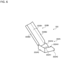
- FIG. 6 is a view illustrating a configuration of the guide unit 222.
- the guide unit 222 includes a first chute 222A and a second chute 222B.
- the first chute 222A includes a rectangular bottom plate 222A1, and the side surface plates 222A2 provided on three sides of the rectangular bottom plate so as to be substantially perpendicular to the bottom plate 222A1, and is configured so that an upper portion thereof is open.
- a side surface portion on one side of the bottom plate 222A1 without the provided side surface plates 222A2 is open, and this open portion is referred to as a discharge port 222A3.
- the first chute 222A is supported in a posture tilted from the horizontal direction in which the discharge port 222A3 faces diagonally downward so that the empty take-up tube received from the second chute 222B does not stop.
- the guide device 22 is disposed so that the discharge port 222A3 of the first chute 222A is positioned approximately directly above the collection box 23.
- the second chute 222B includes a rectangular bottom plate 222B1, and side surface plates 222B2 provided respectively on long sides of the rectangular bottom plate 222B1 so as to be substantially perpendicular to the bottom plate 222B1, and is configured so that an upper portion thereof is open.
- the second chute 222B is tilted so that the one open side surface portion (hereinafter referred to as an inlet port) is positioned above the other side surface portion (hereinafter referred to as a discharge port), and is supported so that the discharge port is positioned directly above the first chute 222A.
- the empty take-up tube discharged from the take-up tube receiving base 53 is taken into the second chute 222B from the inlet port of the second chute 222B, rolls on the bottom plate 222B1, and is discharged from the discharge port of the second chute 222B to the first chute 222A.
- the tilt angle of the second chute 222B is changed between the standby posture and the collection posture by a guide unit drive mechanism 223 described below.
- the bottom plate 222B1 corresponds to a "guide plate" used in the present invention.
- the guide unit drive mechanism 223 supports a guide unit 222 so as to be tiltable.
- the guide unit drive mechanism 223 includes a tilting member 223A extending in the vertical direction in the standby posture.
- the tilting member 223A has a lower end portion provided on the stand 221, and can be tilted at the lower end portion as a fulcrum. In the collection posture, the longitudinal direction of the tilting member 223A is tilted with respect to the vertical direction.
- the tilting member 223A supports the second chute 222B of the guide unit 222 by the guide unit support mechanism 223B on an upper end portion side thereof.
- the guide unit support mechanism 223B includes a link mechanism, and enables the second chute 222B to be tilted in accordance with a tilt of the tilting member 223A.
- the guide unit support mechanism 223B supports the second chute 222B so that, in the collection posture, the tilt angle corresponding to the longitudinal direction of the second chute 222B with respect to the vertical direction is greater than the that in the standby posture.
- the tilting member 223A corresponds to a "follower" used in the present invention.
- the second engagement member 223C is provided at an upper end portion of the tilting member 223A.
- the second engagement member 223C presses the first engagement member 542 while sliding against the first engagement member 542 (refer to FIG. 4 ) of the creel robot 50 (hereinafter referred to as a sliding engagement).
- the take-up tube receiving base 53 of the creel robot 50 which has already moved to the collection position is in the take-in posture, and the guide device 22 of the take-up tube collection apparatus 21 is in the standby posture.
- the guide device 22 drives the guide unit drive mechanism 223 to be shifted to the collection posture.
- the first engagement member 542 of the take-up tube receiving base 53 is positioned on a trajectory of the second engagement member 223C of the guide unit drive mechanism 223, and is pressed by the rotating second engagement member 223C. Consequently, the take-up tube receiving base 53 is tilted.
- the loading plate 531 of the take-up tube receiving base 53 and the bottom plate 222B1 of the second chute 222B are aligned in a substantially straight line.
- An angle formed between the loading plate 531 and the bottom plate 222B1 in this case is within a range of "180 degrees ⁇ the predetermined angle".
- the empty take-up tube accommodated in the take-up tube receiving base 53 rolls through the second chute 222B from the take-up tube receiving base 53 to the first chute 222A, and is collected in the collection box 23 (refer to FIG. 2 and the like) disposed below the discharge port of the first chute 222A.
- the rolling velocity of the empty take-up tube is more reduced compared with a case of being discharged directly from the take-up tube receiving base 53 without through the guide unit 222, and an impact when being collected by the collection box 23 can be reduced.
- the rolling velocity of the empty take-up tube is further reduced, and the impact when being collected by the collection box 23 can be further reduced.
- the predetermined angle in which an angle formed between the loading plate 531 and the bottom plate 222B1 is within the "a range of 180 degrees ⁇ predetermined angle” is preferable to be within a range of 20 to 60 degrees.
- the angle formed between the loading plate 531 and the bottom plate 222B1 is preferable to be within a range between a lower limit angle obtained by subtracting the predetermined angle from 180 degrees and an upper limit angle obtained by adding the predetermined angle to 180 degrees.
- the predetermined angle includes 0 degrees, i.e., the angle formed between the guide plate and the take-up tube receiving base includes "180 ⁇ 0 degrees".
- the predetermined angle is preferable to be within a range of 20 degrees to 60 degrees.
- the lower limit angle formed between the guide plate and the take-up tube receiving base is preferable to be 120 degrees, and is more preferable to be 160 degrees.
- the upper limit angle formed between the guide plate and the take-up tube receiving base is preferable to be 240 degrees, and more preferable to be 200 degrees.
- the tilt angle of the bottom plate 222B1 of the second chute 222B is smaller than the tilt angle of the loading plate 531 of the take-up tube receiving base 53.
- the gradient of the bottom plate 222B1 is smaller than the gradient of the loading plate 531. Therefore, it means that when the angle formed between the loading plate 531 and the bottom plate 222B1 is 120 degrees, the gradient of the bottom plate 222B1 is the smallest, and when the angle formed therebetween is 160 degrees, the gradient of the bottom plate 222B1 is slightly smaller.
- the tilt angle of the bottom plate 222B1 of the second chute 222B is greater than the tilt angle of the loading plate 531 of the take-up tube receiving base 53.
- the gradient of the bottom plate 222B1 is greater than the gradient of the loading plate 531. Therefore, it means that when the angle formed between the loading plate 531 and the bottom plate 222B1 is 240 degrees, the gradient of the bottom plate 222B1 is the greatest, and when the angle formed therebetween is 200 degrees, the gradient of the bottom plate 222B1 is slightly greater.
- FIG. 8 is a view for explaining a configuration of the collection box 23.
- the collection box 23 is a box for collecting the empty take-up tubes discharged from the guide device 22.
- the collection box 23 includes a frame body 231 and a bottom member 232.
- the frame body 231 is formed of pipes constructed in a rectangular parallelepiped shape extending in the vertical direction, for example.
- at least four side surfaces of the frame body 231 are formed of a net made of string, rubber, or steel constructed in a mesh pattern, and the frame body 231 includes an opening 23A having an open upper surface.
- the first chute 222A of the guide device 22 is disposed directly above this opening 23A.
- the bottom member 232 is supported, in the frame body 231, so as to be movable in the vertical direction along a rail (not illustrated) provided along the vertical direction.
- the bottom member 232 is also formed of pipes constructed in a flat plate shape in the same manner as the frame body 231, and has a flat surface portion formed of a net.
- the bottom member 232 is supported so as to be suspended from an upper portion of the frame body 231 by elastic string-like supporting member 233 such as rubber.
- elastic string-like supporting member 233 such as rubber.
- the empty take-up tube can be received before a moving velocity of the empty take-up tube increases. Consequently, it is possible to prevent deformation of the empty take-up tube, and since the bottom member 232 lowers in accordance with the weight of the loaded empty take-up tube, the maximum capacity of accommodation corresponding to a volume of the collection box 23 is not reduced significantly.
- the second engagement member 223C of the tilting member 223A is slidably engaged to the first engagement member 542, and thereby the take-up tube receiving base 53 supported by the receiving base support mechanism 541 is tilted. Consequently, the empty take-up tube accommodated in the take-up tube receiving base 53 moves from the take-up tube receiving base 53 to the first chute 222A and the second chute 222B, slides down the first chute 222A and the second chute 222B, and is fed into the collection box 23. Consequently, the take-up tube receiving base 53 of the creel robot 50 and the collection box 23 can be used in the already-existing configuration.
- the guide device 22 is configured so that when the guide device 22 is shifted to the collection posture, the take-up tube receiving base 53 is tilted, and the loading plate 531 and the bottom plate 222B1 are aligned in a substantially straight line.
- the guide device 22 approaches and connects to the creel robot 50 and thereby the loading plate 531 and the bottom plate 222B1 are aligned in the substantially straight line. Accordingly, by merely providing a new guide device 22 while using the conventional creel robot 50, it is possible to reduce the risk of deformation or damage to the empty take-up tube.
- the empty take-up tube is received by the bottom member 232 positioned higher than the bottom surface of the collection box 23 as comparing a case where the fed empty take-up tube is received and loaded on the bottom surface thereof, the empty take-up tube can be received before the falling velocity of the empty take-up tube increases. Consequently, it is possible to prevent deformation of the empty take-up tube, and since the bottom member 232 lowers in accordance with the weight of the loaded empty take-up tube, the maximum capacity of accommodation corresponding to a volume of the collection box 23 is not reduced significantly.
- the guide unit 222 of the guide device 22 includes the first chute 222A, but it may be not necessary to include such a first chute. Even in this case, since the empty take-up tube discharged from the take-up tube receiving base 53 rolls on the second chute 222B, it can suppress the falling velocity compared with the case of free fall.
- the take-up tube collection apparatus 21 tilts the take-up tube receiving base 53, but it is not limited to this example.
- the creel robot 50 may include a mechanism for tilting the take-up tube receiving base 53 independently of the take-up tube collection apparatus 21.
- the take-up tube receiving base 53 of the creel robot 50 and the second chute 222B of the guide device 22 may each be tilted and then approach each other.
- the take-up tube receiving base 53 may be configured to be manually tilted.
- the mechanism for returning the take-up tube receiving base 53 from the discharge posture to the take-in posture may be, for example, a mechanism for returning the take-up tube receiving base 53 to the take-in posture by utilizing an elastic member such as a spring.
- the discharge mechanism 52 of the creel robot 50 may be provided movably up and down with respect to the main body portion 51.
- the guide device 22 may also be configured to be movably up and down. In this case, even after installing the guide device 22, it is possible to adjust position alignment between the take-up tube receiving base 53 and the guide unit 222.
- the guide device 22 or the collection box 23 may be configured to be movable from their respective installation positions using casters or the like, or may be installed so as not to be movable.
- the "take-in posture” is defined as the posture of the loading plate 531 aligned substantially horizontally, but it is not limited to this example.
- the loading plate 531 may be tilted so that the discharge port 53A faces upward.
- the take-in posture may be any posture in which the empty take-up tube accommodated in the take-up tube receiving base 53 does not fall.
- the loading plate 531 of the take-up tube receiving base 53 and the bottom plate 222B1 of the second chute 222B are aligned in a substantially straight line, and at this time, it is preferable that the loading plate 531 and the bottom plate 222B1 are in close contact with each other without any gaps.
- the take-up tube collection system 1A is formed of the take-up tube collection apparatus 21 and the creel robot 50, but it is not limited to this example.
- the take-up tube collection system may be formed of the take-up tube collection apparatus 21, the creel robot 50, and the creel stands 30, 30A.
- the creel stands 30, 30A are arranged on both sides sandwiching the rail 20, and the yarn feeding packages are supplied to the creel stand 30 and the creel stand 30A by the creel robot 50 which moves on the rail 20, but it is not limited to this example.
- the creel robot 50 may supply the yarn feeding package to the creel stand (30 or 30A) arranged on any one side of the both sides sandwiching the rail 20.
- the four sides of the collection box 23 are formed of a net, but may be formed of a rigid plate member and covered with an elastic member such as a sponge. Moreover, the collection box 23 may not include the bottom member 232, and the net may be supported in a bag shape by the frame body 231 to collect the empty take-up tube.
Landscapes
- Replacing, Conveying, And Pick-Finding For Filamentary Materials (AREA)
Abstract
Description
- The present invention relates to a take-up tube collection system and a take-up tube collection apparatus.
- Regarding a technology of a take-up tube collection system and a take-up tube collection apparatus, configured to collect a take-up tube of a yarn feeding package, Patent document 1 discloses a technology in which a tilting table that engages a roller of a roller lever is provided at a predetermined height by a stand near the collection box of a take-up tube, and on the way to come down so that a yarn-feeding changer receives the yarn feeding package, the take-up tube is fed into the collection box from the predetermined height position by rotating the roller lever clockwise and tilting forward a take-up tube receiving base on which a take-up tube is loaded.
- Patent Document 1:
Japanese Patent Application Publication No. H06-056349 - Incidentally, in the above-described prior art, when the take-up tube feeding into the collection box from the predetermined height position, the take-up tube collides with the collection box at a high velocity, a large impact is subjected to the take-up tube fed into the collection box, and there is a risk that the take-up tube may be deformed or damaged. Since the take-up tube fed into the collection box may be reused, there is room for an improvement regarding such a collection of the take-up tube.
- The present invention has been made in view of the above-described technical problems, and an object thereof is to provide a take-up tube collection system and a take-up tube collection apparatus, capable of reducing an impact subjected to the take-up tube when being fed into the collection box and reducing a risk that the take-up tube may be deformed or damaged.
- A first aspect of the present invention is a take-up tube collection system comprising:
- a creel robot configured to supply a yarn feeding package in which a yarn is wound around a take-up tube and to collect an empty take-up tube after the yarn is unwound; and
- a take-up tube collection apparatus configured to collect the empty take-up tube discharged from the creel robot, wherein
- the creel robot includes:
- a take-up tube receiving base configured to be capable of accommodating the empty take-up tube and including a loading plate loading the empty take-up tube thereon and a discharge port capable of discharging the empty take-up tube; and
- a tilting mechanism configured to tilt the take-up tube receiving base so that the empty take-up tube discharged from the take-up tube receiving base is discharged from a predetermined height position at a collection position where the empty take-up tube can be collected in the take-up tube collection apparatus, wherein
- the take-up tube collection apparatus includes:
- a collection box configured to collect the empty take-up tube discharged from the take-up tube receiving base; and
- a guide device configured to guide the empty take-up tube discharged from the take-up tube receiving base to the collection box, wherein
- the guide device includes:
- a guide unit including a guide plate configured to roll the empty take-up tube discharged from the take-up tube receiving base to be guided to the collection box; and
- a guide unit drive mechanism configured to tilt the guide unit to approach the take-up tube receiving base so that an angle formed between the guide plate and the loading plate of the take-up tube receiving base tilted at the collection position is within a range of 180 degrees plus or minus (±) a predetermined angle.
- According to the above-described first aspect of the take-up tube collection system, the empty take-up tube discharged from the take-up tube receiving base is slowed down by friction with the guide plate when being guided by the guide plate and collected in the collection box. Therefore, a moving velocity when the empty take-up tube rolls on the guide plate is smaller than a falling velocity when the empty take-up tube is directly discharged from directly above the collection box. Consequently, since the impact subjected to the empty take-up tube when being collected in the collection box is reduced, it is possible to reduce the risk of the empty take-up tube being deformed or damaged.
- Herein, the predetermined angle in which the angle formed between the guide plate and the loading plate of the take-up tube receiving base tilted at the collection position is within the "a range of 180 degrees ± a predetermined angle" is preferable to be within a range of 20 to 60 degrees. Namely, the angle formed between the guide plate and the loading plate is preferable to be within a range between a lower limit angle obtained by subtracting the predetermined angle from 180 degrees and an upper limit angle obtained by adding the predetermined angle to 180 degrees. Accordingly, the predetermined angle includes 0 degrees, i.e., the angle formed between the guide plate and the loading plate includes "180±0 degrees". Furthermore, the predetermined angle is preferable to be within a range of 20 degrees to 60 degrees. Specifically, the lower limit angle formed between the guide plate and the take-up tube receiving base is preferable to be 120 degrees, and is more preferable to be 160 degrees. In contrast, the upper limit angle formed between the guide plate and the take-up tube receiving base is preferable to be 240 degrees, and more preferable to be 200 degrees.
- In detail, when the angle formed between the guide plate and the loading plate is 180 degrees, it is in a state where the loading plate and the guide plate are aligned in a straight line at the same tilt angle with respect to a vertical direction. Namely, the guide plate and the loading plate in this case have the same gradient.
- When the predetermined angle is an angle smaller than 180 degrees, i.e., is "180 degrees - the predetermined angle", the tilt angle of the guide plate is smaller than the tilt angle of the loading plate. This means that the gradient of the guide plate is smallerthan the gradient of the loading plate. Therefore, it means that when the angle formed between the guide plate and the loading plate is 120 degrees, the gradient of the guide plate is the smallest, and when the angle formed therebetween is 160 degrees, the gradient of the guide plate is slightly smaller.
- On the other hand, when the predetermined angle is an angle greater than 180 degrees, i.e., is "180 degrees + the predetermined angle", the tilt angle of the guide plate is larger than the tilt angle of the loading plate of the take-up tube receiving base. This means that the gradient of the guide plate is greater than the gradient of the loading plate. Therefore, it means that when the angle formed between the guide plate and the loading plate is 240 degrees, the gradient of the guide plate is the greatest, and when the angle formed therebetween is 200 degrees, the gradient of the guide plate is slightly greater.
- It is to be noted that the predetermined angle in which the angle formed between the guide plate and the loading plate is within the range of "180 degrees ± the predetermined angle" requires that the tilt angle (gradient) of the loading plate is to be a range from an angle corresponding to the vertical direction to an angle corresponding to the horizontal direction. This is because the empty take-up tube cannot be slowed down by the frictional force of the loading plate when the tilt angle (gradient) of the loading plate is an angle corresponding to the vertical direction. This is also because there is a high possibility that the empty take-up tube will be stopped by the loading plate when the tilt angle (gradient) of the loading plate is an angle corresponding to the horizontal direction.
- A second aspect of the present invention is the take-up tube collection system in the above-described first aspect, wherein preferably
the tilting mechanism includes: - a receiving base support mechanism configured to support the take-up tube receiving base so as to be tiltable; and
- a first engagement member provided in the receiving base support mechanism and configured to tilt the take-up tube receiving base, wherein
- the guide unit drive mechanism includes:
- a guide unit support mechanism configured to support the guide unit so as to be tiltable by a link mechanism; and
- a second engagement member provided at a tip portion of a follower of the link mechanism, and slidably engaged with the first engagement member by a rotation of the tip portion of the follower when the guide unit is tilted.
- According to the above-described second aspect of the take-up tube collection system, when the guide unit is tilted, the second engagement member is slidably engaged with the first engagement member of the tilting mechanism, and thereby the take-up tube receiving base supported by the receiving base support mechanism is tilted. Consequently, the empty take-up tube held on the take-up tube receiving base moves from the take-up tube receiving base to the guide unit, slides down the guide plate of the guide unit, and is fed into the collection box. Consequently, the take-up tube receiving base of the creel robot and the collection box can be used in the already-existing configuration.
- A third aspect of the present invention is the take-up tube collection system in the above-described first or second aspect, wherein preferably
the collection box includes: - a frame body capable of accommodating a plurality of the empty take-up tubes and having an opening formed on an upper surface thereof for collecting the empty take-up tubes;
- a bottom member loosely fitted in the frame body and on which the empty take-up tube collected from the opening is loaded; and
- a bottom member up-and-down mechanism configured to support the bottom member movably up and down so that when the empty take-up tube is not loaded on the bottom member, the bottom member is raised to an initial height position and the bottom member is lowered in accordance with a weight of the empty take-up tube loaded on the bottom member.
- According to the above-described third aspect of the take-up tube collection system, since the empty take-up tube is received by the bottom member positioned higher than a bottom surface of the collection box as comparing a case where the fed empty take-up tube is received and loaded on the bottom surface thereof, the empty take-up tube can be received before a falling velocity of the empty take-up tube increases. Consequently, it is possible to prevent deformation of the empty take-up tube, and since the bottom member lowers in accordance with the weight of the loaded empty take-up tube, the maximum capacity of accommodation corresponding to a volume of the frame body is not reduced significantly.
- A fourth aspect of the present invention is the take-up tube collection system in the above-described any one of first to third aspects, preferably further comprising
a creel stand arranged along a travel passage of the creel robot, in which the creel robot is configured to supply the yarn feeding package and to collect the empty take-up tube. - According to the above-described fourth aspect of the take-up tube collection system, even when a large amount of empty take-up tubes are collected from the creel stand, deformation of the empty take-up tube can be sufficiently prevented.
- A fifth aspect of the present invention is
- a take-up tube collection apparatus configured to collect an empty take-up tube discharged from a predetermined height position by a creel robot, the creel robot including: a take-up tube receiving base configured to be capable of accommodating the empty take-up tube after a yarn is unwound and including a loading plate loading the empty take-up tube thereon and a discharge port capable of discharging the empty take-up tube; and a tilting mechanism configured tilt the take-up tube receiving base so that the empty take-up tube is discharged from the predetermined height position at a collection position where the empty take-up tube is collected,
- the take-up tube collection apparatus comprising:
- a collection box configured to collect the empty take-up tube discharged from the take-up tube receiving base; and
- a guide device configured to guide the empty take-up tube discharged from the take-up tube receiving base to the collection box, wherein
- the guide device includes:
- a guide unit including a guide plate configured to roll the empty take-up tube discharged from the take-up tube receiving base to be guided to the collection box; and
- a guide unit drive mechanism configured to tilt the guide unit to approach the take-up tube receiving base so that an angle formed between the guide plate and the loading plate of the take-up tube receiving base tilted at the collection position is within a range of 180 degrees plus or minus (±) a predetermined angle.
- According to the above-described fifth aspect of the take-up tube collection apparatus, the empty take-up tube is slowed down by friction with the guide plate when being guided by the guide plate and collected in the collection box. Therefore, the moving velocity of the empty take-up tube is slower than that of in a case of being directly discharged from directly above the collection box. Consequently, since the impact subjected to the empty take-up tube when being collected in the collection box is reduced, it is possible to reduce the risk of the empty take-up tube being deformed or damaged.
- A sixth aspect of the present invention is the take-up tube collection apparatus in the above-described fifth aspect, wherein preferably
- the tilting mechanism includes:
- a receiving base support mechanism configured to support the take-up tube receiving base so as to be tiltable; and
- a first engagement member provided in the receiving base support mechanism and configured to tilt the take-up tube receiving base, wherein
- the guide unit drive mechanism includes:
- a guide unit support mechanism configured to support the guide unit so as to be tiltable; and
- a second engagement member provided in the guide unit support mechanism and slidably engaged with the first engagement member due to the tilt of the guide unit.
- According to a take-up tube collection apparatus described in the above-described sixth aspect, when the guide unit is tilted, the second engagement member is slidably engaged with the first engagement member of the tilting mechanism, and thereby the take-up tube receiving base supported by the receiving base support mechanism is tilted. Consequently, the empty take-up tube held on the take-up tube receiving base moves from the take-up tube receiving base to the guide unit, slides down the guide plate of the guide unit, and is fed into the collection box. Consequently, the take-up tube receiving base of the creel robot and the collection box can be used in the already-existing configuration.
- A seventh aspect of the present invention is the take-up tube collection apparatus in the above-described fifth or sixth aspect, wherein preferably
the collection box includes: - a frame body capable of accommodating a plurality of the empty take-up tubes and having an opening formed on an upper surface thereof for collecting the empty take-up tubes;
- a bottom member loosely fitted in the frame body and on which the empty take-up tube collected from the opening is loaded; and
- a bottom member up-and-down mechanism configured to support the bottom member movably up and down so that when the empty take-up tube is not loaded on the bottom member, the bottom member is raised to an initial height position and the bottom member is lowered in accordance with a weight of the empty take-up tube loaded on the bottom member.
- According to a take-up tube collection apparatus described in the above-described seventh aspect, since the empty take-up tube is received by the bottom member positioned higher than a bottom surface of the collection box as comparing a case where the fed empty take-up tube is received and loaded on the bottom surface thereof, the empty take-up tube can be received before a moving velocity of the empty take-up tube increases. Consequently, it is possible to prevent deformation of the empty take-up tube, and since the bottom member lowers in accordance with the weight of the loaded empty take-up tube, the maximum capacity of accommodation corresponding to a volume of the frame body is not reduced significantly.
- The take-up tube collection system according to the present invention may be formed of merely the configuration described as the take-up tube collection system described in the above-described first aspect, or may be formed of freely combining the configuration described in the above-described first aspect with the configuration(s) described in any of the above-described second to fourth aspects, to the extent that consistency can be achieved. When combining the configuration described in the above-described first aspect with the configuration(s) described in any of the above-described second to fourth aspects, all or part of the configuration described in the above-described first aspect can be combined with all or part of configurations of described in the above-described second to fourth aspects, to the extent that consistency can be achieved. Moreover, the take-up tube collection apparatus according to the present invention may be formed of merely the configuration described as the take-up tube collection apparatus described in the above-described fifth aspect, or may be formed of freely combining the configuration described in the above-described fifth aspect with the configuration(s) described in any of the above-described sixth and seventh aspects, to the extent that consistency can be achieved. When combining the configuration described in the above-described fifth aspect with the configuration(s) described in any of the above-described sixth and seventh aspects, all or part of the configuration described in the above-described fifth aspect can be combined with all or part of configurations of described in the above-described sixth and seventh aspects, to the extent that consistency can be achieved.
- According to the present invention, it is possible to provide a take-up tube collection system and a take-up tube collection apparatus, capable of reducing an impact subjected to the take-up tube when being fed into the collection box and reducing a risk that the take-up tube may be deformed or damaged.
-
-
FIG. 1 is a plan view schematically illustrating an overall arrangement configuration example of a false-twist texturing system. -
FIG. 2 is an example of a perspective view schematically illustrating a take-up tube collection system. -
FIG. 3 is a view for describing a discharge mechanism of a creel robot. -
FIG. 4 is a view for explaining a tilt of a take-up tube receiving base by a tilting mechanism, which illustrates: (A) a state where the take-up tube receiving base is in a take-in posture; and (B) a state where the take-up tube receiving base is in a discharge posture. -
FIG. 5 is a view illustrating a configuration of a guide device, which illustrates: (A) a standby posture; and (B) a collection posture. -
FIG. 6 is a view illustrating a configuration of a guide unit. -
FIG. 7 is a view for explaining a sliding engagement between an engagement member of the guide unit drive mechanism and an engagement member of the creel robot. -
FIG. 8 is a view for explaining a configuration of a collection box. - Hereinafter, embodiments for carrying out the present invention will be described with reference to the drawings.
-
FIG. 1 is a plan view schematically illustrating an overall arrangement configuration example of a false-twist texturing system 1. In the false-twist texturing system 1, a yarn feeding package in which a yarn is wound around a cylindrical take-up tube is supplied to acreel stand 30 and acreel stand 30A by acreel robot 50 that moves on arail 20 extending in a linear shape. Moreover, an empty take-up tube, around which no yarn is wound (hereinafter referred to as an empty take-up tube), by thecreel robot 50 is collected from the creel stands 30, 30A. The "yarn" used herein is exemplified by synthetic fibers, such as polyester. The "yarn feeding package" is a winding-type package for supplying a yarn (synthetic fiber) used in a manufacturing process, such as a false-twist texturing machine. The yarn feeding package is composed of a take-up tube having a cylindrical shape of a center part, and the yarn wound around the take-up tube, and is held by inserting a peg of the creel stands 30, 30A inside the take-up tube. Therail 20 corresponds to a "travel passage" used in the present invention. - The creel stands 30, 30A are arranged at both sides sandwiching the
rail 20 and each extend along therail 20. A rawyarn storage unit 26 is provided at a position adjacent to the creel stand 30A in a longitudinal direction. The yarn feeding package is temporarily stored in the rawyarn storage unit 26 from a plant-wide conveyance device. The stored yarn feeding packages are taken out by thecreel robot 50 and are carried to the creel stands 30, 30A. - A
machine base 10 is provided at a position, which is adjacent to thecreel stand 30 and an opposite side to therail 20. Although not illustrated, a similar machine base is provided also at a position adjacent to the creel stand 30A. Themachine base 10 mainly includes, for example, a false-twist texturing machine 12 and a windingmachine 14. The yarn unwound from the yarn feeding package is supplied from the creel stand 30 to the false-twist texturing machine 12. In the false-twist texturing machine 12, the yarn unwound from the yarn feeding package is false-twisted. The false-twisted yarn is wound by the windingmachine 14. - After all yarn are unwound from the yarn feeding package, the empty take-up tube is collected by the
creel robot 50 from thecreel stand 30. The collected empty take-up tube is carried by thecreel robot 50 to the take-uptube collection apparatus 21 provided adjacent to the creel stand 30 in the longitudinal direction, and is discharged to the take-uptube collection apparatus 21. In the take-uptube collection apparatus 21, the empty take-up tube is collected by thecollection box 23 through theguide device 22. The take-uptube collection apparatus 21 and thecreel robot 50 form a take-uptube collection system 1A. -
FIG. 2 is an example of a perspective view schematically illustrating a take-uptube collection system 1A. InFIG. 2 , acreel stand 30 is also illustrated in addition to the take-uptube collection apparatus 21 and thecreel robot 50 forming the take-uptube collection system 1A. - The creel stand 30 is configured so that a plurality of column supports 31 extending in a vertical direction and arranged in two rows along the
rail 20 are provided therein, and a plurality ofpartition plates 32 are supported by the column supports 31 at a predetermined distance. A peg (not illustrated) that supports the take-up tube is provided in thecolumn support 31 near therail 20 among the plurality of column supports 31. - The
creel robot 50 includes amain body portion 51 and adischarge mechanism 52. Moreover, thecreel robot 50 includes a mechanism (not illustrated) capable of moving up and down with respect to themain body portion 51 and removing the empty take-up tube from the peg of thecreel stand 30. Thecreel robot 50 conveys the empty take-up tube removed from the creel stand 30 by the mechanism to the take-uptube collection apparatus 21. Thecreel robot 50 conveys the empty take-up tube to the take-uptube collection apparatus 21 and then discharge the empty take-up tube to the take-uptube collection apparatus 21 by thedischarge mechanism 52. -
FIG. 3 is a view for describing thedischarge mechanism 52 of thecreel robot 50. Thedischarge mechanism 52 includes a take-uptube receiving base 53 and atilting mechanism 54, and is provided on themain body portion 51 of thecreel robot 50. - The take-up
tube receiving base 53 includes arectangular loading plate 531, andside surface plates 532 provided on three sides of theloading plate 531 so as to be substantially perpendicular to theloading plate 531, and is configured so that an upper portion thereof is open. A side surface portion on one side of theloading plate 531 without the providedside surface plates 532 is open, and this open side surface portion is referred to as adischarge port 53A. - The
tilting mechanism 54 is provided on themain body portion 51. Thetilting mechanism 54 supports the take-uptube receiving base 53 in a tiltable manner so as to rotate between a posture in which theloading plate 531 is along substantially the horizontal direction (hereinafter referred to as a take-in posture) and a posture in which theloading plate 531 is tilted from the horizontal direction (hereinafter referred to as a discharge posture). Thedischarge port 53A of the take-uptube receiving base 53 supported in this way is configured to face substantially horizontally in the take-in posture so that no empty take-up tube accommodated in the take-uptube receiving base 53 is discharged from thedischarge port 53A, and to face a diagonally downward in the discharge posture so that the empty take-up tube accommodated in the take-uptube receiving base 53 is discharged from thedischarge port 53A. - The
tilting mechanism 54 includes a receivingbase support mechanism 541 and afirst engagement member 542. The receivingbase support mechanism 541 supports the take-uptube receiving base 53 from below. Moreover, the receivingbase support mechanism 541 is rotatable with respect to themain body portion 51 together with the take-uptube receiving base 53 around arotational shaft 55 provided below thedischarge port 53A. In accordance with this configuration, the take-uptube receiving base 53 is capable of rotating between the take-in posture and the discharge posture. - Moreover, the receiving
base support mechanism 541 includes anarm 541A extending in a direction away from thedischarge port 53A. Thefirst engagement member 542 is provided at a tip portion of thisarm 541A. Thefirst engagement member 542 has a cylindrical shape extending along a direction that is orthogonal to a longitudinal direction of thearm 541A and is horizontal. The receivingbase support mechanism 541 rotates around therotational shaft 55 so that thedischarge port 53A faces downward as thefirst engagement member 542 is pressed downward by the take-up tube collection apparatus 21 (more specifically, asecond engagement member 223C illustrated inFIG. 5 described below and the like). Moreover, the take-uptube receiving base 53 supported by the receivingbase support mechanism 541 also rotates. -
FIG. 4 is a view for explaining a tilt of the take-uptube receiving base 53 by thetilting mechanism 54, which illustrates: (A) a state where the take-uptube receiving base 53 is in the take-in posture; and (B) a state where the take-uptube receiving base 53 is in the discharge posture. - The
creel robot 50 accommodates the empty take-up tube removed from the creel stand 30 to take-uptube receiving base 53 from the opened upper portion, when the take-uptube receiving base 53 is in a state of the take-in posture, and moves to the take-uptube collection apparatus 21 in the state of the take-in posture. Although details will be described later, the take-uptube collection apparatus 21 includes a rotatingsecond engagement member 223C. When thecreel robot 50 is in a collection position, thefirst engagement member 542 of the take-uptube receiving base 53 is positioned on a rotational trajectory of thesecond engagement member 223C. Then, thefirst engagement member 542 is pressed, at the collection position thereof, in a direction indicated by the hollow arrow inFIG. 4 (A) by the rotatingsecond engagement member 223C. Consequently, the take-uptube receiving base 53 together with thetilting mechanism 54 tilts and the take-uptube receiving base 53 is in the discharge posture. When the take-uptube receiving base 53 becomes in the discharge posture, the empty take-up tube accommodated in the take-uptube receiving base 53 rolls due to gravity and is discharged from thedischarge port 53A to the take-uptube collection apparatus 21. - When the pressing force on the
first engagement member 542 is removed, the take-uptube receiving base 53 returns from the discharge posture to the take-in posture. Therotational shaft 55 is provided on thedischarge port 53A side of the take-uptube receiving base 53. When thefirst engagement member 542 is pressed, thetilting mechanism 54, which maintains the take-in posture, tilts so that thedischarge port 53A faces downward. Then, when the pressing force is removed, thetilting mechanism 54 returns to the take-in posture due to the weight of itself and the take-uptube receiving base 53. - The take-up
tube collection apparatus 21 includes aguide device 22 and a collection box 23 (refer toFIGs. 1 and2 ).FIG. 5 is a view illustrating a configuration of theguide device 22, which illustrates: (A) a standby posture; and (B) a collection posture. The standby posture is a posture when the take-uptube collection apparatus 21 is not collecting empty take-up tubes. The collection posture is a posture when the take-uptube collection apparatus 21 is collecting the empty take-up tubes. - At the collection position of the empty take-up tube in the take-up
tube collection apparatus 21, theguide device 22 rolls the empty take-up tube discharged from the take-uptube receiving base 53 at a predetermined height to be guided to thecollection box 23. Theguide device 22 includes astand 221, aguide unit 222, and a guideunit drive mechanism 223. - The
stand 221 extends along the vertical direction and supports each component provided in theguide device 22. Thestand 221 has a height that allows theguide unit 222 provided at an upper end portion thereof can be connected to thedischarge mechanism 52 of thecreel robot 50. - The
guide unit 222 is provided at the upper end portion of thestand 221. Theguide unit 222 rolls the empty take-up tube discharged from the take-uptube receiving base 53, to be guided to thecollection box 23. Since the take-uptube receiving base 53 is positioned at the predetermined height, the empty take-up tube discharged from the take-uptube receiving base 53 falls from the predetermined height. By rolling the empty take-up tube on theguide unit 222, the falling velocity thereof is suppressed rather than a case of free fall. Consequently, since the impact subjected to the empty take-up tube when being collected in thecollection box 23 is reduced, it is possible to reduce the risk of the empty take-up tube being deformed or damaged. -
FIG. 6 is a view illustrating a configuration of theguide unit 222. Theguide unit 222 includes afirst chute 222A and asecond chute 222B. - The
first chute 222A includes a rectangular bottom plate 222A1, and the side surface plates 222A2 provided on three sides of the rectangular bottom plate so as to be substantially perpendicular to the bottom plate 222A1, and is configured so that an upper portion thereof is open. A side surface portion on one side of the bottom plate 222A1 without the provided side surface plates 222A2 is open, and this open portion is referred to as a discharge port 222A3. Thefirst chute 222A is supported in a posture tilted from the horizontal direction in which the discharge port 222A3 faces diagonally downward so that the empty take-up tube received from thesecond chute 222B does not stop. Theguide device 22 is disposed so that the discharge port 222A3 of thefirst chute 222A is positioned approximately directly above thecollection box 23. - The
second chute 222B includes a rectangular bottom plate 222B1, and side surface plates 222B2 provided respectively on long sides of the rectangular bottom plate 222B1 so as to be substantially perpendicular to the bottom plate 222B1, and is configured so that an upper portion thereof is open. Thesecond chute 222B is tilted so that the one open side surface portion (hereinafter referred to as an inlet port) is positioned above the other side surface portion (hereinafter referred to as a discharge port), and is supported so that the discharge port is positioned directly above thefirst chute 222A. The empty take-up tube discharged from the take-uptube receiving base 53 is taken into thesecond chute 222B from the inlet port of thesecond chute 222B, rolls on the bottom plate 222B1, and is discharged from the discharge port of thesecond chute 222B to thefirst chute 222A. The tilt angle of thesecond chute 222B is changed between the standby posture and the collection posture by a guideunit drive mechanism 223 described below. The bottom plate 222B1 corresponds to a "guide plate" used in the present invention. - Return to
FIG. 5 . The guideunit drive mechanism 223 supports aguide unit 222 so as to be tiltable. The guideunit drive mechanism 223 includes a tiltingmember 223A extending in the vertical direction in the standby posture. The tiltingmember 223A has a lower end portion provided on thestand 221, and can be tilted at the lower end portion as a fulcrum. In the collection posture, the longitudinal direction of the tiltingmember 223A is tilted with respect to the vertical direction. - The tilting
member 223A supports thesecond chute 222B of theguide unit 222 by the guideunit support mechanism 223B on an upper end portion side thereof. The guideunit support mechanism 223B includes a link mechanism, and enables thesecond chute 222B to be tilted in accordance with a tilt of the tiltingmember 223A. Moreover, the guideunit support mechanism 223B supports thesecond chute 222B so that, in the collection posture, the tilt angle corresponding to the longitudinal direction of thesecond chute 222B with respect to the vertical direction is greater than the that in the standby posture. The tiltingmember 223A corresponds to a "follower" used in the present invention. - The
second engagement member 223C is provided at an upper end portion of the tiltingmember 223A. When theguide device 22 is shifted from the standby posture to the collection posture, thesecond engagement member 223C presses thefirst engagement member 542 while sliding against the first engagement member 542 (refer toFIG. 4 ) of the creel robot 50 (hereinafter referred to as a sliding engagement). -
FIG. 7 is a view for explaining a sliding engagement between thesecond engagement member 223C of the guideunit drive mechanism 223 and thefirst engagement member 542 of thecreel robot 50. - The take-up
tube receiving base 53 of thecreel robot 50 which has already moved to the collection position is in the take-in posture, and theguide device 22 of the take-uptube collection apparatus 21 is in the standby posture. In this state, theguide device 22 drives the guideunit drive mechanism 223 to be shifted to the collection posture. Thefirst engagement member 542 of the take-uptube receiving base 53 is positioned on a trajectory of thesecond engagement member 223C of the guideunit drive mechanism 223, and is pressed by the rotatingsecond engagement member 223C. Consequently, the take-uptube receiving base 53 is tilted. As a result, theloading plate 531 of the take-uptube receiving base 53 and the bottom plate 222B1 of thesecond chute 222B are aligned in a substantially straight line. An angle formed between theloading plate 531 and the bottom plate 222B1 in this case is within a range of "180 degrees ± the predetermined angle". - Consequently, the empty take-up tube accommodated in the take-up
tube receiving base 53 rolls through thesecond chute 222B from the take-uptube receiving base 53 to thefirst chute 222A, and is collected in the collection box 23 (refer toFIG. 2 and the like) disposed below the discharge port of thefirst chute 222A. Thus, by configuring so that the empty take-up tube discharged from the take-uptube receiving base 53 is collected in thecollection box 23 through theguide unit 222, the rolling velocity of the empty take-up tube is more reduced compared with a case of being discharged directly from the take-uptube receiving base 53 without through theguide unit 222, and an impact when being collected by thecollection box 23 can be reduced. Furthermore, by changing the rolling direction of the empty take-up tube by thefirst chute 222A, the rolling velocity of the empty take-up tube is further reduced, and the impact when being collected by thecollection box 23 can be further reduced. - Herein, the predetermined angle in which an angle formed between the
loading plate 531 and the bottom plate 222B1 is within the "a range of 180 degrees ± predetermined angle" is preferable to be within a range of 20 to 60 degrees. Namely, the angle formed between theloading plate 531 and the bottom plate 222B1 is preferable to be within a range between a lower limit angle obtained by subtracting the predetermined angle from 180 degrees and an upper limit angle obtained by adding the predetermined angle to 180 degrees. Accordingly, the predetermined angle includes 0 degrees, i.e., the angle formed between the guide plate and the take-up tube receiving base includes "180±0 degrees". Furthermore, the predetermined angle is preferable to be within a range of 20 degrees to 60 degrees. Specifically, the lower limit angle formed between the guide plate and the take-up tube receiving base is preferable to be 120 degrees, and is more preferable to be 160 degrees. In contrast, the upper limit angle formed between the guide plate and the take-up tube receiving base is preferable to be 240 degrees, and more preferable to be 200 degrees. - When the predetermined angle is an angle smaller than 180 degrees, i.e., is "180 degrees - the predetermined angle", the tilt angle of the bottom plate 222B1 of the
second chute 222B is smaller than the tilt angle of theloading plate 531 of the take-uptube receiving base 53. This means that the gradient of the bottom plate 222B1 is smaller than the gradient of theloading plate 531. Therefore, it means that when the angle formed between theloading plate 531 and the bottom plate 222B1 is 120 degrees, the gradient of the bottom plate 222B1 is the smallest, and when the angle formed therebetween is 160 degrees, the gradient of the bottom plate 222B1 is slightly smaller. - On the other hand, when the predetermined angle is an angle greater than 180 degrees, i.e., is "180 degrees + the predetermined angle", the tilt angle of the bottom plate 222B1 of the
second chute 222B is greater than the tilt angle of theloading plate 531 of the take-uptube receiving base 53. This means that the gradient of the bottom plate 222B1 is greater than the gradient of theloading plate 531. Therefore, it means that when the angle formed between theloading plate 531 and the bottom plate 222B1 is 240 degrees, the gradient of the bottom plate 222B1 is the greatest, and when the angle formed therebetween is 200 degrees, the gradient of the bottom plate 222B1 is slightly greater. -
FIG. 8 is a view for explaining a configuration of thecollection box 23. - The
collection box 23 is a box for collecting the empty take-up tubes discharged from theguide device 22. Thecollection box 23 includes aframe body 231 and abottom member 232. Theframe body 231 is formed of pipes constructed in a rectangular parallelepiped shape extending in the vertical direction, for example. Moreover, at least four side surfaces of theframe body 231 are formed of a net made of string, rubber, or steel constructed in a mesh pattern, and theframe body 231 includes anopening 23A having an open upper surface. Thefirst chute 222A of theguide device 22 is disposed directly above thisopening 23A. Thebottom member 232 is supported, in theframe body 231, so as to be movable in the vertical direction along a rail (not illustrated) provided along the vertical direction. Thebottom member 232 is also formed of pipes constructed in a flat plate shape in the same manner as theframe body 231, and has a flat surface portion formed of a net. By forming the side surfaces of theframe body 231 and the flat surface of thebottom member 232 of the net, an impact when the empty take-up tube is discharged into thecollection box 23 is relieved rather than a case of being formed of a rigid plate member. - The
bottom member 232 is supported so as to be suspended from an upper portion of theframe body 231 by elastic string-like supportingmember 233 such as rubber. When no empty take-up tube is loaded on thebottom member 232, the supportingmember 233, by its own elastic force, raises thebottom member 232 to an initial height position and lowers thebottom member 232 in accordance with the weight of the empty take-up tube loaded on thebottom member 232. The supportingmember 233 corresponds to a "bottom member up-and-down mechanism" used in the present invention. - By allowing the
bottom member 232 to be raised and lowered in accordance with the weight, since the empty take-up tube is received by thebottom member 232 positioned higher than the bottom surface of thecollection box 23 as comparing a case where the fed empty take-up tube is received and loaded on the bottom surface positioned below thecollection box 23, the empty take-up tube can be received before a moving velocity of the empty take-up tube increases. Consequently, it is possible to prevent deformation of the empty take-up tube, and since thebottom member 232 lowers in accordance with the weight of the loaded empty take-up tube, the maximum capacity of accommodation corresponding to a volume of thecollection box 23 is not reduced significantly. - As described above, when the empty take-up tube discharged from the take-up
tube receiving base 53 is guided to thefirst chute 222A and thesecond chute 222B of theguide device 22 and is collected in thecollection box 23, the empty take-up tube is slowed down due to the friction with thefirst chute 222A and thesecond chute 222B. Therefore, a moving velocity when the empty take-up tube rolls on thefirst chute 222A and thesecond chute 222B is smaller than a falling velocity when the empty take-up tube is directly discharged from directly above thecollection box 23. Consequently, since the impact subjected to the empty take-up tube when being collected in thecollection box 23 is reduced, it is possible to reduce the risk of the empty take-up tube being deformed or damaged. - Moreover, when the
second chute 222B is tilted, thesecond engagement member 223C of the tiltingmember 223A is slidably engaged to thefirst engagement member 542, and thereby the take-uptube receiving base 53 supported by the receivingbase support mechanism 541 is tilted. Consequently, the empty take-up tube accommodated in the take-uptube receiving base 53 moves from the take-uptube receiving base 53 to thefirst chute 222A and thesecond chute 222B, slides down thefirst chute 222A and thesecond chute 222B, and is fed into thecollection box 23. Consequently, the take-uptube receiving base 53 of thecreel robot 50 and thecollection box 23 can be used in the already-existing configuration. - Moreover, it is configured so that when the
guide device 22 is shifted to the collection posture, the take-uptube receiving base 53 is tilted, and theloading plate 531 and the bottom plate 222B1 are aligned in a substantially straight line. In other words, it is configured so that, instead of thecreel robot 50 approaching and connecting to theguide device 22, theguide device 22 approaches and connects to thecreel robot 50 and thereby theloading plate 531 and the bottom plate 222B1 are aligned in the substantially straight line. Accordingly, by merely providing anew guide device 22 while using theconventional creel robot 50, it is possible to reduce the risk of deformation or damage to the empty take-up tube. - Since the empty take-up tube is received by the
bottom member 232 positioned higher than the bottom surface of thecollection box 23 as comparing a case where the fed empty take-up tube is received and loaded on the bottom surface thereof, the empty take-up tube can be received before the falling velocity of the empty take-up tube increases. Consequently, it is possible to prevent deformation of the empty take-up tube, and since thebottom member 232 lowers in accordance with the weight of the loaded empty take-up tube, the maximum capacity of accommodation corresponding to a volume of thecollection box 23 is not reduced significantly. - While this embodiment of the present invention has been described above, the present invention is not limited to the above-described embodiment but can be changed in various ways within a scope recited in the claims. For example, in above-described embodiment, the
guide unit 222 of theguide device 22 includes thefirst chute 222A, but it may be not necessary to include such a first chute. Even in this case, since the empty take-up tube discharged from the take-uptube receiving base 53 rolls on thesecond chute 222B, it can suppress the falling velocity compared with the case of free fall. - Moreover, in the above-described embodiment, the take-up
tube collection apparatus 21 tilts the take-uptube receiving base 53, but it is not limited to this example. For example, thecreel robot 50 may include a mechanism for tilting the take-uptube receiving base 53 independently of the take-uptube collection apparatus 21. For example, the take-uptube receiving base 53 of thecreel robot 50 and thesecond chute 222B of theguide device 22 may each be tilted and then approach each other. Moreover, the take-uptube receiving base 53 may be configured to be manually tilted. Furthermore, the mechanism for returning the take-uptube receiving base 53 from the discharge posture to the take-in posture may be, for example, a mechanism for returning the take-uptube receiving base 53 to the take-in posture by utilizing an elastic member such as a spring. - Moreover, the
discharge mechanism 52 of thecreel robot 50 may be provided movably up and down with respect to themain body portion 51. Theguide device 22 may also be configured to be movably up and down. In this case, even after installing theguide device 22, it is possible to adjust position alignment between the take-uptube receiving base 53 and theguide unit 222. Moreover, theguide device 22 or thecollection box 23 may be configured to be movable from their respective installation positions using casters or the like, or may be installed so as not to be movable. - Moreover, in the above embodiment, the "take-in posture" is defined as the posture of the
loading plate 531 aligned substantially horizontally, but it is not limited to this example. For example, theloading plate 531 may be tilted so that thedischarge port 53A faces upward. Namely, the take-in posture may be any posture in which the empty take-up tube accommodated in the take-uptube receiving base 53 does not fall. - Moreover, when collecting empty take-up tubes, the
loading plate 531 of the take-uptube receiving base 53 and the bottom plate 222B1 of thesecond chute 222B are aligned in a substantially straight line, and at this time, it is preferable that theloading plate 531 and the bottom plate 222B1 are in close contact with each other without any gaps. However, it is not limited to this example, for example, as long as the empty take-up tube can roll to thefirst chute 222A without stopping, there may be a gap between theloading plate 531 and the bottom plate 222B1. - Moreover, in the above-described embodiment, the take-up
tube collection system 1A is formed of the take-uptube collection apparatus 21 and thecreel robot 50, but it is not limited to this example. For example, the take-up tube collection system may be formed of the take-uptube collection apparatus 21, thecreel robot 50, and the creel stands 30, 30A. - Moreover, in the above-described embodiment, the creel stands 30, 30A are arranged on both sides sandwiching the
rail 20, and the yarn feeding packages are supplied to thecreel stand 30 and the creel stand 30A by thecreel robot 50 which moves on therail 20, but it is not limited to this example. For example, thecreel robot 50 may supply the yarn feeding package to the creel stand (30 or 30A) arranged on any one side of the both sides sandwiching therail 20. - Furthermore, the four sides of the
collection box 23 are formed of a net, but may be formed of a rigid plate member and covered with an elastic member such as a sponge. Moreover, thecollection box 23 may not include thebottom member 232, and the net may be supported in a bag shape by theframe body 231 to collect the empty take-up tube. -
- 1A
- Take-up tube collection system
- 21
- Take-up tube collection apparatus
- 22
- Guide device
- 23
- Collection box
- 30 30A
- Creel stand
- 50
- Creel robot
- 51
- Main body portion
- 52
- Discharge mechanism
- 53
- Take-up tube receiving base
- 53A
- Discharge port
- 54
- Tilting mechanism
- 55
- Rotational shaft
- 221
- Stand
- 222
- Guide unit
- 222A
- First chute
- 222A1
- Bottom plate
- 222A2
- Side surface plate
- 222A3
- Discharge port
- 222B
- Second chute
- 222B1
- Bottom plate
- 223
- Guide unit drive mechanism
- 223A
- Tilting member
- 223B
- Guide unit support mechanism
- 223C
- Second engagement member
- 231
- Frame body
- 232
- Bottom member
- 233
- Supporting member
- 531
- Loading plate
- 532
- Side surface plate
- 541
- Receiving base support mechanism
- 542
- First engagement member
Claims (7)
- A take-up tube collection system (1A) comprising:a creel robot (50) configured to supply a yarn feeding package in which a yarn is wound around a take-up tube and to collect an empty take-up tube after the yarn is unwound; anda take-up tube collection apparatus (21) configured to collect the empty take-up tube discharged from the creel robot (50), whereinthe creel robot (50) includes:a take-up tube receiving base (53) configured to be capable of accommodating the empty take-up tube and including a loading plate (531) loading the empty take-up tube thereon and a discharge port (53A) capable of discharging the empty take-up tube; anda tilting mechanism (54) configured to tilt the take-up tube receiving base (53) so that the empty take-up tube discharged from the take-up tube receiving base (53) is discharged from a predetermined height position at a collection position where the empty take-up tube can be collected in the take-up tube collection apparatus (21), whereinthe take-up tube collection apparatus (21) includes:a collection box (23) configured to collect the empty take-up tube discharged from the take-up tube receiving base (53); anda guide device (22) configured to guide the empty take-up tube discharged from the take-up tube receiving base (53) to the collection box (23), whereinthe guide device (22) includes:a guide unit (222) including a guide plate (bottom plate 222B1) configured to roll the empty take-up tube discharged from the take-up tube receiving base (53) to be guided to the collection box (23); anda guide unit drive mechanism (223) configured to tilt the guide unit (222) to approach the take-up tube receiving base (53) so that an angle formed between the guide plate (bottom plate 222B1) and the loading plate (531) of the take-up tube receiving base tilted at the collection position is within a range of 180 degrees plus or minus a predetermined angle.
- The take-up tube collection system (1A) as claimed in claim 1, whereinthe tilting mechanism (54) includes:a receiving base support mechanism (541) configured to support the take-up tube receiving base so as to be tiltable; anda first engagement member (542) provided in the receiving base support mechanism (541) and configured to tilt the take-up tube receiving base (53), whereinthe guide unit drive mechanism (223) includes:a guide unit support mechanism (223B) configured to support the guide unit (222) so as to be tiltable by a link mechanism; anda second engagement member (223C) provided at a tip portion of a follower (tilting member 223A) of the link mechanism, and slidably engaged with the first engagement member (542) by a rotation of the tip portion of the follower (tilting member 223A) when the guide unit (222) is tilted.
- The take-up tube collection system (1A) as claimed in claim 1 or 2, wherein
the collection box (23) includes:a frame body (231) capable of accommodating a plurality of the empty take-up tubes and having an opening (23A) formed on an upper surface thereof for collecting the empty take-up tubes;a bottom member (232) loosely fitted in the frame body (231) and on which the empty take-up tube collected from the opening (23A) is loaded; anda bottom member up-and-down mechanism (supporting member 233) configured to support the bottom member (232) movably up and down so that when the empty take-up tube is not loaded on the bottom member (232), the bottom member (232) is raised to an initial height position and the bottom member (232) is lowered in accordance with a weight of the empty take-up tube loaded on the bottom member (232). - The take-up tube collection system (1A) as claimed in any one of claims 1 to 3, further comprising
a creel stand (30 or 30A) arranged along a travel passage of the creel robot (50), in which the creel robot (50) is configured to supply the yarn feeding package and to collect the empty take-up tube. - A take-up tube collection apparatus (21) configured to collect an empty take-up tube discharged from a predetermined height position by a creel robot (50), the creel robot (50) including: a take-up tube receiving base (53) configured to be capable of accommodating the empty take-up tube after a yarn is unwound and including a loading plate (531) loading the empty take-up tube thereon and a discharge port (53A) capable of discharging the empty take-up tube; and a tilting mechanism (54) configured tilt the take-up tube receiving base (53) so that the empty take-up tube is discharged from the predetermined height position at a collection position where the empty take-up tube is collected,the take-up tube collection apparatus (21) comprising:a collection box (23) configured to collect the empty take-up tube discharged from the take-up tube receiving base (53); anda guide device (22) configured to guide the empty take-up tube discharged from the take-up tube receiving base (53) to the collection box (23), whereinthe guide device (22) includes:a guide unit (222) including a guide plate (bottom plate 222B1) configured to roll the empty take-up tube discharged from the take-up tube receiving base (53) to be guided to the collection box (23); anda guide unit drive mechanism (223) configured to tilt the guide unit (222) to approach the take-up tube receiving base (53) so that an angle formed between the guide plate (bottom plate 222B1) and the loading plate (531) of the take-up tube receiving base tilted at the collection position is within a range of 180 degrees plus or minus a predetermined angle.
- The take-up tube collection apparatus (21) as claimed in claim 5, whereinthe tilting mechanism (54) includes:a receiving base support mechanism (541) configured to support the take-up tube receiving base so as to be tiltable; anda first engagement member (542) provided in the receiving base support mechanism (541) and configured to tilt the take-up tube receiving base, whereinthe guide unit drive mechanism (223) includes:a guide unit support mechanism (223B) configured to support the guide unit (222) so as to be tiltable; anda second engagement member (223C) provided in the guide unit support mechanism (223B) and slidably engaged with the first engagement member (542) due to the tilt of the guide unit (222).
- The take-up tube collection apparatus (21) as claimed in claim 5 or 6, wherein
the collection box (23) includes:a frame body (231) capable of accommodating a plurality of the empty take-up tubes and having an opening (23A) formed on an upper surface thereof for collecting the empty take-up tubes;a bottom member (232) loosely fitted in the frame body (231) and on which the empty take-up tube collected from the opening (23A) is loaded; anda bottom member up-and-down mechanism (supporting member 233) configured to support the bottom member (232) movably up and down so that when the empty take-up tube is not loaded on the bottom member (232), the bottom member (232) is raised to an initial height position and the bottom member (232) is lowered in accordance with a weight of the empty take-up tube loaded on the bottom member (232).
Applications Claiming Priority (1)
| Application Number | Priority Date | Filing Date | Title |
|---|---|---|---|
| JP2023179634A JP2025069731A (en) | 2023-10-18 | 2023-10-18 | Paper tube recovery system and paper tube recovery device |
Publications (2)
| Publication Number | Publication Date |
|---|---|
| EP4541747A1 true EP4541747A1 (en) | 2025-04-23 |
| EP4541747B1 EP4541747B1 (en) | 2026-07-29 |
Family
ID=92932689
Family Applications (1)
| Application Number | Title | Priority Date | Filing Date |
|---|---|---|---|
| EP24203590.5A Active EP4541747B1 (en) | 2023-10-18 | 2024-09-30 | Take-up tube collection system and take-up tube collection apparatus |
Country Status (4)
| Country | Link |
|---|---|
| EP (1) | EP4541747B1 (en) |
| JP (1) | JP2025069731A (en) |
| CN (1) | CN119841175A (en) |
| TW (1) | TW202517561A (en) |
Citations (5)
| Publication number | Priority date | Publication date | Assignee | Title |
|---|---|---|---|---|
| US3226793A (en) * | 1963-03-07 | 1966-01-04 | Leesona Corp | Bobbin conveyor |
| JPH0656349A (en) * | 1992-08-07 | 1994-03-01 | Murata Mach Ltd | Lifting device for yarn feeder changing device |
| JPH0656349B2 (en) | 1986-09-11 | 1994-07-27 | 株式会社日立製作所 | Leak detector |
| CN206680005U (en) * | 2017-04-14 | 2017-11-28 | 宁夏恒达纺织科技股份有限公司 | A kind of bobbin-winding machine empty spool automatic blanking retracting device |
| CN219807606U (en) * | 2023-04-27 | 2023-10-10 | 洛阳市展赫倚纺织品材料有限公司 | Spool collecting mechanism for spooling equipment |
-
2023
- 2023-10-18 JP JP2023179634A patent/JP2025069731A/en active Pending
-
2024
- 2024-09-27 CN CN202411355414.6A patent/CN119841175A/en active Pending
- 2024-09-30 EP EP24203590.5A patent/EP4541747B1/en active Active
- 2024-10-07 TW TW113138038A patent/TW202517561A/en unknown
Patent Citations (5)
| Publication number | Priority date | Publication date | Assignee | Title |
|---|---|---|---|---|
| US3226793A (en) * | 1963-03-07 | 1966-01-04 | Leesona Corp | Bobbin conveyor |
| JPH0656349B2 (en) | 1986-09-11 | 1994-07-27 | 株式会社日立製作所 | Leak detector |
| JPH0656349A (en) * | 1992-08-07 | 1994-03-01 | Murata Mach Ltd | Lifting device for yarn feeder changing device |
| CN206680005U (en) * | 2017-04-14 | 2017-11-28 | 宁夏恒达纺织科技股份有限公司 | A kind of bobbin-winding machine empty spool automatic blanking retracting device |
| CN219807606U (en) * | 2023-04-27 | 2023-10-10 | 洛阳市展赫倚纺织品材料有限公司 | Spool collecting mechanism for spooling equipment |
Also Published As
| Publication number | Publication date |
|---|---|
| CN119841175A (en) | 2025-04-18 |
| JP2025069731A (en) | 2025-05-01 |
| EP4541747B1 (en) | 2026-07-29 |
| TW202517561A (en) | 2025-05-01 |
Similar Documents
| Publication | Publication Date | Title |
|---|---|---|
| JP3521085B2 (en) | Method and apparatus for conveying sliver containers in an apparatus for processing and processing sliver | |
| CN1119621A (en) | Reel supplying apparatus used for winding yarn in winder | |
| EP0182209B1 (en) | Compact creel for large diameter yarn supply packages | |
| CN107848727B (en) | Equipment for filling cans with fiber strands | |
| EP0313108B1 (en) | Bobbin magazine for travelling service device on a yarn processing machine | |
| CN1703365A (en) | Tubes for the production of record sheets, especially buffer storage units for cardboard tubes | |
| CA3173772A1 (en) | Automated storage and retrieval system | |
| CN111792562B (en) | Lifting device and use method thereof | |
| JP2025069731A (en) | Paper tube recovery system and paper tube recovery device | |
| US3432118A (en) | Creel | |
| CN217650404U (en) | Automatic spinning and grabbing machine | |
| CN212609281U (en) | a lifting device | |
| CN206970770U (en) | Drawing frame | |
| CN209023596U (en) | A kind of storage rack suitable for revolving body building materials | |
| CN219097701U (en) | Tray storage equipment | |
| CN223174420U (en) | Efficient vanning device | |
| CN220811404U (en) | Spool collection device | |
| CN223408230U (en) | Case packing machine for small coils | |
| CN222743002U (en) | Simple and efficient bobbin yarn feeding buffer device | |
| JPH11246032A (en) | Long pipe rod dispensing device | |
| CN217708360U (en) | Automatic bobbin winder | |
| JP2633184B2 (en) | Loom cross roller feeder | |
| CN213678690U (en) | Material wrong-separation mechanism of visual detection equipment | |
| EP4541743A1 (en) | Creel robot | |
| JPS61273403A (en) | Package storing warehouse |
Legal Events
| Date | Code | Title | Description |
|---|---|---|---|
| PUAI | Public reference made under article 153(3) epc to a published international application that has entered the european phase |
Free format text: ORIGINAL CODE: 0009012 |
|
| STAA | Information on the status of an ep patent application or granted ep patent |
Free format text: STATUS: THE APPLICATION HAS BEEN PUBLISHED |
|
| AK | Designated contracting states |
Kind code of ref document: A1 Designated state(s): AL AT BE BG CH CY CZ DE DK EE ES FI FR GB GR HR HU IE IS IT LI LT LU LV MC ME MK MT NL NO PL PT RO RS SE SI SK SM TR |
|
| STAA | Information on the status of an ep patent application or granted ep patent |
Free format text: STATUS: REQUEST FOR EXAMINATION WAS MADE |
|
| 17P | Request for examination filed |
Effective date: 20250605 |
|
| STAA | Information on the status of an ep patent application or granted ep patent |
Free format text: STATUS: EXAMINATION IS IN PROGRESS |
|
| 17Q | First examination report despatched |
Effective date: 20251007 |
|
| GRAP | Despatch of communication of intention to grant a patent |
Free format text: ORIGINAL CODE: EPIDOSNIGR1 |
|
| STAA | Information on the status of an ep patent application or granted ep patent |
Free format text: STATUS: GRANT OF PATENT IS INTENDED |
|
| INTG | Intention to grant announced |
Effective date: 20260430 |
|
| GRAS | Grant fee paid |
Free format text: ORIGINAL CODE: EPIDOSNIGR3 |
|
| GRAA | (expected) grant |
Free format text: ORIGINAL CODE: 0009210 |
|
| STAA | Information on the status of an ep patent application or granted ep patent |
Free format text: STATUS: THE PATENT HAS BEEN GRANTED |
|
| P01 | Opt-out of the competence of the unified patent court (upc) registered |
Free format text: CASE NUMBER: UPC_APP_0018878_4541747/2026 Effective date: 20260617 |
|
| AK | Designated contracting states |
Kind code of ref document: B1 Designated state(s): AL AT BE BG CH CY CZ DE DK EE ES FI FR GB GR HR HU IE IS IT LI LT LU LV MC ME MK MT NL NO PL PT RO RS SE SI SK SM TR |
|
| REG | Reference to a national code |
Ref country code: CH Ref legal event code: F10 Free format text: ST27 STATUS EVENT CODE: U-0-0-F10-F00 (AS PROVIDED BY THE NATIONAL OFFICE) Effective date: 20260729 |