EP4541743A1 - Creel robot - Google Patents
Creel robot Download PDFInfo
- Publication number
- EP4541743A1 EP4541743A1 EP24203597.0A EP24203597A EP4541743A1 EP 4541743 A1 EP4541743 A1 EP 4541743A1 EP 24203597 A EP24203597 A EP 24203597A EP 4541743 A1 EP4541743 A1 EP 4541743A1
- Authority
- EP
- European Patent Office
- Prior art keywords
- peg
- creel
- engagement
- robot
- column support
- Prior art date
- Legal status (The legal status is an assumption and is not a legal conclusion. Google has not performed a legal analysis and makes no representation as to the accuracy of the status listed.)
- Pending
Links
Images




Classifications
-
- B—PERFORMING OPERATIONS; TRANSPORTING
- B65—CONVEYING; PACKING; STORING; HANDLING THIN OR FILAMENTARY MATERIAL
- B65H—HANDLING THIN OR FILAMENTARY MATERIAL, e.g. SHEETS, WEBS, CABLES
- B65H49/00—Unwinding or paying-out filamentary material; Supporting, storing or transporting packages from which filamentary material is to be withdrawn or paid-out
- B65H49/02—Methods or apparatus in which packages do not rotate
- B65H49/04—Package-supporting devices
- B65H49/14—Package-supporting devices for several operative packages
- B65H49/16—Stands or frameworks
-
- B—PERFORMING OPERATIONS; TRANSPORTING
- B65—CONVEYING; PACKING; STORING; HANDLING THIN OR FILAMENTARY MATERIAL
- B65H—HANDLING THIN OR FILAMENTARY MATERIAL, e.g. SHEETS, WEBS, CABLES
- B65H67/00—Replacing or removing cores, receptacles, or completed packages at paying-out, winding, or depositing stations
- B65H67/06—Supplying cores, receptacles, or packages to, or transporting from, winding or depositing stations
-
- B—PERFORMING OPERATIONS; TRANSPORTING
- B65—CONVEYING; PACKING; STORING; HANDLING THIN OR FILAMENTARY MATERIAL
- B65H—HANDLING THIN OR FILAMENTARY MATERIAL, e.g. SHEETS, WEBS, CABLES
- B65H67/00—Replacing or removing cores, receptacles, or completed packages at paying-out, winding, or depositing stations
- B65H67/02—Arrangements for removing spent cores or receptacles and replacing by supply packages at paying-out stations
-
- B—PERFORMING OPERATIONS; TRANSPORTING
- B65—CONVEYING; PACKING; STORING; HANDLING THIN OR FILAMENTARY MATERIAL
- B65H—HANDLING THIN OR FILAMENTARY MATERIAL, e.g. SHEETS, WEBS, CABLES
- B65H67/00—Replacing or removing cores, receptacles, or completed packages at paying-out, winding, or depositing stations
- B65H67/04—Arrangements for removing completed take-up packages and or replacing by cores, formers, or empty receptacles at winding or depositing stations; Transferring material between adjacent full and empty take-up elements
- B65H67/0405—Arrangements for removing completed take-up packages or for loading an empty core
- B65H67/0417—Arrangements for removing completed take-up packages or for loading an empty core for loading an empty core
-
- B—PERFORMING OPERATIONS; TRANSPORTING
- B65—CONVEYING; PACKING; STORING; HANDLING THIN OR FILAMENTARY MATERIAL
- B65H—HANDLING THIN OR FILAMENTARY MATERIAL, e.g. SHEETS, WEBS, CABLES
- B65H67/00—Replacing or removing cores, receptacles, or completed packages at paying-out, winding, or depositing stations
- B65H67/06—Supplying cores, receptacles, or packages to, or transporting from, winding or depositing stations
- B65H67/066—Depositing full or empty bobbins into a container or stacking them
-
- B—PERFORMING OPERATIONS; TRANSPORTING
- B65—CONVEYING; PACKING; STORING; HANDLING THIN OR FILAMENTARY MATERIAL
- B65H—HANDLING THIN OR FILAMENTARY MATERIAL, e.g. SHEETS, WEBS, CABLES
- B65H75/00—Storing webs, tapes, or filamentary material, e.g. on reels
- B65H75/02—Cores, formers, supports, or holders for coiled, wound, or folded material, e.g. reels, spindles, bobbins, cop tubes, cans, mandrels or chucks
- B65H75/18—Constructional details
- B65H75/20—Skeleton construction, e.g. formed of wire
-
- B—PERFORMING OPERATIONS; TRANSPORTING
- B65—CONVEYING; PACKING; STORING; HANDLING THIN OR FILAMENTARY MATERIAL
- B65H—HANDLING THIN OR FILAMENTARY MATERIAL, e.g. SHEETS, WEBS, CABLES
- B65H2701/00—Handled material; Storage means
- B65H2701/30—Handled filamentary material
- B65H2701/31—Textiles threads or artificial strands of filaments
Definitions
- the present invention relates to a creel robot.
- Patent document 1 discloses a technology for forming a yarn-feeding changing robot of a traveling carriage traveling on rails serving as a carriage traveling path, a yarn-feeding changer movably arranged up and down relative to the traveling carriage, and a workbench moving up and down in turn with the yarn-feeding changer, configured so that a peg shaft of a creel is rotated by a peg open mechanism of the yarn-feeding changer based on a vertical axis of a creel stand as a rotational axis, and in a state of being stopped at a predetermined rotation angle, a full package is supplied to the creel side by a yarn-feeding changing mechanism.
- Patent Document 1 Japanese Patent Application Publication No. H06-056349
- the present invention has been made in view of the above-described technical problems, and an object thereof is to provide a creel robot capable of changing a rotation angle of a peg around a vertical axis of a creel stand as a rotational axis with high accuracy and capable of facilitating to supply a yarn feeding package to the creel side and to collect an empty take-up tube.
- a first aspect of the present invention is a creel robot capable of advancing/retreating movement with respect to a creel stand for supporting a peg that can hold a yarn feeding package around which a yarn is wound,
- the peg driving mechanism provided in the arm mechanism when the peg driving mechanism provided in the arm mechanism is shifted to the connection state with respect to the peg by advancing the arm mechanism, and the rotary driving force of the peg driving mechanism is transmitted to the peg and the peg is rotated around the vertical axis of the creel stand as the rotational axis, an inertial force at the time of rotating is occur at a portion where the peg driving mechanism is installed in the arm mechanism.
- the engagement mechanism is engaged with the creel stand during the connection state of the peg driving mechanism, and therefore it is possible to prevent sway of the peg open mechanism and the like in the yarn-feeding changer due to the inertial force.
- a second aspect of the present invention is the creel robot in the above-described first aspect, wherein preferably
- the engagement mechanism can be engaged with the creel stand, making it possible to change the rotation angle of the peg with high accuracy at the time of rotationally driving around the vertical axis of the creel stand as the rotational axis.
- a third aspect of the present invention is the creel robot in the above-described second aspect, wherein preferably the engagement mechanism includes:
- a length of the engagement mechanism in the advancing/retreating direction can be shortened by setting the engagement plate in the longitudinal posture by the posture switching mechanism. Consequently, it is possible to prevent the engagement mechanism from being an obstacle when the creel robot moves.
- a fourth aspect of the present invention is the creel robot in any one of the above-described preceding aspects, wherein preferably the recessed portion of the engagement plate is opened with a larger size than a diameter of the column support member of the creel stand and is gradually reduced from the opening to a middle of a bottom to a size equal to the diameter of the column support member.
- the recessed portion of the engagement plate is opened with the larger size than the diameter of the column support member when the recessed portion of the engagement plate is fitted to the column support member of the creel stand, the recessed portion of the engagement plate can be fitted to the column support member even when there is some position misalignment.
- a fifth aspect of the present invention is the creel robot in any one of the above-described preceding aspects, wherein preferably the engagement mechanism is capable of advancing/retreating movement with respect to the creel stand independently from the arm mechanism.
- the engagement mechanism is capable of advancing/retreating movement with a movement amount and movement timing independent from a movement amount and movement timing of advancing/retreating movement by the arm mechanism. Consequently, for example, by moving the engagement mechanism with a larger movement amount than that of the arm mechanism, a position of the engagement mechanism at the time of the non-connection state can be set within a range of a total length of the arm mechanism. Moreover, the engagement mechanism is engaged with the creel stand in advance to fix a positional relationship between the arm mechanism and the creel stand, and then the peg driving mechanism is connected to the peg, thereby stabilizing the connection state thereto.
- a sixth aspect of the present invention is the creel robot in any one of the above-described preceding aspects, wherein preferably the peg includes:
- a seventh aspect of the present invention is the creel robot in any one of the above-described preceding aspects, preferably further comprising a stand-side engagement member provided on the creel stand and engaged with the engagement mechanism.
- an amount of advancement for engaging the engagement mechanism with the creel stand can be adjusted by the stand-side engagement member.
- the creel robot according to the present invention may be formed of merely the configuration described as the creel robot described in the above-described first aspect, or may be formed of freely combining the configuration described in the above-described first aspect with the configuration(s) described in any of the above-described second to seventh aspects, to the extent that consistency can be achieved.
- all or part of the configuration described in the above-described first aspect can be combined with all or part of configurations of described in the above-described second to seventh aspects, to the extent that consistency can be achieved.
- a creel robot capable of changing a rotation angle of a peg around a vertical axis of a creel stand as a rotational axis with high accuracy and capable of facilitating supplying of a yarn feeding package and collecting of an empty take-up tube.
- a "Z direction” illustrated in the diagrams corresponds to a vertical direction (up-and-down direction) and an "X direction” corresponds to a horizontal direction.
- a "Y direction” corresponds to a horizontal direction orthogonal to the "X direction” and is also orthogonal to the Z direction.
- a "creel stand 2" illustrated in FIG. 1 is provided for a false-twist texturing process of synthetic fibers.
- the creel stand 2 is configured to support a peg 25 capable of holding a yarn feeding package around which a yarn is wound.
- the creel stand 2 includes a creel base 21, and a first column support 22, a second column support 23, a partition plate 24, and a peg 25.
- the creel base 21 is disposed on a floor surface or the like, and supports the first column support 22 and the second column support 23.
- the first column support 22 and the second column support 23 are longitudinally provided on the creel base 21.
- the first column support 22 extends along the Z direction (vertical direction).
- the first column supports 22 are arrayed at equal intervals in the Y direction.
- the First column supports 22 are disposed on one side F1 in the X direction in the creel stand 2.
- the second column support 23 extends along the Z direction.
- the second column supports 23 are disposed in pairs in the Y direction, and a plurality of pairs of second column supports 23, 23 are arranged in the Y direction.
- the second column support 23 supports the peg 25 so as to be rotatable around the second column support 23 as a rotational axis and is disposed on the other side F2 in the X direction in the creel stand 2.
- the other side F2 in the X direction is a side along which the creel robot 1 travels and is a side where an operator who performs a yarn splicing operation works.
- the partition plate 24 is provided so as to extend across the first column support 22 and the second column support 23.
- the partition plates 24 are plate-shaped members and are disposed to be spaced at predetermined intervals in the Z direction. The partition plate 24 prevents the yarn feeding package from falling off the peg 25.
- the present embodiment describes the case where the other sides F2, F2 in the X direction in two creel stands 2, 2 are arranged opposite to each other, and the creel robot 1 disposed between the creel stands 2, 2 is configured to be able to travel along the creel stands 2, 2.
- the present invention is not limited to such a case, and the creel robot 1 may be configured to travel along a single creel stand 2.
- the creel robot 1 is capable of advancing/retreating movement in the X direction with respect to the creel stand 2 for supporting the peg 25 (refer to FIG. 1 ) capable of holding a yarn feeding package around which a yarn is wound, and is configured to supply the yarn feeding package to the peg 25.
- the creel robot 1 includes: a yarn-feeding changer 4; a traveling mechanism 11 that is disposed between the creel stands 2, 2 and travels along the creel stands 2, 2; an up-and-down mechanism 12 that is longitudinally provided on traveling mechanism 11 and moves up and down the yarn-feeding changer 4 in an up-and-down direction; and a bridging mechanism 13 that is provided at an upper end portion of the up-and-down mechanism 12 and is bridged over the creel stands 2, 2 in order to stabilize a distance between the up-and-down mechanism 12 and the creel stands 2, 2.
- the creel robot 1 is capable of performing a process of transporting the yarn feeding package stored in a raw yarn storage unit, which is not illustrated, to the creel stand 2 to be supplied to each peg 25, and a process of collecting, after all the yarns are unwound from the yarn feeding package, empty take-up tubes around which the yarn is not wound from the peg 25 and supplying the collected empty take-up tubes into an empty take-up tube collection box through an empty take-up tube collection chute, which is not illustrated.
- the “yarn” used herein is exemplified by synthetic fibers, such as polyester.
- the “yarn feeding package” is a winding-type package for supplying a yarn (synthetic fiber) used in a manufacturing process, such as a false-twist texturing machine.
- the yarn feeding package is composed of a take-up tube having a cylindrical shape of a center part, and the yarn wound around the take-up tube, and is held by inserting the peg shaft 251 of the peg 25 inside the take-up tube.
- the peg 25 supports the yarn feeding package.
- the peg 25 is provided on the second column support 23.
- a plurality of pegs 25 are disposed to be spaced at predetermined intervals in the Z direction on the second column support 23.
- the peg 25 is disposed between two partition plates 24 in the Z direction.
- the pegs 25 are arranged in pairs corresponding to the second column supports 23, 23 arranged in a pair, and a plurality of pairs of pegs 25, 25 are arranged in the Y direction.
- the yarn of the yarn feeding package supported by one pair of pegs (the first peg) 25 and the yarn of the yarn feeding package supported by the other pair of the pegs 25 are connected to each other, and thereby a single yarn is continuously supplied from two yarn feeding packages each supported by the pair of pegs 25, 25 to the processing unit 3 which performs false-twist texturing and the like.
- the peg 25 includes a pair of peg shafts 251, 251, a peg body member 252, an externally fitted member 253, and a rotation transmission member 254.
- the pair of peg shafts 251, 251 rotatably support the yarn feeding package.
- the pair of peg shafts 251, 251 are arranged spaced at a predetermined interval so as to be parallel to each other.
- the peg shafts 251, 251 support the yarn feeding package by being inserted into the take-up tube of the yarn feeding package.
- Two peg shafts 251, 251 are supported by the peg body member 252.
- the second column support 23 of the creel stand 2 is inserted into the peg body member 252, and thereby the peg shafts 251, 251 are rotatable around the rotational axis in the Z-axial direction.
- a lower end portion of the externally fitted member 253 formed in a cylindrical shape is connected to the peg body member 252.
- the second column support 23 of the creel stand 2 is inserted into the externally fitted member 253.
- the rotation transmission member 254 is connected to an upper end portion of the externally fitted member 253.
- the rotation transmission member 254 is formed in a gear shape of a Geneva wheel constituting a Geneva mechanism, and a gear part 254a is formed in a wave shape or an arc shape.
- the rotation transmission member 254 is rotated by driving the peg driving mechanism 46 described below to rotate the peg body member 252 through the externally fitted member 253, thereby, rotating the peg shafts 251, 251 supported by the peg body member 252 at a predetermined rotation angle.
- the peg 25 can be rotated between a first rotation state; a second rotation state; and a third rotation state.
- the first rotation state is a state of a rotation angle where the yarn feeding package is supported so that the yarn can be supplied to the processing unit 3 that performs false twisting of the yarn.
- the second rotation state is a state of a rotation angle where the yarn feeding package is supported so that the yarn feeding package can be changed (so that the take-up tube can be collected and the yarn feeding package can be attached).
- the third rotation state is a state of a rotation angle where the yarn feeding package is attached to the peg 25 being in the second rotation state and then is directed in one direction between the first rotation state and the second rotation state.
- the third rotation state has the rotation angle different from those of the first rotation state and the second rotation state, it is possible to easily let the operator recognize that the yarn splicing operation is not completed and is possible to prevent operator from overlooking the operation after the yarn feeding package is attached to the peg 25.
- the yarn is unwound from the yarn feeding package supported by the peg shaft 251 and is supplied to the processing unit 3.
- the tip portion of the peg shaft 251 faces the other side F2 in the X direction and the shaft center of the peg shaft 251 is rotated so as to be matched to the X direction, and thereby the peg 25 is shifted to the second rotation state.
- the empty take-up tube which is a used yarn feeding package, is extracted from the peg shaft 251, and is changed to an unused yarn feeding package.
- the tip portion of the peg shaft 251 then faces the Y direction, and the peg 25 is rotated so that the shaft center of the peg shaft 251 is orthogonal to the X direction. Consequently, the peg 25 is in the third rotation state, which is one rotation state between the first rotation state and the second rotation state.
- the yarn feeding package supported by the peg 25 in the third rotation state looks significantly different from the yarn feeding package supported by the peg 25 in the first rotation state, when viewed from the creel robot 1 side. Therefore, the operator can recognize the peg 25 located in the third rotation state in distinction from the peg 25 located in the first rotation state or the second rotation state. In other words, the operator can easily recognize the yarn feeding package supported by the peg 25 for which the attachment work of the yarn feeding package has been completed but the yarn splicing operation has not yet been completed and these operations should be performed.
- the creel robot 1 includes a yarn-feeding changer 4.
- the yarn-feeding changer 4 includes an arm mechanism 41, a yarn feeding package holding mechanism 43, a rotation mechanism 42 configured to independently rotate the arm mechanism 41 and the yarn feeding package holding mechanism 43, and an empty take-up tube accommodating mechanism 44.
- the rotation mechanism 42 includes a first motor 421 and a second motor 423 arranged in parallel to each other.
- the first motor 421 and the second motor 423 are arranged so that a shaft center of a motor rotational axis is matched to a traveling direction of the creel robot 1 (Y direction).
- a first rotational direction changing mechanism 422 and a second rotational direction changing mechanism 424 each configured to change a rotational direction of a motor rotational axis into an orthogonal direction are respectively coupled with the motor rotational axes of a first motor 421 and the second motor 423.
- a first gear 425 and a second gear 426 horizontally arranged are respectively meshed with gears on output side of the first rotational direction changing mechanism 422 and the second rotational direction changing mechanism 424.
- the first gear 425 and the second gear 426 are arranged so as to overlap each other in the up-and-down direction such that the first gear 425 is located above the second gear 426, and rotational axes thereof are set in the vertical direction and are matched to each other.
- One end of the arm mechanism 41 is provided on an upper surface of the first gear 425.
- the rotational axis of the arm mechanism 41 is matched to the rotational axis of a first gear 425, and the first gear 425 rotates the other end of the arm mechanism 41 around the rotational axis.
- one end of the yarn feeding package holding mechanism 43 is provided on a lower surface of the second gear 426.
- a rotational axis of the yarn feeding package holding mechanism 43 is matched to the rotational axis of a second gear 426, and the second gear 426 rotates the other end of the yarn feeding package holding mechanism 43 around the rotational axis.
- the yarn feeding package holding mechanism 43 has a pair of rod-like members 431, 431, and a holding mechanism support body 432 that supports the rod-like members 431, 431.
- the rod-like members 431, 431 are supported in a cantilever manner by the holding mechanism support body 432 and are horizontally arranged. Moreover, the rod-like members 431, 431 are set in parallel to each other.
- the yarn feeding package holding mechanism 43 is configured to hold the yarn feeding package by inserting the pair of rod-like members 431, 431 into the take-up tube of the yarn feeding package.
- the holding mechanism support body 432 is coupled to a lower surface of the second gear 426 in a portion, which is the other end of the yarn feeding package holding mechanism 43.
- the empty take-up tube accommodating mechanism 44 is provided on a lower surface of the holding mechanism support body 432. Consequently, the empty take-up tube accommodating mechanism 44 rotates together with the yarn feeding package holding mechanism 43.
- the empty take-up tube accommodating mechanism 44 includes an empty take-up tube accommodating box 441 configured to accommodate an empty take-up tube after all yarns are unwound.
- the empty take-up tube accommodating box 441 has a box shape which is rectangular in planar view, surrounded by walls on three side among four horizontal sides thereof, and is opened in one direction where no wall is formed among the horizontal four sides.
- An opening direction in the empty take-up tube accommodating box 441 has a relationship of being shifted by approximately 90 degrees in planar view with respect to a direction in which tips of the rod-like members 431, 431 of the yarn feeding package holding mechanism 43 face.
- the opening direction of the empty take-up tube accommodating box 441 corresponds to a right side direction
- the opening direction of the empty take-up tube accommodating box 441 correspond to the front direction.
- the empty take-up tube accommodating mechanism 44 includes an accommodating box rotational driving mechanism 442 configured to tilt the empty take-up tube accommodating box 441.
- the accommodating box rotational driving mechanism 442 can move the empty take-up tube toward the wall by rotating the empty take-up tube accommodating box 441 so as to be an inclination posture in which the opening faces to the upper side, when the empty take-up tube is accommodated in the empty take-up tube accommodating box 441.
- the accommodating box rotational driving mechanism 442 can move the empty take-up tube toward the opening by rotating the empty take-up tube accommodating box 441 so as to be an inclination posture in which the opening faces to the lower side.
- One end of the arm mechanism 41 is provided on the upper surface of the first gear 425 in the rotation mechanism 42.
- the rotational axis of the arm mechanism 41 is matched to the rotational axis of the first gear 425, and the first gear 425 rotates the other end (tip portion) of the arm mechanism 41 around the rotational axis.
- a peg driving mechanism 46 and an engagement mechanism 45 are provided on the other end (tip portion) of the arm mechanism 41.
- the arm mechanism 41 is configured to be switchable between a connection state for a transmitting rotary driving force of the peg driving mechanism 46 to the peg 25 by advancing and connecting to the peg 25 and a non-connection state for transmitting no rotary driving force of the peg driving mechanism 46 to the peg 25 by separating and retreating from the peg 25.
- the arm mechanism 41 includes: a housing 411 having accommodating space inside thereof and an opening at the other end side (tip side) toward the peg 25 direction; a horizontal supporting member 414 provided on a bottom wall of the housing 411 and extending in a horizontal direction from the opening; a longitudinal supporting member 415 longitudinally provided at a tip portion of the horizontal supporting member 414; and a cylinder member 412 for arm and a guide bar 413 each provided in the housing 411.
- One end side of both the cylinder member 412 for arm and the guide bar 413 is fixed to the housing 411.
- a cylinder rod 412a of the cylinder member 412 for arm and the other end side (tip side) of the guide bar 413 are exposed from the opening of the housing 411.
- a tip portion of the cylinder rod 412a of the cylinder member 412 for arm is fixed to the longitudinal supporting member 415.
- the other end side (tip side) of the guide bar 413 is slidably supported by the longitudinal supporting member 415.
- the arm mechanism 41 can advance and retreat the peg driving mechanism 46 and the engagement mechanism 45 provided at the other end (tip portion) in the X direction with respect to the peg 25 by the advancing/retreating movement of the cylinder rod 412a in the cylinder member 412 for arm.
- the engagement mechanism 45 can be engaged with the creel stand 2 as described below, but as long as the engagement mechanism 45 can be engaged with the creel stand 2, the direction in which the peg driving mechanism 46 and the engagement mechanism 45 advance and retreat with respect to the peg 25 is not limited to the X direction, i.e., the horizontal direction.
- the peg driving mechanism 46 and the engagement mechanism 45 may be adapted to advance and retreat with respect to the peg 25 at a predetermined angle with respect to the horizontal direction (angle at which the engagement mechanism 45 can be engaged with the creel stand 2).
- the cylinder member 412 for arm and the guide bar 413 are arranged on one end in a width direction of the arm mechanism 41. Consequently, the arm mechanism 41 prevents the engagement mechanism 45 from upsizing by making it possible to dispose the peg driving motor 462 at the center portion in the width direction and to dispose the engagement mechanism 45 on the other end in the width direction.
- the peg driving mechanism 46 is configured to rotationally drive the peg 25 around the vertical direction as a rotational axis.
- the peg driving mechanism 46 includes: a peg driving plate 463 having a rotational axis in the vertical direction and having a star shape in top surface view; and a plurality of rotating rollers 461, each disposed at a top portion of the peg driving plate 463.
- a pitch of the rotating roller 461 is matched to a pitch of the gear part 254a of the rotation transmission member 254 in the peg 25. Consequently, the peg driving mechanism 46 realizes smooth movement and low friction when the rotating roller 461 is in contact with the gear part 254a of the rotation transmission member 254 of the peg 25 and is meshed with the gear.
- a peg driving motor 462 is disposed above the peg driving plate 463.
- the peg driving motor 462 is provided on the horizontal supporting member 414.
- the peg driving motor 462 is disposed at a center portion in a width direction of the arm mechanism 41 and is disposed at sides of the cylinder rod 412a and the guide bar 413 of the peg driving mechanism 46.
- a rotational axis of the rotary shaft of the peg driving motor 462 is matched to a rotational axis of the peg driving plate 463.
- the rotary shaft of the peg driving motor 462 is connected to the peg driving plate 463 and is configured to rotationally drive the peg driving plate 463 at a predetermined rotation angle. Consequently, it is possible for the peg driving mechanism 46 to stoppably rotate the peg 25 through the rotation transmission member 254 at rotation angles among the first rotation state, the second rotation state, and the third rotation state.
- the peg 25 in the creel robot 1 includes: an externally fitted member 253 provided rotatably around the vertical direction as the rotational axis and externally fitted to the second column support 23, which is a column support member; a yarn feeding package holding mechanism 43 provided on the externally fitted member 253 and holding the yarn feeding package; and a rotation transmission member 254 that enables to transmit, to the peg 25, the rotary driving force from the peg driving mechanism 46 around the vertical direction as the rotational axis, wherein when the arm mechanism 41 is in the connection state, the peg driving mechanism 46 and the rotation transmission member 254 are connected to each other, and the peg driving mechanism 46 performs rotationally driving, and thereby the externally fitted member 253 rotates as the axis around the vertical direction, changing an orientation in a horizontal direction of the yarn feeding package holding mechanism 43.
- the engagement mechanism 45 is provided in the arm mechanism 41 and is configured to be engaged with the creel stand 2 during the connection state of the peg driving mechanism 46. Consequently, in the creel robot 1, when the peg driving mechanism 46 provided in the arm mechanism 41 is shifted to the connection state with respect to the peg 25 by advancing the arm mechanism 41 in the yarn-feeding changer 4, and the rotary driving force of the peg driving mechanism 46 is transmitted to the peg 25 and the peg 25 is rotated around the vertical axis of the second column support 23 of the creel stand 2 as the rotation axis, an inertial force at the time of rotating or stopping occurs at a portion where the peg driving mechanism 46 is installed in the arm mechanism 41.
- the engagement mechanism 45 is engaged with the creel stand 2 during the connection state of the peg driving mechanism 46, and therefore it is possible to prevent sway of the peg driving mechanism 46 (the peg open mechanism) and the like in the yarn-feeding changer 4 due to the inertial force. Consequently, since it becomes possible to change the rotation angle of the peg 25 with high accuracy at the start and end of rotation of the peg 25 around the vertical axis of the creel stand 2 as the rotational axis, it is possible to facilitate the supply of the yarn feeding package around which the yarn is wound and the collection of the empty take-up tube.
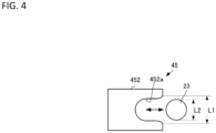
- the engagement mechanism 45 includes an engagement plate 452 including a recessed portion 452a at a tip portion in an advancing direction of the arm mechanism 41, the recessed portion 452a that can be fitted to the second column support 23 (column support member) of the creel stand 2, and is configured to engage with the creel stand 2 by fitting the recessed portion 452a of the engagement plate 452 to the second column support 23 of the creel stand 2.
- the creel robot 1 merely uses a simple configuration and operation of fitting the recessed portion 452a of the engagement plate 452 to the second column support 23 of the creel stand 2, and thereby the engagement mechanism 45 can be engaged with the creel stand 25, making it possible to change the rotation angle of the peg 25 with high accuracy at the time of rotationally driving around the vertical axis of the creel stand 2 as the rotational axis.
- the engagement mechanism 45 includes: the pin member 453 pivotally supporting a rear end portion in the engagement plate 452, and having a central axis that is orthogonal to an advancing/retreating direction of the arm mechanism 41, the central axis matched to an orthogonal direction with respect to the vertical direction; and an engagement cylinder 451 as the posture switching mechanism rotatably coupled between a pivotally supporting position by the pin member 453 of the engagement plate 452 and a formation position of the recessed portion 452a, the posture switching mechanism configured to switch between a lateral posture taken when the arm mechanism 41 advances/retreats and a longitudinal posture taken when the arm mechanism 41 is on standby by rotating the engagement plate 452 around the pin member 453 as the rotational axis.
- the length of the engagement mechanism 45 in the advancing/retreating direction can be shortened by retreating the cylinder rod of the engagement cylinder 451 to set the engagement plate 452 to the longitudinal posture. Consequently, it is possible to prevent the engagement mechanism 45 from being an obstacle when the creel robot 1 moves.
- the recessed portion 452a of the engagement plate 452 is opened with a larger size L1 than a diameter L2 of the second column support 23 (column support member) of the creel stand 2 and is gradually reduced from the opening to a middle of a bottom to a size equal to the diameter L2 of the second column support 23 (column support member). Consequently, since the recessed portion 452a of the engagement plate 452 is opened with the larger size L1 than the diameter L2 of the second column support 23 when the recessed portion 452a of the engagement plate 452 is fitted to the second column support 23 of the creel stand 2, the recessed portion 452a of the engagement plate 452 can be fitted to the second column support 23 even when there is some position misalignment.
- the engagement mechanism 45 is provided at the tip portion of the arm mechanism 41, and the engagement mechanism 45 performs advancing/retreating movement in conjunction with the advancing/retreating movement of the arm mechanism 41, but it is not limited to such an example.
- the engagement mechanism 45 may be configured to being capable of advancing/retreating movement with respect to the creel stand 2 independently from the arm mechanism 41.
- the engagement mechanism 45 is capable of advancing/retreating movement with a movement amount and movement timing independent from a movement amount and movement timing of advancing/retreating movement by the arm mechanism 41.
- a position of the engagement mechanism 45 at the time of the non-connection state can be set within a range of a total length of the arm mechanism 41.
- the engagement mechanism 45 is engaged with the creel stand 2 in advance to fix a positional relationship between the arm mechanism 41 and the creel stand 2, and then the peg driving mechanism 46 is connected to the peg 25, thereby stabilizing the connection state thereto.
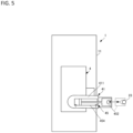
- the engagement mechanism 45 may be configured to provide the engagement advancing/retracting mechanism 454 in the housing 411 of the arm mechanism 41, and to perform advancing/retreating movement of the engagement plate 452 with respect to the second column support 23 of the creel stand 2 by the engagement advancing/retracting mechanism 454.
- the engagement advancing/retracting mechanism 454 may be exemplified as: a configuration in which the engagement plate 452 is connected to the tip portion of a cylinder rod of a cylinder device such as a hydraulic cylinder or an air cylinder; a configuration in which a pinion rotationally driven by a motor is meshed with a rack to made it possible to perform advancing/retreating movement and the engagement plate 452 is connected to a tip portion of the rack; and a configuration in which the engagement plate 452 is connected to a nut member screwed in a screw rotationally driven by a motor.
- the engagement portion between the engagement mechanism 45 and the creel stand 2 is fixed so as not to be rotatable. In this case, since even when the inertial force acts on the arm mechanism 41 when the peg 25 rotates or stops, it will not rotate around the engagement point between the peg drive mechanism 46 and the creel stand 2 as a fulcrum, sway of the arm mechanism 41, the peg driving mechanism 46, and the like can be strongly prevented.
- the engagement mechanism 45 may be exemplified as a configuration in which the recessed portion 452a of the engagement plate 452 is formed in a rounded rectangular shape with rounded rectangular corners, and the cross-sectional shape of the second column support 23 of the creel stand 2 is formed in a rounded rectangular shape.
- the recessed portion 452a of the engagement plate 452 is fitted to the second column support 23, a side surface of the recessed portion 452a and a side surface of the second column support 23 are in contact with each other in a linear shape in the horizontal direction, the second column support 23 can prevent the engagement plate 452 from rotating.
- the engagement mechanism 45 may further includes a stand-side engagement member 457 that is provided on the creel stand 2 and is engaged with the engagement plate 452 of the engagement mechanism 45. In this case, an amount of advancement of the arm mechanism 41 for engaging the engagement mechanism 45 with the creel stand 2 can be adjusted by the stand-side engagement member 457.
- the engagement mechanism 45 may be exemplified as a configuration including the engagement plate 452 having the recessed portion 452a and the creel stand 2 having a stand-side engagement member 457 including a convex fitting portion 457a fitted to the recessed portion 452a of the engagement plate 452.
- the stand-side engagement member457 has a through hole 457b through which the second column support 23 is inserted, is dividable into a plurality of members, and the through hole 457b is formed of the plurality of members.
- the stand-side engagement member 457 when attaching the stand-side engagement member 457 to the second column support 23 of the already-existing creel stand 2, the stand-side engagement member 457 can be attached to the second column support 23 without removing a part of the second column support 23 by arranging the plurality of members around the second column support 23 and forming the through hole 457b by bonding the plurality of arranged members.
- the stand-side engagement member 457 has a through hole 457b through which the second column support 23 is inserted, and is dividable into a first member 4571 disposed on the engagement plate 452 side and a second member 4572 disposed on the opposite side to the engagement plate 452 side; and the through hole 457b is formed of these first member 4571 and second member 4572.
- the stand-side engagement member 457 includes fastening bolts 4573, 4573 disposed on both sides of the second member 4572 that sandwich the through hole 457b, and the first member 4571 and the second member 4572 are fastened to each other by screwing these fastening bolts 4573, 4573 respectively into screw holes of the first member 4571.
- the stand-side engagement member 457 includes a fixing bolt 4574 disposed between the fastening bolts 4573, 4573 of the second member 4572, and a tip portion of the fixing bolt 4574 is pressed against the second column support 23. In this case, since the stand-side engagement member 457 is strongly fixed to the second column support 23, position misalignment of the stand-side engagement member 457 can be prevented.
- the engagement mechanism 45 illustrated in FIG. 7 has a configuration of including the engagement plate 452 having the recessed portion 452a and the stand-side engagement member 457 having the convex fitting portion 457a, but it is not limited to such an example. Namely, as illustrated in FIG. 8 , the engagement mechanism 45 may have a configuration of including an engagement plate 452 having a convex fitting portion 452b and a stand-side engagement member 457 having a recessed portion 457c.
- the creel stands 2 illustrated in FIG. 2 are disposed on both sides in the X direction with respect to the creel robot 1 (the upper side and the lower side of the creel robot 1 in FIG. 2 ).
- one creel robot 1 is configured to be capable of supplying yarn feeding packages to both of the two creel stands 2, 2 disposed on both sides in the X direction.
- the creel robot 1 may be configured to be capable of supplying the yarn feeding package to the creel stand 2 disposed at one side in the X direction.
- the "yarn” has been described as the case of being used for the false-twist texturing of synthetic fibers such as polyester, but it is not limited to such an example.
- the "yarn” may be synthetic fibers such as nylon or rayon, natural fibers such as cotton, wool, or silk, or film fibers such as polyvinyl chloride, polyurethane, or Teflon (R) formed into film form.
- the "yarn feeding package” may be used in a manufacturing process of woven fabrics or knitted fabrics, such as a weaving machine and knitting machine, in addition to the false twisting machine.
Landscapes
- Replacing, Conveying, And Pick-Finding For Filamentary Materials (AREA)
Abstract
To provide a creel robot capable of changing a rotation angle of a peg around a vertical axis of a creel stand as a rotational axis with high accuracy and capable of facilitating supplying of a yarn feeding package to the creel side and collecting of an empty take-up tube. The creel robot includes: a peg driving mechanism 46 configured to rotationally drive the peg 25 around a vertical direction as a rotational axis; an arm mechanism 41 in which the peg driving mechanism 46 is provided, the arm mechanism configured to be switchable between a connection state for a transmitting rotary driving force of the peg driving mechanism 46 to the peg 25 by advancing and connecting to the peg 25 and a non-connection state for transmitting no rotary driving force of the peg driving mechanism 46 to the peg 25 by separating and retreating from the peg 25; and an engagement mechanism 45 provided in the arm mechanism 41 and configured to be engaged with the creel stand 2 during the connection state of the peg driving mechanism 46.
Description
- The present invention relates to a creel robot.
- Regarding a technology of a creel robot configured to supply a yarn feeding package to a peg of a creel stand for holding a yarn feeding package in which a yarn is wound around an empty take-up tube and to collect the empty take-up tube,
Patent document 1 discloses a technology for forming a yarn-feeding changing robot of a traveling carriage traveling on rails serving as a carriage traveling path, a yarn-feeding changer movably arranged up and down relative to the traveling carriage, and a workbench moving up and down in turn with the yarn-feeding changer, configured so that a peg shaft of a creel is rotated by a peg open mechanism of the yarn-feeding changer based on a vertical axis of a creel stand as a rotational axis, and in a state of being stopped at a predetermined rotation angle, a full package is supplied to the creel side by a yarn-feeding changing mechanism. - Patent Document 1:
Japanese Patent Application Publication No. H06-056349 - Incidentally, when the peg shaft of the creel is rotated around the vertical axis of the creel stand as the rotational axis and is stopped at the predetermined rotation angle, the peg open mechanism of the yarn-feeding changer and the like sway due to an inertial force at the time of start and end of rotation due to a weight of the yarn feeding package, thereby making it difficult to stop the peg shaft at the predetermined rotation angle. Consequently, stopping accuracy decreases regarding the rotation angle of the peg as around the vertical axis of the creel stand as the rotational axis, and there is room for an improvement in that such decreased stopping accuracy makes it difficult for the yarn-feeding changing mechanism to supply the full package to the creel side.
- The present invention has been made in view of the above-described technical problems, and an object thereof is to provide a creel robot capable of changing a rotation angle of a peg around a vertical axis of a creel stand as a rotational axis with high accuracy and capable of facilitating to supply a yarn feeding package to the creel side and to collect an empty take-up tube.
- A first aspect of the present invention is a creel robot capable of advancing/retreating movement with respect to a creel stand for supporting a peg that can hold a yarn feeding package around which a yarn is wound,
- the creel robot configured to supply the yarn feeding package to the peg,
- the creel robot comprising:
- a peg driving mechanism configured to rotationally drive the peg around a vertical direction as a rotational axis;
- an arm mechanism in which the peg driving mechanism is provided, the arm mechanism configured to be switchable between a connection state for a transmitting rotary driving force of the peg driving mechanism to the peg by advancing and connecting to the peg and a non-connection state for transmitting no rotary driving force of the peg driving mechanism to the peg by separating and retreating from the peg; and
- an engagement mechanism provided in the arm mechanism and configured to be engaged with the creel stand during the connection state of the peg driving mechanism.
- According to the above-described first aspect of the creel robot, when the peg driving mechanism provided in the arm mechanism is shifted to the connection state with respect to the peg by advancing the arm mechanism, and the rotary driving force of the peg driving mechanism is transmitted to the peg and the peg is rotated around the vertical axis of the creel stand as the rotational axis, an inertial force at the time of rotating is occur at a portion where the peg driving mechanism is installed in the arm mechanism. However, the engagement mechanism is engaged with the creel stand during the connection state of the peg driving mechanism, and therefore it is possible to prevent sway of the peg open mechanism and the like in the yarn-feeding changer due to the inertial force. Consequently, since it becomes possible to change the rotation angle of the peg with high accuracy at the start and end of rotation of the peg around the vertical axis of the creel stand as the rotational axis, it is possible to facilitate the supply of the yarn feeding package around which the yarn is wound and the collection of the empty take-up tube.
- A second aspect of the present invention is the creel robot in the above-described first aspect, wherein preferably
- the creel stand includes a column support member longitudinally provided in the vertical direction, wherein
- the engagement mechanism includes an engagement plate including a recessed portion at a tip portion in an advancing direction of the arm mechanism, and the recessed portion that can be fitted to the column support member of the creel stand, the engagement mechanism configured to engage with the creel stand by fitting the recessed portion of the engagement plate to the column support member of the creel stand.
- According to the above-described second aspect of the creel robot, by using a simple configuration and operation of fitting the recessed portion of the engagement plate to the column support member of the creel stand, the engagement mechanism can be engaged with the creel stand, making it possible to change the rotation angle of the peg with high accuracy at the time of rotationally driving around the vertical axis of the creel stand as the rotational axis.
- A third aspect of the present invention is the creel robot in the above-described second aspect, wherein preferably the engagement mechanism includes:
- a pin member pivotally supporting a rear end portion in the engagement plate, the pin member having a central axis that is orthogonal to an advancing/retreating direction of the arm mechanism, the central axis matched to an orthogonal direction with respect to the vertical direction; and
- a posture switching mechanism rotatably coupled between a pivotally supporting position by the pin member of the engagement plate and a formation position of the recessed portion, the posture switching mechanism configured to switch between a lateral posture taken when the arm mechanism advances/retreats and a longitudinal posture taken when the arm mechanism is on standby by rotating the engagement plate around the pin member as a rotational axis.
- According to the above-described third aspect of the creel robot, when the peg is not rotated, a length of the engagement mechanism in the advancing/retreating direction can be shortened by setting the engagement plate in the longitudinal posture by the posture switching mechanism. Consequently, it is possible to prevent the engagement mechanism from being an obstacle when the creel robot moves.
- A fourth aspect of the present invention is the creel robot in any one of the above-described preceding aspects, wherein preferably the recessed portion of the engagement plate is opened with a larger size than a diameter of the column support member of the creel stand and is gradually reduced from the opening to a middle of a bottom to a size equal to the diameter of the column support member.
- According to the above-described fourth aspect of the creel robot, since the recessed portion of the engagement plate is opened with the larger size than the diameter of the column support member when the recessed portion of the engagement plate is fitted to the column support member of the creel stand, the recessed portion of the engagement plate can be fitted to the column support member even when there is some position misalignment.
- A fifth aspect of the present invention is the creel robot in any one of the above-described preceding aspects, wherein preferably the engagement mechanism is capable of advancing/retreating movement with respect to the creel stand independently from the arm mechanism.
- According to the above-described fifth aspect of the creel robot, the engagement mechanism is capable of advancing/retreating movement with a movement amount and movement timing independent from a movement amount and movement timing of advancing/retreating movement by the arm mechanism. Consequently, for example, by moving the engagement mechanism with a larger movement amount than that of the arm mechanism, a position of the engagement mechanism at the time of the non-connection state can be set within a range of a total length of the arm mechanism. Moreover, the engagement mechanism is engaged with the creel stand in advance to fix a positional relationship between the arm mechanism and the creel stand, and then the peg driving mechanism is connected to the peg, thereby stabilizing the connection state thereto.
- A sixth aspect of the present invention is the creel robot in any one of the above-described preceding aspects, wherein preferably the peg includes:
- an externally fitted member provided rotatably around the vertical direction as the rotational axis and externally fitted to the column support member;
- a yarn feeding package holding mechanism provided on the externally fitted member and holding the yarn feeding package; and
- a rotation transmission unit that enables to transmit, to the peg, the rotary driving force from the peg driving mechanism around the vertical direction as the rotational axis, wherein
- when the arm mechanism is in the connection state, the peg driving mechanism and the rotation transmission unit are connected to each other, and the peg driving mechanism performs rotationally driving, and thereby the externally fitted member rotates around the vertical direction as the axis, changing an orientation in a horizontal direction of the yarn feeding package holding mechanism.
- According to the above-described sixth aspect of the creel robot, it becomes possible to change the orientation in the horizontal direction of the package holding mechanism while preventing of the yarn-feeding changer from the sway due to the inertial force, even with a simple configuration of merely connecting the peg driving mechanism and the rotation transmission unit to rotationally drive the peg driving mechanism.
- A seventh aspect of the present invention is the creel robot in any one of the above-described preceding aspects, preferably further comprising a stand-side engagement member provided on the creel stand and engaged with the engagement mechanism.
- According to the above-described seventh aspect of the creel robot, an amount of advancement for engaging the engagement mechanism with the creel stand can be adjusted by the stand-side engagement member.
- The creel robot according to the present invention may be formed of merely the configuration described as the creel robot described in the above-described first aspect, or may be formed of freely combining the configuration described in the above-described first aspect with the configuration(s) described in any of the above-described second to seventh aspects, to the extent that consistency can be achieved. When combining the configuration described in the above-described first aspect with the configuration(s) described in any of the above-described second to seventh aspects, all or part of the configuration described in the above-described first aspect can be combined with all or part of configurations of described in the above-described second to seventh aspects, to the extent that consistency can be achieved.
- (Advantageous Effects of the Invention)
- According to the present invention, it is possible to provide a creel robot capable of changing a rotation angle of a peg around a vertical axis of a creel stand as a rotational axis with high accuracy and capable of facilitating supplying of a yarn feeding package and collecting of an empty take-up tube.
-
-
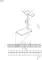
FIG. 1 is an explanatory view illustrating a relationship between a yarn-feeding changer and a creel stand. -
FIG. 2 is an explanatory view illustrating a relationship between a creel robot and the creel stand. -
FIG. 3 is a perspective view of the yarn-feeding changer. -
FIG. 4 is an explanatory view illustrating a relationship between an engagement plate of an engagement mechanism and a second column support. -
FIG. 5 is a plan view illustrating a state where the creel robot is provided with an engagement advancing/retracting mechanism. -
FIG. 6 is an explanatory view illustrating a relationship between the engagement plate of the engagement mechanism and the second column support. -
FIG. 7 is an explanatory view illustrating a relationship between the engagement plate of the engagement mechanism and a stand-side engagement member. -
FIG. 8 is an explanatory view illustrating a relationship between the engagement plate of the engagement mechanism and the stand-side engagement member. - Hereinafter, embodiments for carrying out the present invention will be described with reference to the drawings. In the following description, a "Z direction" illustrated in the diagrams corresponds to a vertical direction (up-and-down direction) and an "X direction" corresponds to a horizontal direction. A "Y direction" corresponds to a horizontal direction orthogonal to the "X direction" and is also orthogonal to the Z direction.
- A "
creel stand 2" illustrated inFIG. 1 is provided for a false-twist texturing process of synthetic fibers. Thecreel stand 2 is configured to support apeg 25 capable of holding a yarn feeding package around which a yarn is wound. As illustrated as a specific example, thecreel stand 2 includes acreel base 21, and afirst column support 22, asecond column support 23, apartition plate 24, and apeg 25. Thecreel base 21 is disposed on a floor surface or the like, and supports thefirst column support 22 and thesecond column support 23. Thefirst column support 22 and thesecond column support 23 are longitudinally provided on thecreel base 21. Thefirst column support 22 extends along the Z direction (vertical direction). The first column supports 22 are arrayed at equal intervals in the Y direction. The First column supports 22 are disposed on one side F1 in the X direction in thecreel stand 2. Thesecond column support 23 extends along the Z direction. The second column supports 23 are disposed in pairs in the Y direction, and a plurality of pairs of second column supports 23, 23 are arranged in the Y direction. Thesecond column support 23 supports thepeg 25 so as to be rotatable around thesecond column support 23 as a rotational axis and is disposed on the other side F2 in the X direction in thecreel stand 2. The other side F2 in the X direction is a side along which thecreel robot 1 travels and is a side where an operator who performs a yarn splicing operation works. Thepartition plate 24 is provided so as to extend across thefirst column support 22 and thesecond column support 23. Thepartition plates 24 are plate-shaped members and are disposed to be spaced at predetermined intervals in the Z direction. Thepartition plate 24 prevents the yarn feeding package from falling off thepeg 25. - As illustrated in
FIG. 2 , the present embodiment describes the case where the other sides F2, F2 in the X direction in two creel stands 2, 2 are arranged opposite to each other, and thecreel robot 1 disposed between the creel stands 2, 2 is configured to be able to travel along the creel stands 2, 2. However, the present invention is not limited to such a case, and thecreel robot 1 may be configured to travel along asingle creel stand 2. - As illustrated in
FIG. 2 , thecreel robot 1 is capable of advancing/retreating movement in the X direction with respect to thecreel stand 2 for supporting the peg 25 (refer toFIG. 1 ) capable of holding a yarn feeding package around which a yarn is wound, and is configured to supply the yarn feeding package to thepeg 25. Specifically, thecreel robot 1 includes: a yarn-feeding changer 4; a travelingmechanism 11 that is disposed between the creel stands 2, 2 and travels along the creel stands 2, 2; an up-and-down mechanism 12 that is longitudinally provided on travelingmechanism 11 and moves up and down the yarn-feeding changer 4 in an up-and-down direction; and abridging mechanism 13 that is provided at an upper end portion of the up-and-down mechanism 12 and is bridged over the creel stands 2, 2 in order to stabilize a distance between the up-and-down mechanism 12 and the creel stands 2, 2. Thecreel robot 1 is capable of performing a process of transporting the yarn feeding package stored in a raw yarn storage unit, which is not illustrated, to thecreel stand 2 to be supplied to eachpeg 25, and a process of collecting, after all the yarns are unwound from the yarn feeding package, empty take-up tubes around which the yarn is not wound from thepeg 25 and supplying the collected empty take-up tubes into an empty take-up tube collection box through an empty take-up tube collection chute, which is not illustrated. - The "yarn" used herein is exemplified by synthetic fibers, such as polyester. The "yarn feeding package" is a winding-type package for supplying a yarn (synthetic fiber) used in a manufacturing process, such as a false-twist texturing machine. The yarn feeding package is composed of a take-up tube having a cylindrical shape of a center part, and the yarn wound around the take-up tube, and is held by inserting the
peg shaft 251 of thepeg 25 inside the take-up tube. - Returning to
FIG. 1 , thepeg 25 supports the yarn feeding package. Thepeg 25 is provided on thesecond column support 23. A plurality ofpegs 25 are disposed to be spaced at predetermined intervals in the Z direction on thesecond column support 23. Thepeg 25 is disposed between twopartition plates 24 in the Z direction. Thepegs 25 are arranged in pairs corresponding to the second column supports 23, 23 arranged in a pair, and a plurality of pairs ofpegs pegs 25 are connected to each other, and thereby a single yarn is continuously supplied from two yarn feeding packages each supported by the pair ofpegs processing unit 3 which performs false-twist texturing and the like. - The
peg 25 includes a pair ofpeg shafts peg body member 252, an externally fittedmember 253, and arotation transmission member 254. The pair ofpeg shafts peg shafts peg shafts peg shafts peg body member 252. Thesecond column support 23 of thecreel stand 2 is inserted into thepeg body member 252, and thereby thepeg shafts - A lower end portion of the externally fitted
member 253 formed in a cylindrical shape is connected to thepeg body member 252. Thesecond column support 23 of thecreel stand 2 is inserted into the externally fittedmember 253. In contrast, therotation transmission member 254 is connected to an upper end portion of the externally fittedmember 253. Therotation transmission member 254 is formed in a gear shape of a Geneva wheel constituting a Geneva mechanism, and agear part 254a is formed in a wave shape or an arc shape. Therotation transmission member 254 is rotated by driving thepeg driving mechanism 46 described below to rotate thepeg body member 252 through the externally fittedmember 253, thereby, rotating thepeg shafts peg body member 252 at a predetermined rotation angle. Consequently, thepeg 25 can be rotated between a first rotation state; a second rotation state; and a third rotation state. The first rotation state is a state of a rotation angle where the yarn feeding package is supported so that the yarn can be supplied to theprocessing unit 3 that performs false twisting of the yarn. The second rotation state is a state of a rotation angle where the yarn feeding package is supported so that the yarn feeding package can be changed (so that the take-up tube can be collected and the yarn feeding package can be attached). The third rotation state is a state of a rotation angle where the yarn feeding package is attached to thepeg 25 being in the second rotation state and then is directed in one direction between the first rotation state and the second rotation state. It is to be noted that since the third rotation state has the rotation angle different from those of the first rotation state and the second rotation state, it is possible to easily let the operator recognize that the yarn splicing operation is not completed and is possible to prevent operator from overlooking the operation after the yarn feeding package is attached to thepeg 25. - In more details, in a first rotation state where a tip portion of the
peg shaft 251 faces thecreel robot 1 side and a shaft center of thepeg shaft 251 intersects with an inclination angle of approximately 45 degrees with respect to the X direction, the yarn is unwound from the yarn feeding package supported by thepeg shaft 251 and is supplied to theprocessing unit 3. Subsequently, when all the yarns are unwound from the yarn feeding package, and thepeg shaft 251 supports an empty take-up tube around which no yarn is wound, the tip portion of thepeg shaft 251 faces the other side F2 in the X direction and the shaft center of thepeg shaft 251 is rotated so as to be matched to the X direction, and thereby thepeg 25 is shifted to the second rotation state. Then, during the second rotation state, the empty take-up tube, which is a used yarn feeding package, is extracted from thepeg shaft 251, and is changed to an unused yarn feeding package. - The tip portion of the
peg shaft 251 then faces the Y direction, and thepeg 25 is rotated so that the shaft center of thepeg shaft 251 is orthogonal to the X direction. Consequently, thepeg 25 is in the third rotation state, which is one rotation state between the first rotation state and the second rotation state. The yarn feeding package supported by thepeg 25 in the third rotation state looks significantly different from the yarn feeding package supported by thepeg 25 in the first rotation state, when viewed from thecreel robot 1 side. Therefore, the operator can recognize thepeg 25 located in the third rotation state in distinction from thepeg 25 located in the first rotation state or the second rotation state. In other words, the operator can easily recognize the yarn feeding package supported by thepeg 25 for which the attachment work of the yarn feeding package has been completed but the yarn splicing operation has not yet been completed and these operations should be performed. - As illustrated in
FIG. 3 , thecreel robot 1 includes a yarn-feeding changer 4. The yarn-feeding changer 4 includes anarm mechanism 41, a yarn feedingpackage holding mechanism 43, arotation mechanism 42 configured to independently rotate thearm mechanism 41 and the yarn feedingpackage holding mechanism 43, and an empty take-up tubeaccommodating mechanism 44. - The
rotation mechanism 42 includes afirst motor 421 and asecond motor 423 arranged in parallel to each other. Thefirst motor 421 and thesecond motor 423 are arranged so that a shaft center of a motor rotational axis is matched to a traveling direction of the creel robot 1 (Y direction). A first rotationaldirection changing mechanism 422 and a second rotationaldirection changing mechanism 424 each configured to change a rotational direction of a motor rotational axis into an orthogonal direction are respectively coupled with the motor rotational axes of afirst motor 421 and thesecond motor 423. Afirst gear 425 and asecond gear 426 horizontally arranged are respectively meshed with gears on output side of the first rotationaldirection changing mechanism 422 and the second rotationaldirection changing mechanism 424. Thefirst gear 425 and thesecond gear 426 are arranged so as to overlap each other in the up-and-down direction such that thefirst gear 425 is located above thesecond gear 426, and rotational axes thereof are set in the vertical direction and are matched to each other. - One end of the
arm mechanism 41 is provided on an upper surface of thefirst gear 425. The rotational axis of thearm mechanism 41 is matched to the rotational axis of afirst gear 425, and thefirst gear 425 rotates the other end of thearm mechanism 41 around the rotational axis. In contrast, one end of the yarn feedingpackage holding mechanism 43 is provided on a lower surface of thesecond gear 426. A rotational axis of the yarn feedingpackage holding mechanism 43 is matched to the rotational axis of asecond gear 426, and thesecond gear 426 rotates the other end of the yarn feedingpackage holding mechanism 43 around the rotational axis. - The yarn feeding
package holding mechanism 43 has a pair of rod-like members mechanism support body 432 that supports the rod-like members like members mechanism support body 432 and are horizontally arranged. Moreover, the rod-like members package holding mechanism 43 is configured to hold the yarn feeding package by inserting the pair of rod-like members mechanism support body 432 is coupled to a lower surface of thesecond gear 426 in a portion, which is the other end of the yarn feedingpackage holding mechanism 43. - An empty take-up tube
accommodating mechanism 44 is provided on a lower surface of the holdingmechanism support body 432. Consequently, the empty take-up tubeaccommodating mechanism 44 rotates together with the yarn feedingpackage holding mechanism 43. The empty take-up tubeaccommodating mechanism 44 includes an empty take-uptube accommodating box 441 configured to accommodate an empty take-up tube after all yarns are unwound. The empty take-uptube accommodating box 441 has a box shape which is rectangular in planar view, surrounded by walls on three side among four horizontal sides thereof, and is opened in one direction where no wall is formed among the horizontal four sides. An opening direction in the empty take-uptube accommodating box 441 has a relationship of being shifted by approximately 90 degrees in planar view with respect to a direction in which tips of the rod-like members package holding mechanism 43 face. For example, when the tip of the yarn feedingpackage holding mechanism 43 faces in a front direction, the opening direction of the empty take-uptube accommodating box 441 corresponds to a right side direction, and when the tip of the yarn feedingpackage holding mechanism 43 faces to a left side, the opening direction of the empty take-uptube accommodating box 441 correspond to the front direction. - Moreover, the empty take-up tube
accommodating mechanism 44 includes an accommodating boxrotational driving mechanism 442 configured to tilt the empty take-uptube accommodating box 441. The accommodating boxrotational driving mechanism 442 can move the empty take-up tube toward the wall by rotating the empty take-uptube accommodating box 441 so as to be an inclination posture in which the opening faces to the upper side, when the empty take-up tube is accommodated in the empty take-uptube accommodating box 441. On the other hand, the accommodating boxrotational driving mechanism 442 can move the empty take-up tube toward the opening by rotating the empty take-uptube accommodating box 441 so as to be an inclination posture in which the opening faces to the lower side. - One end of the
arm mechanism 41 is provided on the upper surface of thefirst gear 425 in therotation mechanism 42. The rotational axis of thearm mechanism 41 is matched to the rotational axis of thefirst gear 425, and thefirst gear 425 rotates the other end (tip portion) of thearm mechanism 41 around the rotational axis. Apeg driving mechanism 46 and anengagement mechanism 45 are provided on the other end (tip portion) of thearm mechanism 41. Thearm mechanism 41 is configured to be switchable between a connection state for a transmitting rotary driving force of thepeg driving mechanism 46 to thepeg 25 by advancing and connecting to thepeg 25 and a non-connection state for transmitting no rotary driving force of thepeg driving mechanism 46 to thepeg 25 by separating and retreating from thepeg 25. - Specifically, the
arm mechanism 41 includes: ahousing 411 having accommodating space inside thereof and an opening at the other end side (tip side) toward thepeg 25 direction; a horizontal supportingmember 414 provided on a bottom wall of thehousing 411 and extending in a horizontal direction from the opening; a longitudinal supportingmember 415 longitudinally provided at a tip portion of the horizontal supportingmember 414; and acylinder member 412 for arm and aguide bar 413 each provided in thehousing 411. One end side of both thecylinder member 412 for arm and theguide bar 413 is fixed to thehousing 411. Acylinder rod 412a of thecylinder member 412 for arm and the other end side (tip side) of theguide bar 413 are exposed from the opening of thehousing 411. A tip portion of thecylinder rod 412a of thecylinder member 412 for arm is fixed to the longitudinal supportingmember 415. On the other hand, the other end side (tip side) of theguide bar 413 is slidably supported by the longitudinal supportingmember 415. As a result, while the direction of the advancing/retreating movement is regulated by theguide bar 413, thearm mechanism 41 can advance and retreat thepeg driving mechanism 46 and theengagement mechanism 45 provided at the other end (tip portion) in the X direction with respect to thepeg 25 by the advancing/retreating movement of thecylinder rod 412a in thecylinder member 412 for arm. Theengagement mechanism 45 can be engaged with thecreel stand 2 as described below, but as long as theengagement mechanism 45 can be engaged with thecreel stand 2, the direction in which thepeg driving mechanism 46 and theengagement mechanism 45 advance and retreat with respect to thepeg 25 is not limited to the X direction, i.e., the horizontal direction. For example, thepeg driving mechanism 46 and theengagement mechanism 45 may be adapted to advance and retreat with respect to thepeg 25 at a predetermined angle with respect to the horizontal direction (angle at which theengagement mechanism 45 can be engaged with the creel stand 2). - Moreover, the
cylinder member 412 for arm and theguide bar 413 are arranged on one end in a width direction of thearm mechanism 41. Consequently, thearm mechanism 41 prevents theengagement mechanism 45 from upsizing by making it possible to dispose thepeg driving motor 462 at the center portion in the width direction and to dispose theengagement mechanism 45 on the other end in the width direction. - The
peg driving mechanism 46 is configured to rotationally drive thepeg 25 around the vertical direction as a rotational axis. Specifically, thepeg driving mechanism 46 includes: apeg driving plate 463 having a rotational axis in the vertical direction and having a star shape in top surface view; and a plurality ofrotating rollers 461, each disposed at a top portion of thepeg driving plate 463. A pitch of therotating roller 461 is matched to a pitch of thegear part 254a of therotation transmission member 254 in thepeg 25. Consequently, thepeg driving mechanism 46 realizes smooth movement and low friction when therotating roller 461 is in contact with thegear part 254a of therotation transmission member 254 of thepeg 25 and is meshed with the gear. - A
peg driving motor 462 is disposed above thepeg driving plate 463. Thepeg driving motor 462 is provided on the horizontal supportingmember 414. Thepeg driving motor 462 is disposed at a center portion in a width direction of thearm mechanism 41 and is disposed at sides of thecylinder rod 412a and theguide bar 413 of thepeg driving mechanism 46. A rotational axis of the rotary shaft of thepeg driving motor 462 is matched to a rotational axis of thepeg driving plate 463. The rotary shaft of thepeg driving motor 462 is connected to thepeg driving plate 463 and is configured to rotationally drive thepeg driving plate 463 at a predetermined rotation angle. Consequently, it is possible for thepeg driving mechanism 46 to stoppably rotate thepeg 25 through therotation transmission member 254 at rotation angles among the first rotation state, the second rotation state, and the third rotation state. - As described above, the
peg 25 in thecreel robot 1 includes: an externally fittedmember 253 provided rotatably around the vertical direction as the rotational axis and externally fitted to thesecond column support 23, which is a column support member; a yarn feedingpackage holding mechanism 43 provided on the externally fittedmember 253 and holding the yarn feeding package; and arotation transmission member 254 that enables to transmit, to thepeg 25, the rotary driving force from thepeg driving mechanism 46 around the vertical direction as the rotational axis, wherein when thearm mechanism 41 is in the connection state, thepeg driving mechanism 46 and therotation transmission member 254 are connected to each other, and thepeg driving mechanism 46 performs rotationally driving, and thereby the externally fittedmember 253 rotates as the axis around the vertical direction, changing an orientation in a horizontal direction of the yarn feedingpackage holding mechanism 43. - The
engagement mechanism 45 is provided in thearm mechanism 41 and is configured to be engaged with thecreel stand 2 during the connection state of thepeg driving mechanism 46. Consequently, in thecreel robot 1, when thepeg driving mechanism 46 provided in thearm mechanism 41 is shifted to the connection state with respect to thepeg 25 by advancing thearm mechanism 41 in the yarn-feeding changer 4, and the rotary driving force of thepeg driving mechanism 46 is transmitted to thepeg 25 and thepeg 25 is rotated around the vertical axis of thesecond column support 23 of thecreel stand 2 as the rotation axis, an inertial force at the time of rotating or stopping occurs at a portion where thepeg driving mechanism 46 is installed in thearm mechanism 41. However, theengagement mechanism 45 is engaged with thecreel stand 2 during the connection state of thepeg driving mechanism 46, and therefore it is possible to prevent sway of the peg driving mechanism 46 (the peg open mechanism) and the like in the yarn-feeding changer 4 due to the inertial force. Consequently, since it becomes possible to change the rotation angle of thepeg 25 with high accuracy at the start and end of rotation of thepeg 25 around the vertical axis of thecreel stand 2 as the rotational axis, it is possible to facilitate the supply of the yarn feeding package around which the yarn is wound and the collection of the empty take-up tube. - As illustrated as a specific example, the
engagement mechanism 45 includes anengagement plate 452 including a recessedportion 452a at a tip portion in an advancing direction of thearm mechanism 41, the recessedportion 452a that can be fitted to the second column support 23 (column support member) of thecreel stand 2, and is configured to engage with thecreel stand 2 by fitting the recessedportion 452a of theengagement plate 452 to thesecond column support 23 of thecreel stand 2. Consequently, thecreel robot 1 merely uses a simple configuration and operation of fitting the recessedportion 452a of theengagement plate 452 to thesecond column support 23 of thecreel stand 2, and thereby theengagement mechanism 45 can be engaged with thecreel stand 25, making it possible to change the rotation angle of thepeg 25 with high accuracy at the time of rotationally driving around the vertical axis of thecreel stand 2 as the rotational axis. - Moreover, the
engagement mechanism 45 includes: thepin member 453 pivotally supporting a rear end portion in theengagement plate 452, and having a central axis that is orthogonal to an advancing/retreating direction of thearm mechanism 41, the central axis matched to an orthogonal direction with respect to the vertical direction; and anengagement cylinder 451 as the posture switching mechanism rotatably coupled between a pivotally supporting position by thepin member 453 of theengagement plate 452 and a formation position of the recessedportion 452a, the posture switching mechanism configured to switch between a lateral posture taken when thearm mechanism 41 advances/retreats and a longitudinal posture taken when thearm mechanism 41 is on standby by rotating theengagement plate 452 around thepin member 453 as the rotational axis. Consequently, when thepeg 25 is not rotated, the length of theengagement mechanism 45 in the advancing/retreating direction can be shortened by retreating the cylinder rod of theengagement cylinder 451 to set theengagement plate 452 to the longitudinal posture. Consequently, it is possible to prevent theengagement mechanism 45 from being an obstacle when thecreel robot 1 moves. - As illustrated in
FIG. 4 , the recessedportion 452a of theengagement plate 452 is opened with a larger size L1 than a diameter L2 of the second column support 23 (column support member) of thecreel stand 2 and is gradually reduced from the opening to a middle of a bottom to a size equal to the diameter L2 of the second column support 23 (column support member). Consequently, since the recessedportion 452a of theengagement plate 452 is opened with the larger size L1 than the diameter L2 of thesecond column support 23 when the recessedportion 452a of theengagement plate 452 is fitted to thesecond column support 23 of thecreel stand 2, the recessedportion 452a of theengagement plate 452 can be fitted to thesecond column support 23 even when there is some position misalignment. - In the above description, it is configured so that the
engagement mechanism 45 is provided at the tip portion of thearm mechanism 41, and theengagement mechanism 45 performs advancing/retreating movement in conjunction with the advancing/retreating movement of thearm mechanism 41, but it is not limited to such an example. For example, theengagement mechanism 45 may be configured to being capable of advancing/retreating movement with respect to thecreel stand 2 independently from thearm mechanism 41. In this case, theengagement mechanism 45 is capable of advancing/retreating movement with a movement amount and movement timing independent from a movement amount and movement timing of advancing/retreating movement by thearm mechanism 41. Consequently, for example, by moving theengagement mechanism 45 with a larger movement amount than that of thearm mechanism 41, a position of theengagement mechanism 45 at the time of the non-connection state can be set within a range of a total length of thearm mechanism 41. Moreover, theengagement mechanism 45 is engaged with thecreel stand 2 in advance to fix a positional relationship between thearm mechanism 41 and thecreel stand 2, and then thepeg driving mechanism 46 is connected to thepeg 25, thereby stabilizing the connection state thereto. - As illustrated as a specific example, as illustrated in
FIG. 5 , theengagement mechanism 45 may be configured to provide the engagement advancing/retracting mechanism 454 in thehousing 411 of thearm mechanism 41, and to perform advancing/retreating movement of theengagement plate 452 with respect to thesecond column support 23 of thecreel stand 2 by the engagement advancing/retracting mechanism 454. The engagement advancing/retracting mechanism 454 may be exemplified as: a configuration in which theengagement plate 452 is connected to the tip portion of a cylinder rod of a cylinder device such as a hydraulic cylinder or an air cylinder; a configuration in which a pinion rotationally driven by a motor is meshed with a rack to made it possible to perform advancing/retreating movement and theengagement plate 452 is connected to a tip portion of the rack; and a configuration in which theengagement plate 452 is connected to a nut member screwed in a screw rotationally driven by a motor. - As for the form of engagement between the
engagement mechanism 45 and thecreel stand 2, it is preferable that the engagement portion between theengagement mechanism 45 and thecreel stand 2 is fixed so as not to be rotatable. In this case, since even when the inertial force acts on thearm mechanism 41 when thepeg 25 rotates or stops, it will not rotate around the engagement point between thepeg drive mechanism 46 and thecreel stand 2 as a fulcrum, sway of thearm mechanism 41, thepeg driving mechanism 46, and the like can be strongly prevented. - As illustrated as a specific example, as illustrated in
FIG. 6 , theengagement mechanism 45 may be exemplified as a configuration in which the recessedportion 452a of theengagement plate 452 is formed in a rounded rectangular shape with rounded rectangular corners, and the cross-sectional shape of thesecond column support 23 of thecreel stand 2 is formed in a rounded rectangular shape. In this case, when the recessedportion 452a of theengagement plate 452 is fitted to thesecond column support 23, a side surface of the recessedportion 452a and a side surface of thesecond column support 23 are in contact with each other in a linear shape in the horizontal direction, thesecond column support 23 can prevent theengagement plate 452 from rotating. - As illustrated in
FIG. 7 , theengagement mechanism 45 may further includes a stand-side engagement member 457 that is provided on thecreel stand 2 and is engaged with theengagement plate 452 of theengagement mechanism 45. In this case, an amount of advancement of thearm mechanism 41 for engaging theengagement mechanism 45 with thecreel stand 2 can be adjusted by the stand-side engagement member 457. - As illustrated as a specific example, the
engagement mechanism 45 may be exemplified as a configuration including theengagement plate 452 having the recessedportion 452a and thecreel stand 2 having a stand-side engagement member 457 including a convexfitting portion 457a fitted to the recessedportion 452a of theengagement plate 452. In addition, it is preferable that the stand-side engagement member457 has a throughhole 457b through which thesecond column support 23 is inserted, is dividable into a plurality of members, and the throughhole 457b is formed of the plurality of members. In this case, when attaching the stand-side engagement member 457 to thesecond column support 23 of the already-existingcreel stand 2, the stand-side engagement member 457 can be attached to thesecond column support 23 without removing a part of thesecond column support 23 by arranging the plurality of members around thesecond column support 23 and forming the throughhole 457b by bonding the plurality of arranged members. - More specifically, it is preferable that the stand-
side engagement member 457 has a throughhole 457b through which thesecond column support 23 is inserted, and is dividable into afirst member 4571 disposed on theengagement plate 452 side and asecond member 4572 disposed on the opposite side to theengagement plate 452 side; and the throughhole 457b is formed of thesefirst member 4571 andsecond member 4572. Moreover, it is preferable that the stand-side engagement member 457 includesfastening bolts second member 4572 that sandwich the throughhole 457b, and thefirst member 4571 and thesecond member 4572 are fastened to each other by screwing thesefastening bolts first member 4571. In this case, since thefirst member 4571 and thesecond member 4572 can be easily bonded to each other, an operation of attaching the stand-side engagement member 457 to thesecond column support 23 can be simplified. Furthermore, it is preferable that the stand-side engagement member 457 includes afixing bolt 4574 disposed between thefastening bolts second member 4572, and a tip portion of thefixing bolt 4574 is pressed against thesecond column support 23. In this case, since the stand-side engagement member 457 is strongly fixed to thesecond column support 23, position misalignment of the stand-side engagement member 457 can be prevented. - In addition, the
engagement mechanism 45 illustrated inFIG. 7 has a configuration of including theengagement plate 452 having the recessedportion 452a and the stand-side engagement member 457 having the convexfitting portion 457a, but it is not limited to such an example. Namely, as illustrated inFIG. 8 , theengagement mechanism 45 may have a configuration of including anengagement plate 452 having a convexfitting portion 452b and a stand-side engagement member 457 having a recessedportion 457c. - The creel stands 2 illustrated in
FIG. 2 are disposed on both sides in the X direction with respect to the creel robot 1 (the upper side and the lower side of thecreel robot 1 inFIG. 2 ). Namely, onecreel robot 1 is configured to be capable of supplying yarn feeding packages to both of the two creel stands 2, 2 disposed on both sides in the X direction. However, it is not limited to such an example, but thecreel robot 1 may be configured to be capable of supplying the yarn feeding package to thecreel stand 2 disposed at one side in the X direction. - In the present embodiment, the "yarn" has been described as the case of being used for the false-twist texturing of synthetic fibers such as polyester, but it is not limited to such an example. For example, the "yarn" may be synthetic fibers such as nylon or rayon, natural fibers such as cotton, wool, or silk, or film fibers such as polyvinyl chloride, polyurethane, or Teflon(R) formed into film form. Moreover, the "yarn feeding package" may be used in a manufacturing process of woven fabrics or knitted fabrics, such as a weaving machine and knitting machine, in addition to the false twisting machine.
-
- 1
- Creel robot
- 2
- Creel stand
- 3
- False-twist texturing unit
- 4
- Yarn-feeding changer
- 25
- Peg
- 41
- Arm mechanism
- 42
- Rotation mechanism
- 43
- Yarn feeding package holding mechanism
- 44
- Empty take-up tube accommodating mechanism
- 45
- Engagement mechanism
- 46
- Peg driving mechanism
Claims (4)
- A creel robot (1) capable of advancing/retreating movement with respect to a creel stand (2) for supporting a peg (25) that can hold a yarn feeding package around which a yarn is wound,the creel robot (1) configured to supply the yarn feeding package to the peg (25),the creel robot (1) comprising:a peg driving mechanism (46) configured to rotationally drive the peg (25) around a vertical direction as a rotational axis;an arm mechanism (41) in which the peg driving mechanism (46) is provided, the arm mechanism (41) configured to be switchable between a connection state for a transmitting rotary driving force of the peg driving mechanism (46) to the peg (25) by advancing and connecting to the peg (25) and a non-connection state for transmitting no rotary driving force of the peg driving mechanism (46) to the peg (25) by separating and retreating from the peg (25); andan engagement mechanism (45) provided in the arm mechanism (41) and configured to be engaged with the creel stand (2) during the connection state of the peg driving mechanism (46).
- The creel robot (1) as claimed in claim 1, whereinthe creel stand (2) includes a column support member (a second column support 23) longitudinally provided in the vertical direction, whereinthe engagement mechanism (45) includes an engagement plate (452) including a recessed portion (452a) at a tip portion in an advancing direction of the arm mechanism (41), the recessed portion (452a) that can be fitted to the column support member (the second column support 23) of the creel stand (2), andthe engagement mechanism (45) is engaged with the creel stand (2) by fitting the recessed portion (452a) of the engagement plate (452) to the column support member (the second column support 23) of the creel stand (2).
- The creel robot (1) as claimed in claim 2, whereinthe engagement mechanism (45) includesa pin member (453) pivotally supporting a rear end portion of the engagement plate (452), the pin member (453) having a central axis that is orthogonal to an advancing/retreating direction of the arm mechanism (41), the central axis matched to an orthogonal direction with respect to the vertical direction; anda posture switching mechanism (an engagement cylinder 451) rotatably coupled between a pivotally supporting position by the pin member (453) of the engagement plate (452) and a formation position of the recessed portion (452a, 457c), the posture switching mechanism configured to switch between a lateral posture taken when the arm mechanism (41) advances/retreats and a longitudinal posture taken when the arm mechanism (41) is on standby by rotating the engagement plate (452) around the pin member (453) as a rotational axis.
- The creel robot (1) as claimed in any one of claims 1 to 3, wherein
the engagement mechanism (45) is capable of advancing/retreating movement with respect to the creel stand (2) independently from the arm mechanism (41).
Applications Claiming Priority (1)
| Application Number | Priority Date | Filing Date | Title |
|---|---|---|---|
| JP2023179588A JP2025069699A (en) | 2023-10-18 | 2023-10-18 | Creel Robot |
Publications (1)
| Publication Number | Publication Date |
|---|---|
| EP4541743A1 true EP4541743A1 (en) | 2025-04-23 |
Family
ID=92932907
Family Applications (1)
| Application Number | Title | Priority Date | Filing Date |
|---|---|---|---|
| EP24203597.0A Pending EP4541743A1 (en) | 2023-10-18 | 2024-09-30 | Creel robot |
Country Status (4)
| Country | Link |
|---|---|
| EP (1) | EP4541743A1 (en) |
| JP (1) | JP2025069699A (en) |
| CN (1) | CN119841176A (en) |
| TW (1) | TW202517562A (en) |
Citations (4)
| Publication number | Priority date | Publication date | Assignee | Title |
|---|---|---|---|---|
| JPH0656349A (en) * | 1992-08-07 | 1994-03-01 | Murata Mach Ltd | Lifting gear of yarn feed changer |
| JPH0656349B2 (en) | 1986-09-11 | 1994-07-27 | 株式会社日立製作所 | Leak detector |
| JPH0768010B2 (en) * | 1991-07-26 | 1995-07-26 | 村田機械株式会社 | Yarn feed change system for draw false twisting machine |
| EP4056507A1 (en) * | 2021-03-09 | 2022-09-14 | TMT Machinery, Inc. | Yarn supply package attachment system |
-
2023
- 2023-10-18 JP JP2023179588A patent/JP2025069699A/en active Pending
-
2024
- 2024-09-29 CN CN202411368057.7A patent/CN119841176A/en active Pending
- 2024-09-30 EP EP24203597.0A patent/EP4541743A1/en active Pending
- 2024-10-08 TW TW113138195A patent/TW202517562A/en unknown
Patent Citations (4)
| Publication number | Priority date | Publication date | Assignee | Title |
|---|---|---|---|---|
| JPH0656349B2 (en) | 1986-09-11 | 1994-07-27 | 株式会社日立製作所 | Leak detector |
| JPH0768010B2 (en) * | 1991-07-26 | 1995-07-26 | 村田機械株式会社 | Yarn feed change system for draw false twisting machine |
| JPH0656349A (en) * | 1992-08-07 | 1994-03-01 | Murata Mach Ltd | Lifting gear of yarn feed changer |
| EP4056507A1 (en) * | 2021-03-09 | 2022-09-14 | TMT Machinery, Inc. | Yarn supply package attachment system |
Also Published As
| Publication number | Publication date |
|---|---|
| JP2025069699A (en) | 2025-05-01 |
| CN119841176A (en) | 2025-04-18 |
| TW202517562A (en) | 2025-05-01 |
Similar Documents
| Publication | Publication Date | Title |
|---|---|---|
| EP0182209A1 (en) | Compact creel for large diameter yarn supply packages | |
| EP4541743A1 (en) | Creel robot | |
| CN103508259A (en) | Take-up winder | |
| CN1847486B (en) | Fiber machine | |
| EP4357284B1 (en) | Yarn package knot releasing device, yarn joining processing device, and yarn feeding device | |
| CN221396661U (en) | Full-automatic robot spindle changing machine | |
| JPH0718549A (en) | Braider | |
| JP3413402B2 (en) | Series winding sample warping machine | |
| CN100497144C (en) | Textile machine | |
| CN210619795U (en) | Yarn winding and unwinding device | |
| EP4541744A1 (en) | Creel stand | |
| CN221853789U (en) | Spindle replacing device of full-automatic robot and spindle automatic loading and transporting system | |
| JP2022137785A (en) | Yarn feeding package mounting system | |
| CN217478765U (en) | Rotary feeding rack | |
| EP4197951B1 (en) | Yarn package knot releasing device, yarn joining processing device, and yarn feeding device | |
| CN221274888U (en) | Automatic empty ingot supply warehouse | |
| CN222005542U (en) | Spindle collecting and conveying device | |
| JP2977667B2 (en) | Yarn exchange system with V-shaped creel | |
| CN112919249A (en) | Cutting mechanism for needle and thread processing that can avoid needle and thread that cannot be fixed | |
| CN223780471U (en) | Floor type creel for circular knitting machine | |
| CN221252916U (en) | Feeding mechanism for tube-mounted chip burning and/or testing machine | |
| CN223705931U (en) | Waste silk collecting device for netting machine | |
| JPS6353300B2 (en) | ||
| CN211733405U (en) | Yarn unwinding temporary storage device for loom | |
| EP4541747A1 (en) | Take-up tube collection system and take-up tube collection apparatus |
Legal Events
| Date | Code | Title | Description |
|---|---|---|---|
| PUAI | Public reference made under article 153(3) epc to a published international application that has entered the european phase |
Free format text: ORIGINAL CODE: 0009012 |
|
| STAA | Information on the status of an ep patent application or granted ep patent |
Free format text: STATUS: THE APPLICATION HAS BEEN PUBLISHED |
|
| AK | Designated contracting states |
Kind code of ref document: A1 Designated state(s): AL AT BE BG CH CY CZ DE DK EE ES FI FR GB GR HR HU IE IS IT LI LT LU LV MC ME MK MT NL NO PL PT RO RS SE SI SK SM TR |
|
| STAA | Information on the status of an ep patent application or granted ep patent |
Free format text: STATUS: REQUEST FOR EXAMINATION WAS MADE |
|
| 17P | Request for examination filed |
Effective date: 20251023 |