EP4541709A1 - Liquefied natural gas production facility on gravity-based structures - Google Patents
Liquefied natural gas production facility on gravity-based structures Download PDFInfo
- Publication number
- EP4541709A1 EP4541709A1 EP22948123.9A EP22948123A EP4541709A1 EP 4541709 A1 EP4541709 A1 EP 4541709A1 EP 22948123 A EP22948123 A EP 22948123A EP 4541709 A1 EP4541709 A1 EP 4541709A1
- Authority
- EP
- European Patent Office
- Prior art keywords
- gbs
- installation
- installations
- lng
- gas
- Prior art date
- Legal status (The legal status is an assumption and is not a legal conclusion. Google has not performed a legal analysis and makes no representation as to the accuracy of the status listed.)
- Pending
Links
Images





Classifications
-
- F—MECHANICAL ENGINEERING; LIGHTING; HEATING; WEAPONS; BLASTING
- F25—REFRIGERATION OR COOLING; COMBINED HEATING AND REFRIGERATION SYSTEMS; HEAT PUMP SYSTEMS; MANUFACTURE OR STORAGE OF ICE; LIQUEFACTION SOLIDIFICATION OF GASES
- F25J—LIQUEFACTION, SOLIDIFICATION OR SEPARATION OF GASES OR GASEOUS OR LIQUEFIED GASEOUS MIXTURES BY PRESSURE AND COLD TREATMENT OR BY BRINGING THEM INTO THE SUPERCRITICAL STATE
- F25J1/00—Processes or apparatus for liquefying or solidifying gases or gaseous mixtures
- F25J1/02—Processes or apparatus for liquefying or solidifying gases or gaseous mixtures requiring the use of refrigeration, e.g. of helium or hydrogen ; Details and kind of the refrigeration system used; Integration with other units or processes; Controlling aspects of the process
- F25J1/0243—Start-up or control of the process; Details of the apparatus used; Details of the refrigerant compression system used
- F25J1/0257—Construction and layout of liquefaction equipments, e.g. valves, machines
- F25J1/0269—Arrangement of liquefaction units or equipments fulfilling the same process step, e.g. multiple "trains" concept
-
- F—MECHANICAL ENGINEERING; LIGHTING; HEATING; WEAPONS; BLASTING
- F25—REFRIGERATION OR COOLING; COMBINED HEATING AND REFRIGERATION SYSTEMS; HEAT PUMP SYSTEMS; MANUFACTURE OR STORAGE OF ICE; LIQUEFACTION SOLIDIFICATION OF GASES
- F25J—LIQUEFACTION, SOLIDIFICATION OR SEPARATION OF GASES OR GASEOUS OR LIQUEFIED GASEOUS MIXTURES BY PRESSURE AND COLD TREATMENT OR BY BRINGING THEM INTO THE SUPERCRITICAL STATE
- F25J1/00—Processes or apparatus for liquefying or solidifying gases or gaseous mixtures
- F25J1/0002—Processes or apparatus for liquefying or solidifying gases or gaseous mixtures characterised by the fluid to be liquefied
- F25J1/0022—Hydrocarbons, e.g. natural gas
-
- F—MECHANICAL ENGINEERING; LIGHTING; HEATING; WEAPONS; BLASTING
- F25—REFRIGERATION OR COOLING; COMBINED HEATING AND REFRIGERATION SYSTEMS; HEAT PUMP SYSTEMS; MANUFACTURE OR STORAGE OF ICE; LIQUEFACTION SOLIDIFICATION OF GASES
- F25J—LIQUEFACTION, SOLIDIFICATION OR SEPARATION OF GASES OR GASEOUS OR LIQUEFIED GASEOUS MIXTURES BY PRESSURE AND COLD TREATMENT OR BY BRINGING THEM INTO THE SUPERCRITICAL STATE
- F25J1/00—Processes or apparatus for liquefying or solidifying gases or gaseous mixtures
- F25J1/003—Processes or apparatus for liquefying or solidifying gases or gaseous mixtures characterised by the kind of cold generation within the liquefaction unit for compensating heat leaks and liquid production
- F25J1/0047—Processes or apparatus for liquefying or solidifying gases or gaseous mixtures characterised by the kind of cold generation within the liquefaction unit for compensating heat leaks and liquid production using an "external" refrigerant stream in a closed vapor compression cycle
- F25J1/0052—Processes or apparatus for liquefying or solidifying gases or gaseous mixtures characterised by the kind of cold generation within the liquefaction unit for compensating heat leaks and liquid production using an "external" refrigerant stream in a closed vapor compression cycle by vaporising a liquid refrigerant stream
- F25J1/0055—Processes or apparatus for liquefying or solidifying gases or gaseous mixtures characterised by the kind of cold generation within the liquefaction unit for compensating heat leaks and liquid production using an "external" refrigerant stream in a closed vapor compression cycle by vaporising a liquid refrigerant stream originating from an incorporated cascade
-
- F—MECHANICAL ENGINEERING; LIGHTING; HEATING; WEAPONS; BLASTING
- F25—REFRIGERATION OR COOLING; COMBINED HEATING AND REFRIGERATION SYSTEMS; HEAT PUMP SYSTEMS; MANUFACTURE OR STORAGE OF ICE; LIQUEFACTION SOLIDIFICATION OF GASES
- F25J—LIQUEFACTION, SOLIDIFICATION OR SEPARATION OF GASES OR GASEOUS OR LIQUEFIED GASEOUS MIXTURES BY PRESSURE AND COLD TREATMENT OR BY BRINGING THEM INTO THE SUPERCRITICAL STATE
- F25J1/00—Processes or apparatus for liquefying or solidifying gases or gaseous mixtures
- F25J1/02—Processes or apparatus for liquefying or solidifying gases or gaseous mixtures requiring the use of refrigeration, e.g. of helium or hydrogen ; Details and kind of the refrigeration system used; Integration with other units or processes; Controlling aspects of the process
- F25J1/0211—Processes or apparatus for liquefying or solidifying gases or gaseous mixtures requiring the use of refrigeration, e.g. of helium or hydrogen ; Details and kind of the refrigeration system used; Integration with other units or processes; Controlling aspects of the process using a multi-component refrigerant [MCR] fluid in a closed vapor compression cycle
- F25J1/0212—Processes or apparatus for liquefying or solidifying gases or gaseous mixtures requiring the use of refrigeration, e.g. of helium or hydrogen ; Details and kind of the refrigeration system used; Integration with other units or processes; Controlling aspects of the process using a multi-component refrigerant [MCR] fluid in a closed vapor compression cycle as a single flow MCR cycle
-
- F—MECHANICAL ENGINEERING; LIGHTING; HEATING; WEAPONS; BLASTING
- F25—REFRIGERATION OR COOLING; COMBINED HEATING AND REFRIGERATION SYSTEMS; HEAT PUMP SYSTEMS; MANUFACTURE OR STORAGE OF ICE; LIQUEFACTION SOLIDIFICATION OF GASES
- F25J—LIQUEFACTION, SOLIDIFICATION OR SEPARATION OF GASES OR GASEOUS OR LIQUEFIED GASEOUS MIXTURES BY PRESSURE AND COLD TREATMENT OR BY BRINGING THEM INTO THE SUPERCRITICAL STATE
- F25J1/00—Processes or apparatus for liquefying or solidifying gases or gaseous mixtures
- F25J1/02—Processes or apparatus for liquefying or solidifying gases or gaseous mixtures requiring the use of refrigeration, e.g. of helium or hydrogen ; Details and kind of the refrigeration system used; Integration with other units or processes; Controlling aspects of the process
- F25J1/0228—Coupling of the liquefaction unit to other units or processes, so-called integrated processes
- F25J1/0234—Integration with a cryogenic air separation unit
-
- F—MECHANICAL ENGINEERING; LIGHTING; HEATING; WEAPONS; BLASTING
- F25—REFRIGERATION OR COOLING; COMBINED HEATING AND REFRIGERATION SYSTEMS; HEAT PUMP SYSTEMS; MANUFACTURE OR STORAGE OF ICE; LIQUEFACTION SOLIDIFICATION OF GASES
- F25J—LIQUEFACTION, SOLIDIFICATION OR SEPARATION OF GASES OR GASEOUS OR LIQUEFIED GASEOUS MIXTURES BY PRESSURE AND COLD TREATMENT OR BY BRINGING THEM INTO THE SUPERCRITICAL STATE
- F25J1/00—Processes or apparatus for liquefying or solidifying gases or gaseous mixtures
- F25J1/02—Processes or apparatus for liquefying or solidifying gases or gaseous mixtures requiring the use of refrigeration, e.g. of helium or hydrogen ; Details and kind of the refrigeration system used; Integration with other units or processes; Controlling aspects of the process
- F25J1/0243—Start-up or control of the process; Details of the apparatus used; Details of the refrigerant compression system used
- F25J1/0244—Operation; Control and regulation; Instrumentation
- F25J1/0245—Different modes, i.e. 'runs', of operation; Process control
- F25J1/0249—Controlling refrigerant inventory, i.e. composition or quantity
- F25J1/025—Details related to the refrigerant production or treatment, e.g. make-up supply from feed gas itself
-
- F—MECHANICAL ENGINEERING; LIGHTING; HEATING; WEAPONS; BLASTING
- F25—REFRIGERATION OR COOLING; COMBINED HEATING AND REFRIGERATION SYSTEMS; HEAT PUMP SYSTEMS; MANUFACTURE OR STORAGE OF ICE; LIQUEFACTION SOLIDIFICATION OF GASES
- F25J—LIQUEFACTION, SOLIDIFICATION OR SEPARATION OF GASES OR GASEOUS OR LIQUEFIED GASEOUS MIXTURES BY PRESSURE AND COLD TREATMENT OR BY BRINGING THEM INTO THE SUPERCRITICAL STATE
- F25J1/00—Processes or apparatus for liquefying or solidifying gases or gaseous mixtures
- F25J1/02—Processes or apparatus for liquefying or solidifying gases or gaseous mixtures requiring the use of refrigeration, e.g. of helium or hydrogen ; Details and kind of the refrigeration system used; Integration with other units or processes; Controlling aspects of the process
- F25J1/0243—Start-up or control of the process; Details of the apparatus used; Details of the refrigerant compression system used
- F25J1/0257—Construction and layout of liquefaction equipments, e.g. valves, machines
- F25J1/0259—Modularity and arrangement of parts of the liquefaction unit and in particular of the cold box, e.g. pre-fabrication, assembling and erection, dimensions, horizontal layout "plot"
-
- F—MECHANICAL ENGINEERING; LIGHTING; HEATING; WEAPONS; BLASTING
- F25—REFRIGERATION OR COOLING; COMBINED HEATING AND REFRIGERATION SYSTEMS; HEAT PUMP SYSTEMS; MANUFACTURE OR STORAGE OF ICE; LIQUEFACTION SOLIDIFICATION OF GASES
- F25J—LIQUEFACTION, SOLIDIFICATION OR SEPARATION OF GASES OR GASEOUS OR LIQUEFIED GASEOUS MIXTURES BY PRESSURE AND COLD TREATMENT OR BY BRINGING THEM INTO THE SUPERCRITICAL STATE
- F25J1/00—Processes or apparatus for liquefying or solidifying gases or gaseous mixtures
- F25J1/02—Processes or apparatus for liquefying or solidifying gases or gaseous mixtures requiring the use of refrigeration, e.g. of helium or hydrogen ; Details and kind of the refrigeration system used; Integration with other units or processes; Controlling aspects of the process
- F25J1/0243—Start-up or control of the process; Details of the apparatus used; Details of the refrigerant compression system used
- F25J1/0257—Construction and layout of liquefaction equipments, e.g. valves, machines
- F25J1/0269—Arrangement of liquefaction units or equipments fulfilling the same process step, e.g. multiple "trains" concept
- F25J1/027—Inter-connecting multiple hot equipments upstream of the cold box
-
- F—MECHANICAL ENGINEERING; LIGHTING; HEATING; WEAPONS; BLASTING
- F25—REFRIGERATION OR COOLING; COMBINED HEATING AND REFRIGERATION SYSTEMS; HEAT PUMP SYSTEMS; MANUFACTURE OR STORAGE OF ICE; LIQUEFACTION SOLIDIFICATION OF GASES
- F25J—LIQUEFACTION, SOLIDIFICATION OR SEPARATION OF GASES OR GASEOUS OR LIQUEFIED GASEOUS MIXTURES BY PRESSURE AND COLD TREATMENT OR BY BRINGING THEM INTO THE SUPERCRITICAL STATE
- F25J1/00—Processes or apparatus for liquefying or solidifying gases or gaseous mixtures
- F25J1/02—Processes or apparatus for liquefying or solidifying gases or gaseous mixtures requiring the use of refrigeration, e.g. of helium or hydrogen ; Details and kind of the refrigeration system used; Integration with other units or processes; Controlling aspects of the process
- F25J1/0243—Start-up or control of the process; Details of the apparatus used; Details of the refrigerant compression system used
- F25J1/0257—Construction and layout of liquefaction equipments, e.g. valves, machines
- F25J1/0269—Arrangement of liquefaction units or equipments fulfilling the same process step, e.g. multiple "trains" concept
- F25J1/0271—Inter-connecting multiple cold equipments within or downstream of the cold box
-
- F—MECHANICAL ENGINEERING; LIGHTING; HEATING; WEAPONS; BLASTING
- F25—REFRIGERATION OR COOLING; COMBINED HEATING AND REFRIGERATION SYSTEMS; HEAT PUMP SYSTEMS; MANUFACTURE OR STORAGE OF ICE; LIQUEFACTION SOLIDIFICATION OF GASES
- F25J—LIQUEFACTION, SOLIDIFICATION OR SEPARATION OF GASES OR GASEOUS OR LIQUEFIED GASEOUS MIXTURES BY PRESSURE AND COLD TREATMENT OR BY BRINGING THEM INTO THE SUPERCRITICAL STATE
- F25J1/00—Processes or apparatus for liquefying or solidifying gases or gaseous mixtures
- F25J1/02—Processes or apparatus for liquefying or solidifying gases or gaseous mixtures requiring the use of refrigeration, e.g. of helium or hydrogen ; Details and kind of the refrigeration system used; Integration with other units or processes; Controlling aspects of the process
- F25J1/0243—Start-up or control of the process; Details of the apparatus used; Details of the refrigerant compression system used
- F25J1/0257—Construction and layout of liquefaction equipments, e.g. valves, machines
- F25J1/0275—Construction and layout of liquefaction equipments, e.g. valves, machines adapted for special use of the liquefaction unit, e.g. portable or transportable devices
- F25J1/0277—Offshore use, e.g. during shipping
- F25J1/0278—Unit being stationary, e.g. on floating barge or fixed platform
-
- F—MECHANICAL ENGINEERING; LIGHTING; HEATING; WEAPONS; BLASTING
- F25—REFRIGERATION OR COOLING; COMBINED HEATING AND REFRIGERATION SYSTEMS; HEAT PUMP SYSTEMS; MANUFACTURE OR STORAGE OF ICE; LIQUEFACTION SOLIDIFICATION OF GASES
- F25J—LIQUEFACTION, SOLIDIFICATION OR SEPARATION OF GASES OR GASEOUS OR LIQUEFIED GASEOUS MIXTURES BY PRESSURE AND COLD TREATMENT OR BY BRINGING THEM INTO THE SUPERCRITICAL STATE
- F25J2220/00—Processes or apparatus involving steps for the removal of impurities
- F25J2220/60—Separating impurities from natural gas, e.g. mercury, cyclic hydrocarbons
- F25J2220/64—Separating heavy hydrocarbons, e.g. NGL, LPG, C4+ hydrocarbons or heavy condensates in general
-
- F—MECHANICAL ENGINEERING; LIGHTING; HEATING; WEAPONS; BLASTING
- F25—REFRIGERATION OR COOLING; COMBINED HEATING AND REFRIGERATION SYSTEMS; HEAT PUMP SYSTEMS; MANUFACTURE OR STORAGE OF ICE; LIQUEFACTION SOLIDIFICATION OF GASES
- F25J—LIQUEFACTION, SOLIDIFICATION OR SEPARATION OF GASES OR GASEOUS OR LIQUEFIED GASEOUS MIXTURES BY PRESSURE AND COLD TREATMENT OR BY BRINGING THEM INTO THE SUPERCRITICAL STATE
- F25J2220/00—Processes or apparatus involving steps for the removal of impurities
- F25J2220/60—Separating impurities from natural gas, e.g. mercury, cyclic hydrocarbons
- F25J2220/66—Separating acid gases, e.g. CO2, SO2, H2S or RSH
-
- F—MECHANICAL ENGINEERING; LIGHTING; HEATING; WEAPONS; BLASTING
- F25—REFRIGERATION OR COOLING; COMBINED HEATING AND REFRIGERATION SYSTEMS; HEAT PUMP SYSTEMS; MANUFACTURE OR STORAGE OF ICE; LIQUEFACTION SOLIDIFICATION OF GASES
- F25J—LIQUEFACTION, SOLIDIFICATION OR SEPARATION OF GASES OR GASEOUS OR LIQUEFIED GASEOUS MIXTURES BY PRESSURE AND COLD TREATMENT OR BY BRINGING THEM INTO THE SUPERCRITICAL STATE
- F25J2245/00—Processes or apparatus involving steps for recycling of process streams
- F25J2245/90—Processes or apparatus involving steps for recycling of process streams the recycled stream being boil-off gas from storage
-
- F—MECHANICAL ENGINEERING; LIGHTING; HEATING; WEAPONS; BLASTING
- F25—REFRIGERATION OR COOLING; COMBINED HEATING AND REFRIGERATION SYSTEMS; HEAT PUMP SYSTEMS; MANUFACTURE OR STORAGE OF ICE; LIQUEFACTION SOLIDIFICATION OF GASES
- F25J—LIQUEFACTION, SOLIDIFICATION OR SEPARATION OF GASES OR GASEOUS OR LIQUEFIED GASEOUS MIXTURES BY PRESSURE AND COLD TREATMENT OR BY BRINGING THEM INTO THE SUPERCRITICAL STATE
- F25J2290/00—Other details not covered by groups F25J2200/00 - F25J2280/00
- F25J2290/62—Details of storing a fluid in a tank
Definitions
- the invention pertains to production facilities and can be used for development of near-shore and offshore integrated liquefied natural gas (LNG) production complexes on gravity-based structures.
- LNG liquefied natural gas
- LNG plants natural gas liquefaction plants
- a common design is an LNG production complex, which is a floating natural gas production, treatment, liquefaction, LNG storage and offloading installation.
- Floating installations for production, storage, and offloading of LNG (FLNG) are used of offshore gas field developments and is installed directly at the offshore field using anchoring and/or mooring.
- FLNG LNG
- Such floating installations are not operated in offshore locations with heavy ice conditions since their reliable positioning necessary to connect to valves on underwater pipes is impossible due to the drifting ice, therefore floating LNG plant applications are limited to offshore field development in ice-free seas.
- production capacity of floating installations is limited by their size, they can only accommodate a single produxtion line requiring the full set of primary and auxiliary equipment to support the line operation and at the same time limiting the critical equipment sparing options.
- GBS gravity-based structure
- US 2016/0231050 A1 publication date: 2016/08/11
- the plant capacity may be expanded by installing additional equipment in pre-existing areas of the GBS top slab and/or by using additional process installations mounted on their dedicated base structures resting on a seabed or on a shore near the GBS, which accommodates most of the process equipment.
- a complex design which is the closest to the proposed one, features an LNG plant on three gravity-based structures (GBS), each accommodating an individual production line (Arctic LNG 2 project.
- GSS gravity-based structures
- Alctic LNG 2 project Environmental, social and health impact assessment.
- Non-technical summary Prepared by Ramboll CIS. August 2020, pages 10-12.
- the LNG plant comprises three gravity-based structures (GBS), each accommodating a natural gas liquefaction line relying on a mixed refrigerant, including gas condensate stabilization installations, a mercury removal installation, acid gas removal and dehydration installations, wide fraction of light hydrocarbons (WFLH) extraction installations, and a liquefaction installation and a fractionation installation for generation of mixed refrigerant components from WFLH, each GBS having at least one LNG storage tank and at least one stable gas condensate (SGC) storage tank, and each GBS also having at least one tank for each mixed refrigerant component as well as an LNG and SGC offloading jetty.
- GBS gravity-based structures
- the proposed invention offers a solution for the technical problem of equipment duplication in LNG production complexes comprising two or more production lines, each accommodated on a dedicated GBS.
- LNG liquefied natural gas
- GBS liquefied natural gas
- WFLH wide fraction of light hydrocarbons
- WFLH wide fraction of light hydrocarbons
- each tank for each mixed refrigerant component has pipeline connections to the refrigerant treatment and compressions systems of each production line to form a single mixed refrigerant components replenishment system
- at least one SGC storage tank has a pipeline connection to condensate stabilization installations of all the production lines to form a single SGC storage and offloading system
- the LNG storage tanks have a pipeline interconnection to form a single LNG storage and offloading system.
- the complex may comprise two GBS, with the said fractionation installation being installed on one, or each of the two production lines, and at least one said tank for each mixed refrigerant component being installed in one, or each of the two GBS.
- the complex may comprise at least three GBS, with the said fractionation installations being installed on at least two production lines, and at least one of each said tank for each mixed refrigerant component being installed in at least two respective GBS.
- At least one said SGC storage tank is installed in one, or each, of the two GBS.
- At least one SGC storage tank is installed in at least two GBS.
- the jetties for offloading LNG and SGC are available at least on two GBS.
- Each production line may comprise a nitrogen system, including an air separation installation, a nitrogen storage tank and a nitrogen vaporizer, with one of the production lines also having a backup air separation installation, and the nitrogen systems having a pipeline interconnection to form a single nitrogen supply system.
- a nitrogen system including an air separation installation, a nitrogen storage tank and a nitrogen vaporizer, with one of the production lines also having a backup air separation installation, and the nitrogen systems having a pipeline interconnection to form a single nitrogen supply system.
- Each production line may comprise air compressor installations, with two of the production lines having a backup air compressors installation, and the air compressors installations having a pipeline interconnection to form a single compressed air supply system.
- Each production line may comprise an air dryer installation, with two of the production lines having a backup air dryers installation, and the air dryers installations having a pipeline interconnection to form a single dry air system.
- each GBS has a power plant, with all the power plants having a cable interconnection to form a single power supply system, each power plant having gas turbine generators (GTGs), and two of the power plants each having a backup GTG.
- GTGs gas turbine generators
- the liquefied natural gas (LNG) production complex on gravity-based structures is a combination of process, engineering and auxiliary equipment for production, storage and offloading of LNG and SGC.
- the complex may comprise two or more production lines on gravity-based structures (GBS).
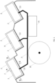
- the drawings depict a sample complex comprising three production lines 1, 2, 3, each on dedicated GBS 4, 5, 6 ( Fig. 1 ).
- Each production line 1 (2, 3) together with its respective GBS 4 (5, 6) is a prefabricated product fabricated at a specialized enterprise and then towed afloat to its installation site.
- Production line 1 (2) on GBS 4 (5) may have jetty 7 (8) to offload the products into tankers ( Fig. 2 ).
- GBS 4-6 are installed near specialized quaysides on dedicated underbase foundations 22 on the seabed ( Fig. 3 , 4 ).
- Production lines 1-3 on GBS 4-6 are interconnected by piping and cabling installed on overpasses 9 enabling the integration of production lines 1-3 into a single production complex.
- Each GBS is also connected to a shore with overpasses and bridges enabling the installation of respective piping and cabling to the shore without resorting to underwater pipelines and/or long overwater overpasses, as well as ease of access to the production complex and swift personnel evacuation.
- the short distance to the shore enables a simpler and cheaper integration with onshore facilities, including the hydrocarbon field, from which the feedstock is supplied to the production complex.
- Each production line 1-3 is a topside (modularized process equipment) on GBS 4-6 ( Figs. 2 , 3 and 4 ).
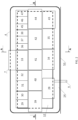
- the main process installations, in which the gas treatment and liquefaction process sequence is completed are ( Figs. 2 ): inlet facilities installation 28, including raw gas reception and treatment installations and a gas condensate stabilization installation, gas dehydration installation 29 and mercury removal installation 30, WFLH extraction installation 31 and fractionation installation 32, gas liquefaction installation 33, mixed refrigerant compressors installations 34 and 35, boil-off gas compressors installation 36, fuel gas installation 37, and heating medium system installation 38.
- the main process installations on either side of a GBS, as well as power plant 43, emergency diesel generators 44, nitrogen system installation 45, air compressors installations 46 and air dryers installations 47 have pipeline, cable tray and bridge connection via interconnecting modules 39-42.
- GBS 4-6 are three-dimensional structures made from reinforced concrete, which function is a storage for extracted and processed raw gas, as well as for auxiliary substances and materials. They underlie the topsides (production lines 1-3) and are designed to be installed on seabed of a water body with the help of their own weight.
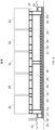
- GBS central part 12 is a rectangular prism with top slab 13 ( Figs. 3 and 4 ).
- the GBS On sides of central part 12 along its perimeter, the GBS has protruding part 14 with vertical external walls. GBS central part 12 and protruding part 14 share base slab 15, and protruding part 14 is lower than central part 12.
- GBS central part 12 is broken down into compartments with vertical longitudinal and transverse walls 16. Some of the compartments, e. g. compartments 17 and 18, are used for product (LNG and SGC) storage, while other compartments, e. g. compartments 19, 20 and 21, are used for ballast water.
- GBS protruding part 14 is broken down with vertical walls that are perpendicular to its external walls into compartments 20 along the GBS perimeter, which are also included in the ballast system.
- GBS top slab 13 has reinforced-concrete supports 24, on which the topside modules are installed.
- GBS 4-6 can stay afloat during water transportation to the site of the integrated production complex and can withstand ice impact in ice conditions. Changing the condition of GBS 4-6 from floating to stationary at the site of installation on the foundation 22 is ensured by flooding ballast compartments 19, 20, 21 with water.
- seabed reinforcement 23 such as gabions or other similar devices may be placed on the water bed around GBS 4-6 ( Fig.3 ).
- Each process production line for the liquefaction of natural gas with the use of mixed refrigerant contains inlet facilities installation 28 which includes equipment for receipt and treatment of raw gas, as well as gas condensate stabilization.
- Raw gas and condensate from the field are piped via overpass 9 to inlet facilities installation 28, in which raw gas reception, pressure control, liquid condensate (hydrocarbons and water) separation, carbon dioxide, hydrogen sulphide, methanol, and other impurities removal from the raw gas, and gas condensate stabilization occur.
- Stabilized gas condensate is sent to a storage tank with the capacity of approx. 75,000 m 3 ( Fig. 3 ).
- At least one concrete compartment 18 with the dimensions of 135 x 30 x 30 m is used as an SGC storage tank, the external structures of which act as a protective barrier.
- "Wet" storage involving an underlying water layer is used for SGC storage.
- the bottom layer of the stored product around 1 m in thickness is considered a mixing zone ensuring guaranteed separation of water and the stored product during loading operations.
- Compartment 18 is slightly pressurized (from the atmospheric pressure level) using a nitrogen cushion in the upper part of the compartment to prevent air penetration to the compartment and prevent any flammable and explosive gas mixtures with hydrocarbon vapors from forming.
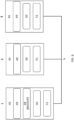
- SGC storage and offloading system ( Fig. 5 ) is common for the whole production complex, condensate may be pumped between at least two production lines through onshore pipelines, making it possible not to have SGC storage tank(s) in each GBS. If a complex comprises two GBS, SGC storage tanks may be located either in one of them or in both of them. If a complex consists of at least three GBS, said SGC storage tanks shall be placed in at least two GBS, and in this example only in GBS 4 and 5, where SGC is sent for storage also from the third production line 3 which does not have condensate storage tanks.
- Treated raw gas is sent to dehydration installation 29 and mercury removal installation 30 sequentially, where mercury, moisture, and remaining methanol are removed from the raw gas before it is sent to wide fraction of light hydrocarbons (WFLH) extraction installation 31.
- WFLH extraction installation 31 ethane, propane, butane, and NGL fractions are extracted from the treated gas before it is sent for liquefaction.
- At least one production line has WFLH fractionation installation 32.
- the ethane, propane, and butane produced at said installation are used for the purposes of mixed refrigerant components replenishment.
- Mixed refrigerant components replenishment system 48 is common for the whole complex.
- Refrigerant components may be pumped between the production lines through onshore pipelines. If a complex has two GBS and two production lines, the fractionation installation may be placed on either of the production lines or on both of them. If a complex consists of at least three production lines, it will suffice to place fractionation installations on at least two of them. In this example fractionation installations are installed on the first and second production lines 1 and 2 ( Fig. 6 ), where hydrocarbons extracted from gas are fractionated resulting in production of ethane, propane, and butanes fractions. Remaining stabilized heavy hydrocarbons are sent to SGC storage tanks - compartments 18.
- each mixed refrigerant component used for mixed refrigerant components replenishment at all three production lines 1-3, including at the production line 3 which does not have a fractionation installation and mixed refrigerant components storage tanks ( Fig. 6 ).
- the WFLH extracted at the third GBS 6 is returned to the flow of treated gas to the liquefaction installation or sent to WFLH fractionation installations installed at GBS 4 or 5. If a complex has two GBS, tanks for each mixed refrigerant component may be located in one or two GBS which have fractionation installation(s).
- each mixed refrigerant component In case of at least three GBS, having fractionation installations and tanks for each mixed refrigerant component at least in two production lines (1 and 2) allows to ensure duplication of this critically important equipment. All tanks 27 for each mixed refrigerant component have pipeline connections to refrigerant treatment and compressions systems of each production line to form single mixed refrigerant components replenishment system 48.
- Treated gas is sent to liquefaction installation 33 where three coil-wound heat exchangers are installed one after another, which are used to cool the gas with subsequent throttling and generation of liquefied fraction (LNG) and boil-off gas.
- Three mixed refrigerants with different composition which are mixtures of nitrogen, methane, ethane, propane, and butane, are used for gas cooling in the heat exchangers.
- the liquefied gas is sent to LNG storage tanks 25 accommodated inside each GBS 4-6.
- LNG storage tanks 25 have a pipeline interconnection to form a single LNG storage and offloading system.
- the LNG storage and offloading system ( Fig. 7 , 10 ) is common for the whole production complex, LNG may be pumped between tanks 25 in various GBS through onshore pipelines, allowing to use the total tank capacity to the maximum.
- Each GBS 4-6 accommodates at least one, or preferably two, tanks 25 for storage of LNG with capacity of 115,000 m 3 each.
- the total capacity of tanks 25 within the production complex amounts to approximately 690,000 m 3 .
- Membrane tanks are used for LNG storage.
- tank 25 consisting of a steel membrane made of stainless steel or invar (Fe-Ni alloy) separated from concrete structure by an insulation layer is installed inside concrete compartment 17 ( Figs 3 , 4 ).
- the insulation layer is placed directly on top slab 13, intermediate slab 26 and GBS walls 16, transferring the loads from tank 25 and its LNG content to the above-mentioned enclosing structures.
- the GBS slabs and walls thus serve as support structures for membrane tanks 25, with which they are integrated into a single structure.
- the bottom and the side surfaces of membrane tanks 25 have a secondary barrier being an additional membrane installed inside the insulation layer.
- Tanks for storage of ethane which is a mixed refrigerant component, have similar membrane structure but smaller capacity.
- GBS 4 and 5 each have one ethane tank with capacity of approximately 1,200 m 3 each ( Figs. 3 and 6 ).
- Self-supported tanks installed in GBS 4 and 5 compartments are used for other mixed refrigerant components - butane and propane.
- Said two GBS 4 and 5 each has one tank for storage of butane with the capacity of 280 m 3 each, and one tank for the storage of propane with capacity of 280 m 3 each ( Figs. 3 and 6 ).
- Tanks 27 for each mixed refrigerant component are located within a GBS as close as possible to the relevant process installations where these components are used, allowing to optimize the lengths and masses of pipelines, electrical heat tracing, and insulation.
- Refrigerant is treated and compressed at mixed refrigerant compressor installations 34 and 35 ( Fig. 2 ).
- Each of the three mixed refrigerant loops has two parallel strings, A and B, in the form of two separate installations with the capacity of 50% of the full capacity. This allows the production complex to work at 50% capacity even in case of shutdown of half of compressor installations.
- Each installation has two compressors on one shaft and on one frame. Each such pair of compressors is driven by one gas turbine drive, which reduces the number of gas turbine drives. All drives have the same capacity and are completely unified, which simplifies their operation and repairs.
- Ethane, propane, and butane extracted from WFLH at fractionation installations 32 and stored in tanks 27 for replenishment at GBS 1 and 2 are used to produce the refrigerant. Methane replenishment is done using treated raw gas and boil-off gas. Nitrogen for refrigerant replenishment is produced at comprehensive nitrogen system installation 45, which includes air separation installations 49 with air purification and dehydration systems, liquid nitrogen storage tanks 50, and liquid nitrogen vaporizers 51 ( Fig. 8 ).
- the production line 1 accommodates comprehensive air separation installations 49 in the 2x100% configuration (one installation in operation, one installation on stand-by), while production lines 2 and 3 are equipped with air separation installations 49 in the 1x100% configuration.
- Nitrogen production redundancy for the whole production complex is ensured by production line 1 and the ability to pump nitrogen between production lines. Besides mixed refrigerant replenishment, nitrogen is used to create inert medium and gas cushions, purging, compressor dry gas seals, and as back-up source of purge gas.
- Boil-off gas generated in liquefaction installation 33, LNG storage tanks 25, and also in the gas carrier's cargo tanks during offloading is sent to boil-off gas compressors installation 36 for boil-off gas compression and distribution.
- Boil-off gas is partially used for the treatment at fuel gas installation 37, which is primarily consumed by gas turbines in power plant and mixed refrigerant compressors installations.
- Power supply system is common for the whole production complex ( Fig. 9 ).
- the system is based on gas turbine power plants 43 within each production line 1-3.
- Each power plant 43 within the production lines 1 and 2 has three gas turbine generators 52 (GTG), including two in operation and one on stand-by, while production line 3 has two GTGs 52.
- GTG 52 of the power plant and the turbine drives of mixed refrigerant compressors use unified gas turbines, which makes it easier and cheaper to operate and service the equipment.
- the gas turbines are equipped with installations to recover waste heat to be used to heat up the heating medium in heating medium system installation 38.
- Emergency diesel generators 44 serve as a standby power source. Since power plants 43 across the three production lines are incorporated into a single power supply system with the help of cables running through overpass 9, N+2 power generation sparing arrangement is enabled.
- a similar sparing principle is used for the air compressors and air dryers, for which the air supply systems across the three production lines are interconnected.
- air compressors installations 46 are installed in a 3 x 50% arrangement (two in operation, one on standby), whereas air compressor installations 46 of production line 3 are installed in a 2 x 50% arrangement ( Fig. 10 ).
- the sparing of air compressors installations of production line 3 is ensured by backup capacities of production lines 1 and 2.
- Air dryers installations 47 are installed on each production line, with two of them also having backup air dryers installations. On production lines 1 and 2, these installations are installed in a 3 x 50% arrangement (two in operation, one on standby), whereas the air dryers installations are installed on the production line 3 in a 2 x 50% arrangement ( Fig. 11 ). The sparing of air dryers installation 47 on production line 3 is ensured by backup air dryers installations 47 of production lines 1 and 2. Dry air is used to build up pressure in the gas turbine engines and to provide barrier air for the couplings of the gas turbine drives of the mixed refrigerant compressors.
- LNG is offloaded into tankers for transporting liquefied gas via jetties 7 and 8, which are only installed on certain production lines, for instance on production lines 1 and 2 and GBS 4 and 5 ( Fig. 1 ). Same jetties 7, 8 are used for SGC offloading. Products of production line 3 are offloaded at the jetties of the production lines 1 and 2 via the LNG and SGC storage and offloading systems.
- Offloading jetties 7, 8 are structurally integrated into GBS 4, 5 and the topside. Fenders and a technological platform with loading arms as well as other marine and process equipment enabling LNG and SGC offloading are installed on protruding part 14 on the berthing side of the GBS. Mooring equipment for tanker berthing is installed on the GBS berthing side. The water area near jetty 7, 8 may have seabed reinforcement 23 protecting the bottom soil from scouring by ships propellers ( Fig. 3 ).
- Production lines 1-3 are interconnected by cables and pipelines running on overpass 9 and the quayside. Same overpass 9 is used to connect the production complex to the field and other onshore facilities.
Landscapes
- Engineering & Computer Science (AREA)
- Physics & Mathematics (AREA)
- Mechanical Engineering (AREA)
- Thermal Sciences (AREA)
- General Engineering & Computer Science (AREA)
- Chemical & Material Sciences (AREA)
- Chemical Kinetics & Catalysis (AREA)
- General Chemical & Material Sciences (AREA)
- Oil, Petroleum & Natural Gas (AREA)
- Ocean & Marine Engineering (AREA)
- Filling Or Discharging Of Gas Storage Vessels (AREA)
- Separation By Low-Temperature Treatments (AREA)
Abstract
Description
- The invention pertains to production facilities and can be used for development of near-shore and offshore integrated liquefied natural gas (LNG) production complexes on gravity-based structures.
- There are several types of near-shore and offshore hydrocarbon processing plants, for instance natural gas liquefaction plants (LNG plants) on floating and gravity-based substructures.
- A common design is an LNG production complex, which is a floating natural gas production, treatment, liquefaction, LNG storage and offloading installation. Floating installations for production, storage, and offloading of LNG (FLNG) are used of offshore gas field developments and is installed directly at the offshore field using anchoring and/or mooring. Such floating installations are not operated in offshore locations with heavy ice conditions since their reliable positioning necessary to connect to valves on underwater pipes is impossible due to the drifting ice, therefore floating LNG plant applications are limited to offshore field development in ice-free seas. Furthermore, production capacity of floating installations is limited by their size, they can only accommodate a single produxtion line requiring the full set of primary and auxiliary equipment to support the line operation and at the same time limiting the critical equipment sparing options.
- One example of an LNG plant on a gravity-based structure (GBS) is a near-shore LNG production, storage, and offloading plant (
US 2016/0231050 A1, publication date: 2016/08/11 ) with liquefaction equipment installed on a top deck of the gravity-based structure, and the plant capacity may be expanded by installing additional equipment in pre-existing areas of the GBS top slab and/or by using additional process installations mounted on their dedicated base structures resting on a seabed or on a shore near the GBS, which accommodates most of the process equipment. This design features the following disadvantages. - 1. Large-size GBS to accommodate additional equipment.
- 2. Equipment belonging to the same production line is distributed across several locations, meaning longer pipe and cable runs and a more complicated plant operation.
- 3. Equipment duplication in case of capacity expansion.
- 4. Equipment of individual production lines cannot be used for sparing purposes of the production complex as a whole.
- A complex design, which is the closest to the proposed one, features an LNG plant on three gravity-based structures (GBS), each accommodating an individual production line (Arctic LNG 2 project. Environmental, social and health impact assessment. Non-technical summary. Prepared by Ramboll CIS. August 2020, pages 10-12. http://arcticspg.ru/%D0%A0%D0%B5%D0%B7%D1%8E%D0%BC%D0%B 5%20%D0%BD%D0%B5%D1%82%D0%B5%D1%85%D0%BD%D0%B8 %D1%87%D0%B5%D1%81%D0%BA%D0%BE%D0%B3%D0%BE%20% D1%85%D0%B0%D1%80%D0%B0%D0%BA%D1%82%D0%B5%D1%80 %D0%B0/Arctic%20LNG%202%20NTS%20v3 final%20report RUS_clean .pdf). The LNG plant comprises three gravity-based structures (GBS), each accommodating a natural gas liquefaction line relying on a mixed refrigerant, including gas condensate stabilization installations, a mercury removal installation, acid gas removal and dehydration installations, wide fraction of light hydrocarbons (WFLH) extraction installations, and a liquefaction installation and a fractionation installation for generation of mixed refrigerant components from WFLH, each GBS having at least one LNG storage tank and at least one stable gas condensate (SGC) storage tank, and each GBS also having at least one tank for each mixed refrigerant component as well as an LNG and SGC offloading jetty.
- The disadvantage of this facility is that process equipment is triplicated across the three production lines as well as that there is no possibility to use an individual line equipment for sparing of the production complex equipment as a whole.
- The proposed invention offers a solution for the technical problem of equipment duplication in LNG production complexes comprising two or more production lines, each accommodated on a dedicated GBS.
- Technical result accomplished by the invention is enabling the avoidance of excess equipment duplication by developing shared-use technical systems for the entire complex. Certain design options for the complex also enable the necessary sparing of critical systems by using equipment on a GBS to sustain the operation of production lines accommodated on other GBS.
- The technical result is delivered as a liquefied natural gas (LNG) production complex comprising at least two GBS, each accommodating a natural gas liquefaction production line using a mixed refrigerant, including raw gas reception and treatment installations, a gas condensate stabilization installation, gas dehydration and mercury removal installations, a wide fraction of light hydrocarbons (WFLH) extraction installation, a refrigerants treatment and compression system, and a liquefaction installation, with at least one GBS production line incorporating a fractionation installation to generate mixed refrigerant components from WFLH, and at least one respective GBS having at least one storage tank for each mixed refrigerant component. Each GBS has at least one LNG storage tank. At least one GBS has at least one stable gas condensate (SGC) storage tank. At least one GBS has a jetty for offloading LNG and SGC into tankers.
- In accordance with the invention, at least one of each tank for each mixed refrigerant component has pipeline connections to the refrigerant treatment and compressions systems of each production line to form a single mixed refrigerant components replenishment system, at least one SGC storage tank has a pipeline connection to condensate stabilization installations of all the production lines to form a single SGC storage and offloading system, and the LNG storage tanks have a pipeline interconnection to form a single LNG storage and offloading system.
- There are following design options for the complex.
- The complex may comprise two GBS, with the said fractionation installation being installed on one, or each of the two production lines, and at least one said tank for each mixed refrigerant component being installed in one, or each of the two GBS.
- The complex may comprise at least three GBS, with the said fractionation installations being installed on at least two production lines, and at least one of each said tank for each mixed refrigerant component being installed in at least two respective GBS.
- For a two-GBS complex, at least one said SGC storage tank is installed in one, or each, of the two GBS.
- For a three or more GBS complex, at least one SGC storage tank is installed in at least two GBS.
- Furthermore, for a three or more GBS complex, the jetties for offloading LNG and SGC are available at least on two GBS.
- Each production line may comprise a nitrogen system, including an air separation installation, a nitrogen storage tank and a nitrogen vaporizer, with one of the production lines also having a backup air separation installation, and the nitrogen systems having a pipeline interconnection to form a single nitrogen supply system.
- Each production line may comprise air compressor installations, with two of the production lines having a backup air compressors installation, and the air compressors installations having a pipeline interconnection to form a single compressed air supply system.
- Each production line may comprise an air dryer installation, with two of the production lines having a backup air dryers installation, and the air dryers installations having a pipeline interconnection to form a single dry air system.
- It is advisable that each GBS has a power plant, with all the power plants having a cable interconnection to form a single power supply system, each power plant having gas turbine generators (GTGs), and two of the power plants each having a backup GTG.
-
-
Fig. 1 shows a scheme of the production complex on GBS. -
Fig. 2 shows a scheme of the GBS production line, view from above. -
Fig. 3 shows the transverse section A-A forFig. 1 . -
Fig. 4 shows the longitudinal section B-B forFig. 1 . -
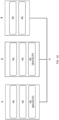
Fig. 5 shows a scheme of the SGC storage and offloading system -
Fig. 6 shows a scheme of a WFLH fractionation and mixed refrigerant components replenishment system. -
Fig. 7 shows a scheme of a LNG storage and offloading system. -
Fig. 8 shows a scheme of the nitrogen system. -
Fig. 9 shows a scheme of the power supply system. -
Fig. 10 shows a scheme of the air compressors installations. -
Fig. 11 shows a scheme of the air dryers installations. - The liquefied natural gas (LNG) production complex on gravity-based structures (GBS) is a combination of process, engineering and auxiliary equipment for production, storage and offloading of LNG and SGC. The complex may comprise two or more production lines on gravity-based structures (GBS).
- The drawings depict a sample complex comprising three
production lines dedicated GBS Fig. 1 ). Each production line 1 (2, 3) together with its respective GBS 4 (5, 6) is a prefabricated product fabricated at a specialized enterprise and then towed afloat to its installation site. Production line 1 (2) on GBS 4 (5) may have jetty 7 (8) to offload the products into tankers (Fig. 2 ). At the site, GBS 4-6 are installed near specialized quaysides ondedicated underbase foundations 22 on the seabed (Fig. 3 ,4 ). Production lines 1-3 on GBS 4-6 are interconnected by piping and cabling installed onoverpasses 9 enabling the integration of production lines 1-3 into a single production complex. Each GBS is also connected to a shore with overpasses and bridges enabling the installation of respective piping and cabling to the shore without resorting to underwater pipelines and/or long overwater overpasses, as well as ease of access to the production complex and swift personnel evacuation. The short distance to the shore enables a simpler and cheaper integration with onshore facilities, including the hydrocarbon field, from which the feedstock is supplied to the production complex. - On the shore near production lines 1-3, high-
pressure flare 10 andgeneral economies 11 are installed to be shared by the entire complex (Fig. 1 ). - Each production line 1-3 is a topside (modularized process equipment) on GBS 4-6 (
Figs. 2 ,3 and4 ). The main process installations, in which the gas treatment and liquefaction process sequence is completed are (Figs. 2 ):inlet facilities installation 28, including raw gas reception and treatment installations and a gas condensate stabilization installation,gas dehydration installation 29 andmercury removal installation 30,WFLH extraction installation 31 andfractionation installation 32,gas liquefaction installation 33, mixedrefrigerant compressors installations gas compressors installation 36,fuel gas installation 37, and heatingmedium system installation 38. - The main process installations on either side of a GBS, as well as
power plant 43,emergency diesel generators 44,nitrogen system installation 45,air compressors installations 46 andair dryers installations 47 have pipeline, cable tray and bridge connection via interconnecting modules 39-42. - GBS 4-6 are three-dimensional structures made from reinforced concrete, which function is a storage for extracted and processed raw gas, as well as for auxiliary substances and materials. They underlie the topsides (production lines 1-3) and are designed to be installed on seabed of a water body with the help of their own weight. GBS
central part 12 is a rectangular prism with top slab 13 (Figs. 3 and4 ). - On sides of
central part 12 along its perimeter, the GBS has protrudingpart 14 with vertical external walls. GBScentral part 12 and protrudingpart 14share base slab 15, and protrudingpart 14 is lower thancentral part 12. - GBS
central part 12 is broken down into compartments with vertical longitudinal andtransverse walls 16. Some of the compartments, e. g. compartments 17 and 18, are used for product (LNG and SGC) storage, while other compartments, e. g. compartments 19, 20 and 21, are used for ballast water.GBS protruding part 14 is broken down with vertical walls that are perpendicular to its external walls intocompartments 20 along the GBS perimeter, which are also included in the ballast system. -
GBS top slab 13 has reinforced-concrete supports 24, on which the topside modules are installed. - GBS 4-6 can stay afloat during water transportation to the site of the integrated production complex and can withstand ice impact in ice conditions. Changing the condition of GBS 4-6 from floating to stationary at the site of installation on the
foundation 22 is ensured by flooding ballast compartments 19, 20, 21 with water. - To prevent scouring of the bed under GBS 4-6 and the bed of the water body,
seabed reinforcement 23 such as gabions or other similar devices may be placed on the water bed around GBS 4-6 (Fig.3 ). - The technological process of the GBS LNG production complex has no fundamental differences from mixed refrigerant-based process technologies, which are used at onshore plants. Each process production line for the liquefaction of natural gas with the use of mixed refrigerant contains
inlet facilities installation 28 which includes equipment for receipt and treatment of raw gas, as well as gas condensate stabilization. Raw gas and condensate from the field are piped viaoverpass 9 toinlet facilities installation 28, in which raw gas reception, pressure control, liquid condensate (hydrocarbons and water) separation, carbon dioxide, hydrogen sulphide, methanol, and other impurities removal from the raw gas, and gas condensate stabilization occur. - Stabilized gas condensate (SGC) is sent to a storage tank with the capacity of approx. 75,000 m3 (
Fig. 3 ). At least oneconcrete compartment 18 with the dimensions of 135 x 30 x 30 m is used as an SGC storage tank, the external structures of which act as a protective barrier. "Wet" storage involving an underlying water layer is used for SGC storage. In this case, the bottom layer of the stored product around 1 m in thickness is considered a mixing zone ensuring guaranteed separation of water and the stored product during loading operations.Compartment 18 is slightly pressurized (from the atmospheric pressure level) using a nitrogen cushion in the upper part of the compartment to prevent air penetration to the compartment and prevent any flammable and explosive gas mixtures with hydrocarbon vapors from forming. - SGC storage and offloading system (
Fig. 5 ) is common for the whole production complex, condensate may be pumped between at least two production lines through onshore pipelines, making it possible not to have SGC storage tank(s) in each GBS. If a complex comprises two GBS, SGC storage tanks may be located either in one of them or in both of them. If a complex consists of at least three GBS, said SGC storage tanks shall be placed in at least two GBS, and in this example only inGBS third production line 3 which does not have condensate storage tanks. - Treated raw gas is sent to
dehydration installation 29 andmercury removal installation 30 sequentially, where mercury, moisture, and remaining methanol are removed from the raw gas before it is sent to wide fraction of light hydrocarbons (WFLH)extraction installation 31. AtWFLH extraction installation 31, ethane, propane, butane, and NGL fractions are extracted from the treated gas before it is sent for liquefaction. - At least one production line has
WFLH fractionation installation 32. The ethane, propane, and butane produced at said installation are used for the purposes of mixed refrigerant components replenishment. Mixed refrigerantcomponents replenishment system 48 is common for the whole complex. Refrigerant components may be pumped between the production lines through onshore pipelines. If a complex has two GBS and two production lines, the fractionation installation may be placed on either of the production lines or on both of them. If a complex consists of at least three production lines, it will suffice to place fractionation installations on at least two of them. In this example fractionation installations are installed on the first andsecond production lines 1 and 2 (Fig. 6 ), where hydrocarbons extracted from gas are fractionated resulting in production of ethane, propane, and butanes fractions. Remaining stabilized heavy hydrocarbons are sent to SGC storage tanks - compartments 18. - To store mixed refrigerant components in at least one GBS in case of at least three GBS - in at least two GBS, and in this example in the first and
second GBS separate tanks 27 are provided, at least one for each mixed refrigerant component, used for mixed refrigerant components replenishment at all three production lines 1-3, including at theproduction line 3 which does not have a fractionation installation and mixed refrigerant components storage tanks (Fig. 6 ). The WFLH extracted at thethird GBS 6 is returned to the flow of treated gas to the liquefaction installation or sent to WFLH fractionation installations installed atGBS tanks 27 for each mixed refrigerant component have pipeline connections to refrigerant treatment and compressions systems of each production line to form single mixed refrigerantcomponents replenishment system 48. - Treated gas is sent to
liquefaction installation 33 where three coil-wound heat exchangers are installed one after another, which are used to cool the gas with subsequent throttling and generation of liquefied fraction (LNG) and boil-off gas. Three mixed refrigerants with different composition, which are mixtures of nitrogen, methane, ethane, propane, and butane, are used for gas cooling in the heat exchangers. The liquefied gas is sent toLNG storage tanks 25 accommodated inside each GBS 4-6.LNG storage tanks 25 have a pipeline interconnection to form a single LNG storage and offloading system. The LNG storage and offloading system (Fig. 7 ,10 ) is common for the whole production complex, LNG may be pumped betweentanks 25 in various GBS through onshore pipelines, allowing to use the total tank capacity to the maximum. - Each GBS 4-6 accommodates at least one, or preferably two,
tanks 25 for storage of LNG with capacity of 115,000 m3 each. Thus, the total capacity oftanks 25 within the production complex amounts to approximately 690,000 m3. Membrane tanks are used for LNG storage. In this case,tank 25 consisting of a steel membrane made of stainless steel or invar (Fe-Ni alloy) separated from concrete structure by an insulation layer is installed inside concrete compartment 17 (Figs 3 ,4 ). The insulation layer is placed directly ontop slab 13,intermediate slab 26 andGBS walls 16, transferring the loads fromtank 25 and its LNG content to the above-mentioned enclosing structures. The GBS slabs and walls thus serve as support structures formembrane tanks 25, with which they are integrated into a single structure. To prevent any leaks, the bottom and the side surfaces ofmembrane tanks 25 have a secondary barrier being an additional membrane installed inside the insulation layer. - Tanks for storage of ethane, which is a mixed refrigerant component, have similar membrane structure but smaller capacity.
GBS Figs. 3 and6 ). - Self-supported tanks installed in
GBS GBS Figs. 3 and6 ). -
Tanks 27 for each mixed refrigerant component are located within a GBS as close as possible to the relevant process installations where these components are used, allowing to optimize the lengths and masses of pipelines, electrical heat tracing, and insulation. - Refrigerant is treated and compressed at mixed
refrigerant compressor installations 34 and 35 (Fig. 2 ). Each of the three mixed refrigerant loops has two parallel strings, A and B, in the form of two separate installations with the capacity of 50% of the full capacity. This allows the production complex to work at 50% capacity even in case of shutdown of half of compressor installations. - Each installation has two compressors on one shaft and on one frame. Each such pair of compressors is driven by one gas turbine drive, which reduces the number of gas turbine drives. All drives have the same capacity and are completely unified, which simplifies their operation and repairs.
- Ethane, propane, and butane extracted from WFLH at
fractionation installations 32 and stored intanks 27 for replenishment atGBS nitrogen system installation 45, which includesair separation installations 49 with air purification and dehydration systems, liquidnitrogen storage tanks 50, and liquid nitrogen vaporizers 51 (Fig. 8 ). Theproduction line 1 accommodates comprehensiveair separation installations 49 in the 2x100% configuration (one installation in operation, one installation on stand-by), whileproduction lines air separation installations 49 in the 1x100% configuration. Nitrogen production redundancy for the whole production complex is ensured byproduction line 1 and the ability to pump nitrogen between production lines. Besides mixed refrigerant replenishment, nitrogen is used to create inert medium and gas cushions, purging, compressor dry gas seals, and as back-up source of purge gas. - Boil-off gas generated in
liquefaction installation 33,LNG storage tanks 25, and also in the gas carrier's cargo tanks during offloading is sent to boil-offgas compressors installation 36 for boil-off gas compression and distribution. Boil-off gas is partially used for the treatment atfuel gas installation 37, which is primarily consumed by gas turbines in power plant and mixed refrigerant compressors installations. - Power supply system is common for the whole production complex (
Fig. 9 ). The system is based on gasturbine power plants 43 within each production line 1-3. Eachpower plant 43 within theproduction lines production line 3 has twoGTGs 52.GTG 52 of the power plant and the turbine drives of mixed refrigerant compressors use unified gas turbines, which makes it easier and cheaper to operate and service the equipment. The gas turbines are equipped with installations to recover waste heat to be used to heat up the heating medium in heatingmedium system installation 38. -
Emergency diesel generators 44 serve as a standby power source. Sincepower plants 43 across the three production lines are incorporated into a single power supply system with the help of cables running throughoverpass 9, N+2 power generation sparing arrangement is enabled. - A similar sparing principle is used for the air compressors and air dryers, for which the air supply systems across the three production lines are interconnected.
- On
production lines air compressors installations 46 are installed in a 3 x 50% arrangement (two in operation, one on standby), whereasair compressor installations 46 ofproduction line 3 are installed in a 2 x 50% arrangement (Fig. 10 ). The sparing of air compressors installations ofproduction line 3 is ensured by backup capacities ofproduction lines -
Air dryers installations 47 are installed on each production line, with two of them also having backup air dryers installations. Onproduction lines production line 3 in a 2 x 50% arrangement (Fig. 11 ). The sparing ofair dryers installation 47 onproduction line 3 is ensured by backupair dryers installations 47 ofproduction lines - LNG is offloaded into tankers for transporting liquefied gas via
jetties production lines GBS 4 and 5 (Fig. 1 ).Same jetties production line 3 are offloaded at the jetties of theproduction lines - Offloading
jetties GBS part 14 on the berthing side of the GBS. Mooring equipment for tanker berthing is installed on the GBS berthing side. The water area nearjetty seabed reinforcement 23 protecting the bottom soil from scouring by ships propellers (Fig. 3 ). - Production lines 1-3 are interconnected by cables and pipelines running on
overpass 9 and the quayside.Same overpass 9 is used to connect the production complex to the field and other onshore facilities. -
- 1. Production line (GBS topside)
- 2. Production line (GBS topside)
- 3. Production line (GBS topside)
- 4. GBS
- 5. GBS
- 6. GBS
- 7. Jetty for tankers
- 8. Jetty for tankers
- 9. Interconnecting overpass
- 10. High-pressure flare
- 11. Objects of general economy
- 12. GBS central part
- 13. Top slab of the GBS central part
- 14. GBS protruding part
- 15. GBS base slab
- 16. GBS vertical wall
- 17. LNG storage compartment
- 18. SGC storage compartment
- 19. Inner ballast compartments
- 20. Outer ballast compartments
- 21. Inner ballast compartments under the intermediate support slab of the LNG storage tank
- 22. GBS underbase foundation
- 23. Seabed reinforcement
- 24. Topside support
- 25. LNG storage tank
- 26. Support slab for LNG storage tank
- 27. Mixed refrigerant components storage tanks
- 28. Inlet facilities installation
- 29. Gas dehydration installation
- 30. Mercury removal installation
- 31. WFLH extraction installation
- 32. Fractionation installation
- 33. Gas liquefaction installation
- 34. Mixed refrigerant compressors installation (line A)
- 35. Mixed refrigerant compressors installation (line B)
- 36. Boil-off gas compressors installation
- 37. Fuel gas installation
- 38. Heating medium system installation
- 39. 1st interconnecting module
- 40. 2nd interconnecting module
- 41. 3rd interconnecting module
- 42. 4th interconnecting module
- 43. Power plant
- 44. Emergency diesel generators
- 45. Nitrogen systems installation
- 46. Air compressors installations
- 47. Air dryers installations
- 48. Mixed refrigerant components replenishment system
- 49. Air separation installation
- 50. Nitrogen storage tank
- 51. Nitrogen vaporizer
- 52. Gas turbine generator
- 53. Quayside
- 54. Seabed
- 55. Water level
Claims (10)
- A liquefied natural gas (LNG) production complex comprising at least two gravity-based structures (GBS), each accommodating a natural gas liquefaction production line using a mixed refrigerant, including raw gas reception and treatment installations, a gas condensate stabilization installation, gas dehydration and mercury removal installations, a wide fraction of light hydrocarbons (WFLH) extraction installation, a refrigerant treatment and compression system, and a liquefaction installation,with at least one GBS production line incorporating a fractionation installation to generate mixed refrigerant components from WFLH,with at least one respective GBS having at least one storage tank for each mixed refrigerant component,with each GBS having at least one LNG storage tank,with at least one GBS having at least one stable gas condensate (SGC) storage tank,with at least one GBS having a jetty for LNG and SGC offloading,characterized in thatat least one of each tank for each mixed refrigerant component has pipeline connections to the refrigerant treatment and compressions systems of each production line to form a single mixed refrigerant components replenishment system,at least one SGC storage tank has a pipeline connection to condensate stabilization installations of each production line to form a single SGC storage and offloading system,the LNG storage tanks have a pipeline interconnection to form a single LNG storage and offloading system.
- The complex according to claim 1, characterized in that it comprises two GBS, with the said fractionation installation being installed on one, or each, of the two production lines, and at least one tank for each mixed refrigerant component being installed in one, or each, of the two GBS.
- The complex according to claim 1, characterized in that it comprises at least three GBS, with the said fractionation installations being installed on at least two production lines, and at least one of each tank for each mixed refrigerant component being installed in at least two respective GBS.
- The complex according to claim 1, characterized in that it comprises two GBS, with at least one SGC storage tank being installed in one, or each of the two GBS.
- The complex according to claim 1, characterized in that it comprises at least three GBS, with at least one SGC storage tank being installed in at least two GBS.
- The complex according to claim 1, characterized in that it comprises at least three GBS, with the LNG and SGC offloading jetties being available at least on two GBS.
- The complex according to claim 1, characterized in that each production line comprises a nitrogen system, including an air separation installation, a nitrogen storage tank, and a nitrogen vaporizer, with one of the production lines also having a backup air separation installation, and the nitrogen systems having a pipeline interconnection to form a single nitrogen supply system.
- The complex according to claim 1, characterized in that each production line comprises air compressors installations, with two of the production lines having a backup air compressors installation, and the air compressors installations having a pipeline interconnection to form a single compressed air supply system.
- The complex according to claim 1, characterized in that each production line comprises an air dryers installation, with two of the production lines having a backup air dryers installation, and the air dryers installations having a pipeline interconnection to form a single dry air system.
- The complex according to claim 1, characterized in that each GBS accommodates a power plant, with all the power plants having a cable interconnection to form a single power supply system, each power plant having gas turbine generators (GTGs), and two of the power plants each having a backup GTG.
Applications Claiming Priority (2)
| Application Number | Priority Date | Filing Date | Title |
|---|---|---|---|
| RU2022116595A RU2778589C1 (en) | 2022-06-20 | Integrated complex for the production of liquefied natural gas (lng) on gravity type bases (gtb) | |
| PCT/RU2022/000332 WO2023249510A1 (en) | 2022-06-20 | 2022-11-09 | Liquefied natural gas production facility on gravity-based structures |
Publications (2)
| Publication Number | Publication Date |
|---|---|
| EP4541709A1 true EP4541709A1 (en) | 2025-04-23 |
| EP4541709A8 EP4541709A8 (en) | 2025-11-19 |
Family
ID=89380320
Family Applications (1)
| Application Number | Title | Priority Date | Filing Date |
|---|---|---|---|
| EP22948123.9A Pending EP4541709A1 (en) | 2022-06-20 | 2022-11-09 | Liquefied natural gas production facility on gravity-based structures |
Country Status (6)
| Country | Link |
|---|---|
| US (1) | US12656058B2 (en) |
| EP (1) | EP4541709A1 (en) |
| JP (1) | JP7872855B2 (en) |
| CN (1) | CN119365385A (en) |
| CA (1) | CA3248141A1 (en) |
| WO (1) | WO2023249510A1 (en) |
Families Citing this family (1)
| Publication number | Priority date | Publication date | Assignee | Title |
|---|---|---|---|---|
| RU2767575C1 (en) * | 2021-11-24 | 2022-03-17 | Публичное акционерное общество "НОВАТЭК" | Integrated complex for production of liquefied natural gas (lng) on gravity-based foundation (gbf) |
Family Cites Families (5)
| Publication number | Priority date | Publication date | Assignee | Title |
|---|---|---|---|---|
| AU2012207059B2 (en) * | 2007-09-28 | 2013-11-14 | Woodside Energy Limited | Linked LNG production facility |
| WO2014043736A1 (en) * | 2012-09-21 | 2014-03-27 | Woodside Energy Technologies Pty Ltd | Integrated storage/offloading facility for an lng production plant |
| EP2979049A4 (en) | 2013-03-27 | 2016-11-30 | Woodside Energy Technologies Pty Ltd | AIR-COOLED MODULAR LIQUEFIED GAS PRODUCTION PLANT |
| WO2015039169A1 (en) | 2013-09-21 | 2015-03-26 | Woodside Energy Technologies Pty Ltd | Expandable lng processing plant |
| US20200309450A1 (en) * | 2017-12-07 | 2020-10-01 | Shell Oil Company | Compact lng production train and method |
-
2022
- 2022-11-09 JP JP2024560887A patent/JP7872855B2/en active Active
- 2022-11-09 US US18/851,826 patent/US12656058B2/en active Active
- 2022-11-09 WO PCT/RU2022/000332 patent/WO2023249510A1/en not_active Ceased
- 2022-11-09 EP EP22948123.9A patent/EP4541709A1/en active Pending
- 2022-11-09 CN CN202280097120.0A patent/CN119365385A/en active Pending
- 2022-11-09 CA CA3248141A patent/CA3248141A1/en active Pending
Also Published As
| Publication number | Publication date |
|---|---|
| CA3248141A1 (en) | 2025-03-20 |
| CN119365385A (en) | 2025-01-24 |
| JP2025516127A (en) | 2025-05-27 |
| US20250198696A1 (en) | 2025-06-19 |
| WO2023249510A1 (en) | 2023-12-28 |
| EP4541709A8 (en) | 2025-11-19 |
| JP7872855B2 (en) | 2026-06-10 |
| US12656058B2 (en) | 2026-06-16 |
Similar Documents
| Publication | Publication Date | Title |
|---|---|---|
| AU2016259407B2 (en) | Floating LNG Plant | |
| US20020046547A1 (en) | Methods and apparatus for compressed gas | |
| US20160231050A1 (en) | Expandable lng processing plant | |
| US20250198696A1 (en) | Liquefied natural gas production facility on gravity-based structures | |
| EP4417754A1 (en) | Integrated production complex on a gravity-based structure (gbs) | |
| OA21782A (en) | Liquefied Natural Gas Production Facility On Gravity-Based Structures. | |
| RU2778589C1 (en) | Integrated complex for the production of liquefied natural gas (lng) on gravity type bases (gtb) | |
| US20250320678A1 (en) | Offshore production facility for producing, treating and refining raw gas | |
| EP4438815A1 (en) | Integrated liquefied natural gas (lng) production facility on a gravity-based structure (gbs) | |
| KR20240159433A (en) | Large LNG tank upper double deck block mounting method of nearshore floating liquefied natural gas facility | |
| OA21770A (en) | Integrated liquefied natural gas (LNG) production facility on a gravity-based structure (GBS). | |
| Nezamian et al. | Concept evaluation of concrete floating liquefied natural gas (FLNG) | |
| EP4667345A1 (en) | Selective positioning of a pump tower in a storage tank for liquified natural gas | |
| KR20240159515A (en) | Nearshore floating liquefied natural gas facility having cargo hold with constant width and height and design method | |
| KR20240159516A (en) | Nearshore floating liquefied natural gas facility having floater's own power supply device | |
| KR102694831B1 (en) | Marine structure with lng regasification system and manufacturing method there of | |
| OA21850A (en) | Offshore Production Facility For Producing, Treating And Refining Raw Gas. | |
| KR20240159431A (en) | Method and device for pre-determination of equipment specifications for manufacturing nearshore floating liquefied natural gas facility | |
| Gervois et al. | Offshore LNG Receiving Terminals: An Alternative To Onshore Terminal | |
| Gervois et al. | Floating LNG-A look at export and import terminals | |
| Varagka | ‘Regulatory coupling of large and small scale LNG terminals in the light of the newest European clean fuel energy strategy’ |
Legal Events
| Date | Code | Title | Description |
|---|---|---|---|
| STAA | Information on the status of an ep patent application or granted ep patent |
Free format text: STATUS: THE INTERNATIONAL PUBLICATION HAS BEEN MADE |
|
| PUAI | Public reference made under article 153(3) epc to a published international application that has entered the european phase |
Free format text: ORIGINAL CODE: 0009012 |
|
| STAA | Information on the status of an ep patent application or granted ep patent |
Free format text: STATUS: REQUEST FOR EXAMINATION WAS MADE |
|
| 17P | Request for examination filed |
Effective date: 20240920 |
|
| AK | Designated contracting states |
Kind code of ref document: A1 Designated state(s): AL AT BE BG CH CY CZ DE DK EE ES FI FR GB GR HR HU IE IS IT LI LT LU LV MC ME MK MT NL NO PL PT RO RS SE SI SK SM TR |
|
| DAX | Request for extension of the european patent (deleted) | ||
| RAV | Requested validation state of the european patent: fee paid |
Extension state: KH Effective date: 20240920 Extension state: MA Effective date: 20240920 Extension state: TN Effective date: 20240920 |
|
| RBV | Designated contracting states (corrected) |
Designated state(s): AL CH GB IS LI MC ME MK NO RS SM TR |
|
| REG | Reference to a national code |
Ref country code: DE Ref legal event code: R108 |