EP4541673A1 - Electric brake device - Google Patents
Electric brake device Download PDFInfo
- Publication number
- EP4541673A1 EP4541673A1 EP23823569.1A EP23823569A EP4541673A1 EP 4541673 A1 EP4541673 A1 EP 4541673A1 EP 23823569 A EP23823569 A EP 23823569A EP 4541673 A1 EP4541673 A1 EP 4541673A1
- Authority
- EP
- European Patent Office
- Prior art keywords
- braking torque
- motor
- relationship
- current
- brake device
- Prior art date
- Legal status (The legal status is an assumption and is not a legal conclusion. Google has not performed a legal analysis and makes no representation as to the accuracy of the status listed.)
- Pending
Links
Images


Classifications
-
- B—PERFORMING OPERATIONS; TRANSPORTING
- B60—VEHICLES IN GENERAL
- B60T—VEHICLE BRAKE CONTROL SYSTEMS OR PARTS THEREOF; BRAKE CONTROL SYSTEMS OR PARTS THEREOF, IN GENERAL; ARRANGEMENT OF BRAKING ELEMENTS ON VEHICLES IN GENERAL; PORTABLE DEVICES FOR PREVENTING UNWANTED MOVEMENT OF VEHICLES; VEHICLE MODIFICATIONS TO FACILITATE COOLING OF BRAKES
- B60T8/00—Arrangements for adjusting wheel-braking force to meet varying vehicular or ground-surface conditions, e.g. limiting or varying distribution of braking force
- B60T8/17—Using electrical or electronic regulation means to control braking
- B60T8/171—Detecting parameters used in the regulation; Measuring values used in the regulation
-
- B—PERFORMING OPERATIONS; TRANSPORTING
- B60—VEHICLES IN GENERAL
- B60T—VEHICLE BRAKE CONTROL SYSTEMS OR PARTS THEREOF; BRAKE CONTROL SYSTEMS OR PARTS THEREOF, IN GENERAL; ARRANGEMENT OF BRAKING ELEMENTS ON VEHICLES IN GENERAL; PORTABLE DEVICES FOR PREVENTING UNWANTED MOVEMENT OF VEHICLES; VEHICLE MODIFICATIONS TO FACILITATE COOLING OF BRAKES
- B60T8/00—Arrangements for adjusting wheel-braking force to meet varying vehicular or ground-surface conditions, e.g. limiting or varying distribution of braking force
- B60T8/17—Using electrical or electronic regulation means to control braking
- B60T8/172—Determining control parameters used in the regulation, e.g. by calculations involving measured or detected parameters
-
- B—PERFORMING OPERATIONS; TRANSPORTING
- B60—VEHICLES IN GENERAL
- B60T—VEHICLE BRAKE CONTROL SYSTEMS OR PARTS THEREOF; BRAKE CONTROL SYSTEMS OR PARTS THEREOF, IN GENERAL; ARRANGEMENT OF BRAKING ELEMENTS ON VEHICLES IN GENERAL; PORTABLE DEVICES FOR PREVENTING UNWANTED MOVEMENT OF VEHICLES; VEHICLE MODIFICATIONS TO FACILITATE COOLING OF BRAKES
- B60T1/00—Arrangements of braking elements, i.e. of those parts where braking effect occurs specially for vehicles
- B60T1/02—Arrangements of braking elements, i.e. of those parts where braking effect occurs specially for vehicles acting by retarding wheels
- B60T1/06—Arrangements of braking elements, i.e. of those parts where braking effect occurs specially for vehicles acting by retarding wheels acting otherwise than on tread, e.g. employing rim, drum, disc, or transmission or on double wheels
- B60T1/065—Arrangements of braking elements, i.e. of those parts where braking effect occurs specially for vehicles acting by retarding wheels acting otherwise than on tread, e.g. employing rim, drum, disc, or transmission or on double wheels employing disc
-
- B—PERFORMING OPERATIONS; TRANSPORTING
- B60—VEHICLES IN GENERAL
- B60T—VEHICLE BRAKE CONTROL SYSTEMS OR PARTS THEREOF; BRAKE CONTROL SYSTEMS OR PARTS THEREOF, IN GENERAL; ARRANGEMENT OF BRAKING ELEMENTS ON VEHICLES IN GENERAL; PORTABLE DEVICES FOR PREVENTING UNWANTED MOVEMENT OF VEHICLES; VEHICLE MODIFICATIONS TO FACILITATE COOLING OF BRAKES
- B60T13/00—Transmitting braking action from initiating means to ultimate brake actuator with power assistance or drive; Brake systems incorporating such transmitting means, e.g. air-pressure brake systems
- B60T13/74—Transmitting braking action from initiating means to ultimate brake actuator with power assistance or drive; Brake systems incorporating such transmitting means, e.g. air-pressure brake systems with electrical assistance or drive
-
- B—PERFORMING OPERATIONS; TRANSPORTING
- B60—VEHICLES IN GENERAL
- B60T—VEHICLE BRAKE CONTROL SYSTEMS OR PARTS THEREOF; BRAKE CONTROL SYSTEMS OR PARTS THEREOF, IN GENERAL; ARRANGEMENT OF BRAKING ELEMENTS ON VEHICLES IN GENERAL; PORTABLE DEVICES FOR PREVENTING UNWANTED MOVEMENT OF VEHICLES; VEHICLE MODIFICATIONS TO FACILITATE COOLING OF BRAKES
- B60T13/00—Transmitting braking action from initiating means to ultimate brake actuator with power assistance or drive; Brake systems incorporating such transmitting means, e.g. air-pressure brake systems
- B60T13/74—Transmitting braking action from initiating means to ultimate brake actuator with power assistance or drive; Brake systems incorporating such transmitting means, e.g. air-pressure brake systems with electrical assistance or drive
- B60T13/741—Transmitting braking action from initiating means to ultimate brake actuator with power assistance or drive; Brake systems incorporating such transmitting means, e.g. air-pressure brake systems with electrical assistance or drive acting on an ultimate actuator
-
- B—PERFORMING OPERATIONS; TRANSPORTING
- B60—VEHICLES IN GENERAL
- B60T—VEHICLE BRAKE CONTROL SYSTEMS OR PARTS THEREOF; BRAKE CONTROL SYSTEMS OR PARTS THEREOF, IN GENERAL; ARRANGEMENT OF BRAKING ELEMENTS ON VEHICLES IN GENERAL; PORTABLE DEVICES FOR PREVENTING UNWANTED MOVEMENT OF VEHICLES; VEHICLE MODIFICATIONS TO FACILITATE COOLING OF BRAKES
- B60T13/00—Transmitting braking action from initiating means to ultimate brake actuator with power assistance or drive; Brake systems incorporating such transmitting means, e.g. air-pressure brake systems
- B60T13/74—Transmitting braking action from initiating means to ultimate brake actuator with power assistance or drive; Brake systems incorporating such transmitting means, e.g. air-pressure brake systems with electrical assistance or drive
- B60T13/746—Transmitting braking action from initiating means to ultimate brake actuator with power assistance or drive; Brake systems incorporating such transmitting means, e.g. air-pressure brake systems with electrical assistance or drive and mechanical transmission of the braking action
-
- B—PERFORMING OPERATIONS; TRANSPORTING
- B60—VEHICLES IN GENERAL
- B60T—VEHICLE BRAKE CONTROL SYSTEMS OR PARTS THEREOF; BRAKE CONTROL SYSTEMS OR PARTS THEREOF, IN GENERAL; ARRANGEMENT OF BRAKING ELEMENTS ON VEHICLES IN GENERAL; PORTABLE DEVICES FOR PREVENTING UNWANTED MOVEMENT OF VEHICLES; VEHICLE MODIFICATIONS TO FACILITATE COOLING OF BRAKES
- B60T17/00—Component parts, details, or accessories of power brake systems not covered by groups B60T8/00, B60T13/00 or B60T15/00, or presenting other characteristic features
- B60T17/18—Safety devices; Monitoring
-
- F—MECHANICAL ENGINEERING; LIGHTING; HEATING; WEAPONS; BLASTING
- F16—ENGINEERING ELEMENTS AND UNITS; GENERAL MEASURES FOR PRODUCING AND MAINTAINING EFFECTIVE FUNCTIONING OF MACHINES OR INSTALLATIONS; THERMAL INSULATION IN GENERAL
- F16D—COUPLINGS FOR TRANSMITTING ROTATION; CLUTCHES; BRAKES
- F16D55/00—Brakes with substantially-radial braking surfaces pressed together in axial direction, e.g. disc brakes
- F16D55/02—Brakes with substantially-radial braking surfaces pressed together in axial direction, e.g. disc brakes with axially-movable discs or pads pressed against axially-located rotating members
- F16D55/22—Brakes with substantially-radial braking surfaces pressed together in axial direction, e.g. disc brakes with axially-movable discs or pads pressed against axially-located rotating members by clamping an axially-located rotating disc between movable braking members, e.g. movable brake discs or brake pads
- F16D55/224—Brakes with substantially-radial braking surfaces pressed together in axial direction, e.g. disc brakes with axially-movable discs or pads pressed against axially-located rotating members by clamping an axially-located rotating disc between movable braking members, e.g. movable brake discs or brake pads with a common actuating member for the braking members
- F16D55/225—Brakes with substantially-radial braking surfaces pressed together in axial direction, e.g. disc brakes with axially-movable discs or pads pressed against axially-located rotating members by clamping an axially-located rotating disc between movable braking members, e.g. movable brake discs or brake pads with a common actuating member for the braking members the braking members being brake pads
- F16D55/226—Brakes with substantially-radial braking surfaces pressed together in axial direction, e.g. disc brakes with axially-movable discs or pads pressed against axially-located rotating members by clamping an axially-located rotating disc between movable braking members, e.g. movable brake discs or brake pads with a common actuating member for the braking members the braking members being brake pads in which the common actuating member is moved axially, e.g. floating caliper disc brakes
-
- F—MECHANICAL ENGINEERING; LIGHTING; HEATING; WEAPONS; BLASTING
- F16—ENGINEERING ELEMENTS AND UNITS; GENERAL MEASURES FOR PRODUCING AND MAINTAINING EFFECTIVE FUNCTIONING OF MACHINES OR INSTALLATIONS; THERMAL INSULATION IN GENERAL
- F16D—COUPLINGS FOR TRANSMITTING ROTATION; CLUTCHES; BRAKES
- F16D65/00—Parts or details
- F16D65/14—Actuating mechanisms for brakes; Means for initiating operation at a predetermined position
- F16D65/16—Actuating mechanisms for brakes; Means for initiating operation at a predetermined position arranged in or on the brake
-
- F—MECHANICAL ENGINEERING; LIGHTING; HEATING; WEAPONS; BLASTING
- F16—ENGINEERING ELEMENTS AND UNITS; GENERAL MEASURES FOR PRODUCING AND MAINTAINING EFFECTIVE FUNCTIONING OF MACHINES OR INSTALLATIONS; THERMAL INSULATION IN GENERAL
- F16D—COUPLINGS FOR TRANSMITTING ROTATION; CLUTCHES; BRAKES
- F16D65/00—Parts or details
- F16D65/14—Actuating mechanisms for brakes; Means for initiating operation at a predetermined position
- F16D65/16—Actuating mechanisms for brakes; Means for initiating operation at a predetermined position arranged in or on the brake
- F16D65/18—Actuating mechanisms for brakes; Means for initiating operation at a predetermined position arranged in or on the brake adapted for drawing members together, e.g. for disc brakes
-
- F—MECHANICAL ENGINEERING; LIGHTING; HEATING; WEAPONS; BLASTING
- F16—ENGINEERING ELEMENTS AND UNITS; GENERAL MEASURES FOR PRODUCING AND MAINTAINING EFFECTIVE FUNCTIONING OF MACHINES OR INSTALLATIONS; THERMAL INSULATION IN GENERAL
- F16D—COUPLINGS FOR TRANSMITTING ROTATION; CLUTCHES; BRAKES
- F16D65/00—Parts or details
- F16D65/14—Actuating mechanisms for brakes; Means for initiating operation at a predetermined position
- F16D65/16—Actuating mechanisms for brakes; Means for initiating operation at a predetermined position arranged in or on the brake
- F16D65/18—Actuating mechanisms for brakes; Means for initiating operation at a predetermined position arranged in or on the brake adapted for drawing members together, e.g. for disc brakes
- F16D65/183—Actuating mechanisms for brakes; Means for initiating operation at a predetermined position arranged in or on the brake adapted for drawing members together, e.g. for disc brakes with force-transmitting members arranged side by side acting on a spot type force-applying member
-
- F—MECHANICAL ENGINEERING; LIGHTING; HEATING; WEAPONS; BLASTING
- F16—ENGINEERING ELEMENTS AND UNITS; GENERAL MEASURES FOR PRODUCING AND MAINTAINING EFFECTIVE FUNCTIONING OF MACHINES OR INSTALLATIONS; THERMAL INSULATION IN GENERAL
- F16D—COUPLINGS FOR TRANSMITTING ROTATION; CLUTCHES; BRAKES
- F16D66/00—Arrangements for monitoring working conditions, e.g. wear, temperature
-
- H—ELECTRICITY
- H02—GENERATION; CONVERSION OR DISTRIBUTION OF ELECTRIC POWER
- H02P—CONTROL OR REGULATION OF ELECTRIC MOTORS, ELECTRIC GENERATORS OR DYNAMO-ELECTRIC CONVERTERS; CONTROLLING TRANSFORMERS, REACTORS OR CHOKE COILS
- H02P3/00—Arrangements for stopping or slowing electric motors, generators, or dynamo-electric converters
- H02P3/02—Details of stopping control
- H02P3/04—Means for stopping or slowing by a separate brake, e.g. friction brake or eddy-current brake
-
- B—PERFORMING OPERATIONS; TRANSPORTING
- B60—VEHICLES IN GENERAL
- B60T—VEHICLE BRAKE CONTROL SYSTEMS OR PARTS THEREOF; BRAKE CONTROL SYSTEMS OR PARTS THEREOF, IN GENERAL; ARRANGEMENT OF BRAKING ELEMENTS ON VEHICLES IN GENERAL; PORTABLE DEVICES FOR PREVENTING UNWANTED MOVEMENT OF VEHICLES; VEHICLE MODIFICATIONS TO FACILITATE COOLING OF BRAKES
- B60T2210/00—Detection or estimation of road or environment conditions; Detection or estimation of road shapes
- B60T2210/30—Environment conditions or position therewithin
- B60T2210/36—Global Positioning System [GPS]
-
- B—PERFORMING OPERATIONS; TRANSPORTING
- B60—VEHICLES IN GENERAL
- B60T—VEHICLE BRAKE CONTROL SYSTEMS OR PARTS THEREOF; BRAKE CONTROL SYSTEMS OR PARTS THEREOF, IN GENERAL; ARRANGEMENT OF BRAKING ELEMENTS ON VEHICLES IN GENERAL; PORTABLE DEVICES FOR PREVENTING UNWANTED MOVEMENT OF VEHICLES; VEHICLE MODIFICATIONS TO FACILITATE COOLING OF BRAKES
- B60T2220/00—Monitoring, detecting driver behaviour; Signalling thereof; Counteracting thereof
- B60T2220/03—Driver counter-steering; Avoidance of conflicts with ESP control
-
- B—PERFORMING OPERATIONS; TRANSPORTING
- B60—VEHICLES IN GENERAL
- B60T—VEHICLE BRAKE CONTROL SYSTEMS OR PARTS THEREOF; BRAKE CONTROL SYSTEMS OR PARTS THEREOF, IN GENERAL; ARRANGEMENT OF BRAKING ELEMENTS ON VEHICLES IN GENERAL; PORTABLE DEVICES FOR PREVENTING UNWANTED MOVEMENT OF VEHICLES; VEHICLE MODIFICATIONS TO FACILITATE COOLING OF BRAKES
- B60T2240/00—Monitoring, detecting wheel/tyre behaviour; counteracting thereof
- B60T2240/02—Longitudinal grip
-
- B—PERFORMING OPERATIONS; TRANSPORTING
- B60—VEHICLES IN GENERAL
- B60T—VEHICLE BRAKE CONTROL SYSTEMS OR PARTS THEREOF; BRAKE CONTROL SYSTEMS OR PARTS THEREOF, IN GENERAL; ARRANGEMENT OF BRAKING ELEMENTS ON VEHICLES IN GENERAL; PORTABLE DEVICES FOR PREVENTING UNWANTED MOVEMENT OF VEHICLES; VEHICLE MODIFICATIONS TO FACILITATE COOLING OF BRAKES
- B60T2240/00—Monitoring, detecting wheel/tyre behaviour; counteracting thereof
- B60T2240/06—Wheel load; Wheel lift
-
- B—PERFORMING OPERATIONS; TRANSPORTING
- B60—VEHICLES IN GENERAL
- B60T—VEHICLE BRAKE CONTROL SYSTEMS OR PARTS THEREOF; BRAKE CONTROL SYSTEMS OR PARTS THEREOF, IN GENERAL; ARRANGEMENT OF BRAKING ELEMENTS ON VEHICLES IN GENERAL; PORTABLE DEVICES FOR PREVENTING UNWANTED MOVEMENT OF VEHICLES; VEHICLE MODIFICATIONS TO FACILITATE COOLING OF BRAKES
- B60T2250/00—Monitoring, detecting, estimating vehicle conditions
-
- B—PERFORMING OPERATIONS; TRANSPORTING
- B60—VEHICLES IN GENERAL
- B60T—VEHICLE BRAKE CONTROL SYSTEMS OR PARTS THEREOF; BRAKE CONTROL SYSTEMS OR PARTS THEREOF, IN GENERAL; ARRANGEMENT OF BRAKING ELEMENTS ON VEHICLES IN GENERAL; PORTABLE DEVICES FOR PREVENTING UNWANTED MOVEMENT OF VEHICLES; VEHICLE MODIFICATIONS TO FACILITATE COOLING OF BRAKES
- B60T2250/00—Monitoring, detecting, estimating vehicle conditions
- B60T2250/03—Vehicle yaw rate
-
- B—PERFORMING OPERATIONS; TRANSPORTING
- B60—VEHICLES IN GENERAL
- B60Y—INDEXING SCHEME RELATING TO ASPECTS CROSS-CUTTING VEHICLE TECHNOLOGY
- B60Y2400/00—Special features of vehicle units
- B60Y2400/81—Braking systems
-
- F—MECHANICAL ENGINEERING; LIGHTING; HEATING; WEAPONS; BLASTING
- F16—ENGINEERING ELEMENTS AND UNITS; GENERAL MEASURES FOR PRODUCING AND MAINTAINING EFFECTIVE FUNCTIONING OF MACHINES OR INSTALLATIONS; THERMAL INSULATION IN GENERAL
- F16D—COUPLINGS FOR TRANSMITTING ROTATION; CLUTCHES; BRAKES
- F16D66/00—Arrangements for monitoring working conditions, e.g. wear, temperature
- F16D2066/005—Force, torque, stress or strain
-
- F—MECHANICAL ENGINEERING; LIGHTING; HEATING; WEAPONS; BLASTING
- F16—ENGINEERING ELEMENTS AND UNITS; GENERAL MEASURES FOR PRODUCING AND MAINTAINING EFFECTIVE FUNCTIONING OF MACHINES OR INSTALLATIONS; THERMAL INSULATION IN GENERAL
- F16D—COUPLINGS FOR TRANSMITTING ROTATION; CLUTCHES; BRAKES
- F16D66/00—Arrangements for monitoring working conditions, e.g. wear, temperature
- F16D2066/006—Arrangements for monitoring working conditions, e.g. wear, temperature without direct measurement of the quantity monitored, e.g. wear or temperature calculated form force and duration of braking
-
- F—MECHANICAL ENGINEERING; LIGHTING; HEATING; WEAPONS; BLASTING
- F16—ENGINEERING ELEMENTS AND UNITS; GENERAL MEASURES FOR PRODUCING AND MAINTAINING EFFECTIVE FUNCTIONING OF MACHINES OR INSTALLATIONS; THERMAL INSULATION IN GENERAL
- F16D—COUPLINGS FOR TRANSMITTING ROTATION; CLUTCHES; BRAKES
- F16D2121/00—Type of actuator operation force
- F16D2121/18—Electric or magnetic
- F16D2121/24—Electric or magnetic using motors
-
- F—MECHANICAL ENGINEERING; LIGHTING; HEATING; WEAPONS; BLASTING
- F16—ENGINEERING ELEMENTS AND UNITS; GENERAL MEASURES FOR PRODUCING AND MAINTAINING EFFECTIVE FUNCTIONING OF MACHINES OR INSTALLATIONS; THERMAL INSULATION IN GENERAL
- F16D—COUPLINGS FOR TRANSMITTING ROTATION; CLUTCHES; BRAKES
- F16D2125/00—Components of actuators
- F16D2125/18—Mechanical mechanisms
- F16D2125/20—Mechanical mechanisms converting rotation to linear movement or vice versa
- F16D2125/34—Mechanical mechanisms converting rotation to linear movement or vice versa acting in the direction of the axis of rotation
- F16D2125/40—Screw-and-nut
Definitions
- the present invention relates to an electric brake device used to brake vehicles.
- An electric brake device enables more precise control over braking force by accurately estimating the braking force.
- a thrust sensor can be used to estimate the braking force and thereby improve the estimation accuracy, but the cost increases.
- patent literature 1 proposes the technology as a method to estimate braking force without using a thrust sensor.
- a driving force is applied to drive wheels while a braking force is applied to the wheels.
- the technology calibrates control parameters to drive the electric motor of a brake mechanism provided for the wheels based on a driving wheel driving force that exceeds the braking force.
- Patent Literature 1 International Publication WO2020/262278
- patent literature 1 needs to compare a braking force with a driving force when estimating the braking force and needs to generate the driving force and correct the control parameters.
- highly accurate sensors are required to acquire accurate driving force information, increasing costs.
- the drive wheels need to move especially to acquire accurate driving force information without the use of high-precision sensors, complicating the control.
- an electric brake device includes an electric motor, a straight-moving portion, a brake pad, and a motor control device.
- the straight-moving portion moves through rotations of the electric motor.
- the brake pad presses a disc rotor that rotates along with a wheel through a thrust generated by movement of the straight-moving portion.
- the motor control device controls the rotations of the electric motor.
- the motor control device includes a motor position-current relationship generation portion, a braking torque estimation portion, and a braking torque-position relationship generation portion.
- the motor position-current relationship generation portion acquires a relationship between rotational position and the current of the electric motor.
- the braking torque estimation portion estimates a braking torque pressing the brake pad based on the rotational positions of the electric motor at a predetermined timing.
- the braking torque-position relationship generation portion that acquires a relationship between rotational position and the braking torque of the electric motor based on information from the motor position-current relationship generation portion and the braking torque estimation portion.
- the motor control device controls rotations of the electric motor based on information from the braking torque-position relationship generation portion.
- the present invention can provide an electric brake device capable of accurate control at low cost.
- FIG. 1 is a schematic diagram of the electric brake device according to the first embodiment of the present invention.
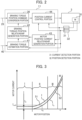
- FIG. 2 is a control block diagram of the electric brake device according to the first embodiment of the present invention.
- a vehicle such as a car includes four wheels such as right and left front wheels and right and left rear wheels.
- a brake device is provided for each wheel.
- the brake device 1 includes a housing 4, brake pads 5a and 5b (pressing members), a piston 6 (straight-moving portion), and an electric motor 8, for example.
- the housing 4 is supported to be floatable on a carrier (unshown) in the axial direction of a disc rotor 2 (rotating member).
- the carrier is secured to a non-rotating portion of the vehicle, the portion being positioned toward the inside of the vehicle away from the disc rotor 2.
- the brake pads 5a and 5b are located on both the right and left sides of the disc rotor 2.
- the piston 6 can straight move inside the housing 4.
- the electric motor 8 drives the piston 6.
- the electric motor 8 supplies thrust to the brake pads 5a and 5b via a rotation-to-linear conversion mechanism 10 and the piston 6.
- the brake pads 5a and 5b horizontally press the disc rotor 2, rotating along with the wheels, and provide braking force based on a clamping force (pad thrust).
- An output shaft of the electric motor 8 is connected to a reducer 9.
- An output shaft of the reducer 9 is connected to the rotation-to-linear conversion mechanism 10.
- the rotation-to-linear conversion mechanism 10 enables the piston 6 to move straight. The piston 6 straight moves based on the rotation of the electric motor 8.
- the disc rotor 2, the housing 4, the brake pads 5a and 5b, the piston 6, the electric motor 8, the reducer 9, and the rotation-to-linear conversion mechanism 10 configure a brake caliper 3.
- the rotation-to-linear conversion mechanism 10 and the piston 6 configure a straight-moving portion.
- the electric motor 8 connects to a motor control device 11 (controller) via an electric wire 12.
- the motor control device 11 controls rotations of the electric motor 8.
- the electric motor 8 and the motor control device 11 are separated from each other but may be integrated.
- the electric motor 8 includes a current detection portion 31 and a position detection portion 32 to detect applied currents.
- the motor control device 11 receives a control torque command 29 from a high-order control device (vehicle control ECU), for example.
- the motor control device 11 supplies an electric current command to the electric motor 8 based on a predetermined control program, for example, by using values detected in the current detection portion 31 and the position detection portion 32.
- a control signal line 21 and communication lines 22 and 23 are connected to the motor control device 11.
- the control signal line 21 supplies the motor control device 11 with a control command from a high-order control device such as a vehicle control ECU (Electronic Control Unit).
- the communication lines 22 and 23 are used to communicate with the high-order control device by supplying information other than control commands.
- the high-order control device and the motor control device 11 are provided separately but may be integrated into a control device.
- FIG. 2 illustrates a calculation method of the motor control device 11.
- the control torque command 29 is supplied from the vehicle control ECU via the control signal line 21.
- the control torque command 29 is converted into a position command value in a braking torque position command conversion portion 36 and is input to a position current control portion 44.
- the position current control portion 44 feeds back position information acquired from the position detection portion 32 based on a position command and current values of the electric motor 8 acquired by the current detection portion 31.
- An electric current command is then supplied to the electric motor 8 in the brake caliper 3.
- the braking torque position command conversion portion 36 converts the input control torque command into a motor position command and outputs based on the relationship between motor position and braking torque, the relationship being generated based on a braking torque-position relationship portion generation portion 42.
- the relationship is expressed as a braking torque position map that represents braking torque positions in a map form, for example.
- the braking torque-position relationship portion generation portion 42 is generated from the relationship between motor position and motor current generated by the motor position-current relationship generation portion 43 and outputs from the braking torque estimation portion 41.
- FIG. 3 is a diagram illustrating a relationship between motor current and motor position acquired by a motor position-current relationship generation portion according to the first embodiment of the present invention.
- the motor position-current relationship generation portion 43 acquires the rotational position and the current of the electric motor 8 and generates a relationship between the rotational position and the current of the electric motor 8.
- the electric motor 8 includes the current detection portion 31 and the position detection portion 32.
- a brake When a brake is operated during travel, for example, the brake pads 5a and 5b are pressed against the disc rotor 2 (applying operation) to simultaneously measure the motor position (rotational position of the electric motor 8) and the motor current (current of the electric motor 8). It is possible to acquire a relationship 51 between motor position x and motor current I as illustrated in FIG. 3 .
- motor current I usually contains a noise component. It is preferable to perform filtering by using a lowpass filter, for example.
- Motor current I contains a friction component (motor current I0 corresponding to the friction component) generated from a rotation-to-linear moving portion, for example.
- the friction component can be estimated from the current in a clearance area before the pad contact, for example.
- Motor position-current relationship 52 can be acquired by extracting effective motor current Ia to the exclusion of the friction component.
- state I shows a pad clearance that causes no braking force yet.
- Motor current I0 for the friction component is acquired in state I.
- state II is used to acquire characteristics in a region that generates a low thrust.
- State II allows the brake pads 5a and 5b to be in contact with the disc rotor 2 during normal travel to acquire a braking force. Normal travel provides characteristics of a high thrust range that occurs less frequently.
- operation III is performed to further increase the thrust. It is possible to acquire the relationship between motor position and motor current until the parking brake generates the thrust. Furthermore, the thrust may be temporarily increased to be larger than the thrust required for parking. The relationship between motor position and motor current can thereby be acquired in region IV corresponding to a higher thrust.
- the motor position-current relationship generation portion 43 acquires the relationship between the rotational position and the current of the electric motor 8 separately based on whether the vehicle travels or stops.
- the present embodiment can provide the relationship between motor position x and motor current I as non-linear characteristics in the entire range of braking force that needs to be generated up to a high thrust.
- the braking torque estimation portion 41 that estimates a braking torque to press the brake pads 5a and 5b.
- the braking torque can be estimated from vehicle conditions, for example.
- the braking torque is estimated during braking.
- longitudinal tire force Ftx causes a stop force by braking.
- Longitudinal tire force Ftx is expressed as a function of tire load Ftz.
- Longitudinal tire force Ftx can be approximated linearly in the range of small braking force and is proportional to slip ratio ⁇ as expressed by equation 1 below.
- Vb denotes the vehicle speed
- Vw denotes the value acquired by converting the wheel speed into the position of the center of gravity
- Kw denotes the proportionality coefficient determined by tire characteristics, for example.
- longitudinal force Ftx can be estimated by finding vehicle speed Vb, wheel speed Vw, tire load Ftz, and proportionality coefficient Kw.
- Longitudinal tire force Ftx includes braking/driving force Fd generated by the engine of an engine vehicle or the main motor of an electric vehicle. As seen from equation 3, braking/driving force Fd is subtracted from tire load Ftz to yield a value corresponding to the braking force due to the braking torque.
- Braking force Fb can be estimated by subtracting (excluding) the braking/driving force generated by the engine or motor from the estimated value.
- Fb Ftx ⁇ Fd
- Tire load Ftz is estimated through the use of the vehicle weight by taking into account variations due to the roll and pitch motions of the vehicle body.
- Braking torque Tb can be estimated by multiplying braking force Fb by tire radius R.
- rotational position x (motor position) of the electric motor 8 is also measured, making it possible to determine the relationship between that value and the estimated braking torque.
- the example represents the motor rotation position as position x.
- it may be also favorable to measure or estimate a straight movement displacement that corresponds to the straight-moving portion such as the piston 6, and is converted by the rotation-to-linear moving portion. This makes it possible to estimate braking torque Tbx0 at motor position x 0 in FIG. 4 , for example.
- FIG. 4 is a diagram illustrating a relationship between motor position and braking torque generated by a braking torque position-current relationship generation portion according to the first embodiment of the present invention.
- the braking torque estimation portion 41 requires estimating tire load Ftz, wheel speed Vw, and braking/driving force Fd as described above. The description below explains the corresponding estimation timings.
- a slope, if any, may affect the acceleration and deceleration to increase estimation errors. Estimation errors can be reduced by limiting the estimation to small slopes.
- the braking torque may be estimated based on information from various sensors that acquire vehicle information.
- various sensors include acceleration sensors, yaw rate sensors, steering angle sensors, and GPS (Global Positioning System). At least one of these is used.
- GPS Global Positioning System
- the above-described information is comparable to sensor information 40 in FIG. 2 and is input to the braking torque estimation portion 41.
- the description below explains the braking torque-position relationship generation portion 42.
- the braking torque-position relationship generation portion 42 acquires the relationship between rotational position and braking torque of the electric motor 8 based on the information from the motor position-current relationship generation portion 43 and the braking torque estimation portion 41.
- the motor position-current relationship generation portion 43 determines the relationship between motor current I and motor position x. Therefore, motor current Iax0 at motor position x0 is to be estimated in the braking torque estimation portion 41 and can also be calculated from the relationship acquired by the motor position-current relationship generation portion 43.
- Ktia Tbax 0 / Iax 0
- the braking torque position command conversion portion 36 finds motor position xref based on the relationship 53 between braking torque Tb and motor position x, as illustrated in FIG. 4 .
- Position command xref is input to the position current control portion 44 and is compared with the value detected by the position detection portion 32 to provide feedback control.
- the position command is then converted into an electric current command that is output to the electric motor 8.
- the control torque command 29 may be replaced by a command value simply representing the braking force applied to the tires.
- the present embodiment can provide highly accurate braking torque control in consideration of differences in rigidity of parts usually characterized by large individual differences, differences in characteristics between positions and braking torque depending on differences in motor characteristics, and characteristics between motor position and braking torque that are detected during normal braking operations and are subject to aging variations.
- the present embodiment can reduce costs without using a thrust sensor for braking torque control.
- FIG. 5 is a diagram illustrating the relationship between motor current and motor position acquired by the motor position-current relationship generation portion during a release operation according to the second embodiment of the present invention.
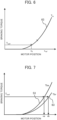
- FIG. 6 is a diagram illustrating the relationship between motor position and braking torque generated by the braking torque-position relationship generation portion during a release according to the second embodiment of the present invention.
- FIG. 7 is a diagram illustrating the relationship between motor position and braking torque generated by the braking torque-position relationship generation portion during a release according to the second embodiment of the present invention.
- FIG. 5 illustrates the relationship between the motor current and motor position acquired during a release operation.
- a stop condition forces the electric motor to operate up to region IV higher than the thrust required for the parking brake.
- the electric motor subsequently operates to once return the thrust necessary for the parking brake, acquiring a relationship 61 between motor current I and motor position x in region IV.
- the parking brake during parking is thereafter released to acquire a relationship 62 between the motor current and motor position during the release in the order of III, II, and I. Similar to the applying operation, it is possible to acquire the relationship between effective current Ir and motor position x in consideration of motor current I0 for friction.
- the electric motor operates to lower the current from II to I in FIG. 5 , acquiring the relationship 61 between motor position x and motor current I.
- the brake pad causes a clearance
- the current in region I becomes almost constant, acquiring motor current I0 comparable to the friction.
- the braking torque estimation portion 41 can be estimated from the vehicle conditions, similar to the applying operation, for example.
- the braking torque is estimated when the brake is released. At this time it is possible to estimate the braking torque Tbx0 at motor position x0 by simultaneously measuring also the motor position.
- effective motor current Ir at motor position x0 can also be acquired from FIG. 5 .
- the proportionality coefficient can be calculated because effective motor current Ir is proportional to the generated braking torque.
- Ktir Tbx 0 / Ix 0
- the forward efficiency and the reverse efficiency do not necessarily match.
- two characteristics are acquired, namely, characteristic (Tba-x) 53 at the applying side and characteristic (Tbr-x) 63 at the release side.
- the braking torque position command conversion portion 36 identifies an applying operation or a release operation, converts input control torque command Tbref into motor position command xref, and outputs the command to the position current control portion 44.
- the position current control portion 44 compares motor position command xref with the value detected by the position detection portion 32 and provides feedback control.
- the motor position command is converted into an electric current command and is output to the electric motor 8.
- the present embodiment processes commands based on the distinction between the applying operation and the release operation, making it possible to highly accurately control the braking torque according to the operations.
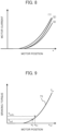
- FIG. 8 is a diagram illustrating the relationship between motor position and motor current used for a braking torque position command conversion portion according to the third embodiment of the present invention.
- FIG. 9 is a diagram illustrating the relationship between motor position and braking torque generated by the braking torque-position relationship generation portion according to the third embodiment of the present invention.
- the third embodiment describes examples in consideration of characteristics changes due to differences in environments such as the environment (environment A) where the motor position-current relationship generation portion 43 acquires the relationship between motor position and motor current as explained in the first and second embodiments; the environment (environment B) where the braking torque estimation portion 41 estimates the braking torque; and the environment (environment C) where control is provided based on the result.
- the torque generated by the electric motor 8 or the thrust converted through the rotation-to-linear movement is converted into braking torque.
- the friction coefficient of brake pads may also vary with the temperature and the rotational speed.
- the motor position-current relationship generation portion 43 previously stores or formulates the relationship with environmental changes.
- a conversion equation such as equation 8 is provided.
- An example formulation represents that motor position x, generating the same thrust, changes as expressed in the following equation.
- x a ⁇ Tpad + b
- Tpad denotes the brake pad temperature
- a and b respectively denote the slope and the intercept referring to the temperature. This value is used to estimate the characteristics under standard conditions (such as room temperature).
- characteristics (1) in FIG. 8 are acquired under environment A where the brake pad temperature is 300 °C and the motor temperature is 60 °C.
- the characteristics are converted once based on equation 8 using room temperature for the brake pads 5a and 5b.
- resulting characteristics (2) are acquired.
- the torque constant usually decreases as the motor temperature decreases.
- the motor current decreases at points where the same torque is generated.
- characteristics (3) are acquired under the condition of room temperature for the motor and the brake pads.
- the brake pad temperature and the motor temperature may be directly measured or may be estimated from the number of operations.
- the braking torque is found by multiplying the thrust resulting from the electric motor 8 by the friction coefficient between the set of brake pads 5a and 5b and the disc rotor 2.
- the friction coefficient varies with environments such as the temperature and relative speed of contacting objects.
- the braking torque estimation portion 41 estimates or measures the temperature and relative speed of the brake pads 5a and 5b.
- the standard condition (such as room temperature and speed V0) is determined to calculate the braking torque and motor position (Tbx0, x0) under the standard condition referring to the measured braking torque and motor position (Tbx0m, x0m) as illustrated in FIG. 9 .
- Characteristics (3) in FIG. 8 are multiplied by proportionality coefficient Ktir, for example, to acquire a relationship 71 between motor position x and braking torque Tba or Tbr indicated by the solid line in FIG. 9 .
- the relationship 71 between braking torque and motor position is calculated under the environment (environment C) (motor temperature, brake pad temperature, and relative speed), to provide control based on the relationship between braking torque and motor position in standard conditions.
- the control torque command may be calculated based on this relationship.
- the motor position is output as a motor position command to the position current control portion.
- the present embodiment can highly accurately control the braking torque despite differences in the environment (environment A) where the motor position-current relationship generation portion 43 acquires the relationship between motor position and motor current; the environment (environment B) where the braking torque estimation portion 41 estimates the braking torque; and the environment (environment C) where control is provided based on the result.
- the description below explains a fourth embodiment.
- the fourth embodiment explains the timing to update the relationship between braking torque and motor position in the braking torque-position relationship generation portion 42 as explained in the first through third embodiments.
- proportionality coefficient Ktia or Ktir between the effective motor current and the generated braking torque practically changes over time at a small rate.
- the proportionality coefficient converted into the standard state is subject to a small change. For example, consider Ktia or Ktir detected during the braking torque estimation changes significantly (such as a change of 10% or more) from the previous value. In such a case, the detected value is evaluated as noise and is not adopted. Instead, the previous value is adopted. Thus, errors can be reduced.
- the braking torque-position relationship generation portion 42 may acquire the braking torque value estimated by the braking torque estimation portion 41 multiple times.
- the acquired braking torque values may be averaged or filtered.
- the filtered value Ktia or Ktir may be used to acquire and update the relationship between the rotational position and the braking torque of the electric motor 8. This makes it possible to reduce error factors and improve accuracy.
- the electric motor may operate a piston in various brakes such as a drum brake. It may be favorable to generate a braking force by pressing the brake lining against the brake drum as a rotating body.
Landscapes
- Engineering & Computer Science (AREA)
- Mechanical Engineering (AREA)
- Transportation (AREA)
- General Engineering & Computer Science (AREA)
- Power Engineering (AREA)
- Regulating Braking Force (AREA)
- Braking Systems And Boosters (AREA)
- Braking Arrangements (AREA)
Abstract
It is an object of the present invention to provide an electric brake device capable of accurate control at low cost. The present invention includes a motor control device 11 that controls rotation of an electric motor 8 for pressing brake pads 5a, 5b. The motor control device 11 is provided with: a motor position-current relationship generation portion 43 that acquires a relationship between the rotational position and the current of the electric motor 8; a braking torque estimation portion 41 that estimates braking torque pressing the brake pads 5a, 5b, on the rotational position of the electric motor 8; and a braking torque-position relationship portion generation portion 42 that acquires a relationship between the rotational position and the braking torque of the electric motor 8 on the basis of information from the motor position-current relationship generation portion 43 and the braking torque estimation portion 41. The rotation of the electric motor 8 is controlled on the basis of information from the braking torque-position relationship portion generation portion 42.
Description
- The present invention relates to an electric brake device used to brake vehicles.
- An electric brake device enables more precise control over braking force by accurately estimating the braking force. A thrust sensor can be used to estimate the braking force and thereby improve the estimation accuracy, but the cost increases. For example,
patent literature 1 proposes the technology as a method to estimate braking force without using a thrust sensor. - According to
patent literature 1, a driving force is applied to drive wheels while a braking force is applied to the wheels. The technology calibrates control parameters to drive the electric motor of a brake mechanism provided for the wheels based on a driving wheel driving force that exceeds the braking force. - Patent Literature 1: International Publication
WO2020/262278 - The technology described in
patent literature 1 needs to compare a braking force with a driving force when estimating the braking force and needs to generate the driving force and correct the control parameters. As one issue, highly accurate sensors are required to acquire accurate driving force information, increasing costs. As another issue, the drive wheels need to move especially to acquire accurate driving force information without the use of high-precision sensors, complicating the control. - It is an object of the present invention to provide an electric brake device capable of accurate control at low cost. Solution to Problem
- To achieve the above-described object, an electric brake device according to the present invention includes an electric motor, a straight-moving portion, a brake pad, and a motor control device. The straight-moving portion moves through rotations of the electric motor. The brake pad presses a disc rotor that rotates along with a wheel through a thrust generated by movement of the straight-moving portion. The motor control device controls the rotations of the electric motor. The motor control device includes a motor position-current relationship generation portion, a braking torque estimation portion, and a braking torque-position relationship generation portion. The motor position-current relationship generation portion acquires a relationship between rotational position and the current of the electric motor. The braking torque estimation portion estimates a braking torque pressing the brake pad based on the rotational positions of the electric motor at a predetermined timing. The braking torque-position relationship generation portion that acquires a relationship between rotational position and the braking torque of the electric motor based on information from the motor position-current relationship generation portion and the braking torque estimation portion. The motor control device controls rotations of the electric motor based on information from the braking torque-position relationship generation portion.
- The present invention can provide an electric brake device capable of accurate control at low cost.
-
-
FIG. 1 is a schematic diagram of an electric brake device according to a first embodiment of the present invention; -
FIG. 2 is a control block diagram of the electric brake device according to the first embodiment of the present invention; -
FIG. 3 is a diagram illustrating a relationship between motor current and motor position acquired by a motor position-current relationship generation portion according to the first embodiment of the present invention; -
FIG. 4 is a diagram illustrating a relationship between motor position and braking torque generated by a braking torque position-current relationship generation portion according to the first embodiment of the present invention; -
FIG. 5 is a diagram illustrating the relationship between motor current and motor position acquired by the motor position-current relationship generation portion during a release operation according to a second embodiment of the present invention; -
FIG. 6 is a diagram illustrating the relationship between motor position and braking torque generated by the braking torque-position relationship generation portion during a release according to the second embodiment of the present invention; -
FIG. 7 is a diagram illustrating the relationship between motor position and braking torque generated by the braking torque-position relationship generation portion during a release according to the second embodiment of the present invention; -
FIG. 8 is a diagram illustrating the relationship between motor position and motor current used for a braking torque position command conversion portion according to a third embodiment of the present invention; and -
FIG. 9 is a diagram illustrating the relationship between motor position and braking torque generated by the braking torque-position relationship generation portion according to the third embodiment of the present invention. - The description below explains embodiments of the present invention by reference to the accompanying drawings. The same reference numerals or symbols may be used for substantially the same or similar configurations. A duplicate description may be omitted.
- The description below explains the electric brake device described in the first embodiment.
FIG. 1 is a schematic diagram of the electric brake device according to the first embodiment of the present invention.FIG. 2 is a control block diagram of the electric brake device according to the first embodiment of the present invention. - Generally, a vehicle such as a car includes four wheels such as right and left front wheels and right and left rear wheels. A brake device is provided for each wheel. As illustrated in
FIG. 1 , thebrake device 1 includes ahousing 4,brake pads electric motor 8, for example. Thehousing 4 is supported to be floatable on a carrier (unshown) in the axial direction of a disc rotor 2 (rotating member). The carrier is secured to a non-rotating portion of the vehicle, the portion being positioned toward the inside of the vehicle away from thedisc rotor 2. Thebrake pads disc rotor 2. Thepiston 6 can straight move inside thehousing 4. Theelectric motor 8 drives thepiston 6. Theelectric motor 8 supplies thrust to thebrake pads linear conversion mechanism 10 and thepiston 6. Thebrake pads disc rotor 2, rotating along with the wheels, and provide braking force based on a clamping force (pad thrust). - An output shaft of the
electric motor 8 is connected to areducer 9. An output shaft of thereducer 9 is connected to the rotation-to-linear conversion mechanism 10. The rotation-to-linear conversion mechanism 10 enables thepiston 6 to move straight. Thepiston 6 straight moves based on the rotation of theelectric motor 8. - According to the first embodiment, the
disc rotor 2, thehousing 4, thebrake pads piston 6, theelectric motor 8, thereducer 9, and the rotation-to-linear conversion mechanism 10 configure abrake caliper 3. The rotation-to-linear conversion mechanism 10 and thepiston 6 configure a straight-moving portion. - The
electric motor 8 connects to a motor control device 11 (controller) via anelectric wire 12. Themotor control device 11 controls rotations of theelectric motor 8. As illustrated inFIG. 1 , theelectric motor 8 and themotor control device 11 are separated from each other but may be integrated. As illustrated inFIG. 2 , theelectric motor 8 includes acurrent detection portion 31 and aposition detection portion 32 to detect applied currents. - The
motor control device 11 receives acontrol torque command 29 from a high-order control device (vehicle control ECU), for example. Themotor control device 11 supplies an electric current command to theelectric motor 8 based on a predetermined control program, for example, by using values detected in thecurrent detection portion 31 and theposition detection portion 32. - A
control signal line 21 andcommunication lines motor control device 11. Thecontrol signal line 21 supplies themotor control device 11 with a control command from a high-order control device such as a vehicle control ECU (Electronic Control Unit). The communication lines 22 and 23 are used to communicate with the high-order control device by supplying information other than control commands. According to the example, the high-order control device and themotor control device 11 are provided separately but may be integrated into a control device. -
FIG. 2 illustrates a calculation method of themotor control device 11. Thecontrol torque command 29 is supplied from the vehicle control ECU via thecontrol signal line 21. Thecontrol torque command 29 is converted into a position command value in a braking torque positioncommand conversion portion 36 and is input to a positioncurrent control portion 44. The positioncurrent control portion 44 feeds back position information acquired from theposition detection portion 32 based on a position command and current values of theelectric motor 8 acquired by thecurrent detection portion 31. An electric current command is then supplied to theelectric motor 8 in thebrake caliper 3. - The braking torque position
command conversion portion 36 converts the input control torque command into a motor position command and outputs based on the relationship between motor position and braking torque, the relationship being generated based on a braking torque-position relationshipportion generation portion 42. The relationship is expressed as a braking torque position map that represents braking torque positions in a map form, for example. The braking torque-position relationshipportion generation portion 42 is generated from the relationship between motor position and motor current generated by the motor position-currentrelationship generation portion 43 and outputs from the brakingtorque estimation portion 41. - The description below explains the motor position-current
relationship generation portion 43.FIG. 3 is a diagram illustrating a relationship between motor current and motor position acquired by a motor position-current relationship generation portion according to the first embodiment of the present invention. The motor position-currentrelationship generation portion 43 acquires the rotational position and the current of theelectric motor 8 and generates a relationship between the rotational position and the current of theelectric motor 8. - The
electric motor 8 includes thecurrent detection portion 31 and theposition detection portion 32. When a brake is operated during travel, for example, thebrake pads relationship 51 between motor position x and motor current I as illustrated inFIG. 3 . At this time, motor current I usually contains a noise component. It is preferable to perform filtering by using a lowpass filter, for example. Motor current I contains a friction component (motor current I0 corresponding to the friction component) generated from a rotation-to-linear moving portion, for example. The friction component can be estimated from the current in a clearance area before the pad contact, for example. Motor position-current relationship 52 can be acquired by extracting effective motor current Ia to the exclusion of the friction component. When the motor operation causes a large acceleration/deceleration, it is possible to extract an effective motor current component more highly accurately by excluding an inertia component as needed. - The description below explains the conditions to acquire the above-described relationship. During normal travel, the brake force is used only within a small range to operate the brake only in a range of states I and II illustrated in
FIG. 3 , for example. InFIG. 3 , state I shows a pad clearance that causes no braking force yet. Motor current I0 for the friction component is acquired in state I. - Then, state II is used to acquire characteristics in a region that generates a low thrust. State II allows the
brake pads disc rotor 2 during normal travel to acquire a braking force. Normal travel provides characteristics of a high thrust range that occurs less frequently. When the travel stops, operation III is performed to further increase the thrust. It is possible to acquire the relationship between motor position and motor current until the parking brake generates the thrust. Furthermore, the thrust may be temporarily increased to be larger than the thrust required for parking. The relationship between motor position and motor current can thereby be acquired in region IV corresponding to a higher thrust. - As above, the motor position-current
relationship generation portion 43 acquires the relationship between the rotational position and the current of theelectric motor 8 separately based on whether the vehicle travels or stops. The present embodiment can provide the relationship between motor position x and motor current I as non-linear characteristics in the entire range of braking force that needs to be generated up to a high thrust. - Next, the description below explains the braking
torque estimation portion 41 that estimates a braking torque to press thebrake pads - Suppose longitudinal tire force Ftx causes a stop force by braking. Longitudinal tire force Ftx is expressed as a function of tire load Ftz. Longitudinal tire force Ftx can be approximated linearly in the range of small braking force and is proportional to slip ratio λ as expressed by
equation 1 below.

- In the equations, Vb denotes the vehicle speed, Vw denotes the value acquired by converting the wheel speed into the position of the center of gravity, and Kw denotes the proportionality coefficient determined by tire characteristics, for example.
- Therefore, longitudinal force Ftx can be estimated by finding vehicle speed Vb, wheel speed Vw, tire load Ftz, and proportionality coefficient Kw. Longitudinal tire force Ftx includes braking/driving force Fd generated by the engine of an engine vehicle or the main motor of an electric vehicle. As seen from
equation 3, braking/driving force Fd is subtracted from tire load Ftz to yield a value corresponding to the braking force due to the braking torque. Braking force Fb can be estimated by subtracting (excluding) the braking/driving force generated by the engine or motor from the estimated value.
- Tire load Ftz is estimated through the use of the vehicle weight by taking into account variations due to the roll and pitch motions of the vehicle body.
- Braking torque Tb can be estimated by multiplying braking force Fb by tire radius R. At this time, rotational position x (motor position) of the
electric motor 8 is also measured, making it possible to determine the relationship between that value and the estimated braking torque. The example represents the motor rotation position as position x. However, it may be also favorable to measure or estimate a straight movement displacement that corresponds to the straight-moving portion such as thepiston 6, and is converted by the rotation-to-linear moving portion. This makes it possible to estimate braking torque Tbx0 at motor position x0 inFIG. 4 , for example.FIG. 4 is a diagram illustrating a relationship between motor position and braking torque generated by a braking torque position-current relationship generation portion according to the first embodiment of the present invention. - To estimate the braking torque, the braking
torque estimation portion 41 requires estimating tire load Ftz, wheel speed Vw, and braking/driving force Fd as described above. The description below explains the corresponding estimation timings. - For example, suppose a clutch is used to break the connection between the wheel and the engine or the main motor that drives the wheel, resulting in braking/driving force Fd = 0. Estimation of braking/driving force Fd is unnecessary, eliminating possible errors due to the estimation. Suppose the influence of braking/driving force Fd is small. The relationship between tire load Ftz and braking/driving force Fd is Ftz » Fd. It is possible to decrease the influence of errors resulting from the estimation of braking/driving force Fd.
- While the vehicle is turning, the estimation needs to take into account that tire load Ftz varies with the right and left sides and also needs to be estimated and the wheel speed of each wheel needs to be converted into the center of gravity position. Estimation errors can be reduced by limiting the estimation to straight travel.
- A slope, if any, may affect the acceleration and deceleration to increase estimation errors. Estimation errors can be reduced by limiting the estimation to small slopes.
- As above, factors in estimation errors can be removed by selecting some conditions to reduce error factors at given timings. The estimation accuracy can be improved.
- In addition to the methods described above, the braking torque may be estimated based on information from various sensors that acquire vehicle information. Examples of various sensors include acceleration sensors, yaw rate sensors, steering angle sensors, and GPS (Global Positioning System). At least one of these is used. The above-described information is comparable to
sensor information 40 inFIG. 2 and is input to the brakingtorque estimation portion 41. - The description below explains the braking torque-position
relationship generation portion 42. The braking torque-positionrelationship generation portion 42 acquires the relationship between rotational position and braking torque of theelectric motor 8 based on the information from the motor position-currentrelationship generation portion 43 and the brakingtorque estimation portion 41. - The motor position-current
relationship generation portion 43 determines the relationship between motor current I and motor position x. Therefore, motor current Iax0 at motor position x0 is to be estimated in the brakingtorque estimation portion 41 and can also be calculated from the relationship acquired by the motor position-currentrelationship generation portion 43. - Normally, the effective motor current component and the motor generate a torque that is proportional to the resulting braking torque. Therefore, the following equation can be used to calculate proportionality coefficient Ktia.

- It may be favorable to increase the accuracy of proportional coefficient Ktia by using data at multiple points, for example. An average of data at multiple points can be used for calculation to provide high accuracy. The accuracy can be further improved by removing a noise value, if any, that deviates significantly from other values at multiple points. The following equation expresses braking torque Tba using Ktia.

- The entire characteristics of motor current Ia and motor position, illustrated in
FIG. 3 , are multiplied by Ktia to acquire a relationship 53 (FIG. 4 ) between braking torque Tba and motor position x. - The description below explains the braking torque control method, again. When the
control torque command 29, Tbref, is input from a higher level, the braking torque positioncommand conversion portion 36 finds motor position xref based on therelationship 53 between braking torque Tb and motor position x, as illustrated inFIG. 4 . Position command xref is input to the positioncurrent control portion 44 and is compared with the value detected by theposition detection portion 32 to provide feedback control. The position command is then converted into an electric current command that is output to theelectric motor 8. Thecontrol torque command 29 may be replaced by a command value simply representing the braking force applied to the tires. - The present embodiment can provide highly accurate braking torque control in consideration of differences in rigidity of parts usually characterized by large individual differences, differences in characteristics between positions and braking torque depending on differences in motor characteristics, and characteristics between motor position and braking torque that are detected during normal braking operations and are subject to aging variations. The present embodiment can reduce costs without using a thrust sensor for braking torque control.
- The description below explains the second embodiment of the present invention. The second embodiment explains how to generate a map during release operation while the first embodiment describes the map generation during the applying operation.
FIG. 5 is a diagram illustrating the relationship between motor current and motor position acquired by the motor position-current relationship generation portion during a release operation according to the second embodiment of the present invention.FIG. 6 is a diagram illustrating the relationship between motor position and braking torque generated by the braking torque-position relationship generation portion during a release according to the second embodiment of the present invention.FIG. 7 is a diagram illustrating the relationship between motor position and braking torque generated by the braking torque-position relationship generation portion during a release according to the second embodiment of the present invention. -
FIG. 5 illustrates the relationship between the motor current and motor position acquired during a release operation. As explained in the first embodiment, a stop condition forces the electric motor to operate up to region IV higher than the thrust required for the parking brake. The electric motor subsequently operates to once return the thrust necessary for the parking brake, acquiring arelationship 61 between motor current I and motor position x in region IV. The parking brake during parking is thereafter released to acquire arelationship 62 between the motor current and motor position during the release in the order of III, II, and I. Similar to the applying operation, it is possible to acquire the relationship between effective current Ir and motor position x in consideration of motor current I0 for friction. - Suppose the applying operation is performed and then the release operation is performed also during traveling. In this case, the electric motor operates to lower the current from II to I in
FIG. 5 , acquiring therelationship 61 between motor position x and motor current I. When the brake pad causes a clearance, the current in region I becomes almost constant, acquiring motor current I0 comparable to the friction. - Next, the description below explains the braking
torque estimation portion 41. The braking torque can be estimated from the vehicle conditions, similar to the applying operation, for example. The braking torque is estimated when the brake is released. At this time it is possible to estimate the braking torque Tbx0 at motor position x0 by simultaneously measuring also the motor position. - Similar to the applying operation, effective motor current Ir at motor position x0 can also be acquired from
FIG. 5 . - The proportionality coefficient can be calculated because effective motor current Ir is proportional to the generated braking torque.

- Similar to the applying operation, it may be favorable to find this proportionality coefficient Ktir from multiple points. The braking torque can be expressed as the following equation using Ktir.

- Thus, the entire characteristics of motor current Ir and motor position x, illustrated in
FIG. 5 , are multiplied by Ktit to acquire a relationship 63 (FIG. 6 ) between braking torque Tb and motor position x. - Generally, the forward efficiency and the reverse efficiency do not necessarily match. As illustrated in
FIG. 7 , two characteristics are acquired, namely, characteristic (Tba-x) 53 at the applying side and characteristic (Tbr-x) 63 at the release side. - Based on the characteristics, the braking torque position
command conversion portion 36 identifies an applying operation or a release operation, converts input control torque command Tbref into motor position command xref, and outputs the command to the positioncurrent control portion 44. The positioncurrent control portion 44 compares motor position command xref with the value detected by theposition detection portion 32 and provides feedback control. The motor position command is converted into an electric current command and is output to theelectric motor 8. - The present embodiment processes commands based on the distinction between the applying operation and the release operation, making it possible to highly accurately control the braking torque according to the operations.
- Next, the description below explains the third embodiment of the present invention by using
FIGS. 8 and 9. FIG. 8 is a diagram illustrating the relationship between motor position and motor current used for a braking torque position command conversion portion according to the third embodiment of the present invention.FIG. 9 is a diagram illustrating the relationship between motor position and braking torque generated by the braking torque-position relationship generation portion according to the third embodiment of the present invention. - The third embodiment describes examples in consideration of characteristics changes due to differences in environments such as the environment (environment A) where the motor position-current
relationship generation portion 43 acquires the relationship between motor position and motor current as explained in the first and second embodiments; the environment (environment B) where the brakingtorque estimation portion 41 estimates the braking torque; and the environment (environment C) where control is provided based on the result. - For example, rigidity changes due to contraction and expansion of brake pads and devices due to temperature. The relationship between motor current I and motor position x varies with changes in the torque constant of the
electric motor 8. - The torque generated by the
electric motor 8 or the thrust converted through the rotation-to-linear movement is converted into braking torque. In this case, the friction coefficient of brake pads may also vary with the temperature and the rotational speed. - According to the third embodiment, the motor position-current
relationship generation portion 43 previously stores or formulates the relationship with environmental changes. For example, a conversion equation such asequation 8 is provided. An example formulation represents that motor position x, generating the same thrust, changes as expressed in the following equation.
- For example, suppose characteristics (1) in
FIG. 8 are acquired under environment A where the brake pad temperature is 300 °C and the motor temperature is 60 °C. In this case, the characteristics are converted once based onequation 8 using room temperature for thebrake pads - The brake pad temperature and the motor temperature may be directly measured or may be estimated from the number of operations.
- Meanwhile, the braking torque is found by multiplying the thrust resulting from the
electric motor 8 by the friction coefficient between the set ofbrake pads disc rotor 2. However, the friction coefficient varies with environments such as the temperature and relative speed of contacting objects. When the acquired environment changes to a different one, the brakingtorque estimation portion 41 estimates or measures the temperature and relative speed of thebrake pads FIG. 9 . - The values in the standard state are classified into the applying operation and the release operation as needed to calculate the proportionality coefficient based on
equation - Characteristics (3) in
FIG. 8 are multiplied by proportionality coefficient Ktir, for example, to acquire arelationship 71 between motor position x and braking torque Tba or Tbr indicated by the solid line inFIG. 9 . - When further control is required, the
relationship 71 between braking torque and motor position is calculated under the environment (environment C) (motor temperature, brake pad temperature, and relative speed), to provide control based on the relationship between braking torque and motor position in standard conditions. The control torque command may be calculated based on this relationship. In such a case, the motor position is output as a motor position command to the position current control portion. - The present embodiment can highly accurately control the braking torque despite differences in the environment (environment A) where the motor position-current
relationship generation portion 43 acquires the relationship between motor position and motor current; the environment (environment B) where the brakingtorque estimation portion 41 estimates the braking torque; and the environment (environment C) where control is provided based on the result. - The description below explains a fourth embodiment. The fourth embodiment explains the timing to update the relationship between braking torque and motor position in the braking torque-position
relationship generation portion 42 as explained in the first through third embodiments. - As calculated in the first through third embodiments, proportionality coefficient Ktia or Ktir between the effective motor current and the generated braking torque practically changes over time at a small rate. In particular, as explained in the third embodiment, the proportionality coefficient converted into the standard state is subject to a small change. For example, consider Ktia or Ktir detected during the braking torque estimation changes significantly (such as a change of 10% or more) from the previous value. In such a case, the detected value is evaluated as noise and is not adopted. Instead, the previous value is adopted. Thus, errors can be reduced.
- The braking torque-position
relationship generation portion 42 may acquire the braking torque value estimated by the brakingtorque estimation portion 41 multiple times. The acquired braking torque values may be averaged or filtered. The filtered value Ktia or Ktir may be used to acquire and update the relationship between the rotational position and the braking torque of theelectric motor 8. This makes it possible to reduce error factors and improve accuracy. - The above-described embodiments have illustrated the electric brake using the disc brake. However, for example, the electric motor may operate a piston in various brakes such as a drum brake. It may be favorable to generate a braking force by pressing the brake lining against the brake drum as a rotating body.
- 1: brake device, 2: disc rotor, 3: brake caliper, 4: housing, 5a, 5b: brake pad, 6: piston, 8: electric motor, 9: reducer, 10: rotation-to-linear conversion mechanism, 11: motor control device, 29: control torque command, 31: current detection portion, 32: position detection portion, 36: braking torque position command conversion portion, 41: braking torque estimation portion, 42: braking torque-position relationship generation portion, 43: motor position-current relationship generation portion, 44: position current control portion
Claims (14)
- An electric brake device comprising: an electric motor; a straight-moving portion that moves through rotations of the electric motor; a brake pad pressing a disc rotor that rotates along with a wheel through a thrust generated by movement of the straight-moving portion; and a motor control device that controls rotations of the electric motor,
wherein the motor control device includes:a motor position-current relationship generation portion that acquires a relationship between rotational position and current of the electric motor;a braking torque estimation portion that estimates a braking torque pressing the brake pad based on rotational positions of the electric motor at a predetermined timing; anda braking torque-position relationship generation portion that acquires a relationship between rotational position and the braking torque of the electric motor based on information from the motor position-current relationship generation portion and the braking torque estimation portion; andwherein the motor control device controls rotations of the electric motor based on information from the braking torque-position relationship generation portion. - The electric brake device according to claim 1,
wherein the braking torque estimation portion estimates a braking torque when a vehicle travels straight. - The electric brake device according to claim 2,
wherein, when the braking torque estimation portion estimates a braking torque, the electric brake device causes a disconnect between the wheel and an engine or a main motor to drive the wheel. - The electric brake device according to claim 1,
wherein the motor position-current relationship generation portion acquires a relationship between rotational position and current of the electric motor separately based on whether a vehicle travels or stops. - The electric brake device according to claim 1,
wherein the motor position-current relationship generation portion acquires a relationship between rotational position and current of the electric motor separately depending on whether an applying operation or a release operation is active. - The electric brake device according to claim 1,
wherein the motor position-current relationship generation portion acquires a relationship between rotational position and current of the electric motor during an applying operation or a release operation. - The electric brake device according to claim 3,
wherein the braking torque estimation portion estimates a braking torque by excluding a braking/driving force generated by the engine or the main motor. - The electric brake device according to claim 1,
wherein the braking torque estimation portion estimates a braking torque based on information from a sensor that acquires vehicle information. - The electric brake device according to claim 8,
wherein the sensor represents at least one of acceleration sensor, yaw rate sensor, steering angle sensor, or GPS (Global Positioning System). - The electric brake device according to claim 1,
wherein the braking torque estimation portion estimates a braking torque based on a tire load and a slip ratio. - The electric brake device according to claim 1,
wherein the braking torque-position relationship generation portion acquires a braking torque value estimated by the braking torque estimation portion multiple times, filters acquired braking torque values, and acquires a relationship between a rotational position and the braking torque of the electric motor. - The electric brake device according to claim 1,
wherein the motor position-current relationship generation portion acquires a relationship between position and motor current by estimating characteristics applied to change to a different environment from an environment used to acquire a relationship between rotational position and current of the electric motor. - The electric brake device according to claim 1,
wherein the braking torque estimation portion estimates a braking torque applied to change to a different environment from an environment used to acquire a braking torque. - The electric brake device according to claim 1, comprising:
a braking torque position command conversion portion that outputs a position command for the electric motor based on information from the braking torque-position relationship generation portion.
Applications Claiming Priority (2)
| Application Number | Priority Date | Filing Date | Title |
|---|---|---|---|
| JP2022096726A JP7795976B2 (en) | 2022-06-15 | 2022-06-15 | Electric brake device |
| PCT/JP2023/017701 WO2023243266A1 (en) | 2022-06-15 | 2023-05-11 | Electric brake device |
Publications (2)
| Publication Number | Publication Date |
|---|---|
| EP4541673A1 true EP4541673A1 (en) | 2025-04-23 |
| EP4541673A4 EP4541673A4 (en) | 2026-07-15 |
Family
ID=89191014
Family Applications (1)
| Application Number | Title | Priority Date | Filing Date |
|---|---|---|---|
| EP23823569.1A Pending EP4541673A4 (en) | 2022-06-15 | 2023-05-11 | ELECTRIC BRAKE DEVICE |
Country Status (6)
| Country | Link |
|---|---|
| US (1) | US20250368170A1 (en) |
| EP (1) | EP4541673A4 (en) |
| JP (1) | JP7795976B2 (en) |
| KR (1) | KR20240174105A (en) |
| CN (1) | CN119451871A (en) |
| WO (1) | WO2023243266A1 (en) |
Families Citing this family (1)
| Publication number | Priority date | Publication date | Assignee | Title |
|---|---|---|---|---|
| JPWO2025253672A1 (en) * | 2024-06-07 | 2025-12-11 |
Family Cites Families (6)
| Publication number | Priority date | Publication date | Assignee | Title |
|---|---|---|---|---|
| JP2008049800A (en) * | 2006-08-24 | 2008-03-06 | Hitachi Ltd | Electric brake device and control method thereof |
| JP4902373B2 (en) * | 2007-01-30 | 2012-03-21 | 本田技研工業株式会社 | Brake device and control method of brake device |
| JP5582293B2 (en) * | 2010-03-31 | 2014-09-03 | 日立オートモティブシステムズ株式会社 | Electric brake device |
| JP2018121461A (en) * | 2017-01-26 | 2018-08-02 | Ntn株式会社 | Motor-driven direct-acting actuator and electric brake device |
| JP7089871B2 (en) * | 2017-12-29 | 2022-06-23 | Ntn株式会社 | Electric brake device |
| CN114026004A (en) | 2019-06-26 | 2022-02-08 | 日立安斯泰莫株式会社 | Electric brake device, brake control device, and control parameter calibration method |
-
2022
- 2022-06-15 JP JP2022096726A patent/JP7795976B2/en active Active
-
2023
- 2023-05-11 EP EP23823569.1A patent/EP4541673A4/en active Pending
- 2023-05-11 CN CN202380044969.6A patent/CN119451871A/en active Pending
- 2023-05-11 KR KR1020247036754A patent/KR20240174105A/en active Pending
- 2023-05-11 US US18/874,449 patent/US20250368170A1/en active Pending
- 2023-05-11 WO PCT/JP2023/017701 patent/WO2023243266A1/en not_active Ceased
Also Published As
| Publication number | Publication date |
|---|---|
| US20250368170A1 (en) | 2025-12-04 |
| EP4541673A4 (en) | 2026-07-15 |
| JP7795976B2 (en) | 2026-01-08 |
| WO2023243266A1 (en) | 2023-12-21 |
| JP2023183216A (en) | 2023-12-27 |
| KR20240174105A (en) | 2024-12-16 |
| CN119451871A (en) | 2025-02-14 |
Similar Documents
| Publication | Publication Date | Title |
|---|---|---|
| EP3472008B1 (en) | A wheel controller for a vehicle | |
| US8954249B2 (en) | Braking force control apparatus for vehicle | |
| US6217131B1 (en) | Method and device for controlling a vehicle braking system in open loop | |
| US20050035653A1 (en) | Electrically actuatable vehicle brake and method for controlling an electrically actuatable vehicle brake | |
| JP6683581B2 (en) | Brake control device | |
| KR20130061728A (en) | Electronic parking brake system, assistant starting method thereof for motor vehicle | |
| JP2019509925A (en) | Device and method for improving the performance of anti-lock braking and anti-slip regulation of vehicles | |
| KR101405189B1 (en) | Braking system for hybrid vehicle and control method for the same | |
| KR20030023007A (en) | The method for estimating the friction coefficient between tires and road surfaces for calculating flexible safe following distance of the vehicle | |
| US10759402B2 (en) | Electric braking system | |
| CN113002515B (en) | Method and system for brake boosting of a vehicle | |
| US12559070B2 (en) | Method for controlling a braking system of a vehicle and system thereof | |
| US7445091B2 (en) | Electrically operated brake | |
| US20250368170A1 (en) | Electric brake device | |
| US20230026361A1 (en) | Method for estimating a brake factor parameter in a braking system, and vehicle implementing the same | |
| US9934626B2 (en) | Brake system | |
| US20240367634A1 (en) | Method for determining operating variables of a drum brake, associated drum brake assembly, analysis device and storage medium | |
| KR102418890B1 (en) | Control device and method for operating an electromechanical brake booster of a brake system of a vehicle | |
| KR102889484B1 (en) | Electric brake system | |
| US6254203B1 (en) | Method for determining the deceleration of a motor vehicle | |
| US20240092330A1 (en) | Method for controlling the tightening torque of an improved electromechanical brake | |
| JP5754265B2 (en) | Tire contact length estimation device | |
| KR100202964B1 (en) | Vehicle braking force calculation setting method | |
| WO2025253672A1 (en) | Electric brake | |
| CN121419906A (en) | Electric braking device |
Legal Events
| Date | Code | Title | Description |
|---|---|---|---|
| STAA | Information on the status of an ep patent application or granted ep patent |
Free format text: STATUS: THE INTERNATIONAL PUBLICATION HAS BEEN MADE |
|
| PUAI | Public reference made under article 153(3) epc to a published international application that has entered the european phase |
Free format text: ORIGINAL CODE: 0009012 |
|
| STAA | Information on the status of an ep patent application or granted ep patent |
Free format text: STATUS: REQUEST FOR EXAMINATION WAS MADE |
|
| 17P | Request for examination filed |
Effective date: 20250115 |
|
| AK | Designated contracting states |
Kind code of ref document: A1 Designated state(s): AL AT BE BG CH CY CZ DE DK EE ES FI FR GB GR HR HU IE IS IT LI LT LU LV MC ME MK MT NL NO PL PT RO RS SE SI SK SM TR |
|
| RAP3 | Party data changed (applicant data changed or rights of an application transferred) |
Owner name: ASTEMO, LTD. |
|
| DAV | Request for validation of the european patent (deleted) | ||
| DAX | Request for extension of the european patent (deleted) | ||
| A4 | Supplementary search report drawn up and despatched |
Effective date: 20260611 |