EP4541655A1 - Headrest with independently adjustable arms and flexible cushion - Google Patents
Headrest with independently adjustable arms and flexible cushion Download PDFInfo
- Publication number
- EP4541655A1 EP4541655A1 EP24207596.8A EP24207596A EP4541655A1 EP 4541655 A1 EP4541655 A1 EP 4541655A1 EP 24207596 A EP24207596 A EP 24207596A EP 4541655 A1 EP4541655 A1 EP 4541655A1
- Authority
- EP
- European Patent Office
- Prior art keywords
- lateral arms
- headrest assembly
- adjustable base
- lateral
- subassembly
- Prior art date
- Legal status (The legal status is an assumption and is not a legal conclusion. Google has not performed a legal analysis and makes no representation as to the accuracy of the status listed.)
- Pending
Links
Images



Classifications
-
- B—PERFORMING OPERATIONS; TRANSPORTING
- B60—VEHICLES IN GENERAL
- B60N—SEATS SPECIALLY ADAPTED FOR VEHICLES; VEHICLE PASSENGER ACCOMMODATION NOT OTHERWISE PROVIDED FOR
- B60N2/00—Seats specially adapted for vehicles; Arrangement or mounting of seats in vehicles
- B60N2/80—Head-rests
- B60N2/885—Head-rests provided with side-rests
-
- B—PERFORMING OPERATIONS; TRANSPORTING
- B64—AIRCRAFT; AVIATION; COSMONAUTICS
- B64D—EQUIPMENT FOR FITTING IN OR TO AIRCRAFT; FLIGHT SUITS; PARACHUTES; ARRANGEMENT OR MOUNTING OF POWER PLANTS OR PROPULSION TRANSMISSIONS IN AIRCRAFT
- B64D11/00—Passenger or crew accommodation; Flight-deck installations not otherwise provided for
- B64D11/06—Arrangements of seats, or adaptations or details specially adapted for aircraft seats
- B64D11/0639—Arrangements of seats, or adaptations or details specially adapted for aircraft seats with features for adjustment or converting of seats
- B64D11/0642—Adjustable headrests
-
- B—PERFORMING OPERATIONS; TRANSPORTING
- B60—VEHICLES IN GENERAL
- B60N—SEATS SPECIALLY ADAPTED FOR VEHICLES; VEHICLE PASSENGER ACCOMMODATION NOT OTHERWISE PROVIDED FOR
- B60N2/00—Seats specially adapted for vehicles; Arrangement or mounting of seats in vehicles
- B60N2/70—Upholstery springs ; Upholstery
- B60N2/7005—Upholstery springs ; Upholstery detachable
Definitions
- the present disclosure relates generally to an adjustable headrest, and more particularly, to a headrest assembly including an adjustment subassembly providing a highly configurable support provision for the sides of the head.
- Safety typically pertains to the seat frame construction and material performance
- comfort typically pertains to the seat adjustability, ergonomics, cushioning, and climatization.
- Headrests are one example of a seat element that provides both comfort and support.
- a seat may include a separate headrest that serves to center the head with respect to the backrest, provide additional cushioning, and in some cases include a provision for sleeping.
- some headrests may be adjustable depending on the user and user preference, adjustability is typically limited to height and/or tilt.
- conventional headrests are not able to achieve a 'cupping' shape considering fixed attachments of the cushion to the underlying support structure.
- a headrest with a provision of support that is more configurable to the side of the head, as well as providing an enveloping experience for the user.
- embodiments of the inventive concepts disclosed herein are directed to a headrest assembly including a fixed base mountable to a seat, an adjustment subassembly, and a cushion subassembly slidably coupled to the adjustment assembly.
- the adjustment subassembly includes an adjustable base movably mounted to the fixed base configured for up and down adjustment, and a plurality of lateral arms extending from the adjustable base, each arm including a segment rotatably connected to the adjustable base, and each lateral arm configured for independent forward and back adjustment.
- the cushion assembly includes a flexible cushion, and a plurality of supports slidably coupling the flexible cushion to the adjustment subassembly, each support having one end slidably engaging one of the segments.
- the cushion subassembly further includes additional supports each having one end slidably engaging the adjustable base.
- the adjustment subassembly includes four lateral arms.
- two of the four lateral arms extend laterally from a left side of the adjustable base, two of the four lateral arms extend laterally from a right side of the adjustable base, and the four lateral arms are symmetrical about a vertical line drawn through the adjustable base.
- two of the four lateral arms extend laterally from a left side of the adjustable base, two of the four lateral arms extend laterally from a right side of the adjustable base, and the four lateral arms are asymmetrical about a horizontal line drawn through the adjustable base.
- the four lateral arms are grouped into an upper pair of lateral arms and a lower pair of lateral arms, the upper pair of lateral arms are aligned along a substantially horizontal axis, and the lower pair of lateral arms are angled relative to the substantially horizontal axis.
- two of the four lateral arms one positioned on each side of the adjustable base, each include an additional segment rotatably attached to their respective segment, and the support associated with each of the two of the four lateral arms slidably engages the additional segment.
- the lateral arms including the additional segment are longer than the lateral arms without the additional segment.
- the four lateral arms are arranged to form an X-shape.
- each of the lateral arms is independently adjustable between a stowed position substantially aligned with a curvature of the adjustable base, and a deployed position forward of and angled relative to the curvature of the adjustable base.
- the cushion subassembly includes relief cuts in the flexible cushion positioned proximal to the rotatable connections of the segments.
- the adjustment subassembly has a larger radius and lower curvature when the plurality of lateral arms are stowed as compared to when the plurality of lateral arms are deployed forward.
- embodiments of the inventive concepts disclosed herein are directed to an aircraft passenger seat including a backrest and a headrest assembly as provided above.
- inventive concepts are not limited in their application to the details of construction and the arrangement of the components or steps or methodologies set forth in the following description or illustrated in the drawings.
- inventive concepts disclosed herein may be practiced without these specific details.
- well-known features may not be described in detail to avoid unnecessarily complicating the instant disclosure.
- inventive concepts disclosed herein are capable of other embodiments or of being practiced or carried out in various ways. Also, it is to be understood that the phraseology and terminology employed herein is for the purpose of description and should not be regarded as limiting.
- a letter following a reference numeral is intended to reference an embodiment of the feature or element that may be similar, but not necessarily identical, to a previously described element or feature bearing the same reference numeral (e.g., 1, 1a, 1b).
- reference numeral e.g. 1, 1a, 1b
- Such shorthand notations are used for purposes of convenience only, and should not be construed to limit the inventive concepts disclosed herein in any way unless expressly stated to the contrary.
- any reference to “one embodiment” or “some embodiments” means that a particular element, feature, structure, or characteristic described in connection with the embodiment is included in at least one embodiment of the inventive concepts disclosed herein.
- the appearances of the phrase “in some embodiments” in various places in the specification are not necessarily all referring to the same embodiment, and embodiments of the inventive concepts disclosed may include one or more of the features expressly described or inherently present herein, or any combination of sub-combination of two or more such features, along with any other features which may not necessarily be expressly described or inherently present in the instant disclosure.
- embodiments of the inventive concepts disclosed herein are directed to a highly adjustable headrest assembly.
- the headrest may be adjusted up and down, as well as portions of the headrest are adjustable forward and back. Portions of the headrest are independently adjustable to maximize configurability for the user.
- the cushion component of the headrest is slidably coupled to the adjustment component of the headrest to facilitate maximum cushion shape change without resistance and puckering in the flexible cushion component.
- the headrest assembly may be utilized on an aircraft passenger seat to facilitate greater comfort on long range and premium sectors through the provision of support that is more configurable to the side of the head and provides an enveloping experience for the user.
- FIGS. 1-8 illustrate various perspective, front, back, top, side, etc. views of the headrest assembly 100 according to embodiments of the present disclosure.
- the headrest assembly 100 generally includes a fixed base 102 for mounting to a seat, an adjustment subassembly 104 movably coupled to the fixed base 102, and a cushion subassembly 106 slidably coupled to the adjustment subassembly 104.
- the adjustment subassembly 104 interacts with the fixed base 102 to change the vertical position of the headrest
- the adjustment subassembly 104 interacts with the cushion subassembly 106 to change the shape of the attached cushion.
- the adjustment capability of the headrest up and down is separate from the adjustment capability of the headrest forward and back. As such, various combinations of adjustments can be used to configure the headrest assembly according to the physical dimensions and/or preference of the user.
- FIGS. 2 and 6 best illustrate the fixed base 102.
- the term 'fixed' as used herein means fixed relative to the other components of the headrest assembly, and not necessarily fixed in relation to the seat.
- the fixed base 102 may be attached to a front of a seat backrest using a plurality of fasteners receivable through the fixed base 102 and into backrest structure.
- the adjustment subassembly 104 generally includes an adjustable base 108 movably mounted to the fixed base 102.
- the adjustable base 108 is slidably coupled to the fixed base 102, for instance configured to slide up and down by way of a slide mechanism or guide rollers 110 as shown in FIG. 4 .
- the adjustable base 108 may be implemented as a mounting plate. As shown in FIG. 3 , the adjustable base 108 may have a subtle curvature that induces the same or similar curvature in the cushion subassembly 106.
- the cushion subassembly 106 includes a cushion.
- the cushion may be positioned beneath a cover.
- the cushion is flexible in order to move with the movements of the adjustment subassembly 104.
- the cushion subassembly may include relief cuts positioned on the backside thereof proximal to the joints of the components of the adjustment subassembly 104. The relief cuts allow the cushion to bend to conform to the shape of the adjustment subassembly 104.
- FIG. 9 illustrates the headrest assembly 100 with the cushion subassembly 106 shown transparent to reveal the adjustment subassembly 104.
- the adjustment subassembly 104 generally includes the adjustable base 108 and a plurality of lateral arms 112 extending outwardly from the adjustable base 108.
- Each lateral arm 112 includes a segment 114 rotatably connected to the adjustable base 108.
- Each segment 114 is independently adjustable by rotating the segment 114, by hand, forward and away from the seat toward a deployed condition of the lateral arm, and backward toward the seat toward a stowed condition of the lateral arm. Friction hinges may be used for the rotational attachments.
- FIGS. 1-9 show each of the lateral arms 112 fully stowed to provide a substantially flat headrest or a headrest with a minimum curvature.
- the adjustment subassembly 104 includes four lateral arms 112. Two of the four lateral arms 112 extend laterally from a left side of the adjustable base 108, and two of the four lateral arms 112 extend laterally from a right side of the adjustable base 108. In embodiments, the four lateral arms 112 may be symmetrical about a vertical line 116 drawn through the adjustable base 108, and the four lateral arms 112 may be asymmetrical about a horizontal line 118 drawn through the adjustable base 108.
- the four lateral arms 112 may be grouped into an upper pair of lateral arms corresponding to an upper head support portion (e.g., temple region), and a lower pair of lateral arms corresponding to a lower head support portion (e.g., cheek and jaw), wherein the upper pair of lateral arms are aligned along a substantially horizontal axis, and the lower pair of lateral arms are angled relative to the substantially horizontal axis.
- the lateral arms 112 on each side of the adjustable base 108 may diverge in a direction away from the adjustable base 108, and converge in a direction toward the adjustable base 108.
- the four lateral arms 112 may be arranged to form an X-shape.
- each lateral arm 112 is independently adjustable between a stowed position substantially aligned with the curvature of the adjustable base 108, and a deployed position forward of and angled relative to the adjustable base 108.
- two of the four lateral arms 112 for instance the lower lateral arms 112 positioned on each side of the adjustable base 108, further include an additional segment 120 rotatably attached to their respective segment 114.
- the additional segments 120 lengthen and increase the adjustability of the lower lateral arms 112, such that the lower lateral arms 112 have a comparatively longer length than the upper lateral arms 112. This configuration provides for better support of the cheek and jaw of the head when the lateral arms 112 are deployed fully forward.
- Additional segments may be added to any of the lateral arms 112 to increase the arm length and/or articulating ability of the arms. For example, the length of the individual segments may be shortened and the number of segments increased to decrease the radius of curvature of a fully deployed lateral arm 112.
- the cushion subassembly 106 further includes a plurality of supports 122 configured to slidably couple the cushion subassembly 106 to the adjustment subassembly 104.
- the supports 122 may be part of the adjustment assembly 104 and configured for attachment to the cushion subassembly 106.
- each support 122 includes a first end mounted to or positioned within the cushion, and a second end slidably engaging one of the segments 114.
- the upper lateral arms 112 slidably engage the segments 114 rotatably coupled to the adjustable base 108, and the lower lateral arms 112 slidably engage the additional segments 120 coupled to the segments 114.
- each segment 114, 120 configured to receive a support 122 may include a linear slot 124 defining a motion path for the respective support 122.
- the supports 122 travel along their respective slot 124 to accommodate movements in the cushion that would otherwise cause puckering, bunching, folding, etc. with the use of fixed attachment points.
- the cushion subassembly 106 may further include additional supports 126 each having one end slidably engaging the adjustable base 106 to accommodate vertical adjustment of the cushion subassembly 106 relative to the adjustment subassembly 104.
- the number of lateral arms, arm angles, arm lengths, number of additional segments, segment lengths, slot lengths, and slot angles may be customized to change the headrest adjustability performance.
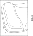
- FIG. 10 shows the headrest assembly 100 mounted to the front of a backrest of an aircraft passenger seat 128, and shows the headrest assembly 100 in the fully stowed condition.
- FIG. 11 shows the mounted headrest assembly 100 in the fully deployed condition forming a cup shape that envelopes the user's head.
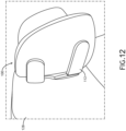
- FIG. 12 shows the mounted headrest assembly 100 from the side and in the fully deployed condition illustrating the longer length of the lower lateral arms 112 providing support for the cheeks and jaw, as well as privacy for the user.
Landscapes
- Engineering & Computer Science (AREA)
- Aviation & Aerospace Engineering (AREA)
- Transportation (AREA)
- Mechanical Engineering (AREA)
- Chair Legs, Seat Parts, And Backrests (AREA)
Abstract
An adjustable headrest (100) for a seat (128) such as an aircraft passenger seat. In embodiments, the headrest includes an adjustment subassembly (104) including a plurality of independently adjustable lateral support arms (112). Each support arm includes at least one articulating segment (114). A cushion subassembly (106) is mounted to the adjustment subassembly by way of slidable couplings to prevent puckering in the cushion subassembly when the lateral arms are adjusted forward. In embodiments, the lateral support arms are grouped into upper and lower pairs of lateral arms wherein the lateral arms in the lower pair have a longer length as compared to the lateral arms in the upper pair to support the cheek and jaw of a user.
Description
- The present disclosure relates generally to an adjustable headrest, and more particularly, to a headrest assembly including an adjustment subassembly providing a highly configurable support provision for the sides of the head.
- Seats such as aircraft passenger seats are designed for safety and comfort. Safety typically pertains to the seat frame construction and material performance, while comfort typically pertains to the seat adjustability, ergonomics, cushioning, and climatization.
- Headrests are one example of a seat element that provides both comfort and support. For example, a seat may include a separate headrest that serves to center the head with respect to the backrest, provide additional cushioning, and in some cases include a provision for sleeping. While some headrests may be adjustable depending on the user and user preference, adjustability is typically limited to height and/or tilt. In addition, conventional headrests are not able to achieve a 'cupping' shape considering fixed attachments of the cushion to the underlying support structure.
- Therefore, what is needed is a headrest with a provision of support that is more configurable to the side of the head, as well as providing an enveloping experience for the user.
- In one aspect, embodiments of the inventive concepts disclosed herein are directed to a headrest assembly including a fixed base mountable to a seat, an adjustment subassembly, and a cushion subassembly slidably coupled to the adjustment assembly. In embodiments, the adjustment subassembly includes an adjustable base movably mounted to the fixed base configured for up and down adjustment, and a plurality of lateral arms extending from the adjustable base, each arm including a segment rotatably connected to the adjustable base, and each lateral arm configured for independent forward and back adjustment. In embodiments, the cushion assembly includes a flexible cushion, and a plurality of supports slidably coupling the flexible cushion to the adjustment subassembly, each support having one end slidably engaging one of the segments.
- In some embodiments, the cushion subassembly further includes additional supports each having one end slidably engaging the adjustable base.
- In some embodiments, the adjustment subassembly includes four lateral arms.
- In some embodiments, two of the four lateral arms extend laterally from a left side of the adjustable base, two of the four lateral arms extend laterally from a right side of the adjustable base, and the four lateral arms are symmetrical about a vertical line drawn through the adjustable base.
- In some embodiments, two of the four lateral arms extend laterally from a left side of the adjustable base, two of the four lateral arms extend laterally from a right side of the adjustable base, and the four lateral arms are asymmetrical about a horizontal line drawn through the adjustable base.
- In some embodiments, the four lateral arms are grouped into an upper pair of lateral arms and a lower pair of lateral arms, the upper pair of lateral arms are aligned along a substantially horizontal axis, and the lower pair of lateral arms are angled relative to the substantially horizontal axis.
- In some embodiments, two of the four lateral arms, one positioned on each side of the adjustable base, each include an additional segment rotatably attached to their respective segment, and the support associated with each of the two of the four lateral arms slidably engages the additional segment.
- In some embodiments, the lateral arms including the additional segment are longer than the lateral arms without the additional segment.
- In some embodiments, the four lateral arms are arranged to form an X-shape.
- In some embodiments, each of the lateral arms is independently adjustable between a stowed position substantially aligned with a curvature of the adjustable base, and a deployed position forward of and angled relative to the curvature of the adjustable base.
- In some embodiments, the cushion subassembly includes relief cuts in the flexible cushion positioned proximal to the rotatable connections of the segments.
- In some embodiments, the adjustment subassembly has a larger radius and lower curvature when the plurality of lateral arms are stowed as compared to when the plurality of lateral arms are deployed forward.
- According to another aspect, embodiments of the inventive concepts disclosed herein are directed to an aircraft passenger seat including a backrest and a headrest assembly as provided above.
- This summary is provided solely as an introduction to subject matter that is fully described in the following detailed description and drawing figures. This summary should not be considered to describe essential features nor be used to determine the scope of the claims. Moreover, it is to be understood that both the foregoing summary and the following detailed description are explanatory only and are not necessarily restrictive of the subject matter claimed.
- Implementations of the inventive concepts disclosed herein may be better understood when consideration is given to the following detailed description thereof. Such description refers to the included drawings, which are not necessarily to scale, and in which some features may be exaggerated and some features may be omitted or may be represented schematically in the interest of clarity. Like reference numerals in the drawings may represent and refer to the same or similar element, feature, or function. In the drawings:
-
FIG. 1 is a front perspective view of a headrest assembly, in accordance with example embodiments of this disclosure; -
FIG. 2 is a rear perspective view of the headrest assembly shown inFIG. 1 ; -
FIG. 3 is a top view of the headrest assembly shown inFIG. 1 ; -
FIG. 4 is a bottom view of the headrest assembly shown inFIG. 1 ; -
FIG. 5 is a front view of the headrest assembly shown inFIG. 1 ; -
FIG. 6 is a back view of the headrest assembly shown inFIG. 1 ; -
FIG. 7 is a right side view of the headrest assembly shown inFIG. 1 ; -
FIG. 8 is a left side view of the headrest assembly shown inFIG. 1 ; -
FIG. 9 is a front perspective view of the headrest assembly showing the cushion subassembly in transparency to illustrate the adjustment subassembly; -
FIG. 10 is a fragmentary front perspective view showing the headrest assembly installed on a passenger seat, in accordance with example embodiments of this disclosure; -
FIG. 11 shows the headrest assembly in a deployed condition; and -
FIG. 12 shows the headrest assembly in a fully deployed condition. - Before explaining at least one embodiment of the inventive concepts disclosed herein in detail, it is to be understood that the inventive concepts are not limited in their application to the details of construction and the arrangement of the components or steps or methodologies set forth in the following description or illustrated in the drawings. In the following detailed description of embodiments of the instant inventive concepts, numerous specific details are set forth in order to provide a more thorough understanding of the inventive concepts. However, it will be apparent to one of ordinary skill in the art having the benefit of the instant disclosure that the inventive concepts disclosed herein may be practiced without these specific details. In other instances, well-known features may not be described in detail to avoid unnecessarily complicating the instant disclosure. The inventive concepts disclosed herein are capable of other embodiments or of being practiced or carried out in various ways. Also, it is to be understood that the phraseology and terminology employed herein is for the purpose of description and should not be regarded as limiting.
- As used herein, a letter following a reference numeral is intended to reference an embodiment of the feature or element that may be similar, but not necessarily identical, to a previously described element or feature bearing the same reference numeral (e.g., 1, 1a, 1b). Such shorthand notations are used for purposes of convenience only, and should not be construed to limit the inventive concepts disclosed herein in any way unless expressly stated to the contrary.
- Further, unless expressly stated to the contrary, "or" refers to an inclusive or and not to an exclusive or. For example, a condition A or B is satisfied by anyone of the following: A is true (or present) and B is false (or not present), A is false (or not present) and B is true (or present), and both A and B are true (or present).
- In addition, use of the "a" or "an" are employed to describe elements and components of embodiments of the instant inventive concepts. This is done merely for convenience and to give a general sense of the inventive concepts, and "a" and "an" are intended to include one or at least one and the singular also includes the plural unless it is obvious that it is meant otherwise.
- Finally, as used herein any reference to "one embodiment" or "some embodiments" means that a particular element, feature, structure, or characteristic described in connection with the embodiment is included in at least one embodiment of the inventive concepts disclosed herein. The appearances of the phrase "in some embodiments" in various places in the specification are not necessarily all referring to the same embodiment, and embodiments of the inventive concepts disclosed may include one or more of the features expressly described or inherently present herein, or any combination of sub-combination of two or more such features, along with any other features which may not necessarily be expressly described or inherently present in the instant disclosure.
- Broadly, embodiments of the inventive concepts disclosed herein are directed to a highly adjustable headrest assembly. In use, the headrest may be adjusted up and down, as well as portions of the headrest are adjustable forward and back. Portions of the headrest are independently adjustable to maximize configurability for the user. The cushion component of the headrest is slidably coupled to the adjustment component of the headrest to facilitate maximum cushion shape change without resistance and puckering in the flexible cushion component. In a non-limiting application, the headrest assembly may be utilized on an aircraft passenger seat to facilitate greater comfort on long range and premium sectors through the provision of support that is more configurable to the side of the head and provides an enveloping experience for the user.
-
FIGS. 1-8 illustrate various perspective, front, back, top, side, etc. views of theheadrest assembly 100 according to embodiments of the present disclosure. Theheadrest assembly 100 generally includes a fixedbase 102 for mounting to a seat, anadjustment subassembly 104 movably coupled to the fixedbase 102, and acushion subassembly 106 slidably coupled to theadjustment subassembly 104. In use, theadjustment subassembly 104 interacts with the fixedbase 102 to change the vertical position of the headrest, and theadjustment subassembly 104 interacts with thecushion subassembly 106 to change the shape of the attached cushion. In embodiments, the adjustment capability of the headrest up and down is separate from the adjustment capability of the headrest forward and back. As such, various combinations of adjustments can be used to configure the headrest assembly according to the physical dimensions and/or preference of the user. -
FIGS. 2 and6 best illustrate the fixedbase 102. The term 'fixed' as used herein means fixed relative to the other components of the headrest assembly, and not necessarily fixed in relation to the seat. In embodiments, the fixedbase 102 may be attached to a front of a seat backrest using a plurality of fasteners receivable through the fixedbase 102 and into backrest structure. Theadjustment subassembly 104 generally includes anadjustable base 108 movably mounted to the fixedbase 102. In some embodiments, theadjustable base 108 is slidably coupled to the fixedbase 102, for instance configured to slide up and down by way of a slide mechanism or guiderollers 110 as shown inFIG. 4 . Theadjustable base 108 may be implemented as a mounting plate. As shown inFIG. 3 , theadjustable base 108 may have a subtle curvature that induces the same or similar curvature in thecushion subassembly 106. - In embodiments, the
cushion subassembly 106 includes a cushion. The cushion may be positioned beneath a cover. The cushion is flexible in order to move with the movements of theadjustment subassembly 104. In embodiments, the cushion subassembly may include relief cuts positioned on the backside thereof proximal to the joints of the components of theadjustment subassembly 104. The relief cuts allow the cushion to bend to conform to the shape of theadjustment subassembly 104. -
FIG. 9 illustrates theheadrest assembly 100 with thecushion subassembly 106 shown transparent to reveal theadjustment subassembly 104. Theadjustment subassembly 104 generally includes theadjustable base 108 and a plurality oflateral arms 112 extending outwardly from theadjustable base 108. Eachlateral arm 112 includes asegment 114 rotatably connected to theadjustable base 108. Eachsegment 114 is independently adjustable by rotating thesegment 114, by hand, forward and away from the seat toward a deployed condition of the lateral arm, and backward toward the seat toward a stowed condition of the lateral arm. Friction hinges may be used for the rotational attachments.FIGS. 1-9 show each of thelateral arms 112 fully stowed to provide a substantially flat headrest or a headrest with a minimum curvature. - As best shown in
FIGS. 6 and9 , theadjustment subassembly 104 includes fourlateral arms 112. Two of the fourlateral arms 112 extend laterally from a left side of theadjustable base 108, and two of the fourlateral arms 112 extend laterally from a right side of theadjustable base 108. In embodiments, the fourlateral arms 112 may be symmetrical about avertical line 116 drawn through theadjustable base 108, and the fourlateral arms 112 may be asymmetrical about ahorizontal line 118 drawn through theadjustable base 108. - In embodiments, the four
lateral arms 112 may be grouped into an upper pair of lateral arms corresponding to an upper head support portion (e.g., temple region), and a lower pair of lateral arms corresponding to a lower head support portion (e.g., cheek and jaw), wherein the upper pair of lateral arms are aligned along a substantially horizontal axis, and the lower pair of lateral arms are angled relative to the substantially horizontal axis. In embodiments, thelateral arms 112 on each side of theadjustable base 108 may diverge in a direction away from theadjustable base 108, and converge in a direction toward theadjustable base 108. In embodiments, the fourlateral arms 112 may be arranged to form an X-shape. In embodiments, eachlateral arm 112 is independently adjustable between a stowed position substantially aligned with the curvature of theadjustable base 108, and a deployed position forward of and angled relative to theadjustable base 108. - In embodiments, two of the four
lateral arms 112, for instance the lowerlateral arms 112 positioned on each side of theadjustable base 108, further include anadditional segment 120 rotatably attached to theirrespective segment 114. Theadditional segments 120 lengthen and increase the adjustability of the lowerlateral arms 112, such that the lowerlateral arms 112 have a comparatively longer length than the upperlateral arms 112. This configuration provides for better support of the cheek and jaw of the head when thelateral arms 112 are deployed fully forward. Additional segments may be added to any of thelateral arms 112 to increase the arm length and/or articulating ability of the arms. For example, the length of the individual segments may be shortened and the number of segments increased to decrease the radius of curvature of a fully deployedlateral arm 112. - With continued reference to
FIG. 9 , thecushion subassembly 106 further includes a plurality ofsupports 122 configured to slidably couple thecushion subassembly 106 to theadjustment subassembly 104. In some embodiments, thesupports 122 may be part of theadjustment assembly 104 and configured for attachment to thecushion subassembly 106. In embodiments, eachsupport 122 includes a first end mounted to or positioned within the cushion, and a second end slidably engaging one of thesegments 114. As shown, the upperlateral arms 112 slidably engage thesegments 114 rotatably coupled to theadjustable base 108, and the lowerlateral arms 112 slidably engage theadditional segments 120 coupled to thesegments 114. In embodiments, eachsegment support 122 may include alinear slot 124 defining a motion path for therespective support 122. - In use, the
supports 122 travel along theirrespective slot 124 to accommodate movements in the cushion that would otherwise cause puckering, bunching, folding, etc. with the use of fixed attachment points. For example, with the sliding couplings, when alateral arm 112 is articulated fully forward therespective support 122 may travel to one end of the slot, and when thelateral arm 112 is return to fully stowed therespective support 122 may travel to the opposing end of the slot. In embodiments, thecushion subassembly 106 may further includeadditional supports 126 each having one end slidably engaging theadjustable base 106 to accommodate vertical adjustment of thecushion subassembly 106 relative to theadjustment subassembly 104. - The number of lateral arms, arm angles, arm lengths, number of additional segments, segment lengths, slot lengths, and slot angles may be customized to change the headrest adjustability performance.
-
FIG. 10 shows theheadrest assembly 100 mounted to the front of a backrest of anaircraft passenger seat 128, and shows theheadrest assembly 100 in the fully stowed condition.FIG. 11 shows the mountedheadrest assembly 100 in the fully deployed condition forming a cup shape that envelopes the user's head.FIG. 12 shows the mountedheadrest assembly 100 from the side and in the fully deployed condition illustrating the longer length of the lowerlateral arms 112 providing support for the cheeks and jaw, as well as privacy for the user. - From the above description, it is clear that the inventive concepts disclosed herein are well adapted to achieve the objectives and to attain the advantages mentioned herein as well as those inherent in the inventive concepts disclosed herein. While presently preferred embodiments of the inventive concepts disclosed herein have been described for purposes of this disclosure, it will be understood that numerous changes may be made within the scope of the invention as defined by the claims.
Claims (13)
- A headrest assembly (100), comprising:a fixed base (102) mountable to a seat;an adjustment subassembly (104) comprising:an adjustable base (108) movably mounted to the fixed base, the adjustable base configured for up and down adjustment; anda plurality of lateral arms (112) extending from the adjustable base, each lateral arm including a segment (114) rotatably connected to the adjustable base, and each lateral arm configured for independent forward and back adjustment; anda cushion subassembly (106) comprising:a flexible cushion; anda plurality of supports (122) slidably coupling the flexible cushion to the adjustment subassembly, each support having one end slidably engaging one of the segments.
- The headrest assembly (100) according to claim 1, wherein the cushion subassembly (106) further comprises additional supports (126) each having one end slidably engaging the adjustable base (108).
- The headrest assembly (100) according to claim 1 or 2, wherein the adjustment subassembly (104) comprises four lateral arms (112).
- The headrest assembly (100) according to claim 3, wherein:two of the four lateral arms (112) extend laterally from a left side of the adjustable base (108);two of the four lateral arms (112) extend laterally from a right side of the adjustable base (108); andthe four lateral arms (112) are symmetrical about a vertical line (116) drawn through the adjustable base (108).
- The headrest assembly (100) according to claim 3, wherein:two of the four lateral arms (112) extend laterally from a left side of the adjustable base (108);two of the four lateral arms (112) extend laterally from a right side of the adjustable base (108); andthe four lateral arms (112) are asymmetrical about a horizontal line (118) drawn through the adjustable base (108).
- The headrest assembly (100) according to claim 3, wherein:the four lateral arms (112) are grouped into an upper pair of lateral arms and a lower pair of lateral arms;the upper pair of lateral arms are aligned along a substantially horizontal axis; andthe lower pair of lateral arms are angled relative to the substantially horizontal axis.
- The headrest assembly (100) according to claim 3, wherein:two of the four lateral arms (112), one positioned on each side of the adjustable base (114), each include an additional segment (120) rotatably attached to their respective segment (114); andthe support (122) associated with each of the two of the four lateral arms slidably engages the additional segment (120).
- The headrest assembly (100) according to claim 7, wherein the lateral arms including the additional segment (120) are longer than the lateral arms without the additional segment.
- The headrest assembly (100) according to claim 3, wherein the four lateral arms (112) are arranged to form an X-shape.
- The headrest assembly (100) according to any preceding claim, wherein each of the lateral arms (112) is independently adjustable between a stowed position substantially aligned with a curvature of the adjustable base (108), and a deployed position forward of and angled relative to the curvature of the adjustable base.
- The headrest assembly (100) according to any preceding claim, wherein the cushion subassembly (106) includes relief cuts in the flexible cushion positioned proximal to the rotatable connections of the segments.
- The headrest assembly (100) according to any preceding claim, wherein the adjustment subassembly (104) has a larger radius and lower curvature when the plurality of lateral arms are stowed as compared to when the plurality of lateral arms are deployed forward.
- An aircraft passenger seat (128), comprising:a backrest, anda headrest assembly (100) according to any one of claims 1 to 12, wherein the headrest assembly is mounted to the backrest.
Applications Claiming Priority (1)
| Application Number | Priority Date | Filing Date | Title |
|---|---|---|---|
| US18/381,428 US20250128819A1 (en) | 2023-10-18 | 2023-10-18 | Headrest with independently adjustable arms and flexible cushion |
Publications (1)
| Publication Number | Publication Date |
|---|---|
| EP4541655A1 true EP4541655A1 (en) | 2025-04-23 |
Family
ID=93212016
Family Applications (1)
| Application Number | Title | Priority Date | Filing Date |
|---|---|---|---|
| EP24207596.8A Pending EP4541655A1 (en) | 2023-10-18 | 2024-10-18 | Headrest with independently adjustable arms and flexible cushion |
Country Status (2)
| Country | Link |
|---|---|
| US (1) | US20250128819A1 (en) |
| EP (1) | EP4541655A1 (en) |
Citations (4)
| Publication number | Priority date | Publication date | Assignee | Title |
|---|---|---|---|---|
| US20040007910A1 (en) * | 2002-07-12 | 2004-01-15 | Skelly Trevor B. | Headrest mounting plate, seat headrest, and passenger seat with headrest |
| US20160023767A1 (en) * | 2013-04-08 | 2016-01-28 | Singapore Technologies Aerospace Ltd | Headrest structure, headrest cushion and passenger seat |
| EP3822167A1 (en) * | 2019-11-15 | 2021-05-19 | B/E Aerospace, Inc. | Staggered pneumatic articulation system for seat back deployment and comfort |
| US20220063466A1 (en) * | 2019-01-15 | 2022-03-03 | Ayhan ÍLKER | Angle mechanism passenger seat sleeping pillow |
Family Cites Families (1)
| Publication number | Priority date | Publication date | Assignee | Title |
|---|---|---|---|---|
| US7264313B2 (en) * | 2000-09-20 | 2007-09-04 | Robert Clough | Seat headrest |
-
2023
- 2023-10-18 US US18/381,428 patent/US20250128819A1/en active Pending
-
2024
- 2024-10-18 EP EP24207596.8A patent/EP4541655A1/en active Pending
Patent Citations (4)
| Publication number | Priority date | Publication date | Assignee | Title |
|---|---|---|---|---|
| US20040007910A1 (en) * | 2002-07-12 | 2004-01-15 | Skelly Trevor B. | Headrest mounting plate, seat headrest, and passenger seat with headrest |
| US20160023767A1 (en) * | 2013-04-08 | 2016-01-28 | Singapore Technologies Aerospace Ltd | Headrest structure, headrest cushion and passenger seat |
| US20220063466A1 (en) * | 2019-01-15 | 2022-03-03 | Ayhan ÍLKER | Angle mechanism passenger seat sleeping pillow |
| EP3822167A1 (en) * | 2019-11-15 | 2021-05-19 | B/E Aerospace, Inc. | Staggered pneumatic articulation system for seat back deployment and comfort |
Also Published As
| Publication number | Publication date |
|---|---|
| US20250128819A1 (en) | 2025-04-24 |
Similar Documents
| Publication | Publication Date | Title |
|---|---|---|
| CN110091995B (en) | Work-dining aircraft seat with tilt and shift articulation | |
| RU147472U1 (en) | ARMCHAIR FOR A VEHICLE WITH HINGE HEADREST | |
| US9486079B2 (en) | Chair with seat depth adjustment and back support | |
| EP3271247B1 (en) | Passenger seat headrest | |
| CN105799555B (en) | Manual independent thigh extension | |
| US10035442B2 (en) | Adjustable upper seatback module | |
| US9809131B2 (en) | Anthropomorphic pivotable upper seatback support | |
| US7159934B2 (en) | Vehicle seat and head restraint assembly | |
| JP6404902B2 (en) | Headrest structure, headrest cushion and passenger seat | |
| EP1670337A2 (en) | Headrest support assembly | |
| US10676002B2 (en) | Vehicle seat with cantilevered headrest assembly and positioning system | |
| EP3702282A1 (en) | Multi-position adjustable headrest assembly | |
| US10897997B2 (en) | Armchair comprising an adjustable headrest | |
| EP4541655A1 (en) | Headrest with independently adjustable arms and flexible cushion | |
| EP3976472B1 (en) | Passenger seat with non-intrusive recline | |
| CN114954183A (en) | Trim assembly for a vehicle seat assembly | |
| EP1618816B1 (en) | Portable backrest structure | |
| EP4541656A1 (en) | Headrest with deployable oblique supports | |
| EP4541654A1 (en) | Seat for vehicle, and vehicle | |
| KR102362526B1 (en) | Neck Support HeadRest | |
| KR102576299B1 (en) | Relaxation Headrest | |
| EP3762255B1 (en) | Headrest for a seat | |
| MXPA97009896A (en) | Adjustment adjustment assembly |
Legal Events
| Date | Code | Title | Description |
|---|---|---|---|
| PUAI | Public reference made under article 153(3) epc to a published international application that has entered the european phase |
Free format text: ORIGINAL CODE: 0009012 |
|
| STAA | Information on the status of an ep patent application or granted ep patent |
Free format text: STATUS: THE APPLICATION HAS BEEN PUBLISHED |
|
| AK | Designated contracting states |
Kind code of ref document: A1 Designated state(s): AL AT BE BG CH CY CZ DE DK EE ES FI FR GB GR HR HU IE IS IT LI LT LU LV MC ME MK MT NL NO PL PT RO RS SE SI SK SM TR |
|
| STAA | Information on the status of an ep patent application or granted ep patent |
Free format text: STATUS: REQUEST FOR EXAMINATION WAS MADE |
|
| 17P | Request for examination filed |
Effective date: 20251023 |