EP4541609A1 - Transport vehicle in general with a load balancing system - Google Patents
Transport vehicle in general with a load balancing system Download PDFInfo
- Publication number
- EP4541609A1 EP4541609A1 EP24205974.9A EP24205974A EP4541609A1 EP 4541609 A1 EP4541609 A1 EP 4541609A1 EP 24205974 A EP24205974 A EP 24205974A EP 4541609 A1 EP4541609 A1 EP 4541609A1
- Authority
- EP
- European Patent Office
- Prior art keywords
- platform
- wheels
- axle
- rods
- vehicle
- Prior art date
- Legal status (The legal status is an assumption and is not a legal conclusion. Google has not performed a legal analysis and makes no representation as to the accuracy of the status listed.)
- Granted
Links
Images




Classifications
-
- B—PERFORMING OPERATIONS; TRANSPORTING
- B60—VEHICLES IN GENERAL
- B60G—VEHICLE SUSPENSION ARRANGEMENTS
- B60G9/00—Resilient suspensions of a rigid axle or axle housing for two or more wheels
-
- B—PERFORMING OPERATIONS; TRANSPORTING
- B60—VEHICLES IN GENERAL
- B60G—VEHICLE SUSPENSION ARRANGEMENTS
- B60G2200/00—Indexing codes relating to suspension types
- B60G2200/30—Rigid axle suspensions
- B60G2200/34—Stabilising mechanisms, e.g. for lateral stability
-
- B—PERFORMING OPERATIONS; TRANSPORTING
- B60—VEHICLES IN GENERAL
- B60G—VEHICLE SUSPENSION ARRANGEMENTS
- B60G2204/00—Indexing codes related to suspensions per se or to auxiliary parts
- B60G2204/40—Auxiliary suspension parts; Adjustment of suspensions
- B60G2204/421—Pivoted lever mechanisms for mounting suspension elements, e.g. Watt linkage
-
- B—PERFORMING OPERATIONS; TRANSPORTING
- B60—VEHICLES IN GENERAL
- B60G—VEHICLE SUSPENSION ARRANGEMENTS
- B60G2206/00—Indexing codes related to the manufacturing of suspensions: constructional features, the materials used, procedures or tools
- B60G2206/01—Constructional features of suspension elements, e.g. arms, dampers, springs
- B60G2206/10—Constructional features of arms
- B60G2206/11—Constructional features of arms the arm being a radius or track or torque or steering rod or stabiliser end link
- B60G2206/111—Constructional features of arms the arm being a radius or track or torque or steering rod or stabiliser end link of adjustable length
- B60G2206/1114—Self-adjustable during driving
-
- B—PERFORMING OPERATIONS; TRANSPORTING
- B60—VEHICLES IN GENERAL
- B60G—VEHICLE SUSPENSION ARRANGEMENTS
- B60G2300/00—Indexing codes relating to the type of vehicle
- B60G2300/04—Trailers
- B60G2300/042—Semi-trailers
Definitions
- the present invention concerns transport vehicle in general, provided with a new system for balancing loads on the platform of the aforesaid transport vehicle.
- the field of the invention is that of equipment that is employed to prevent loads positioned on coaches, semi-trailer trucks and other means of transport in general, from causing unbalancing thereof when the trajectory varies, for example on a curve, when braking, or simply due to incorrect positioning of the load on the platform of the vehicle.
- JP H10 315729 A concerns a lateral control structure of a vehicle with spring suspension.
- the main object of the present invention is to provide a vehicle with an improved system for supporting loads on the platform which, compared to similar equipment of the prior art, is able to prevent phenomena of unbalancing of the loads.
- the vehicle according to the present invention offers the advantage of transforming the tilt of the platform into a lowering movement thereof or a movement towards the axle of the wheels, preserving the desired horizontal alignment even when the vehicle travels around curves.
- the invention offers the important advantage of overcoming the risks of overturning of the means of transport due to unbalancing of the loads. Moreover, the vehicle of the invention also achieves the advantage of reduced and more even consumption of the tyres, of the brakes, of the shock absorbers and of other parts.
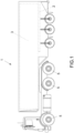
- the transport vehicle 1 illustrated in Fig. 1 is a semi-trailer truck, on the platform 2 of which a load 3 is placed.
- the platform 2 is conventionally supported on the axle 4 of the wheels 5 by means of respective leaf springs 6 ( Fig. 2 ).
- the platform 2 when the vehicle 1 travels around a curve or on a stretch of road on a slope, or has a load 3 arranged in an unbalanced position, the platform 2 tends to tilt in the direction of the arrow F1 in Fig. 2 , tilting by an angle ⁇ relative to the axle 4 of the wheels 5, compressing in the direction of the arrow F2 the wheel subject to the greatest unbalancing load.
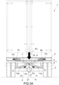
- the vehicle of the invention comprises the load balancing system illustrated in Figs. 3 and 3A .
- the aforesaid system comprises two rods 7 and 8 arranged crossed over in an X-shaped scissor-like configuration and mutually pivoted, on their crossing point, at a pin 9.
- This pin 9 is in turn fixed to a bracket 10, arranged integral with the platform 2 of the vehicle 1, at the axis A perpendicular to the axles 4 of the front and rear wheels 5 and which passes through the joining line of the respective half-axles, i.e., passing through the differential 21.
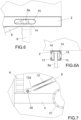
- each rod 7 and 8 has a telescoping structure, carrying bars 11 and 12, respectively, housed sliding inside them ( Figs. 3 and 7 ).
- the upper ends 7a and 8a of the rods 7,8 engage sliding inside respective tracks 13 of the platform 2, by means of bearings, bushings 14 and the like ( Fig. 6A ). Slots 15 are also provided on this platform to allow inspection and access to the described system of tracks 13 and of bearings 14 ( Fig. 6 ).
- the lower ends 11a and 12a of the sliding bars 11 and 12 of the rods 7 and 8 are instead pivoted on the axle 4 of the wheels 5, at respective pins 20 ( Fig. 7 ).
- the aforesaid rods can be of any geometric shape and made of a material suitable to support the load.
- the bars 11, 12 are caused to slide inside the respective rods 7,8 in the direction of the arrows F4 in Fig. 3A , thereby allowing lowering of the platform 2 in the direction of the arrow F5.
- the assembly of tracks 13 and bearings 14 is no longer arranged on the platform 2, but on the axle 4 of the wheels 5, receiving in this position the upper ends 7a, 8a of the rods 7 and 8, the pivot pin 19 of which is fixed to a bracket 16 of the axle 4 of the wheels.
- the bracket 16 is arranged at the axis A perpendicular to the axles 4 of the front and rear wheels 5, and which passes through the joining line of the respective half-axles, i.e., passing through the differential 21.
- the system of the vehicle of the invention comprises rods 17 and 18, arranged crossed over in a scissor-like arrangement at a pin 19 integral with the bracket 16 of the axle 4 of the wheels 5.
- the arrangement of the bracket 16 and coupling of the ends 17a, 17b, 18a, 18b of the rods 17, 18 on the platform 2 of the vehicle 1 and on the axle 4 of the wheels 5 is the same as described with reference to Figs. 4 , 4A , 6 and 6A .
- the system of the vehicle of the invention is suitable to be mounted on one or more axles of the wheels of the vehicle illustrated, for example, in Fig. 1 , depending on the distribution of the load on the platform 2.
Landscapes
- Engineering & Computer Science (AREA)
- Mechanical Engineering (AREA)
- Handcart (AREA)
- Vehicle Body Suspensions (AREA)
Abstract
Description
- The present invention concerns transport vehicle in general, provided with a new system for balancing loads on the platform of the aforesaid transport vehicle.
- The field of the invention is that of equipment that is employed to prevent loads positioned on coaches, semi-trailer trucks and other means of transport in general, from causing unbalancing thereof when the trajectory varies, for example on a curve, when braking, or simply due to incorrect positioning of the load on the platform of the vehicle.
- The systems currently employed for this purpose use stabilizer bars, which however only minimally offset phenomena of unbalanced loads, always leaving a residual tilt angle, relative to the axle of the wheels, of the platform that supports it.
- The publication
JP H10 315729 A - The
publication US 2 755 100 A concerns a rear suspension for motor vehicles. - Therefore, the main object of the present invention is to provide a vehicle with an improved system for supporting loads on the platform which, compared to similar equipment of the prior art, is able to prevent phenomena of unbalancing of the loads.
- This and other objects are achieved with the vehicle of
claim 1. Preferred embodiments of the invention appear in the remaining claims. - In comparison with the prior art vehicles, provided with systems used to correct unbalancing of the loads on the platform, the vehicle according to the present invention offers the advantage of transforming the tilt of the platform into a lowering movement thereof or a movement towards the axle of the wheels, preserving the desired horizontal alignment even when the vehicle travels around curves.
- In this way, the invention offers the important advantage of overcoming the risks of overturning of the means of transport due to unbalancing of the loads. Moreover, the vehicle of the invention also achieves the advantage of reduced and more even consumption of the tyres, of the brakes, of the shock absorbers and of other parts.
- These and other objects, advantages and features will be apparent from the following description of some preferred embodiments of the vehicle of the invention, illustrated by way of non-limiting example in the figures of the accompanying drawings,
wherein: -
Figs. 1 and1A illustrate examples di transport vehicles, suitable to be equipped with the system of the invention; -
Fig. 2 illustrates the condition of unbalancing of the platform of a prior art vehicle that is travelling along a stretch of road with a curve; -
Figs. 3 and3A illustrate a first embodiment of the vehicle of the invention, with balancing system in a condition at rest and of unbalanced load while travelling around a curve, respectively; -
Figs. 4 and4A illustrate a second embodiment of the vehicle of the invention, with balancing system in a condition at rest and of unbalanced load while travelling around a curve, respectively; -
Figs. 5 and5A illustrate a third embodiment of the vehicle of the invention, with balancing system in a condition at rest and of unbalanced load while travelling around a curve, respectively; -
Figs. 6 and 6A illustrate, in a front view and in a side view respectively, the detail of the housing of the ends of the rods of the balancing system of the vehicle according to the invention on the loading platform or on the axle of the wheels of the means of transport inFig. 1 ; and -
Fig. 7 illustrates in a front view the detail of the pin for coupling the ends of the rods of the balancing system of the vehicle of the invention to the axle of the wheels of the means of transport illustrated inFig. 1 . - The
transport vehicle 1 illustrated inFig. 1 is a semi-trailer truck, on theplatform 2 of which aload 3 is placed. In turn, theplatform 2 is conventionally supported on theaxle 4 of thewheels 5 by means of respective leaf springs 6 (Fig. 2 ). - In a system of this type, when the
vehicle 1 travels around a curve or on a stretch of road on a slope, or has aload 3 arranged in an unbalanced position, theplatform 2 tends to tilt in the direction of the arrow F1 inFig. 2 , tilting by an angle α relative to theaxle 4 of thewheels 5, compressing in the direction of the arrow F2 the wheel subject to the greatest unbalancing load. - In these conditions there are evident risks of the vehicle overturning and, in any case, there is increased wear of parts (tyres, brakes, bearings and other parts) subject to the greatest load F2.
- To overcome these drawbacks, the vehicle of the invention comprises the load balancing system illustrated in
Figs. 3 and3A . The aforesaid system comprises tworods pin 9. Thispin 9 is in turn fixed to abracket 10, arranged integral with theplatform 2 of thevehicle 1, at the axis A perpendicular to theaxles 4 of the front andrear wheels 5 and which passes through the joining line of the respective half-axles, i.e., passing through thedifferential 21. In particular, eachrod bars Figs. 3 and7 ). - The
upper ends rods respective tracks 13 of theplatform 2, by means of bearings,bushings 14 and the like (Fig. 6A ).Slots 15 are also provided on this platform to allow inspection and access to the described system oftracks 13 and of bearings 14 (Fig. 6 ). - The
lower ends sliding bars rods axle 4 of thewheels 5, at respective pins 20 (Fig. 7 ). - The aforesaid rods can be of any geometric shape and made of a material suitable to support the load.
- With the system of the vehicle of the invention, and as better represented in
Fig. 3A , when there is an unbalancing of theload 3 in the direction of the arrow F2, theupper ends rods respective tracks 13 of the platform 2 (arrows F3 inFig. 3A ). - For their part, the
bars respective rods Fig. 3A , thereby allowing lowering of theplatform 2 in the direction of the arrow F5. - By comparing the above-described
Figs. 3 and3A , it can be observed how, in the presence of an unbalanced load, the initial distance H between theplatform 2 and theaxle 4 of thewheels 5 is taken to a smaller distance h, while preserving the condition of parallelism between the platform and the axle of the front andrear wheels 5. - In the variant illustrated in
Figs. 4 and4A , the assembly oftracks 13 andbearings 14 is no longer arranged on theplatform 2, but on theaxle 4 of thewheels 5, receiving in this position theupper ends rods pivot pin 19 of which is fixed to abracket 16 of theaxle 4 of the wheels. - Also in this embodiment, the
bracket 16 is arranged at the axis A perpendicular to theaxles 4 of the front andrear wheels 5, and which passes through the joining line of the respective half-axles, i.e., passing through thedifferential 21. - For their part, the
lower ends sliding bars rods platform 2, maintaining the arrangement represented inFig. 7 . - In the variant of
Figs. 5 and5A , the system of the vehicle of the invention comprisesrods pin 19 integral with thebracket 16 of theaxle 4 of thewheels 5. The arrangement of thebracket 16 and coupling of theends rods platform 2 of thevehicle 1 and on theaxle 4 of thewheels 5 is the same as described with reference toFigs. 4 ,4A ,6 and 6A . - The system of the vehicle of the invention is suitable to be mounted on one or more axles of the wheels of the vehicle illustrated, for example, in
Fig. 1 , depending on the distribution of the load on theplatform 2. - The invention, as described above and illustrated in the accompanying figures, is susceptible to modifications to produce further variants, in any case falling within the scope of the claims below. Thus, for example, the
sliding bars axle 4 of the wheels, and to theplatform 2 of thevehicle 1.
Claims (7)
- A transport vehicle provided with a system for balancing loads on the platform of said vehicle, characterized in that said system comprises two rods (7,8;17,18) mutually crossed over in an X-shaped scissor-like configuration and pivoted, on the crossing point, to a pin (9,19) fixed to the platform (2) or to the axle (4) of the wheels (5) of said vehicle (1), at a bracket (10) integral with said platform (2) or at a bracket (16) integral with the axle (4) of the wheels (5), wherein said brackets (10,16) are arranged at the axis (A) perpendicular to the axles (4) of the wheels (5) and which passes through the joining line of the respective half-axles, i.e., passing through the differential (21), wherein the ends of said rods (7,8;17,18) are mounted sliding and/or rotating on said platform (2) and on the axle (4) of the wheels (5).
- The vehicle according to claim 1, characterized in that said rods (7,8) have a telescoping structure, equipped with bars (11,12) arranged sliding inside the rods (7,8).
- The vehicle according to claim 2, characterized in that said rods (7,8) are mutually pivoted on said pin (9) fixed to the aforesaid bracket (10) of said platform (2), wherein the upper ends (7a,8a) of said rods (7,8) engage sliding inside respective tracks (13) of the platform (2), and in that the lower ends (11a,12a) of said sliding bars (11,12) are arranged pivoted on the axle (4) of the wheels (5).
- The vehicle according to claim 2, characterized in that said rods (7,8) are mutually pivoted on said pin (19) fixed to the aforesaid bracket (16) of the axle (4) of the wheels (5), wherein the lower ends (7a,8a) of said rods (7,8) engage sliding inside respective tracks (13) of the axle (4) and in that the upper ends (11a, 12a) of said sliding bars (11,12) are arranged pivoted on the aforesaid platform (2).
- The vehicle according to claim 1, characterized in that said rods (17,18) are arranged crossed over in an X-shaped scissor-like configuration at said pin (19) integral with the aforesaid bracket (16) of the axle (4) of the wheels (5) of the vehicle (1), wherein the ends (17a,17b,18a,18b) of said rods (17,18) are arranged sliding inside tracks (13) of said platform (2) and of the axle (4) of the wheels (5).
- The vehicle according to one or more of the preceding claims, characterized in that said load balancing system is provided with bearings or bushings (14) for sliding engagement of said ends of the rods (7,8; 17,18) on the platform (2) and on the axle (4) of the wheels (3) of the vehicle (1).
- The vehicle according to claim 6, characterized in that the platform (2) and/or the axle (4) of the wheels (5) is provided with slots (15) for access to the aforesaid assembly of tracks (13) and bearings (14).
Applications Claiming Priority (1)
| Application Number | Priority Date | Filing Date | Title |
|---|---|---|---|
| IT102023000021480A IT202300021480A1 (en) | 2023-10-16 | 2023-10-16 | LOAD BALANCING SYSTEM ON THE PLATFORMS OF GENERAL TRANSPORT MEANS |
Publications (3)
| Publication Number | Publication Date |
|---|---|
| EP4541609A1 true EP4541609A1 (en) | 2025-04-23 |
| EP4541609B1 EP4541609B1 (en) | 2026-01-14 |
| EP4541609C0 EP4541609C0 (en) | 2026-01-14 |
Family
ID=89321572
Family Applications (1)
| Application Number | Title | Priority Date | Filing Date |
|---|---|---|---|
| EP24205974.9A Active EP4541609B1 (en) | 2023-10-16 | 2024-10-10 | Transport vehicle in general with a load balancing system |
Country Status (2)
| Country | Link |
|---|---|
| EP (1) | EP4541609B1 (en) |
| IT (1) | IT202300021480A1 (en) |
Citations (2)
| Publication number | Priority date | Publication date | Assignee | Title |
|---|---|---|---|---|
| US2755100A (en) | 1949-06-30 | 1956-07-17 | Fiat Spa | Rear suspension for motor vehicles |
| JPH10315729A (en) | 1997-05-15 | 1998-12-02 | Daihatsu Motor Co Ltd | Mounting structure of lateral control rod |
-
2023
- 2023-10-16 IT IT102023000021480A patent/IT202300021480A1/en unknown
-
2024
- 2024-10-10 EP EP24205974.9A patent/EP4541609B1/en active Active
Patent Citations (2)
| Publication number | Priority date | Publication date | Assignee | Title |
|---|---|---|---|---|
| US2755100A (en) | 1949-06-30 | 1956-07-17 | Fiat Spa | Rear suspension for motor vehicles |
| JPH10315729A (en) | 1997-05-15 | 1998-12-02 | Daihatsu Motor Co Ltd | Mounting structure of lateral control rod |
Also Published As
| Publication number | Publication date |
|---|---|
| EP4541609B1 (en) | 2026-01-14 |
| IT202300021480A1 (en) | 2025-04-16 |
| EP4541609C0 (en) | 2026-01-14 |
Similar Documents
| Publication | Publication Date | Title |
|---|---|---|
| US5720489A (en) | Movable subframe for tractor-trailers | |
| US10683046B2 (en) | Tandem lift auxiliary axle assembly | |
| US7198298B2 (en) | Movable subframe for semi-trailers | |
| CN109906156A (en) | Double yoke independence trailer suspensions | |
| US6883813B2 (en) | Independent paddle lift axle suspension system | |
| RU2487018C2 (en) | Stabiliser system for wheel axle suspension, and stabiliser | |
| US8485542B1 (en) | Suspension system for a vehicle | |
| US8220809B2 (en) | Independent parallelogram suspension system | |
| US5845919A (en) | Spring beam suspension system | |
| EP4541609B1 (en) | Transport vehicle in general with a load balancing system | |
| AU2023226741A1 (en) | A tandem wheel assembly for a trailer | |
| US6604756B2 (en) | Tridem axle suspension | |
| NL2013397B1 (en) | Independent wheel suspension with air suspension for a trailer and trailers equipped with it. | |
| ES2894280T3 (en) | Rollover mechanism for road vehicles | |
| US8801011B1 (en) | Articulatable suspension system for a vehicle | |
| US6571903B2 (en) | Heavy duty truck suspension with drive axle | |
| US7390000B2 (en) | Lateral link for vehicle suspension systems | |
| KR102152966B1 (en) | Trailer coupling appratus | |
| US5184842A (en) | Vehicle suspension mechanism | |
| US11951796B2 (en) | Bushing for a suspension and vehicle comprising such a bushing | |
| JP6595294B2 (en) | Suspension device with equalizer mechanism | |
| US3747950A (en) | Shock absorbing wheel suspension | |
| US4813695A (en) | Multi-axle vehicle suspension | |
| RU81126U1 (en) | LEVER SUSPENSION FOR CONTINUOUS AXLE SEMITRAILERS | |
| KR20090062206A (en) | Car Axle Suspension |
Legal Events
| Date | Code | Title | Description |
|---|---|---|---|
| PUAI | Public reference made under article 153(3) epc to a published international application that has entered the european phase |
Free format text: ORIGINAL CODE: 0009012 |
|
| STAA | Information on the status of an ep patent application or granted ep patent |
Free format text: STATUS: THE APPLICATION HAS BEEN PUBLISHED |
|
| AK | Designated contracting states |
Kind code of ref document: A1 Designated state(s): AL AT BE BG CH CY CZ DE DK EE ES FI FR GB GR HR HU IE IS IT LI LT LU LV MC ME MK MT NL NO PL PT RO RS SE SI SK SM TR |
|
| P01 | Opt-out of the competence of the unified patent court (upc) registered |
Free format text: CASE NUMBER: APP_19414/2025 Effective date: 20250423 |
|
| STAA | Information on the status of an ep patent application or granted ep patent |
Free format text: STATUS: REQUEST FOR EXAMINATION WAS MADE |
|
| 17P | Request for examination filed |
Effective date: 20250625 |
|
| GRAP | Despatch of communication of intention to grant a patent |
Free format text: ORIGINAL CODE: EPIDOSNIGR1 |
|
| STAA | Information on the status of an ep patent application or granted ep patent |
Free format text: STATUS: GRANT OF PATENT IS INTENDED |
|
| RIC1 | Information provided on ipc code assigned before grant |
Ipc: B60G 9/00 20060101AFI20250915BHEP Ipc: B60G 13/00 20060101ALI20250915BHEP |
|
| INTG | Intention to grant announced |
Effective date: 20251017 |
|
| GRAS | Grant fee paid |
Free format text: ORIGINAL CODE: EPIDOSNIGR3 |
|
| GRAA | (expected) grant |
Free format text: ORIGINAL CODE: 0009210 |
|
| STAA | Information on the status of an ep patent application or granted ep patent |
Free format text: STATUS: THE PATENT HAS BEEN GRANTED |
|
| AK | Designated contracting states |
Kind code of ref document: B1 Designated state(s): AL AT BE BG CH CY CZ DE DK EE ES FI FR GB GR HR HU IE IS IT LI LT LU LV MC ME MK MT NL NO PL PT RO RS SE SI SK SM TR |
|
| REG | Reference to a national code |
Ref country code: CH Ref legal event code: F10 Free format text: ST27 STATUS EVENT CODE: U-0-0-F10-F00 (AS PROVIDED BY THE NATIONAL OFFICE) Effective date: 20260114 Ref country code: GB Ref legal event code: FG4D |
|
| REG | Reference to a national code |
Ref country code: DE Ref legal event code: R096 Ref document number: 602024002059 Country of ref document: DE |
|
| REG | Reference to a national code |
Ref country code: IE Ref legal event code: FG4D |
|
| U01 | Request for unitary effect filed |
Effective date: 20260119 |
|
| U07 | Unitary effect registered |
Designated state(s): AT BE BG DE DK EE FI FR IT LT LU LV MT NL PT RO SE SI Effective date: 20260122 |
|
| P04 | Withdrawal of opt-out of the competence of the unified patent court (upc) registered |
Free format text: CASE NUMBER: APP_19414_1/2025 Effective date: 20260122 |
|
| PG25 | Lapsed in a contracting state [announced via postgrant information from national office to epo] |
Ref country code: RS Free format text: LAPSE BECAUSE OF FAILURE TO SUBMIT A TRANSLATION OF THE DESCRIPTION OR TO PAY THE FEE WITHIN THE PRESCRIBED TIME-LIMIT Effective date: 20260414 |
|
| PG25 | Lapsed in a contracting state [announced via postgrant information from national office to epo] |
Ref country code: ES Free format text: LAPSE BECAUSE OF FAILURE TO SUBMIT A TRANSLATION OF THE DESCRIPTION OR TO PAY THE FEE WITHIN THE PRESCRIBED TIME-LIMIT Effective date: 20260114 |
|
| PG25 | Lapsed in a contracting state [announced via postgrant information from national office to epo] |
Ref country code: PL Free format text: LAPSE BECAUSE OF FAILURE TO SUBMIT A TRANSLATION OF THE DESCRIPTION OR TO PAY THE FEE WITHIN THE PRESCRIBED TIME-LIMIT Effective date: 20260114 |
|
| PG25 | Lapsed in a contracting state [announced via postgrant information from national office to epo] |
Ref country code: GR Free format text: LAPSE BECAUSE OF FAILURE TO SUBMIT A TRANSLATION OF THE DESCRIPTION OR TO PAY THE FEE WITHIN THE PRESCRIBED TIME-LIMIT Effective date: 20260415 |
|
| PG25 | Lapsed in a contracting state [announced via postgrant information from national office to epo] |
Ref country code: NO Free format text: LAPSE BECAUSE OF FAILURE TO SUBMIT A TRANSLATION OF THE DESCRIPTION OR TO PAY THE FEE WITHIN THE PRESCRIBED TIME-LIMIT Effective date: 20260414 |
|
| PG25 | Lapsed in a contracting state [announced via postgrant information from national office to epo] |
Ref country code: HR Free format text: LAPSE BECAUSE OF FAILURE TO SUBMIT A TRANSLATION OF THE DESCRIPTION OR TO PAY THE FEE WITHIN THE PRESCRIBED TIME-LIMIT Effective date: 20260114 |
|
| PG25 | Lapsed in a contracting state [announced via postgrant information from national office to epo] |
Ref country code: IS Free format text: LAPSE BECAUSE OF FAILURE TO SUBMIT A TRANSLATION OF THE DESCRIPTION OR TO PAY THE FEE WITHIN THE PRESCRIBED TIME-LIMIT Effective date: 20260514 |