EP4541555A1 - Device for producing stretchable laminated sheet, method for producing stretchable laminated sheet, and wearable article using stretchable laminated sheet - Google Patents
Device for producing stretchable laminated sheet, method for producing stretchable laminated sheet, and wearable article using stretchable laminated sheet Download PDFInfo
- Publication number
- EP4541555A1 EP4541555A1 EP23835524.2A EP23835524A EP4541555A1 EP 4541555 A1 EP4541555 A1 EP 4541555A1 EP 23835524 A EP23835524 A EP 23835524A EP 4541555 A1 EP4541555 A1 EP 4541555A1
- Authority
- EP
- European Patent Office
- Prior art keywords
- laminated sheet
- stretchable laminated
- film
- stretchable
- manufacturing apparatus
- Prior art date
- Legal status (The legal status is an assumption and is not a legal conclusion. Google has not performed a legal analysis and makes no representation as to the accuracy of the status listed.)
- Pending
Links
Images






Classifications
-
- A—HUMAN NECESSITIES
- A61—MEDICAL OR VETERINARY SCIENCE; HYGIENE
- A61F—FILTERS IMPLANTABLE INTO BLOOD VESSELS; PROSTHESES; DEVICES PROVIDING PATENCY TO, OR PREVENTING COLLAPSING OF, TUBULAR STRUCTURES OF THE BODY, e.g. STENTS; ORTHOPAEDIC, NURSING OR CONTRACEPTIVE DEVICES; FOMENTATION; TREATMENT OR PROTECTION OF EYES OR EARS; BANDAGES, DRESSINGS OR ABSORBENT PADS; FIRST-AID KITS
- A61F13/00—Bandages or dressings; Absorbent pads
- A61F13/15—Absorbent pads, e.g. sanitary towels, swabs or tampons for external or internal application to the body; Supporting or fastening means therefor; Tampon applicators
- A61F13/15577—Apparatus or processes for manufacturing
- A61F13/15585—Apparatus or processes for manufacturing of babies' napkins, e.g. diapers
- A61F13/15593—Apparatus or processes for manufacturing of babies' napkins, e.g. diapers having elastic ribbons fixed thereto; Devices for applying the ribbons
-
- A—HUMAN NECESSITIES
- A61—MEDICAL OR VETERINARY SCIENCE; HYGIENE
- A61F—FILTERS IMPLANTABLE INTO BLOOD VESSELS; PROSTHESES; DEVICES PROVIDING PATENCY TO, OR PREVENTING COLLAPSING OF, TUBULAR STRUCTURES OF THE BODY, e.g. STENTS; ORTHOPAEDIC, NURSING OR CONTRACEPTIVE DEVICES; FOMENTATION; TREATMENT OR PROTECTION OF EYES OR EARS; BANDAGES, DRESSINGS OR ABSORBENT PADS; FIRST-AID KITS
- A61F13/00—Bandages or dressings; Absorbent pads
- A61F13/15—Absorbent pads, e.g. sanitary towels, swabs or tampons for external or internal application to the body; Supporting or fastening means therefor; Tampon applicators
- A61F13/15577—Apparatus or processes for manufacturing
- A61F13/15699—Forming webs by bringing together several webs, e.g. by laminating or folding several webs, with or without additional treatment of the webs
-
- A—HUMAN NECESSITIES
- A61—MEDICAL OR VETERINARY SCIENCE; HYGIENE
- A61F—FILTERS IMPLANTABLE INTO BLOOD VESSELS; PROSTHESES; DEVICES PROVIDING PATENCY TO, OR PREVENTING COLLAPSING OF, TUBULAR STRUCTURES OF THE BODY, e.g. STENTS; ORTHOPAEDIC, NURSING OR CONTRACEPTIVE DEVICES; FOMENTATION; TREATMENT OR PROTECTION OF EYES OR EARS; BANDAGES, DRESSINGS OR ABSORBENT PADS; FIRST-AID KITS
- A61F13/00—Bandages or dressings; Absorbent pads
- A61F13/15—Absorbent pads, e.g. sanitary towels, swabs or tampons for external or internal application to the body; Supporting or fastening means therefor; Tampon applicators
- A61F13/45—Absorbent pads, e.g. sanitary towels, swabs or tampons for external or internal application to the body; Supporting or fastening means therefor; Tampon applicators characterised by the shape
- A61F13/49—Absorbent pads, e.g. sanitary towels, swabs or tampons for external or internal application to the body; Supporting or fastening means therefor; Tampon applicators characterised by the shape specially adapted to be worn around the waist, e.g. diapers, nappies
- A61F13/49007—Form-fitting, self-adjusting disposable diapers
- A61F13/49009—Form-fitting, self-adjusting disposable diapers with elastic means
- A61F13/49011—Form-fitting, self-adjusting disposable diapers with elastic means the elastic means is located at the waist region
-
- B—PERFORMING OPERATIONS; TRANSPORTING
- B29—WORKING OF PLASTICS; WORKING OF SUBSTANCES IN A PLASTIC STATE IN GENERAL
- B29C—SHAPING OR JOINING OF PLASTICS; SHAPING OF MATERIAL IN A PLASTIC STATE, NOT OTHERWISE PROVIDED FOR; AFTER-TREATMENT OF THE SHAPED PRODUCTS, e.g. REPAIRING
- B29C55/00—Shaping by stretching, e.g. drawing through a die; Apparatus therefor
- B29C55/02—Shaping by stretching, e.g. drawing through a die; Apparatus therefor of plates or sheets
- B29C55/04—Shaping by stretching, e.g. drawing through a die; Apparatus therefor of plates or sheets uniaxial, e.g. oblique
- B29C55/06—Shaping by stretching, e.g. drawing through a die; Apparatus therefor of plates or sheets uniaxial, e.g. oblique parallel with the direction of feed
-
- B—PERFORMING OPERATIONS; TRANSPORTING
- B29—WORKING OF PLASTICS; WORKING OF SUBSTANCES IN A PLASTIC STATE IN GENERAL
- B29C—SHAPING OR JOINING OF PLASTICS; SHAPING OF MATERIAL IN A PLASTIC STATE, NOT OTHERWISE PROVIDED FOR; AFTER-TREATMENT OF THE SHAPED PRODUCTS, e.g. REPAIRING
- B29C65/00—Joining or sealing of preformed parts, e.g. welding of plastics materials; Apparatus therefor
- B29C65/02—Joining or sealing of preformed parts, e.g. welding of plastics materials; Apparatus therefor by heating, with or without pressure
- B29C65/08—Joining or sealing of preformed parts, e.g. welding of plastics materials; Apparatus therefor by heating, with or without pressure using ultrasonic vibrations
- B29C65/083—Joining or sealing of preformed parts, e.g. welding of plastics materials; Apparatus therefor by heating, with or without pressure using ultrasonic vibrations using a rotary sonotrode or a rotary anvil
- B29C65/086—Joining or sealing of preformed parts, e.g. welding of plastics materials; Apparatus therefor by heating, with or without pressure using ultrasonic vibrations using a rotary sonotrode or a rotary anvil using a rotary anvil
-
- B—PERFORMING OPERATIONS; TRANSPORTING
- B29—WORKING OF PLASTICS; WORKING OF SUBSTANCES IN A PLASTIC STATE IN GENERAL
- B29C—SHAPING OR JOINING OF PLASTICS; SHAPING OF MATERIAL IN A PLASTIC STATE, NOT OTHERWISE PROVIDED FOR; AFTER-TREATMENT OF THE SHAPED PRODUCTS, e.g. REPAIRING
- B29C65/00—Joining or sealing of preformed parts, e.g. welding of plastics materials; Apparatus therefor
- B29C65/02—Joining or sealing of preformed parts, e.g. welding of plastics materials; Apparatus therefor by heating, with or without pressure
- B29C65/18—Joining or sealing of preformed parts, e.g. welding of plastics materials; Apparatus therefor by heating, with or without pressure using heated tools
-
- B—PERFORMING OPERATIONS; TRANSPORTING
- B29—WORKING OF PLASTICS; WORKING OF SUBSTANCES IN A PLASTIC STATE IN GENERAL
- B29C—SHAPING OR JOINING OF PLASTICS; SHAPING OF MATERIAL IN A PLASTIC STATE, NOT OTHERWISE PROVIDED FOR; AFTER-TREATMENT OF THE SHAPED PRODUCTS, e.g. REPAIRING
- B29C65/00—Joining or sealing of preformed parts, e.g. welding of plastics materials; Apparatus therefor
- B29C65/74—Joining or sealing of preformed parts, e.g. welding of plastics materials; Apparatus therefor by welding and severing, or by joining and severing, the severing being performed in the area to be joined, next to the area to be joined, in the joint area or next to the joint area
-
- B—PERFORMING OPERATIONS; TRANSPORTING
- B29—WORKING OF PLASTICS; WORKING OF SUBSTANCES IN A PLASTIC STATE IN GENERAL
- B29C—SHAPING OR JOINING OF PLASTICS; SHAPING OF MATERIAL IN A PLASTIC STATE, NOT OTHERWISE PROVIDED FOR; AFTER-TREATMENT OF THE SHAPED PRODUCTS, e.g. REPAIRING
- B29C65/00—Joining or sealing of preformed parts, e.g. welding of plastics materials; Apparatus therefor
- B29C65/78—Means for handling the parts to be joined, e.g. for making containers or hollow articles, e.g. means for handling sheets, plates, web-like materials, tubular articles, hollow articles or elements to be joined therewith; Means for discharging the joined articles from the joining apparatus
- B29C65/7858—Means for handling the parts to be joined, e.g. for making containers or hollow articles, e.g. means for handling sheets, plates, web-like materials, tubular articles, hollow articles or elements to be joined therewith; Means for discharging the joined articles from the joining apparatus characterised by the feeding movement of the parts to be joined
- B29C65/7888—Means for handling of moving sheets or webs
- B29C65/7894—Means for handling of moving sheets or webs of continuously moving sheets or webs
-
- B—PERFORMING OPERATIONS; TRANSPORTING
- B29—WORKING OF PLASTICS; WORKING OF SUBSTANCES IN A PLASTIC STATE IN GENERAL
- B29C—SHAPING OR JOINING OF PLASTICS; SHAPING OF MATERIAL IN A PLASTIC STATE, NOT OTHERWISE PROVIDED FOR; AFTER-TREATMENT OF THE SHAPED PRODUCTS, e.g. REPAIRING
- B29C66/00—General aspects of processes or apparatus for joining preformed parts
- B29C66/01—General aspects dealing with the joint area or with the area to be joined
- B29C66/03—After-treatments in the joint area
- B29C66/032—Mechanical after-treatments
-
- B—PERFORMING OPERATIONS; TRANSPORTING
- B29—WORKING OF PLASTICS; WORKING OF SUBSTANCES IN A PLASTIC STATE IN GENERAL
- B29C—SHAPING OR JOINING OF PLASTICS; SHAPING OF MATERIAL IN A PLASTIC STATE, NOT OTHERWISE PROVIDED FOR; AFTER-TREATMENT OF THE SHAPED PRODUCTS, e.g. REPAIRING
- B29C66/00—General aspects of processes or apparatus for joining preformed parts
- B29C66/01—General aspects dealing with the joint area or with the area to be joined
- B29C66/03—After-treatments in the joint area
- B29C66/032—Mechanical after-treatments
- B29C66/0324—Reforming or reshaping the joint, e.g. folding over
-
- B—PERFORMING OPERATIONS; TRANSPORTING
- B29—WORKING OF PLASTICS; WORKING OF SUBSTANCES IN A PLASTIC STATE IN GENERAL
- B29C—SHAPING OR JOINING OF PLASTICS; SHAPING OF MATERIAL IN A PLASTIC STATE, NOT OTHERWISE PROVIDED FOR; AFTER-TREATMENT OF THE SHAPED PRODUCTS, e.g. REPAIRING
- B29C66/00—General aspects of processes or apparatus for joining preformed parts
- B29C66/01—General aspects dealing with the joint area or with the area to be joined
- B29C66/03—After-treatments in the joint area
- B29C66/032—Mechanical after-treatments
- B29C66/0326—Cutting, e.g. by using waterjets, or perforating
-
- B—PERFORMING OPERATIONS; TRANSPORTING
- B29—WORKING OF PLASTICS; WORKING OF SUBSTANCES IN A PLASTIC STATE IN GENERAL
- B29C—SHAPING OR JOINING OF PLASTICS; SHAPING OF MATERIAL IN A PLASTIC STATE, NOT OTHERWISE PROVIDED FOR; AFTER-TREATMENT OF THE SHAPED PRODUCTS, e.g. REPAIRING
- B29C66/00—General aspects of processes or apparatus for joining preformed parts
- B29C66/01—General aspects dealing with the joint area or with the area to be joined
- B29C66/05—Particular design of joint configurations
- B29C66/10—Particular design of joint configurations particular design of the joint cross-sections
- B29C66/11—Joint cross-sections comprising a single joint-segment, i.e. one of the parts to be joined comprising a single joint-segment in the joint cross-section
- B29C66/112—Single lapped joints
- B29C66/1122—Single lap to lap joints, i.e. overlap joints
-
- B—PERFORMING OPERATIONS; TRANSPORTING
- B29—WORKING OF PLASTICS; WORKING OF SUBSTANCES IN A PLASTIC STATE IN GENERAL
- B29C—SHAPING OR JOINING OF PLASTICS; SHAPING OF MATERIAL IN A PLASTIC STATE, NOT OTHERWISE PROVIDED FOR; AFTER-TREATMENT OF THE SHAPED PRODUCTS, e.g. REPAIRING
- B29C66/00—General aspects of processes or apparatus for joining preformed parts
- B29C66/01—General aspects dealing with the joint area or with the area to be joined
- B29C66/05—Particular design of joint configurations
- B29C66/20—Particular design of joint configurations particular design of the joint lines, e.g. of the weld lines
- B29C66/21—Particular design of joint configurations particular design of the joint lines, e.g. of the weld lines said joint lines being formed by a single dot or dash or by several dots or dashes, i.e. spot joining or spot welding
-
- B—PERFORMING OPERATIONS; TRANSPORTING
- B29—WORKING OF PLASTICS; WORKING OF SUBSTANCES IN A PLASTIC STATE IN GENERAL
- B29C—SHAPING OR JOINING OF PLASTICS; SHAPING OF MATERIAL IN A PLASTIC STATE, NOT OTHERWISE PROVIDED FOR; AFTER-TREATMENT OF THE SHAPED PRODUCTS, e.g. REPAIRING
- B29C66/00—General aspects of processes or apparatus for joining preformed parts
- B29C66/01—General aspects dealing with the joint area or with the area to be joined
- B29C66/344—Stretching or tensioning the joint area during joining
-
- B—PERFORMING OPERATIONS; TRANSPORTING
- B29—WORKING OF PLASTICS; WORKING OF SUBSTANCES IN A PLASTIC STATE IN GENERAL
- B29C—SHAPING OR JOINING OF PLASTICS; SHAPING OF MATERIAL IN A PLASTIC STATE, NOT OTHERWISE PROVIDED FOR; AFTER-TREATMENT OF THE SHAPED PRODUCTS, e.g. REPAIRING
- B29C66/00—General aspects of processes or apparatus for joining preformed parts
- B29C66/40—General aspects of joining substantially flat articles, e.g. plates, sheets or web-like materials; Making flat seams in tubular or hollow articles; Joining single elements to substantially flat surfaces
- B29C66/41—Joining substantially flat articles ; Making flat seams in tubular or hollow articles
- B29C66/43—Joining a relatively small portion of the surface of said articles
-
- B—PERFORMING OPERATIONS; TRANSPORTING
- B29—WORKING OF PLASTICS; WORKING OF SUBSTANCES IN A PLASTIC STATE IN GENERAL
- B29C—SHAPING OR JOINING OF PLASTICS; SHAPING OF MATERIAL IN A PLASTIC STATE, NOT OTHERWISE PROVIDED FOR; AFTER-TREATMENT OF THE SHAPED PRODUCTS, e.g. REPAIRING
- B29C66/00—General aspects of processes or apparatus for joining preformed parts
- B29C66/70—General aspects of processes or apparatus for joining preformed parts characterised by the composition, physical properties or the structure of the material of the parts to be joined; Joining with non-plastics material
- B29C66/72—General aspects of processes or apparatus for joining preformed parts characterised by the composition, physical properties or the structure of the material of the parts to be joined; Joining with non-plastics material characterised by the structure of the material of the parts to be joined
- B29C66/729—Textile or other fibrous material made from plastics
- B29C66/7294—Non woven mats, e.g. felt
-
- B—PERFORMING OPERATIONS; TRANSPORTING
- B29—WORKING OF PLASTICS; WORKING OF SUBSTANCES IN A PLASTIC STATE IN GENERAL
- B29C—SHAPING OR JOINING OF PLASTICS; SHAPING OF MATERIAL IN A PLASTIC STATE, NOT OTHERWISE PROVIDED FOR; AFTER-TREATMENT OF THE SHAPED PRODUCTS, e.g. REPAIRING
- B29C66/00—General aspects of processes or apparatus for joining preformed parts
- B29C66/70—General aspects of processes or apparatus for joining preformed parts characterised by the composition, physical properties or the structure of the material of the parts to be joined; Joining with non-plastics material
- B29C66/73—General aspects of processes or apparatus for joining preformed parts characterised by the composition, physical properties or the structure of the material of the parts to be joined; Joining with non-plastics material characterised by the intensive physical properties of the material of the parts to be joined, by the optical properties of the material of the parts to be joined, by the extensive physical properties of the parts to be joined, by the state of the material of the parts to be joined or by the material of the parts to be joined being a thermoplastic or a thermoset
- B29C66/739—General aspects of processes or apparatus for joining preformed parts characterised by the composition, physical properties or the structure of the material of the parts to be joined; Joining with non-plastics material characterised by the intensive physical properties of the material of the parts to be joined, by the optical properties of the material of the parts to be joined, by the extensive physical properties of the parts to be joined, by the state of the material of the parts to be joined or by the material of the parts to be joined being a thermoplastic or a thermoset characterised by the material of the parts to be joined being a thermoplastic or a thermoset
- B29C66/7392—General aspects of processes or apparatus for joining preformed parts characterised by the composition, physical properties or the structure of the material of the parts to be joined; Joining with non-plastics material characterised by the intensive physical properties of the material of the parts to be joined, by the optical properties of the material of the parts to be joined, by the extensive physical properties of the parts to be joined, by the state of the material of the parts to be joined or by the material of the parts to be joined being a thermoplastic or a thermoset characterised by the material of the parts to be joined being a thermoplastic or a thermoset characterised by the material of at least one of the parts being a thermoplastic
-
- B—PERFORMING OPERATIONS; TRANSPORTING
- B29—WORKING OF PLASTICS; WORKING OF SUBSTANCES IN A PLASTIC STATE IN GENERAL
- B29C—SHAPING OR JOINING OF PLASTICS; SHAPING OF MATERIAL IN A PLASTIC STATE, NOT OTHERWISE PROVIDED FOR; AFTER-TREATMENT OF THE SHAPED PRODUCTS, e.g. REPAIRING
- B29C66/00—General aspects of processes or apparatus for joining preformed parts
- B29C66/70—General aspects of processes or apparatus for joining preformed parts characterised by the composition, physical properties or the structure of the material of the parts to be joined; Joining with non-plastics material
- B29C66/73—General aspects of processes or apparatus for joining preformed parts characterised by the composition, physical properties or the structure of the material of the parts to be joined; Joining with non-plastics material characterised by the intensive physical properties of the material of the parts to be joined, by the optical properties of the material of the parts to be joined, by the extensive physical properties of the parts to be joined, by the state of the material of the parts to be joined or by the material of the parts to be joined being a thermoplastic or a thermoset
- B29C66/739—General aspects of processes or apparatus for joining preformed parts characterised by the composition, physical properties or the structure of the material of the parts to be joined; Joining with non-plastics material characterised by the intensive physical properties of the material of the parts to be joined, by the optical properties of the material of the parts to be joined, by the extensive physical properties of the parts to be joined, by the state of the material of the parts to be joined or by the material of the parts to be joined being a thermoplastic or a thermoset characterised by the material of the parts to be joined being a thermoplastic or a thermoset
- B29C66/7392—General aspects of processes or apparatus for joining preformed parts characterised by the composition, physical properties or the structure of the material of the parts to be joined; Joining with non-plastics material characterised by the intensive physical properties of the material of the parts to be joined, by the optical properties of the material of the parts to be joined, by the extensive physical properties of the parts to be joined, by the state of the material of the parts to be joined or by the material of the parts to be joined being a thermoplastic or a thermoset characterised by the material of the parts to be joined being a thermoplastic or a thermoset characterised by the material of at least one of the parts being a thermoplastic
- B29C66/73921—General aspects of processes or apparatus for joining preformed parts characterised by the composition, physical properties or the structure of the material of the parts to be joined; Joining with non-plastics material characterised by the intensive physical properties of the material of the parts to be joined, by the optical properties of the material of the parts to be joined, by the extensive physical properties of the parts to be joined, by the state of the material of the parts to be joined or by the material of the parts to be joined being a thermoplastic or a thermoset characterised by the material of the parts to be joined being a thermoplastic or a thermoset characterised by the material of at least one of the parts being a thermoplastic characterised by the materials of both parts being thermoplastics
-
- B—PERFORMING OPERATIONS; TRANSPORTING
- B29—WORKING OF PLASTICS; WORKING OF SUBSTANCES IN A PLASTIC STATE IN GENERAL
- B29C—SHAPING OR JOINING OF PLASTICS; SHAPING OF MATERIAL IN A PLASTIC STATE, NOT OTHERWISE PROVIDED FOR; AFTER-TREATMENT OF THE SHAPED PRODUCTS, e.g. REPAIRING
- B29C66/00—General aspects of processes or apparatus for joining preformed parts
- B29C66/80—General aspects of machine operations or constructions and parts thereof
- B29C66/83—General aspects of machine operations or constructions and parts thereof characterised by the movement of the joining or pressing tools
- B29C66/834—General aspects of machine operations or constructions and parts thereof characterised by the movement of the joining or pressing tools moving with the parts to be joined
- B29C66/8341—Roller, cylinder or drum types; Band or belt types; Ball types
- B29C66/83411—Roller, cylinder or drum types
- B29C66/83413—Roller, cylinder or drum types cooperating rollers, cylinders or drums
-
- B—PERFORMING OPERATIONS; TRANSPORTING
- B29—WORKING OF PLASTICS; WORKING OF SUBSTANCES IN A PLASTIC STATE IN GENERAL
- B29C—SHAPING OR JOINING OF PLASTICS; SHAPING OF MATERIAL IN A PLASTIC STATE, NOT OTHERWISE PROVIDED FOR; AFTER-TREATMENT OF THE SHAPED PRODUCTS, e.g. REPAIRING
- B29C66/00—General aspects of processes or apparatus for joining preformed parts
- B29C66/80—General aspects of machine operations or constructions and parts thereof
- B29C66/83—General aspects of machine operations or constructions and parts thereof characterised by the movement of the joining or pressing tools
- B29C66/834—General aspects of machine operations or constructions and parts thereof characterised by the movement of the joining or pressing tools moving with the parts to be joined
- B29C66/8341—Roller, cylinder or drum types; Band or belt types; Ball types
- B29C66/83411—Roller, cylinder or drum types
- B29C66/83415—Roller, cylinder or drum types the contact angle between said rollers, cylinders or drums and said parts to be joined being a non-zero angle
-
- B—PERFORMING OPERATIONS; TRANSPORTING
- B32—LAYERED PRODUCTS
- B32B—LAYERED PRODUCTS, i.e. PRODUCTS BUILT-UP OF STRATA OF FLAT OR NON-FLAT, e.g. CELLULAR OR HONEYCOMB, FORM
- B32B27/00—Layered products comprising a layer of synthetic resin
- B32B27/12—Layered products comprising a layer of synthetic resin next to a fibrous or filamentary layer
-
- B—PERFORMING OPERATIONS; TRANSPORTING
- B32—LAYERED PRODUCTS
- B32B—LAYERED PRODUCTS, i.e. PRODUCTS BUILT-UP OF STRATA OF FLAT OR NON-FLAT, e.g. CELLULAR OR HONEYCOMB, FORM
- B32B3/00—Layered products comprising a layer with external or internal discontinuities or unevennesses, or a layer of non-planar shape; Layered products comprising a layer having particular features of form
- B32B3/26—Layered products comprising a layer with external or internal discontinuities or unevennesses, or a layer of non-planar shape; Layered products comprising a layer having particular features of form characterised by a particular shape of the outline of the cross-section of a continuous layer; characterised by a layer with cavities or internal voids ; characterised by an apertured layer
- B32B3/266—Layered products comprising a layer with external or internal discontinuities or unevennesses, or a layer of non-planar shape; Layered products comprising a layer having particular features of form characterised by a particular shape of the outline of the cross-section of a continuous layer; characterised by a layer with cavities or internal voids ; characterised by an apertured layer characterised by an apertured layer, the apertures going through the whole thickness of the layer, e.g. expanded metal, perforated layer, slit layer regular cells B32B3/12
-
- B—PERFORMING OPERATIONS; TRANSPORTING
- B32—LAYERED PRODUCTS
- B32B—LAYERED PRODUCTS, i.e. PRODUCTS BUILT-UP OF STRATA OF FLAT OR NON-FLAT, e.g. CELLULAR OR HONEYCOMB, FORM
- B32B37/00—Methods or apparatus for laminating, e.g. by curing or by ultrasonic bonding
- B32B37/14—Methods or apparatus for laminating, e.g. by curing or by ultrasonic bonding characterised by the properties of the layers
- B32B37/16—Methods or apparatus for laminating, e.g. by curing or by ultrasonic bonding characterised by the properties of the layers with all layers existing as coherent layers before laminating
- B32B37/20—Methods or apparatus for laminating, e.g. by curing or by ultrasonic bonding characterised by the properties of the layers with all layers existing as coherent layers before laminating involving the assembly of continuous webs only
- B32B37/203—One or more of the layers being plastic
- B32B37/206—Laminating a continuous layer between two continuous plastic layers
-
- B—PERFORMING OPERATIONS; TRANSPORTING
- B32—LAYERED PRODUCTS
- B32B—LAYERED PRODUCTS, i.e. PRODUCTS BUILT-UP OF STRATA OF FLAT OR NON-FLAT, e.g. CELLULAR OR HONEYCOMB, FORM
- B32B5/00—Layered products characterised by the non- homogeneity or physical structure, i.e. comprising a fibrous, filamentary, particulate or foam layer; Layered products characterised by having a layer differing constitutionally or physically in different parts
- B32B5/02—Layered products characterised by the non- homogeneity or physical structure, i.e. comprising a fibrous, filamentary, particulate or foam layer; Layered products characterised by having a layer differing constitutionally or physically in different parts characterised by structural features of a fibrous or filamentary layer
- B32B5/022—Non-woven fabric
-
- D—TEXTILES; PAPER
- D04—BRAIDING; LACE-MAKING; KNITTING; TRIMMINGS; NON-WOVEN FABRICS
- D04H—MAKING TEXTILE FABRICS, e.g. FROM FIBRES OR FILAMENTARY MATERIAL; FABRICS MADE BY SUCH PROCESSES OR APPARATUS, e.g. FELTS, NON-WOVEN FABRICS; COTTON-WOOL; WADDING ; NON-WOVEN FABRICS FROM STAPLE FIBRES, FILAMENTS OR YARNS, BONDED WITH AT LEAST ONE WEB-LIKE MATERIAL DURING THEIR CONSOLIDATION
- D04H1/00—Non-woven fabrics formed wholly or mainly of staple fibres or like relatively short fibres
- D04H1/40—Non-woven fabrics formed wholly or mainly of staple fibres or like relatively short fibres from fleeces or layers composed of fibres without existing or potential cohesive properties
- D04H1/42—Non-woven fabrics formed wholly or mainly of staple fibres or like relatively short fibres from fleeces or layers composed of fibres without existing or potential cohesive properties characterised by the use of certain kinds of fibres insofar as this use has no preponderant influence on the consolidation of the fleece
- D04H1/4374—Non-woven fabrics formed wholly or mainly of staple fibres or like relatively short fibres from fleeces or layers composed of fibres without existing or potential cohesive properties characterised by the use of certain kinds of fibres insofar as this use has no preponderant influence on the consolidation of the fleece using different kinds of webs, e.g. by layering webs
-
- B—PERFORMING OPERATIONS; TRANSPORTING
- B29—WORKING OF PLASTICS; WORKING OF SUBSTANCES IN A PLASTIC STATE IN GENERAL
- B29C—SHAPING OR JOINING OF PLASTICS; SHAPING OF MATERIAL IN A PLASTIC STATE, NOT OTHERWISE PROVIDED FOR; AFTER-TREATMENT OF THE SHAPED PRODUCTS, e.g. REPAIRING
- B29C66/00—General aspects of processes or apparatus for joining preformed parts
- B29C66/01—General aspects dealing with the joint area or with the area to be joined
- B29C66/32—Measures for keeping the burr form under control; Avoiding burr formation; Shaping the burr
- B29C66/328—Leaving the burrs unchanged for providing particular properties to the joint, e.g. as decorative effect
- B29C66/3284—Leaving the burrs unchanged for providing particular properties to the joint, e.g. as decorative effect for weakening the joint
-
- B—PERFORMING OPERATIONS; TRANSPORTING
- B29—WORKING OF PLASTICS; WORKING OF SUBSTANCES IN A PLASTIC STATE IN GENERAL
- B29C—SHAPING OR JOINING OF PLASTICS; SHAPING OF MATERIAL IN A PLASTIC STATE, NOT OTHERWISE PROVIDED FOR; AFTER-TREATMENT OF THE SHAPED PRODUCTS, e.g. REPAIRING
- B29C66/00—General aspects of processes or apparatus for joining preformed parts
- B29C66/70—General aspects of processes or apparatus for joining preformed parts characterised by the composition, physical properties or the structure of the material of the parts to be joined; Joining with non-plastics material
- B29C66/71—General aspects of processes or apparatus for joining preformed parts characterised by the composition, physical properties or the structure of the material of the parts to be joined; Joining with non-plastics material characterised by the composition of the plastics material of the parts to be joined
-
- B—PERFORMING OPERATIONS; TRANSPORTING
- B29—WORKING OF PLASTICS; WORKING OF SUBSTANCES IN A PLASTIC STATE IN GENERAL
- B29L—INDEXING SCHEME ASSOCIATED WITH SUBCLASS B29C, RELATING TO PARTICULAR ARTICLES
- B29L2031/00—Other particular articles
- B29L2031/48—Wearing apparel
- B29L2031/4871—Underwear
- B29L2031/4878—Diapers, napkins
-
- B—PERFORMING OPERATIONS; TRANSPORTING
- B32—LAYERED PRODUCTS
- B32B—LAYERED PRODUCTS, i.e. PRODUCTS BUILT-UP OF STRATA OF FLAT OR NON-FLAT, e.g. CELLULAR OR HONEYCOMB, FORM
- B32B38/00—Ancillary operations in connection with laminating processes
- B32B38/0012—Mechanical treatment, e.g. roughening, deforming, stretching
- B32B2038/0028—Stretching, elongating
-
- B—PERFORMING OPERATIONS; TRANSPORTING
- B32—LAYERED PRODUCTS
- B32B—LAYERED PRODUCTS, i.e. PRODUCTS BUILT-UP OF STRATA OF FLAT OR NON-FLAT, e.g. CELLULAR OR HONEYCOMB, FORM
- B32B2250/00—Layers arrangement
- B32B2250/03—3 layers
-
- B—PERFORMING OPERATIONS; TRANSPORTING
- B32—LAYERED PRODUCTS
- B32B—LAYERED PRODUCTS, i.e. PRODUCTS BUILT-UP OF STRATA OF FLAT OR NON-FLAT, e.g. CELLULAR OR HONEYCOMB, FORM
- B32B2310/00—Treatment by energy or chemical effects
- B32B2310/028—Treatment by energy or chemical effects using vibration, e.g. sonic or ultrasonic
-
- B—PERFORMING OPERATIONS; TRANSPORTING
- B32—LAYERED PRODUCTS
- B32B—LAYERED PRODUCTS, i.e. PRODUCTS BUILT-UP OF STRATA OF FLAT OR NON-FLAT, e.g. CELLULAR OR HONEYCOMB, FORM
- B32B2555/00—Personal care
- B32B2555/02—Diapers or napkins
-
- B—PERFORMING OPERATIONS; TRANSPORTING
- B32—LAYERED PRODUCTS
- B32B—LAYERED PRODUCTS, i.e. PRODUCTS BUILT-UP OF STRATA OF FLAT OR NON-FLAT, e.g. CELLULAR OR HONEYCOMB, FORM
- B32B39/00—Layout of apparatus or plants, e.g. modular laminating systems
-
- D—TEXTILES; PAPER
- D04—BRAIDING; LACE-MAKING; KNITTING; TRIMMINGS; NON-WOVEN FABRICS
- D04H—MAKING TEXTILE FABRICS, e.g. FROM FIBRES OR FILAMENTARY MATERIAL; FABRICS MADE BY SUCH PROCESSES OR APPARATUS, e.g. FELTS, NON-WOVEN FABRICS; COTTON-WOOL; WADDING ; NON-WOVEN FABRICS FROM STAPLE FIBRES, FILAMENTS OR YARNS, BONDED WITH AT LEAST ONE WEB-LIKE MATERIAL DURING THEIR CONSOLIDATION
- D04H1/00—Non-woven fabrics formed wholly or mainly of staple fibres or like relatively short fibres
- D04H1/40—Non-woven fabrics formed wholly or mainly of staple fibres or like relatively short fibres from fleeces or layers composed of fibres without existing or potential cohesive properties
- D04H1/54—Non-woven fabrics formed wholly or mainly of staple fibres or like relatively short fibres from fleeces or layers composed of fibres without existing or potential cohesive properties by welding together the fibres, e.g. by partially melting or dissolving
Definitions
- the present invention relates to an apparatus for and a method of manufacturing a stretchable laminated sheet used in a wearable article and to a wearable article using the stretchable laminated sheet.
- the nonwoven fabric sheets are breathable, but the stretchable film is not. For that reason, when the stretchable laminated sheet is used in a wearable article, the problem may arise that the wearer feels stuffiness when wearing the wearable article.
- the film breaks around the heat fused areas. For that reason, when the wearer wears a wearable article that uses the stretchable laminated sheet, air can pass through the broken portions of the film, so the problem of the wearer feeling stuffiness when wearing the wearable article can be suppressed to some extent.
- Patent Document 1 International Publication No. 2019/150801
- the stretchable laminated sheet manufacturing apparatus of the present invention is an apparatus for manufacturing a stretchable laminated sheet in which a substrate sheet and a stretchable film are disposed on top of each other and in which the substrate sheet and the film are joined together.
- the stretchable laminated sheet manufacturing apparatus comprises a joining unit and a stretcher.
- the joining unit has a first joining member and a second joining member.
- the joining unit is configured to sandwich between the first joining member and the second joining member a laminate body in which the substrate sheet and the film that is in an extended state are superimposed and heat seal the substrate sheet and the film to form the stretchable laminated sheet.
- the stretcher has a pair of gear rolls having recesses and projections in their peripheral surfaces. The stretcher is configured to stretch the stretchable laminated sheet which is conveyed between the pair of gear rolls.
- the stretchable laminated sheet manufacturing method of the present invention is a method of manufacturing a stretchable laminated sheet in which a substrate sheet and a stretchable film are disposed on top of each other and in which the substrate sheet and the film are joined together.
- the stretchable laminated sheet manufacturing method comprising a sealing step and a stretching step.
- the sealing step the substrate sheet and the film that is in an extended state are heat sealed to form the stretchable laminated sheet.
- the stretching step the stretchable laminated sheet which is conveyed between a pair of gear rolls having recesses and projections in their peripheral surfaces is stretched by the pair of gear rolls.
- the apparatus for and method of manufacturing a stretchable laminated sheet of the present invention can, by heat sealing the substrate sheet and the film to form the stretchable laminated sheet and then performing stretching with the gear rolls having recesses and projections in their peripheral surfaces, form an opening with a sufficient area in and/or around the place where the substrate sheet and the film have been heat sealed and manufacture the stretchable laminated sheet that has improved breathability.
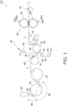
- FIG. 1 is a schematic diagram showing the overall configuration of the manufacturing apparatus 100 of the stretchable laminated sheet L.
- FIG. 2 is a cross-sectional view of the stretchable laminated sheet L in which a film F configuring the stretchable laminated sheet L is in an extended state.
- FIG. 3 is a cross-sectional view of the stretchable laminated sheet L in which the film F is in a nonextended state.
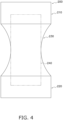
- FIG. 4 is a schematic view of a wearable article 200 that uses the stretchable laminated sheet L.
- the stretchable laminated sheet L is a stretchable sheet formed by laminating multiple sheets/films.
- the stretchable laminated sheet L includes an elastic (stretchable) film F, a first nonwoven fabric sheet S1 serving as an example of a substrate sheet, and a second nonwoven fabric sheet S2 serving as an example of a substrate sheet.
- the film F is disposed between the first nonwoven fabric sheet S1 and the second nonwoven fabric sheet S2.
- the nonwoven fabric sheets and the film F are disposed on top of each other.
- the first nonwoven fabric sheet S1 and the film F are intermittently joined together at joints J
- the second nonwoven fabric sheet S2 and the film F are intermittently joined together at joints J.
- the stretchable laminated sheet may be formed by laminating four or more sheets/films. Furthermore, the stretchable laminated sheet may have a two-layer structure comprising the film F and one of the first nonwoven fabric sheet S1 and the second nonwoven fabric sheet S2.
- nonwoven fabric sheets are examples of substrate sheets, but the substrate sheets may be sheets other than nonwoven fabric sheets.
- the first nonwoven fabric sheet S1, the film F, and the second nonwoven fabric sheet S2 are parallel to each other as in FIG. 2 .
- the film F of the stretchable laminated sheet L is being extended along the conveyance direction A
- the first nonwoven fabric sheet S1, the film F, and the second nonwoven fabric sheet S2 are parallel to each other as in FIG. 2 .
- the stretchable laminated sheet L When the stretchable laminated sheet L is released from its extended state (in a state in which no force is acting on the stretchable laminated sheet L in a direction along the conveyance direction A), the film F contracts relative to the state in FIG. 2 , so the distance between the joints J (the dotted portions) becomes shorter as in FIG. 3 . As a result, the first nonwoven fabric sheet S1 and the second nonwoven fabric sheet S2 curve, and crests and troughs are formed in the surface of the stretchable laminated sheet L (see FIG. 3 ).
- the stretchable laminated sheet L is used in wearable articles. Specifically, sheet pieces cut out along a direction orthogonal to the conveyance direction A from the stretchable laminated sheet L are used in wearable articles. It will be noted that, here, the sheet pieces cut out from the stretchable laminated sheet L will also simply be called "the stretchable laminated sheet L.”
- the wearable articles are, for example, disposable diapers or disposable medical gowns, though this is not intended to limit the types of wearable articles in which the stretchable laminated sheet L is used.
- the stretchable laminated sheet L is widely applicable to, for example, waist members of wearable articles that are worn around the waist of the wearer, wrist cuff members of wearable articles that are worn around the wrists of the wearer, and ankle cuff members of wearable articles that are worn on the ankles of the wearer, though this is not intended to limit the applications of the stretchable laminated sheet L.
- a disposable diaper serving as a wearable article 200 in which the stretchable laminated sheet L is used now will be described with reference to FIG. 4 .
- the wearable article 200 includes a front waist portion 210, a back waist portion 220, a crotch portion 230, and an absorbent article 240.
- the front waist portion 210 and the back waist portion 220 are spaced apart from each other.
- the crotch portion 230 is connected to the front waist portion 210 and the back waist portion 220.
- the front waist portion 210 and the back waist portion 220 are interconnected via the crotch portion 230.
- the absorbent article 240 is disposed so as to straddle the crotch portion 230.
- the wearable article 200 When the wearable article 200 is worn, the wearable article 200 is bent at the crotch portion 230, the front waist portion 210 is disposed on the ventral side, and the back waist portion 220 is disposed on the dorsal side. Additionally, when the wearable article 200 is worn, the front waist portion 210 and the back waist portion 220 are connected to each other by fastening members such as tapes not shown in the drawings.
- the stretchable laminated sheet L is used for the front waist portion 210 and the back waist portion 220.
- the stretchable laminated sheet L is used for the front waist portion 210 and the back waist portion 220 in a state in which the aforementioned conveyance direction A and the direction around the waist coincide.
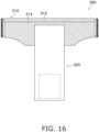
- a wearable article 300 exemplified in FIG. 16 is a disposable diaper that is substantially T-shaped when it is flatly laid out (before it is worn).
- the wearable article 300 includes a single waist member 310 and an absorbent body 320 that is attached to the waist member 310.
- the waist member 310 is a member disposed around the waist of the wearer.
- the waist member 310 includes a waistline portion 312 (the hatched portion with the positively sloping lines in FIG. 16 ) and a lower waist portion 314 (the hatched portion with the negatively sloping lines in FIG. 16 ).
- the waistline portion 312 is a portion disposed on the upper end of the waist member 310 and disposed around the waistline (covering the waistline) of the wearer (at a height position near the hip bones) when the wearable article 300 is worn.
- the lower waist portion 314 is a portion disposed below the waistline portion 312 and covers the region of the wearer's waist below the waist when the wearable article 300 is worn.
- the absorbent body 320 is attached to, in the left and right direction (width direction), the central portion of the lower waist portion 314 orthogonally to the lower waist portion 314.
- waistline portion 312 and the lower waist portion 314 may be separate members and joined together to form the waist member 310. Furthermore, the waistline portion 312 and the lower waist portion 314 may be formed integrally (by the same material).
- the absorbent body 320 is a member joined to the waist member 310 and disposed in the crotch region of the wearer when the wearable article 300 is worn.
- the absorbent body 320 has an absorbent article not shown in the drawings, and the absorbent article mainly absorbs body fluids such as urine and sweat.
- the stretchable laminated sheet L manufactured by the manufacturing method of the present disclosure is used for the waistline portion 312 and/or the lower waist portion 314 of the waist member 310 of the wearable article 300. This can realize the wearable article 300 having an improved breathability even in the portion(s) of the stretchable laminated sheet L.
- the stretchable laminated sheet L manufactured by the manufacturing method of the present disclosure openings Op1 are also formed around the joints J between the pair of nonwoven fabric sheets S1, S2 and the film F not only in the joints J. For this reason, the stretchable laminated sheet L provided in the wearable article 300 has high breathability. Furthermore, because sufficient openings are provided in the stretchable laminated sheet L, the stretchable laminated sheet L that has high stretchability is obtained, and by using this, there is also obtained the advantageous effect that the wearable article 300 that easily fits the wearer is realized.
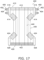
- the wearable article 400 exemplified in FIG 17 like the wearable article 200 shown in FIG. 4 , has a front waist portion 410, a back waist portion 420, a crotch portion 430, and an absorbent article 440.
- the crotch portion 430 and the absorbent article 440 are an example of the absorbent body in the claims.
- the wearable article 400 has fastening tapes 450 serving as an example of connecting members.
- the front waist portion 410 and the back waist portion 420 are both examples of a waist member disposed around the waist of the wearer.
- the front waist portion 410 and the back waist portion 420 are spaced apart from each other.
- the front waist portion 410 and the back waist portion 420 face each other.
- the front waist portion 410 and the back waist portion 420 include waistline portions 412, 422 (the hatched portions with right-up straight lines in FIG. 17 ) and lower waist portions 414, 424 (the hatched portions with right-down straight lines in FIG. 17 ).
- the waistline portion 412 is a portion disposed on the upper end of the front waist portion 410 and disposed around the waistline of the front waist of the wearer (at a height position near the hip bones) when the wearable article 400 is worn.
- the waistline portion 422 is a portion disposed on the upper end of the back waist portion 420 and disposed around the waistline of the back waist of the wearer (near the hip bones) when the wearable article is worn.
- the lower waist portions 414 are portions disposed below the waistline portion 412 and cover the region of the wearer's front waist below the waist when the wearable article is worn.
- the lower waist portions 424 are portions disposed below the waistline portion 422 and cover the region of the wearer's back waist below the waist when the wearable article is worn.
- the crotch portion 430 is attached to, in the left and right direction (width direction), central portion of the lower waist portions 414, 424 orthogonally to the lower waist portions 414, 424 and so as to straddle the lower waist portions 414, 424. That is, the crotch portion 430 is connected to the front waist portion 410 and the back waist portion 420. In other words, the front waist portion 410 and the back waist portion 420 are interconnected via the crotch portion 430.
- the crotch portion 430 is a member disposed in the crotch region of the wearer when the wearable article is worn.
- the absorbent article 440 is disposed in the central portion of the crotch portion 430 so as to lie on the crotch portion 430.
- the absorbent article 440 is a member disposed in the crotch region of the wearer together with the crotch portion 430 when the wearable article 400 is worn.
- the crotch portion 430 may be a member separate from the front waist portion 410 and the back waist portion 420 and joined to them to form the wearable article 400. Furthermore, the front waist portion 410, the back waist portion 420, and the crotch portion 430 may be formed integrally (by the same material).
- both end portions of the front waist portion 410 are provided with attachment portions 416 (the hatched portions with dots in FIG. 17 ) of the fastening tapes 450 that are an example of connecting member attachment portions.
- attachment portions 416 here mean not only the portions to which the fastening tapes 450 are attached but also the areas around the portions to which the fastening tapes 450 are attached.
- the fastening tapes 450 include hook portions 452 provided with hook-shaped projections and coupling portions 454 (the hatched portions with crosses in FIG. 17 ) having one end side attached to the attachment portions 416 and the other end side provided with the hook portions 452.
- the hook portions 452 of the fastening tapes 450 are connected (stuck) to loop portions (connected portions) 426 (the hatched portions with dots in FIG. 17 ) provided near both width direction (left and right direction) end portions of the back waist portion 420.
- the loop portions 426 are provided with numerous loop-shaped projections on which the hook-shaped projections of the hook portions 452 catch.
- the loop portions 426 may be members separate from the back waist portion 420 or may be formed by processing the back waist portion 420.
- the stretchable laminated sheet L manufactured by the manufacturing method of the present disclosure is used for the waistline portion 412 and/or the lower waist portions 414 of the front waist portion 410, and/or the waistline portion 422 and/or the lower waist portions 424 of the back waist portion 420, in the wearable article 400. Furthermore, in addition to or instead of this, the stretchable laminated sheet L is used for the attachment portions (connecting member attachment portions) 416 of the front waist portion 410 and/or the loop portions (connected portions) 426 of the back waist portion 420. Furthermore, in addition to or instead of this, the stretchable laminated sheet L is used for the coupling portions 454 of the fastening tapes 450.
- the stretchable laminated sheet L By using the stretchable laminated sheet L in this way, there can be realized the wearable article 400 that has improved breathability also in the stretchable laminated sheet L portion(s). It will be noted that in the stretchable laminated sheet L manufactured by the manufacturing method of the present disclosure, openings Op1 are formed not only around the joints J between the pair of nonwoven fabric sheets S1, S2 and the film F but also in the joints J. For this reason, the stretchable laminated sheet L provided in the wearable article 400 has high breathability. Furthermore, because sufficient openings are provided in the stretchable laminated sheet L, the stretchable laminated sheet L that has high stretchability is obtained, and by using this, there is also obtained the advantageous effect that the wearable article 400 that easily fits the wearer is realized.
- the manufacturing apparatus 100 is the following kind of apparatus.
- the manufacturing apparatus 100 manufactures the stretchable film F from a raw material.
- the manufacturing apparatus 100 conveys in an extended state the film F it has manufactured. Then, the manufacturing apparatus 100 causes the pair of nonwoven fabric sheets S1, S2 to merge with the conveyed film F and heat seals the pair of nonwoven fabric sheets S1, S2 and the film F in a state in which the film F in the extended state is disposed between the pair of nonwoven fabric sheets S1, S2 to thereby form the stretchable laminated sheet L.
- the manufacturing apparatus 100 causes the nonwoven fabric sheets S1, S2 to merge with the conveyed film F and heat seals the nonwoven fabric sheets S1, S2 and the film F in a state in which the film F in the extended state and the nonwoven fabric sheets S1, S2 are superimposed on top of each other to thereby form the stretchable laminated sheet L.
- the manufacturing apparatus 100 uses gear rolls 62, 64 to stretch (gear stretch) the stretchable laminated sheet L.
- FIG. 5 is a control block diagram of the manufacturing apparatus 100 of the stretchable laminated sheet L pertaining to the first embodiment.
- the manufacturing apparatus 100 mainly has a discharge mechanism 20, a cooling roll 30, a film stretching mechanism 38, a laminating and joining mechanism 48, a laminated sheet stretching mechanism 60, and a control device 90.
- the discharge mechanism 20 is a device that forms a film-like intermediate Fa from a raw material (a resin material).
- the intermediate Fa is eventually formed into the film F.
- the discharge mechanism 20 specifically heats and melts the resin material to a temperature higher than the temperature range in which the resin material undergoes elastic deformation and discharges in a film-like shape the molten resin material from a discharge port 24 to form the film-like intermediate Fa.
- the film-like intermediate Fa formed by the discharge mechanism 20 is conveyed to the cooling roll 30, which is disposed below the discharge mechanism 20 as in FIG. 1 .
- the resin material is, for example, a material mainly comprising a thermoplastic elastic resin, and is a material that exhibits elasticity at room temperature.
- a material mainly comprising a thermoplastic elastic resin and is a material that exhibits elasticity at room temperature.
- any of the thermoplastic elastomers prescribed in JIS K 6418:2007 (ISO 18064:2003) is used as the resin material.
- the cooling roll 30 is a device that cools and solidifies the intermediate Fa to form the elastic (stretchable) film F.
- the cooling roll 30 is driven to rotate by a drive device such as a motor not shown in the drawings. Inside the cooling roll 30 is formed a flow path, not shown in the drawings, through which flows a fluid for cooling the intermediate Fa.
- the intermediate Fa discharged from the discharge mechanism 20 is supplied to the cooling roll 30. It will be noted that the intermediate Fa discharged from the discharge port 24 of the discharge mechanism 20 is stretched in a first zone 80 (see FIG. 1 ) before reaching the cooling roll 30. In order to realize this, the cooling roll 30 rotates at a circumferential velocity greater than the feed rate of the resin material when the resin material is discharged from the discharge port 24 of the discharge mechanism 20 and stretches the film-like intermediate Fa until the thickness of the intermediate Fa reaches a predetermined value.
- the cooling roll 30 is driven to rotate by the drive device and conveys the intermediate Fa along the outer peripheral surface of the cooling roll 30.
- the cooling roll 30 cools and solidifies, in a second zone 82 in which the intermediate Fa is in contact with the outer peripheral surface of the cooling roll 30, the intermediate Fa to the temperature range in which the resin material configuring the intermediate Fa undergoes elastic deformation. Because of this, the intermediate Fa turns into the film F in the second zone 82 and is drawn off the cooling roll 30.
- the film F drawn off the cooling roll 30 is fed via a guide roll 32 to the film stretching mechanism 38.
- the guide roll 32 may, like the cooling roll 30, have the function of cooling the film F.
- the film F conveyed from the cooling roll 30 to the film stretching mechanism 38 is conveyed in a state in which it is extended by ⁇ % relative to the film F at its natural length (the length of the film F in a state in which no force is applied thereto).
- the film stretching mechanism 38 is a device that further extends the film F conveyed thereto from the cooling roll 30 in the extended state.
- the film stretching mechanism 38 mainly includes a drawing-off roll 34, a pinch roll 36, and an extension roll 40.
- the drawing-off roll 34 is driven to rotate by a drive device such as a motor not shown in the drawings.
- the extension roll 40 is driven to rotate by a drive device such as a motor not shown in the drawings.
- the drawing-off roll 34 and the pinch roll 36 are adjacently disposed.
- the drawing-off roll 34 and the pinch roll 36 pinch the film F so that the film F conveyed from the cooling roll 30 to the drawing-off roll 34 does not slide along the outer peripheral surface of the drawing-off roll 34.
- the drawing-off roll 34 rotates synchronously with the cooling roll 30.
- the film F is extended by the film stretching mechanism 38 in a third zone 84 from between the drawing-off roll 34 and the pinch roll 36 to until the film F reaches the extension roll 40.
- the extension roll 40 rotates at a circumferential velocity faster than the circumferential velocity of the drawing-off roll 34 to extend the film F by ⁇ % relative to the film F at its natural length (the length of the film F in a state in which no force is applied thereto).
- ⁇ % is a value greater than ⁇ %.
- the film F that has been extended by ⁇ % relative to the film F at its natural length is conveyed along the outer peripheral surface of the extension roll 40.
- the laminating and joining mechanism 48 forms a laminate body B in which the nonwoven fabric sheets S1, S2 and the film F that is in the extended state are superimposed. Particularly in the present embodiment, the laminating and joining mechanism 48 forms the laminate body B in which the film F in the extended state is disposed between the pair of nonwoven fabric sheets S1, S2. Moreover, the laminating and joining mechanism 48 functions as the joining unit in the claims and heat seals the nonwoven fabric sheets S1, S2 and the film F in the laminate body B to form the stretchable laminated sheet L.
- the laminating and joining mechanism 48 functions as the joining unit in the claims and heat seals the pair of nonwoven fabric sheets S1, S2 and the film F disposed between the pair of nonwoven fabric sheets S1, S2 in the laminate body B to form the stretchable laminated sheet L.
- the extension roll 40 which is a part of the configuration of the film stretching mechanism 38, also functions as a part of the laminating and joining mechanism 48. Furthermore, the laminating and joining mechanism 48 has an ultrasonic bonding device 42.
- the continuous first nonwoven fabric sheet S1 which is paid out from an original sheet roll not shown in the drawings, is supplied via a guide roll 50 to the extension roll 40 of the laminating and joining mechanism 48. Furthermore, the continuous second nonwoven fabric sheet S2, which is paid out from an original sheet roll not shown in the drawings, is supplied via guide rolls 52, 54 to the extension roll 40.
- the extended film F conveyed along the extension roll 40 is sandwiched between the first nonwoven fabric sheet S1 and the second nonwoven fabric sheet S2 that are conveyed to the extension roll 40, and the laminate body B, in which the film F in the extended state is disposed between the pair of nonwoven fabric sheets S1, S2, is formed.
- the stretchable laminated sheet L has a two-layer structure
- the continuous first nonwoven fabric sheet S1 paid out from the original sheet roll not shown in the drawings is supplied via the guide roll 50 to the extension roll 40 of the laminating and joining mechanism 48.
- the laminate body B in which the extended film F conveyed along the extension roll 40 is superimposed with the first nonwoven fabric sheet S1 conveyed to the extension roll 40, is formed.
- the laminate body B moves in accompaniment with the rotation of the extension roll 40 and passes between the extension roll 40, which functions as an anvil roll, and a horn 43 of the ultrasonic bonding device 42.
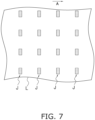
- the surface of the extension roll 40 is provided with a plurality of protruding portions 40a that are arranged along the axial direction of rotation of the extension roll 40 and arranged along the circumferential direction of the extension roll 40 (see FIG. 6 ).
- the protruding portions 40a have rectangular shapes or oblong elliptical shapes extending such that their lengthwise direction coincides with the axial direction of rotation of the extension roll 40 when the protruding portions 40a are viewed in the radial direction toward the axis of rotation of the extension roll 40.
- the shapes of the protruding portions 40a described here are merely examples and may be other shapes.
- the extension roll 40 and the horn 43 are examples of the first joining member and the second joining member in the claims.
- the horn 43 is caused to vibrate by an ultrasonic oscillator not shown in the drawings in a state in which the laminate body B is sandwiched between the horn 43 and the extension roll 40 (more specifically, between the horn 43 and the protruding portions 40a of the extension roll 40) and ultrasonically seals the nonwoven fabric sheets S1, S2 (in particular, here, the pair of nonwoven fabric sheets S1, S2) and the film F.
- Ultrasonic sealing is one form of heat sealing.
- the stretchable laminated sheet L in which the pair of nonwoven fabric sheets S1, S2 and the film F are intermittently joined together at the joints J, is formed as a result of the pair of nonwoven fabric sheets S1, S2 and the film F being ultrasonically sealed together, and is drawn off from the laminating and joining mechanism 48.
- the joints J (the dotted portions) are locally disposed.
- the stretchable laminated sheet L drawn off from the laminating and joining mechanism 48 is conveyed to the laminated sheet stretching mechanism 60 in the conveyance direction A that lies along the extension direction of the film F.
- the laminating and joining mechanism 48 serving as an example of the joining unit ultrasonically seals the nonwoven fabric sheets S1, S2 and the film F.
- the mode of the heat sealing is not limited to ultrasonic sealing.
- the laminating and joining mechanism 48 may sandwich the laminate body B between two rollers with built-in heaters and heat seal the nonwoven fabric sheets S1, S2 and the film F in a way as in FIG. 7 for example.
- the extension roll 40 which is a part of the configuration of the film stretching mechanism 38, also functions as an anvil roll in the laminating and joining mechanism 48.
- the laminating and joining mechanism 48 is not limited to this and may have an anvil roll separate from the extension roll 40 that forms the laminate body B.
- the laminated sheet stretching mechanism 60 is an example of the stretcher in the claims.
- the laminated sheet stretching mechanism 60 uses gear rolls 62, 62 to stretch (gear stretch) the stretchable laminated sheet L.
- the laminated sheet stretching mechanism 60 has a pair of gear rolls 62, 64 having recesses and projections in their peripheral surfaces. More specifically, in the gear roll 62, pluralities of tooth portions 62a and valley portions 62b are alternately provided along the circumferential direction of the gear roll 62 as in a spur gear. In the gear roll 64 also, pluralities of tooth portions 64a and valley portions 64b are alternately provided along the circumferential direction of the gear roll 64 as in a spur gear.
- gear roll 62 and the gear roll 64 are rotated by a drive mechanism such as a motor not shown in the drawings, whereby the tooth portions 62a of the gear roll 62 and the valley portions 64b of the gear roll 64, and the valley portions 62b of the gear roll 62 and the tooth portions 64a of the gear roll 64, mesh with each other.
- a drive mechanism such as a motor not shown in the drawings
- the stretchable laminated sheet L conveyed along the conveyance direction A from the laminating and joining mechanism 48 is supplied to the place where the gear roll 62 and the gear roll 64 mesh and is stretched.
- the stretchable laminated sheet L being stretched by the laminated sheet stretching mechanism 60, the film F becomes extended by ⁇ % relative to the film F at its natural length (the length of the film F in a state in which no force is applied thereto).
- the stretchable laminated sheet L that has been extended by the laminated sheet stretching mechanism 60 (the stretchable laminated sheet L in which the film F configuring the stretchable laminated sheet L has been extended by ⁇ % relative to the film F at its natural length) is conveyed by a downstream conveyance mechanism 70 while maintaining its extension ratio and is conveyed to a subsequent process (a wearable article manufacturing process neither shown in the drawings nor described).
- ⁇ % is a value greater than ⁇ %, though this is not intended to be limiting. That is, the film F (also including the film F included in the stretchable laminated sheet L) may be extended by extension ratios of ⁇ %, ⁇ (> ⁇ ) %, ⁇ (> ⁇ ) % relative to the film F at its natural length by the second zone 82, the third zone 84, and the laminated sheet stretching mechanism 60, respectively.
- the film F is extended a relatively great extent relative to the film F at its natural length by the laminated sheet stretching mechanism 60, damage to the film F is easily reduced even when the film F is extended a relatively great extent because the film F is reinforced as a result of being joined to the nonwoven fabric sheets S1, S2.
- the stretchable laminated sheet L is stretched by the laminated sheet stretching mechanism 60, openings with a sufficient area can be formed in and/or around the places where the nonwoven fabric sheets S1, S2 and the film F have been heat sealed, and the stretchable laminated sheet L that has improved breathability can be manufactured.
- openings Op are formed around the joints J so as shown in FIG. 8 .
- these openings Op are relatively small as can be seen from the photograph in FIG. 10 , and openings Op with a sufficient area for ensuring the breathability of the stretchable laminated sheet L may not be ensured.
- the film F becomes severed even for example in some of the joints J of the stretchable laminated sheet L, and as shown in FIG. 8 the film F becomes severed and openings Op1 are also formed in the joints J (the dotted portions) of the stretchable laminated sheet L in addition to the openings Op around the joints J.
- the stretchable laminated sheet L is extended in the conveyance direction A, relatively large openings become formed in the stretchable laminated sheet L as shown in FIG. 8 .
- the openings formed as a result of the laminated sheet stretching mechanism 60 performing stretching are not limited to being formed in the joints J, and there are also cases where they are formed around the joints J (formed such that the openings Op become larger). In this way, by performing gear stretching on the stretchable laminated sheet L, improved breathability in the stretchable laminated sheet L (the film F of the stretchable laminated sheet L) can be realized.
- FIGS. 8 and 9 are merely drawings for explanation and that the shapes and dimensions of the openings Op, Op1 shown in FIGS. 8 and 9 are not intended to limit the shapes of the openings that are actually formed.
- the stretchable laminated sheet L configured by the nonwoven fabrics and the thermoplastic elastic resin or the like is sandwiched by the metal gear rolls 62, 64 in the laminated sheet stretching mechanism 60, the stretchable laminated sheet L may become charged with static electricity. If the stretchable laminated sheet L becomes charged with static electricity, the static electricity may adversely affect the process in which the stretchable laminated sheet L is processed to manufacture the wearable articles. For that reason, it is preferred that the stretchable laminated sheet L be brought into contact with a grounded conductor on the downstream side of the laminated sheet stretching mechanism 60 in the conveyance direction A of the stretchable laminated sheet L.
- the control device 90 has a CPU, memories such as a ROM and a RAM, an input/output device, and various types of electrical components and electronic components not shown in the drawings.
- the control device 90 is, as shown in FIG. 5 , electrically connected to the discharge mechanism 20, the cooling roll 30, the film stretching mechanism 38, the laminating and joining mechanism 48, and the laminated sheet stretching mechanism 60.
- the control device 90 controls the discharge mechanism 20, the cooling roll 30, the film stretching mechanism 38, the laminating and joining mechanism 48, and the laminated sheet stretching mechanism 60 to operate in concert with each other.
- control device 90 may be realized by software, realized by hardware (various types of electrical circuits and electronic circuits), or realized by cooperation between software and hardware as long as it can exhibit the functions described here.
- the resin material exhibiting elasticity at room temperature is heated and melted and is discharged as the film-like intermediate Fa from the discharge port 24. Thereafter, the intermediate Fa is cooled and solidified by the cooling roll 30, and the elastic (stretchable) film F is formed.
- the discharge mechanism 20 and the cooling roll 30 function as the former in the claims, and the film F is formed from the resin material serving as a raw material. It will be noted that on the cooling roll 30 the film F is stretched to a state in which it is extended by ⁇ % relative to the film F at its natural length (the length of the film F in a state in which no force is applied thereto).
- the film F drawn off from the cooling roll 30 and conveyed in the extended state from the cooling roll 30 is further extended by the film stretching mechanism 38.
- the film stretching mechanism 38 the film F is stretched to a state in which it is extended by ⁇ (> ⁇ ) % relative to the film F at its natural length.
- the laminate body B in which the nonwoven fabric sheets S1, S2 paid out from the original sheet rolls not shown in the drawings and the film F that is in the extended state are superimposed, is formed.
- the laminate body B in which the film F in the extended state is disposed between the first nonwoven fabric sheet S1 paid out from the original sheet roll not shown in the drawings and the second nonwoven fabric sheet S2 paid out from the original sheet roll not shown in the drawings, is formed.
- the laminating and joining mechanism 48 sandwiches the laminate body B between the extension roll 40 and the horn 43 of the ultrasonic bonding device 42 and heat seals the pair of nonwoven fabric sheets S1, S2 and the film F to form them into the stretchable laminated sheet L.
- the laminated sheet stretching mechanism 60 stretches (gear stretches) the stretchable laminated sheet L, which is conveyed thereto along the conveyance direction A from the laminating and joining mechanism 48 and is conveyed between the pair of gear rolls 62, 64.
- the laminated sheet stretching mechanism 60 stretches the film F to a state in which it is extended by ⁇ % relative to the film F at its natural length.
- ⁇ % is a value greater than ⁇ %.
- the manufacturing apparatus 100 of the stretchable laminated sheet L is the apparatus 100 for manufacturing the stretchable laminated sheet L in which the nonwoven fabric sheets S1, S2 serving as examples of substrate sheets and the stretchable film F are disposed on top of each other and in which the nonwoven fabric sheets S1, S2 and the film F are joined together.
- the manufacturing apparatus 100 of the stretchable laminated sheet L includes the laminating and joining mechanism 48 serving as an example of a joining unit and the laminated sheet stretching mechanism 60 serving as an example of a stretcher.
- the laminating and joining mechanism 48 has an extension roll 40 (anvil roll) and a horn 43 serving as examples of a first joining member and a second joining member.
- the laminating and joining mechanism 48 sandwiches between the extension roll 40 and the horn 43 the laminate body B in which the nonwoven fabric sheets S1, S2 and the film F that is in an extended state are superimposed and heat seals the nonwoven fabric sheets S1, S2 and the film F to form the stretchable laminated sheet L.
- the laminated sheet stretching mechanism 60 has the pair of gear rolls 62, 64 having recesses and projections in their peripheral surfaces. The laminated sheet stretching mechanism 60 stretches the stretchable laminated sheet L which is conveyed between the pair of gear rolls 62, 64.
- the manufacturing apparatus 100 of the stretchable laminated sheet L can form openings with a sufficient area in and/or around the places where the nonwoven fabric sheets S1, S2 and the film F have been heat sealed by heat sealing the nonwoven fabric sheets S1, S2 and the film F to form the stretchable laminated sheet L and then performing stretching with the gear rolls 62, 64 having recesses and projections in their peripheral surfaces. Therefore, it can manufacture the stretchable laminated sheet L that has improved breathability.
- the manufacturing apparatus 100 of the stretchable laminated sheet L includes the discharge mechanism 20 and a cooling roll 30 that function as a former and the film stretching mechanism 38 that serves as an example of a film stretcher.
- the former forms the film F from a raw material (a resin material).
- the film stretching mechanism 38 is disposed between the former and the laminating and joining mechanism 48 in the conveyance direction A of the film F and stretches the film F.
- the extension ratio of the film F conveyed between the film stretching mechanism 38 and the laminating and joining mechanism 48 to the film F at its natural length is greater than the extension ratio of the film F conveyed between the former and the film stretching mechanism 38 to the film F at its natural length.
- the extension ratio of the film F of the stretchable laminated sheet L in the laminated sheet stretching mechanism 60 to the film F at its natural length is greater than the extension ratio of the film F conveyed between the film stretching mechanism 38 and the laminating and joining mechanism 48 to the film F at its natural length.
- the thickness of the film F can be reduced by extending the film F in stages.
- the thickness of the film F can be reduced while reducing damage to the film F.
- the stretchable laminated sheet L manufacturing method is a method of manufacturing the stretchable laminated sheet L in which the nonwoven fabric sheets S1, S2 serving as examples of substrate sheets and the stretchable film F are disposed on top of each other and in which the nonwoven fabric sheets S1, S2 and the film F are joined together.
- the stretchable laminated sheet L manufacturing method includes a sealing step and a stretching step.
- the sealing step the nonwoven fabric sheets S1, S2 and the film F that is in an extended state are heat sealed to form the stretchable laminated sheet L.
- the stretching step the stretchable laminated sheet L which is conveyed between the pair of gear rolls 62, 64 having recesses and projections in their peripheral surfaces is stretched by the pair of gear rolls 62, 64.
- This stretchable laminated sheet L manufacturing method can form openings with a sufficient area in and/or around the places where the nonwoven fabric sheets S1, S2 and the film F have been heat sealed by heat sealing the nonwoven fabric sheets S1, S2 and the film F to form the stretchable laminated sheet L and then performing stretching with the gear rolls 62, 64 having recesses and projections in their peripheral surfaces. Therefore, it can manufacture the stretchable laminated sheet L that has improved breathability.
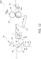
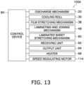
- FIG. 12 is a schematic diagram showing the configuration of the manufacturing apparatus 100A of the stretchable laminated sheet L, with illustration of the former (the discharge mechanism 20, the cooling roll 30, etc.) of the film being omitted.
- FIG. 13 is an example of a control block diagram of the manufacturing apparatus 100A of the stretchable laminated sheet L.
- the manufacturing apparatus 100A of the second embodiment differs from the manufacturing apparatus 100 of the first embodiment mainly in the following configuration "a” to configuration "c". It will be noted that the manufacturing apparatus 100A does not need to have all of configuration “a” to configuration "c".
- the manufacturing apparatus 100A may have any one of configuration "a” to configuration “c” or two of configuration "a” to configuration "c”.
- the stretchable laminated sheet L that has been formed by the laminating and joining mechanism 48 is gear stretched in the laminated sheet stretching mechanism 60, and openings are formed therein.
- the size of the opening formed in the laminated sheet stretching mechanism 60 varies depending on how much the stretchable laminated sheet L is stretched by the laminated sheet stretching mechanism 60. Additionally, how much the stretchable laminated sheet L is stretched by the laminated sheet stretching mechanism 60 also varies depending on how much tension is acting on the stretchable laminated sheet L supplied to the laminated sheet stretching mechanism 60.
- the tension acting on the stretchable laminated sheet L supplied to the laminated sheet stretching mechanism 60 be controlled to an appropriate value.
- the manufacturing apparatus 100A of the second embodiment includes the adjuster 110 that is provided between the laminating and joining mechanism 48 and the laminated sheet stretching mechanism 60 and adjusts the conveyance speed of the stretchable laminated sheet L supplied to the laminated sheet stretching mechanism 60.
- the adjuster 110 mainly has a speed adjusting roller 112 serving as an example of a second roller around which the stretchable laminated sheet L is wound and a speed regulating motor 114 that drives the speed adjusting roller 112 to rotate (see FIG. 12 and FIG. 13 ).
- the speed regulating motor 114 is electrically connected by the control device 90, and the operation of the speed regulating motor 114 (operating/stopped, rotational speed, etc.) is controlled by the control device 90.
- the speed adjusting roller 112 is a roller whose outer surface, around which the stretchable laminated sheet L is wound, has a high adhesion or coefficient of friction.
- the adhesion or coefficient of friction of the outer surface of the speed adjusting roller 112 is higher than the adhesion or coefficient of friction of the outer surfaces of guide rollers 120 serving as an example of first roller around which the stretchable laminated sheet L is wound.
- the guide rollers 120 are rollers that are disposed between the laminating and joining mechanism 48 and the adjuster 110 on the conveyance path of the stretchable laminated sheet L and guide the stretchable laminated sheet L wound around them.
- the rollers are, for example, freely rotating rollers.
- the adhesion of the outer surface of the speed adjusting roller 112 is realized by, for example, sticking an adhesive material such as rubber on the outer surface of the speed adjusting roller 112. Furthermore, the relatively high coefficient of friction of the outer surface of the speed adjusting roller 112 is realized by, for example, sticking a member with a high coefficient of friction on the outer surface of the speed adjusting roller 112 or performing a process to roughen the outer surface of the speed adjusting roller 112.
- the adjuster 110 varies the conveyance speed of the stretchable laminated sheet L in the adjuster 110 and, as a result, varies the conveyance speed of the stretchable laminated sheet L supplied to the laminated sheet stretching mechanism 60, by varying the rotational speed of the speed adjusting roller 112 having the outer surface with a relatively high adhesion or coefficient of friction.
- the adjuster 110 may use two rollers to sandwich the stretchable laminated sheet L and adjust the conveyance speed of the stretchable laminated sheet L.
- the conveyance mechanism 70 is conveying the stretchable laminated sheet L at a conveyance speed V and that the adjuster 110 is also conveying the stretchable laminated sheet L at the conveyance speed V.
- steady operation means a state in which a predetermined period has elapsed since the manufacturing apparatus 100A has started operating and the conveyance speed of the film F and the stretchable laminated sheet L has reached a constant speed. For this reason, when the manufacturing apparatus 100A starts operating or when the manufacturing apparatus 100A stops operating, the tension acting on the stretchable laminated sheet L supplied to the laminated sheet stretching mechanism 60 may become smaller such that only relatively small openings are formed in the stretchable laminated sheet L.
- the control device 90 serving as a speed controller control the operation of the adjuster 110 (more specifically, the operation of the speed regulating motor 114) to reduce the conveyance speed of the stretchable laminated sheet L in the adjuster 110 and thereby make the tension acting on the stretchable laminated sheet L supplied to the laminated sheet stretching mechanism 60 greater relative to the tension acting on the stretchable laminated sheet L conveyed from the laminating and joining mechanism 48 to the adjuster 110.
- the tension acting on the stretchable laminated sheet L supplied to the laminated sheet stretching mechanism 60 may become too large such that the openings formed in the stretchable laminated sheet L become too large or the stretchable laminated sheet L sustains damage.
- the control device 90 serving as a speed controller control the operation of the adjuster 110 (more specifically, the operation of the speed regulating motor 114) to increase the conveyance speed of the stretchable laminated sheet L in the adjuster 110 and thereby make the tension acting on the stretchable laminated sheet L supplied to the laminated sheet stretching mechanism 60 smaller relative to the tension acting on the stretchable laminated sheet L conveyed from the laminating and joining mechanism 48 to the adjuster 110.
- control device 90 serving as a speed controller control the operation of the adjuster 110 (more specifically, the operation of the speed regulating motor 114) to always keep the tension acting on the stretchable laminated sheet L supplied to the laminated sheet stretching mechanism 60 constant.
- thermoplastic film F of the stretchable laminated sheet L may harden and become difficult to stretch.
- At least one of the pair of gear rolls 62, 64 (in the present embodiment, at least the gear roll 64) is provided with a heater 66 that heats the gear rolls 62, 64 to a predetermined temperature.
- the heater 66 to heat the gear rolls 62, 64, the stretchable laminated sheet L that contacts them is also heated and becomes easier to stretch.
- the stretchable laminated sheet L be guided between the pair of gear rolls 62, 64 after contacting for a predetermined length the outer peripheral surface of the one (here, the gear roll 64) of the pair of gear rolls 62, 64 that is heated by the heater 66, so that the stretchable laminated sheet L is easily heated.
- the stretchable laminated sheet L is, for example, guided between the pair of gear rolls 62, 64 after contacting the outer peripheral surface of the gear roll 64 for 5% or more of the outer peripheral length of the gear roll 64, though this is not intended to limit the numerical value.
- the stretchable laminated sheet L conveyed from the adjuster 110 (in a case where the adjuster 110 is not provided, the stretchable laminated sheet L conveyed from the laminated sheet stretching mechanism 60) is not directly guided between the gear rolls 62, 64.
- the adjuster 110 in a case where the adjuster 110 is not provided, the stretchable laminated sheet L conveyed from the laminated sheet stretching mechanism 60
- the gear rolls 62, 64 are not directly guided between the gear rolls 62, 64.
- the stretchable laminated sheet L conveyed from the adjuster 110 (in a case where the adjuster 110 is not provided, the stretchable laminated sheet L conveyed from the laminated sheet stretching mechanism 60) is guided by a guide roller 130 so that it is wound around the outer peripheral surface of the gear roll 64, and thereafter it is guided between the gear rolls 62, 64.
- the size of the opening required in the stretchable laminated sheet L are not always constant and may vary depending on, for example, the wearable articles 200, 300, 400 in which the stretchable laminated sheet L is used.
- the settings of the gear rolls 62, 64 are, for example, the tooth depth of the gear rolls 62, 64 (the distance from the tooth roots to the tooth tips; here, the distance between the valley portions 62b and the tops of the tooth portions 62a) and the distance between the axial center of the gear roll 62 and the axial center of the gear roll 64.
- the settings of the gear rolls 62, 64 are not limited to those that have been exemplified and may also be a property of each of the gear rolls 62, 64, or properties relating to correlations between the gear roll 62 and the gear roll 64, that vary the amount of stretching by the stretchable laminated sheet L.
- the operator of the manufacturing apparatus 100A may change the settings of the gear rolls 62, 64 by trial and error, but in this case, it may take time to change the settings.
- control device 90 of the manufacturing apparatus 100A determines the settings of the gear rolls 62, 64 in the laminated sheet stretching mechanism 60 based on information relating to the size of the opening that the laminated sheet stretching mechanism 60 is to form in the stretchable laminated sheet L. For that reason, the control device 90 of the manufacturing apparatus 100A has configuration "c".
- the manufacturing apparatus 100A has a receiving unit 92 that receives information relating to the size of the opening that the laminated sheet stretching mechanism 60 is to form in the stretchable laminated sheet L.
- the receiving unit 92 is, for example, a switch or a touch panel that receives input of information by the operator of the manufacturing apparatus 100A.
- the receiving unit 92 may be a communication device that receives information sent via a network such as the internet from a terminal (e.g., a computer serving as a management device that manages the manufacturing apparatus 100A or a portable terminal carried by the operator) operated by the operator of the manufacturing apparatus 100A.
- the information relating to the size of the opening that the laminated sheet stretching mechanism 60 is to form in the stretchable laminated sheet L is, for example, a numerical value representing the ratio of the desired opening size to the sealing area in which the laminating and joining mechanism 48 seals the nonwoven fabric sheets S1, S2 and the film F.
- the information relating to the size of the opening that the laminated sheet stretching mechanism 60 is to form in the stretchable laminated sheet L may, for example, also be the numerical value itself of the desired opening size.
- the information relating to the size of the opening that the laminated sheet stretching mechanism 60 is to form in the stretchable laminated sheet L may also, for example, be relative indicators indicating the desired opening size, such as "large”, “medium”, and "small".
- control device 90 of the manufacturing apparatus 100A functions as a determining unit in the claims and determines the settings of the gear rolls 62, 64 in the laminated sheet stretching mechanism 60 based on the information, which has been received by the receiving unit 92, relating to the size of the opening that the laminated sheet stretching mechanism 60 is to form in the stretchable laminated sheet L.
- the memories of the control device 90 store correlation information in which the size of the opening that the laminated sheet stretching mechanism 60 is to form in the stretchable laminated sheet L and the settings of the gear rolls 62, 64 are correlated with each other.
- the correlation information is information based on test results obtained by using a test device for testing the manufacturing apparatus 100A, gear stretching the stretchable laminated sheet L while changing the settings of the gear rolls 62, 64, and measuring the openings formed by the gear stretching.
- the correlation information is information relating to correlations between the settings of the gear rolls 62, 64 and the openings formed by the gear stretching, which is calculated theoretically or obtained by computer simulation.
- the control device 90 references the correlation information to determine the settings of the gear rolls 62, 64 corresponding to the information, received by the receiving unit 92, relating to the size of the opening that the laminated sheet stretching mechanism 60 is to form in the stretchable laminated sheet L.
- the manufacturing apparatus 100A has, for example, a display serving as an output unit 94, and the control device 90 displays on the display serving as the output unit 94 the settings of the gear rolls 62, 64 on which it has determined.
- the manufacturing apparatus 100A may, for example, have a communication device serving as the output unit 94, and the control device 90 may send the settings of the gear rolls 62, 64 on which it has determined to a terminal (e.g., a computer serving as a management device that manages the manufacturing apparatus 100A or a portable terminal carried by the operator) operated by the operator of the manufacturing apparatus 100A.
- a terminal e.g., a computer serving as a management device that manages the manufacturing apparatus 100A or a portable terminal carried by the operator
- the operator of the manufacturing apparatus 100A can replace the gear rolls 62, 64 used in the laminated sheet stretching mechanism 60 or regulate the distance between the axial center of the gear roll 62 and the axial center of the gear roll 64 based on the settings of the gear rolls 62, 64 that the control device 90 outputs from the output unit 94.
- the manufacturing apparatus 100A of the second embodiment has the following characteristics in addition to the characteristics described in "(4) Characteristics" of the manufacturing apparatus 100 of the first embodiment.
- the manufacturing apparatus 100A of the stretchable laminated sheet L includes the adjuster 110 and the control device 90 serving as a speed controller.
- the adjuster 110 is disposed between the laminating and joining mechanism 48 and the laminated sheet stretching mechanism 60 on the conveyance path of the stretchable laminated sheet L and adjusts the conveyance speed of the stretchable laminated sheet L supplied to the laminated sheet stretching mechanism 60.
- the control device 90 controls the operation of the adjuster 110.
- the conveyance speed of the stretchable laminated sheet L supplied to the laminated sheet stretching mechanism 60 is controlled, and as a result the tension acting on the stretchable laminated sheet L supplied to the laminated sheet stretching mechanism 60 is controlled. For that reason, the occurrence of problems such as excessive tension acting on the stretchable laminated sheet L in the laminated sheet stretching mechanism 60 and damaging the stretchable laminated sheet L or the size of the opening formed in the stretchable laminated sheet L in the laminated sheet stretching mechanism 60 being different from the desired size can be reduced.
- control device 90 controls the operation of the adjuster 110 to make the tension acting on the stretchable laminated sheet L supplied to the laminated sheet stretching mechanism 60 smaller relative to the tension acting on the stretchable laminated sheet L conveyed from the laminating and joining mechanism 48 to the adjuster 110.
- the occurrence of the problem of excessive tension acting on the stretchable laminated sheet L in the laminated sheet stretching mechanism 60 and damaging the stretchable laminated sheet L during steady operation can be reduced.
- control device 90 controls the operation of the adjuster 110 to make the tension acting on the stretchable laminated sheet L supplied to the laminated sheet stretching mechanism 60 greater relative to the tension acting on the stretchable laminated sheet L conveyed from the laminating and joining mechanism 48 to the adjuster 110.
- the control device 90 does not control the operation of the adjuster 110.
- the tension acting on the stretchable laminated sheet L supplied to the laminated sheet stretching mechanism 60 is smaller compared with that of during steady operation, and there is a possibility that the size of the opening formed in the stretchable laminated sheet L by the laminated sheet stretching mechanism 60 will be smaller compared with that of during steady operation. If the openings are too small, the stretchable laminated sheet L will not have the desired breathability, so the parts of the stretchable laminated sheet L where the openings are too small may not be usable for wearable articles (will be wasted).
- the manufacturing apparatus 100A of the stretchable laminated sheet L controls the operation of the adjuster 110 to increase the tension acting on the stretchable laminated sheet L supplied to the laminated sheet stretching mechanism 60, so even when the manufacturing apparatus 100A of the stretchable laminated sheet L starts operating or stops operating, openings with an appropriate size can be formed in the stretchable laminated sheet L in the laminated sheet stretching mechanism 60.
- control device 90 controls the operation of the adjuster 110 to keep the tension acting on the stretchable laminated sheet L supplied to the laminated sheet stretching mechanism 60 constant.
- the tension acting on the stretchable laminated sheet L supplied to the laminated sheet stretching mechanism 60 is constant, so openings with generally the same size tend to always be formed in the stretchable laminated sheet L.
- the manufacturing apparatus 100A of the stretchable laminated sheet L includes the guide rollers 120 serving as an example of a first roller.
- the guide rollers 120 are disposed between the laminating and joining mechanism 48 and the adjuster 110 on the conveyance path and guide the stretchable laminated sheet L that is wound around the guide rollers 120.
- the adjuster 120 includes the speed adjusting roller 112 serving as an example of a second roller around which the stretchable laminated sheet L is wound.
- the outer surface of the speed adjusting roller 112 has a higher adhesion or coefficient of friction than the outer surfaces of the guide rollers 120.
- the stretchable laminated sheet L can be gripped by the outer surface of the speed adjusting roller 112 in the adjuster 110, and the conveyance speed of the stretchable laminated sheet L supplied to the laminated sheet stretching mechanism 60 can be adjusted using a single roller.
- the adjuster 110 may also use two rollers to sandwich the stretchable laminated sheet L and adjust the conveyance speed of the stretchable laminated sheet L.
- the manufacturing apparatus 100A of the stretchable laminated sheet L includes the heater 66 that heats at least one of the pair of gear rolls 62, 64.
- the manufacturing apparatus 100A of the stretchable laminated sheet L includes the heater 66 that heats at least the gear roll 64.
- the stretchable laminated sheet L can be heated and then stretched, so the stretchable laminated sheet L is easily stretched in the laminated sheet stretching mechanism 60.
- the stretchable laminated sheet L is guided between the pair of gear rolls 62, 64 after contacting for a predetermined length the outer peripheral surface of the one of the pair of gear rolls 62, 64 that is heated by the heater 66.
- the stretchable laminated sheet L is guided between the pair of gear rolls 62, 64 after contacting for a predetermined length the outer peripheral surface of the one of the gear roll 64 that is heated by the heater 66.
- the stretchable laminated sheet L is easily sufficiently heated, and the stretchable laminated sheet L is easily sufficiently stretched in the laminated sheet stretching mechanism 60.
- the manufacturing apparatus 100A of the stretchable laminated sheet L includes the receiving unit 92 and the control device 90.
- the receiving unit 92 receives information relating to the size of the opening that the laminated sheet stretching mechanism 60 is to form in the stretchable laminated sheet L.
- the control device 90 determines the settings of the gear rolls 62, 64 in the laminated sheet stretching mechanism 60 based on the information relating to the size of the opening that the laminated sheet stretching mechanism 60 is to form in the stretchable laminated sheet L.
- the settings of the gear rolls 62, 64 are determined in accordance with the size of the opening to be provided in the stretchable laminated sheet L, so in the laminated sheet stretching mechanism 60, openings with the desired size are easily formed in the stretchable laminated sheet L.
- the manufacturing apparatus 100A may have the following configuration instead of the configuration "c".
- the control device 90 controls the operation of the adjuster 110 to change the tension acting on the stretchable laminated sheet L supplied to the laminated sheet stretching mechanism 60.
- control device 90 may determine the control pattern of the adjuster 110 rather than deciding on the settings of the gear rolls 62, 64 in accordance with the size of the opening required in the stretchable laminated sheet L.
- the manufacturing apparatus 100A of example modification 1 has a receiving unit 92 that receives information relating to the size of the opening that the laminated sheet stretching mechanism 60 is to form in the stretchable laminated sheet L. Since the receiving unit 92 and the information relating to the size of the opening that the laminated sheet stretching mechanism 60 is to form in the stretchable laminated sheet L have already been described in the second embodiment, description thereof will be omitted here.
- the control device 90 of the manufacturing apparatus 100A determines the control pattern of the adjuster 110 based on the information, received by the receiving unit 92, relating to the size of the opening that the laminated sheet stretching mechanism 60 is to form in the stretchable laminated sheet L.
- the memories of the control device 90 stores correlation information in which the size of the opening that the laminated sheet stretching mechanism 60 is to form in the stretchable laminated sheet L and control patterns of the adjuster 110 (a method of how to control the rotational speed of the speed regulating motor 114 when the manufacturing apparatus 100A starts operating, when the manufacturing apparatus 100A stops operating, and during steady operation) are correlated with each other.
- the correlation information here is information based on test results obtained by using a test device for testing the manufacturing apparatus 100A, gear stretching the stretchable laminated sheet L while changing the control pattern of the adjuster 110, and measuring the openings formed by the gear stretching.
- the correlation information is information relating to correlations between the control pattern of the adjuster 110 and the openings formed by the gear stretching, which is calculated theoretically or obtained by computer simulation.
- the control device 90 references the correlation information to determine the control pattern of the adjuster 110 corresponding to the information, received by the receiving unit 92, relating to the size of the opening that the laminated sheet stretching mechanism 60 is to form in the stretchable laminated sheet L.
- the manufacturing apparatus 100A may, for example, output the control pattern of the adjuster 110 on which it has decided from the output unit 94 (description regarding the output unit 94 is omitted). Additionally, the operator of the manufacturing apparatus 100A may input the control pattern of the adjuster 110 to the control device 90. Furthermore, the control device 90 may, during the operation of the manufacturing apparatus 100A, control the operation of the adjuster 110 using the settings of the control pattern of the adjuster 110 on which it has determined.
- the tension acting on the stretchable laminated sheet L supplied to the laminated sheet stretching mechanism 60 is changed in accordance with the information relating to the size of the opening that the laminated sheet stretching mechanism 60 is to form in the stretchable laminated sheet L.
- the manufacturing apparatus 100A is not limited to this and may automatically change the settings of the gear rolls 62, 64 in accordance with the size of the opening required in the stretchable laminated sheet L.
- FIG. 14 is a schematic view showing the configuration of the manufacturing apparatus 100A of the stretchable laminated sheet L of example modification 2, with illustration of the former of the film F being omitted.
- FIG. 15 is a control block diagram of the manufacturing apparatus 100A of the stretchable laminated sheet L of example modification 2.
- the manufacturing apparatus 100A of example modification 2 has a drive mechanism 68 that moves at least one of the axial center of the gear roll 62 and the axial center of the gear roll 64 toward and away from that of the other gear roll (see FIG. 14 and FIG. 15 ). As shown in FIG. 15 , the manufacturing apparatus 100A of example modification 2 does not have the output unit 94. However, the manufacturing apparatus 100A is not limited to this and may have the output unit 94.
- the manufacturing apparatus 100A of example modification 2 determines, by the same method as that of the manufacturing apparatus 100A of the second embodiment, on the setting of the gear rolls 62, 64 in the laminated sheet stretching mechanism 60 (here, the distance between the axial center of the gear roll 62 and the axial center of the gear roll 64) based on the information, received by the receiving unit 92, relating to the size of the opening that the laminated sheet stretching mechanism 60 is to form in the stretchable laminated sheet L.
- control device 90 instead of outputting from the output unit 94 the settings of the gear rolls 62, 64 on which it has determined, controls the operation of the drive mechanism 68 to adjust the distance between the axial center of the gear roll 62 and the axial center of the gear roll 64 to the distance between the axial center of the gear roll 62 and the axial center of the gear roll 64 on which it has determined.
- a stretchable laminated sheet manufacturing apparatus is an apparatus for manufacturing a stretchable laminated sheet in which a substrate sheet and a stretchable film are disposed on top of each other and in which the substrate sheet and the film are joined together.
- the stretchable laminated sheet manufacturing apparatus includes a joining unit and a stretcher.
- the joining unit has a first joining member and a second joining member.
- the joining unit is configured to sandwich between the first joining member and the second joining member a laminate body in which the substrate sheet and the film that is in an extended state are superimposed and heat seals the substrate sheet and the film to form the stretchable laminated sheet.
- the stretcher has a pair of gear rolls having recesses and projections in their peripheral surfaces. The stretcher is configured to stretch the stretchable laminated sheet which is conveyed between the pair of gear rolls.
- the stretchable laminated sheet manufacturing apparatus of the first aspect can form openings with a sufficient area in and/or around the places where the substrate sheet and the film have been heat sealed by heat sealing the substrate sheet and the film to form the stretchable laminated sheet and then performing stretching with the gear rolls having recesses and projections in their peripheral surfaces. Therefore, it can manufacture the stretchable laminated sheet that has improved breathability.
- a stretchable laminated sheet manufacturing apparatus of a second aspect is the stretchable laminated sheet manufacturing apparatus of the first aspect, including a former and a film stretcher.
- the former is configured to form the film from a raw material.
- the film stretcher is disposed between the former and the joining unit in a conveyance direction of the film and stretches the film.
- An extension ratio of the film conveyed between the film stretcher and the joining unit to the film at its natural length is greater than an extension ratio of the film conveyed between the former and the film stretcher to the film at its natural length.
- An extension ratio of the film of the stretchable laminated sheet in the stretcher to the film at its natural length is greater than the extension ratio of the film conveyed between the film stretcher and the joining unit to the film at its natural length.
- the thickness of the film can be reduced by extending the film in stages.
- this stretchable laminated sheet manufacturing apparatus by using the film to form the stretchable laminated sheet and thereafter further stretching the film, the thickness of the film can be reduced while reducing damage to the film.
- a stretchable laminated sheet manufacturing apparatus of a third aspect is the stretchable laminated sheet manufacturing apparatus of the first aspect or the second aspect, further including an adjuster and a speed controller.
- the adjuster is disposed between the joining unit and the stretcher on a conveyance path of the stretchable laminated sheet and is configured to adjust the conveyance speed of the stretchable laminated sheet supplied to the stretcher.
- the speed controller is configured to control the operation of the adjuster.
- the conveyance speed of the stretchable laminated sheet supplied to the stretcher is controlled, and as a result the tension acting on the stretchable laminated sheet supplied to the stretcher is controlled. For that reason, the occurrence of problems such as excessive tension acting on the stretchable laminated sheet in the stretcher and damaging the stretchable laminated sheet or the size of the opening formed in the stretchable laminated sheet in the stretcher being different from the desired size can be reduced.
- a stretchable laminated sheet manufacturing apparatus of a fourth aspect is the stretchable laminated sheet manufacturing apparatus of the third aspect, wherein the speed controller is configured to control, during steady operation, the operation of the adjuster to make a tension acting on the stretchable laminated sheet supplied to the stretcher smaller relative to a tension acting on the stretchable laminated sheet conveyed from the joining unit to the adjuster.
- the occurrence of the problem of excessive tension acting on the stretchable laminated sheet in the stretcher and damaging the stretchable laminated sheet during steady operation can be reduced.
- a stretchable laminated sheet manufacturing apparatus of a fifth aspect is the stretchable laminated sheet manufacturing apparatus of the third aspect or the fourth aspect, wherein when the manufacturing apparatus starts operating or stops operating, the speed controller is configured to control the operation of the adjuster to make a tension acting on the stretchable laminated sheet supplied to the stretcher greater relative to a tension acting on the stretchable laminated sheet conveyed from the joining unit to the adjuster.
- the speed controller does not control the operation of the adjuster.
- the tension acting on the stretchable laminated sheet supplied to the stretcher becomes smaller compared with that of during steady operation, and there is a possibility that the size of the opening formed in the stretchable laminated sheet by the stretcher will be smaller compared with that of during steady operation. If the openings are too small, the stretchable laminated sheet will not have the desired breathability, so the parts of the stretchable laminated sheet where the openings are too small may not be usable for wearable articles (will be wasted).
- the stretchable laminated sheet manufacturing apparatus of the fifth aspect controls the operation of the adjuster to increase the tension acting on the stretchable laminated sheet supplied to the stretcher, so even when the stretchable laminated sheet manufacturing apparatus starts operating or stops operating, openings with an appropriate size can be formed in the stretchable laminated sheet in the stretcher.
- a stretchable laminated sheet manufacturing apparatus of a sixth aspect is the stretchable laminated sheet manufacturing apparatus of the third aspect, wherein the speed controller is configured to control the operation of the adjuster to keep a tension acting on the stretchable laminated sheet supplied to the stretcher constant.
- the tension acting on the stretchable laminated sheet supplied to the stretcher is constant, so openings with generally the same size tend to always be formed in the stretchable laminated sheet.
- a stretchable laminated sheet manufacturing apparatus of a seventh aspect is the stretchable laminated sheet manufacturing apparatus of any of the third aspect to the sixth aspect, further includes a first roller.
- the first roller is disposed between the joining unit and the adjuster on the conveyance path and is configured to guide the stretchable laminated sheet that is wound around it.
- the adjuster includes a second roller around which the stretchable laminated sheet is wound. An outer surface of the second roller has a higher adhesion or coefficient of friction than an outer surface of the first roller.
- the stretchable laminated sheet can be gripped by the outer surface of the second roller in the adjuster, and the conveyance speed of the stretchable laminated sheet supplied to the stretcher can be adjusted using a single roller.
- a stretchable laminated sheet manufacturing apparatus of an eighth aspect is the stretchable laminated sheet manufacturing apparatus of any of the first aspect to the seventh aspect, further including a heater configured to heat at least one of the pair of gear rolls.
- the stretchable laminated sheet can be heated and then stretched, so the stretchable laminated sheet is easily stretched in the stretcher.
- a stretchable laminated sheet manufacturing apparatus of a ninth aspect is the stretchable laminated sheet manufacturing apparatus of the eighth aspect, wherein the stretchable laminated sheet is configured to be guided between the pair of gear rolls after contacting for a predetermined length an outer peripheral surface of the one of the pair of gear rolls that is heated by the heater.
- the stretchable laminated sheet is easily sufficiently heated, and the stretchable laminated sheet is easily sufficiently stretched in the stretcher.
- a stretchable laminated sheet manufacturing apparatus of a tenth aspect is the stretchable laminated sheet manufacturing apparatus of any of the first aspect to the ninth aspect, further including a receiving unit and a determining unit.
- the receiving unit is configured to receive information relating to a size of an opening that the stretcher is to form in the stretchable laminated sheet.
- the determining unit is configured to determine a setting of the gear rolls in the stretcher based on the information relating to the size of openings that the stretcher is to form in the stretchable laminated sheet.
- the settings of the gear rolls are decided on in accordance with the size of the opening to be provided in the stretchable laminated sheet, so in the stretcher, openings with the desired size are easily formed in the stretchable laminated sheet.
- a stretchable laminated sheet manufacturing apparatus of an eleventh aspect is the stretchable laminated sheet manufacturing apparatus of any of the first aspect to the ninth aspect, further comprising a receiving unit.
- the receiving unit is configured to receive information relating to a size of an opening that the stretcher is to form in the stretchable laminated sheet.
- the tension acting on the stretchable laminated sheet supplied to the stretcher is changed in accordance with the information relating to the size of the opening that the stretcher is to form in the stretchable laminated sheet.
- the tension in the stretchable laminated sheet supplied to the stretcher is changed in accordance with the size of the opening to be provided in the stretchable laminated sheet, so in the stretcher, openings with the desired size are easily formed in the stretchable laminated sheet.
- a stretchable laminated sheet manufacturing method of a twelfth aspect is a method of manufacturing a stretchable laminated sheet in which a substrate sheet and a stretchable film are disposed on top of each other and in which a pair of the substrate sheets and the film are joined together.
- the stretchable laminated sheet manufacturing method includes a sealing step and a stretching step.
- the sealing step the substrate sheet and the film that is in an extended state are heat sealed to form the stretchable laminated sheet.
- the stretching step the stretchable laminated sheet which is conveyed between a pair of gear rolls having recesses and projections in their peripheral surfaces is stretched by the pair of gear rolls.
- the stretchable laminated sheet manufacturing method of the twelfth aspect can form openings with a sufficient area in and/or around the places where the substrate sheet and the film have been heat sealed (see FIG. 9 and FIG. 11 ) by heat sealing the substrate sheet and the film to form the stretchable laminated sheet and then performing stretching with the gear rolls having recesses and projections in their peripheral surfaces. Therefore, it is possible to manufacture the stretchable laminated sheet that has improved breathability.
- a wearable article of a thirteenth aspect comprises a waist member and an absorbent body.
- the waist member is disposed around a waist of a wearer when the wearable article is worn.
- the absorbent body is joined to the waist member and disposed in a crotch region of the wearer.
- the waist member includes a waistline portion that is disposed on an upper end of the waist member and disposed around a waistline of the wearer when the wearable article is worn.
- a stretchable laminated sheet manufactured by the manufacturing method of the twelfth aspect is used for the waistline portion.
- a wearable article of a fourteenth aspect includes a waist member and an absorbent body.
- the waist member is disposed around a waist of a wearer when the wearable article is worn.
- the absorbent body is joined to the waist member and disposed in a crotch region of the wearer when the wearable article is worn.
- the waist member includes a waistline portion and a lower waist portion.
- the waistline portion is configured to be disposed on an upper end of the waist member and is configured to be disposed around a waistline of the wearer when the wearable article is worn.
- the lower waist portion is configured to be disposed below the waistline stretchable portion when the wearable article is worn.
- a stretchable laminated sheet manufactured by the manufacturing method of the twelfth aspect is used for the lower waist portion.
- a wearable article of a fifteenth aspect includes a waist member, an absorbent body, and a connecting member.
- the waist member is configured to be disposed around a waist of a wearer when the wearable article is worn.
- the absorbent body is joined to the waist member and is configured to be disposed in a crotch region of the wearer when the wearable article is worn.
- the connecting member is attached to a connecting member attachment portion provided on at least one of left and right end portions of the waist member.
- the connecting member is configured to be connected to a connected portion of the waist member when the wearable article is worn.
- a stretchable laminated sheet manufactured by the manufacturing method of the twelfth aspect is used for the connecting member attachment portion or the connected portion.
- a wearable article of a sixteenth aspect includes a waist member, an absorbent body, and a connecting member.
- the waist member is disposed around a waist of a wearer when the wearable article is worn.
- the absorbent body is joined to the waist member and is configured to be disposed in the crotch region of a wearer when the wearable article is worn.
- the connecting members are attached to connecting member attachment portions provided on at least one of left and right end portions of the waist member.
- the connecting member is configured to be connected to a connected portion of the waist member when the wearable article is worn.
- a stretchable laminated sheet manufactured by the manufacturing method of the twelfth aspect is used for the connecting member.
- wearable articles of the thirteenth aspect to the sixteenth aspect wearable articles that have improved breathability are realized because of the stretchable laminated sheet.
- a wearable article of a seventeenth aspect includes a waist member, an absorbent body, and a connecting member.
- the waist member is configured to be disposed around a waist of a wearer when the wearable article is worn.
- the absorbent body is joined to the waist member and is configured to be disposed in the crotch region of a wearer when the wearable article is worn.
- the connecting member is attached to a connecting member attachment portion provided on at least one of left and right end portions of the waist member.
- the connecting member is configured to be connected to a connected portion of the waist member when the wearable article is worn.
- a stretchable laminated sheet in which a substrate sheet and a stretchable film are joined together in a superimposed state and in which openings are formed in joints between the substrate sheet and the film, is used for at least one of the waist member and the connecting member.
- the stretchable laminated sheet in which openings are also formed in the joints between the substrate sheet and the film, is used, so the wearable article that has improved breathability is realized.
Landscapes
- Engineering & Computer Science (AREA)
- Mechanical Engineering (AREA)
- Health & Medical Sciences (AREA)
- Textile Engineering (AREA)
- Life Sciences & Earth Sciences (AREA)
- Public Health (AREA)
- Heart & Thoracic Surgery (AREA)
- Vascular Medicine (AREA)
- Epidemiology (AREA)
- Animal Behavior & Ethology (AREA)
- General Health & Medical Sciences (AREA)
- Biomedical Technology (AREA)
- Veterinary Medicine (AREA)
- Manufacturing & Machinery (AREA)
- Laminated Bodies (AREA)
- Lining Or Joining Of Plastics Or The Like (AREA)
- Nonwoven Fabrics (AREA)
- Absorbent Articles And Supports Therefor (AREA)
Abstract
Description
- The present invention relates to an apparatus for and a method of manufacturing a stretchable laminated sheet used in a wearable article and to a wearable article using the stretchable laminated sheet.
- Conventionally, apparatus for and methods of manufacturing a stretchable laminated sheet, in which nonwoven fabric sheets and a stretchable film are superimposed and which is used in wearable articles, have been known (e.g., see Patent Document 1 (International Publication No. 2019/150801)). The stretchable laminated sheet is, for example, used for waist portions of the wearable articles and is worn on the waist of the wearer.
- Of the sheets used to manufacture the stretchable laminated sheet, the nonwoven fabric sheets are breathable, but the stretchable film is not. For that reason, when the stretchable laminated sheet is used in a wearable article, the problem may arise that the wearer feels stuffiness when wearing the wearable article.
- However, in a case where the nonwoven fabric sheets and the film are heat fused in the process of manufacturing the stretchable laminated sheet, the film breaks around the heat fused areas. For that reason, when the wearer wears a wearable article that uses the stretchable laminated sheet, air can pass through the broken portions of the film, so the problem of the wearer feeling stuffiness when wearing the wearable article can be suppressed to some extent.
- Patent Document 1: International Publication No.
2019/150801 - However, such breaks in the film around the heat fused areas may not be able to ensure openings with sufficient areas and sufficiently suppress the problem of the wearer feeling stuffiness when wearing the wearable article.
- It is an object of the present invention to provide an apparatus for and a method of manufacturing a stretchable laminated sheet that has improved breathability and a wearable article using the stretchable laminated sheet that has improved breathability.
- The stretchable laminated sheet manufacturing apparatus of the present invention is an apparatus for manufacturing a stretchable laminated sheet in which a substrate sheet and a stretchable film are disposed on top of each other and in which the substrate sheet and the film are joined together. The stretchable laminated sheet manufacturing apparatus comprises a joining unit and a stretcher. The joining unit has a first joining member and a second joining member. The joining unit is configured to sandwich between the first joining member and the second joining member a laminate body in which the substrate sheet and the film that is in an extended state are superimposed and heat seal the substrate sheet and the film to form the stretchable laminated sheet. The stretcher has a pair of gear rolls having recesses and projections in their peripheral surfaces. The stretcher is configured to stretch the stretchable laminated sheet which is conveyed between the pair of gear rolls.
- The stretchable laminated sheet manufacturing method of the present invention is a method of manufacturing a stretchable laminated sheet in which a substrate sheet and a stretchable film are disposed on top of each other and in which the substrate sheet and the film are joined together. The stretchable laminated sheet manufacturing method comprising a sealing step and a stretching step. In the sealing step, the substrate sheet and the film that is in an extended state are heat sealed to form the stretchable laminated sheet. In the stretching step, the stretchable laminated sheet which is conveyed between a pair of gear rolls having recesses and projections in their peripheral surfaces is stretched by the pair of gear rolls.
- The apparatus for and method of manufacturing a stretchable laminated sheet of the present invention can, by heat sealing the substrate sheet and the film to form the stretchable laminated sheet and then performing stretching with the gear rolls having recesses and projections in their peripheral surfaces, form an opening with a sufficient area in and/or around the place where the substrate sheet and the film have been heat sealed and manufacture the stretchable laminated sheet that has improved breathability.
-
-
FIG. 1 is a schematic diagram showing the overall configuration of a stretchable laminated sheet manufacturing apparatus of a first embodiment. -
FIG. 2 is a schematic cross-sectional view of the stretchable laminated sheet in which a film is in an extended state. -
FIG. 3 is a schematic cross-sectional view of the stretchable laminated sheet in which the film is in a nonextended state. -
FIG. 4 is a schematic view of a wearable article that uses the stretchable laminated sheet. -
FIG. 5 is a control block diagram of the stretchable laminated sheet manufacturing apparatus ofFIG. 1 . -
FIG. 6 is a schematic enlarged view of an extension roll and a horn of the stretchable laminated sheet manufacturing apparatus ofFIG. 1 . -
FIG. 7 is a drawing showing an example of the arrangement of connected portions formed in the stretchable laminated sheet. -
FIG. 8 is a schematic partially enlarged plan of the stretchable laminated sheet before gear stretching and a schematic cross-sectional view taken from the perspective of X1-X1 in the schematic partially enlarged plan view. -
FIG. 9 is a schematic partially enlarged plan of the stretchable laminated sheet after the gear stretching and a schematic cross-sectional view taken from the perspective of X2-X2 in the schematic partially enlarged plan view. -
FIG. 10 is a photograph of the stretchable laminated sheet before the gear stretching. -
FIG. 11 is a photograph of the stretchable laminated sheet after the gear stretching. -
FIG. 12 is a schematic diagram showing the configuration of a stretchable laminated sheet manufacturing apparatus of a second embodiment, with illustration of a film former being omitted. -
FIG. 13 is a control block diagram of the stretchable laminated sheet manufacturing apparatus ofFIG. 12 . -
FIG. 14 is a schematic diagram showing the configuration of a stretchable laminated sheet manufacturing apparatus ofexample modification 2, with illustration of the film former being omitted. -
FIG. 15 is a control block diagram of the stretchable laminated sheet manufacturing apparatus ofFIG. 14 . -
FIG. 16 is a drawing showing an example of places where the stretchable laminated sheet is used in a wearable article pertaining to one example. -
FIG. 17 is a drawing showing an example of places where the stretchable laminated sheet is used in a wearable article pertaining to another example. - Apparatus for and methods of manufacturing a stretchable laminated sheet of embodiments of the present invention will be described below with reference to the drawings.
- A
manufacturing apparatus 100 of stretchable laminated sheet L pertaining to a first embodiment will now be described with reference toFIG. 1 to FIG. 4 .FIG. 1 is a schematic diagram showing the overall configuration of themanufacturing apparatus 100 of the stretchable laminated sheet L.FIG. 2 is a cross-sectional view of the stretchable laminated sheet L in which a film F configuring the stretchable laminated sheet L is in an extended state.FIG. 3 is a cross-sectional view of the stretchable laminated sheet L in which the film F is in a nonextended state.FIG. 4 is a schematic view of awearable article 200 that uses the stretchable laminated sheet L. - First, the stretchable laminated sheet L manufactured by the
manufacturing apparatus 100 will be described. - The stretchable laminated sheet L is a stretchable sheet formed by laminating multiple sheets/films. The stretchable laminated sheet L, as shown in
FIG. 2 and FIG. 3 , includes an elastic (stretchable) film F, a first nonwoven fabric sheet S1 serving as an example of a substrate sheet, and a second nonwoven fabric sheet S2 serving as an example of a substrate sheet. In the stretchable laminated sheet L, the film F is disposed between the first nonwoven fabric sheet S1 and the second nonwoven fabric sheet S2. In other words, in the stretchable laminated sheet L, the nonwoven fabric sheets and the film F are disposed on top of each other. In the stretchable laminated sheet L, the first nonwoven fabric sheet S1 and the film F are intermittently joined together at joints J, and the second nonwoven fabric sheet S2 and the film F are intermittently joined together at joints J. - It will be noted that although a three-layer structure comprising the first nonwoven fabric sheet S1, the second nonwoven fabric sheet S2, and the film F is described as an example here, the stretchable laminated sheet may be formed by laminating four or more sheets/films. Furthermore, the stretchable laminated sheet may have a two-layer structure comprising the film F and one of the first nonwoven fabric sheet S1 and the second nonwoven fabric sheet S2.
- Moreover, the nonwoven fabric sheets are examples of substrate sheets, but the substrate sheets may be sheets other than nonwoven fabric sheets.
- When the stretchable laminated sheet L is being sufficiently extended along a conveyance direction A of the stretchable laminated sheet L in the
manufacturing apparatus 100 described later, the first nonwoven fabric sheet S1, the film F, and the second nonwoven fabric sheet S2 are parallel to each other as inFIG. 2 . In other words, when the film F of the stretchable laminated sheet L is being extended along the conveyance direction A, the first nonwoven fabric sheet S1, the film F, and the second nonwoven fabric sheet S2 are parallel to each other as inFIG. 2 . - When the stretchable laminated sheet L is released from its extended state (in a state in which no force is acting on the stretchable laminated sheet L in a direction along the conveyance direction A), the film F contracts relative to the state in
FIG. 2 , so the distance between the joints J (the dotted portions) becomes shorter as inFIG. 3 . As a result, the first nonwoven fabric sheet S1 and the second nonwoven fabric sheet S2 curve, and crests and troughs are formed in the surface of the stretchable laminated sheet L (seeFIG. 3 ). - The stretchable laminated sheet L is used in wearable articles. Specifically, sheet pieces cut out along a direction orthogonal to the conveyance direction A from the stretchable laminated sheet L are used in wearable articles. It will be noted that, here, the sheet pieces cut out from the stretchable laminated sheet L will also simply be called "the stretchable laminated sheet L." The wearable articles are, for example, disposable diapers or disposable medical gowns, though this is not intended to limit the types of wearable articles in which the stretchable laminated sheet L is used. Furthermore, the stretchable laminated sheet L is widely applicable to, for example, waist members of wearable articles that are worn around the waist of the wearer, wrist cuff members of wearable articles that are worn around the wrists of the wearer, and ankle cuff members of wearable articles that are worn on the ankles of the wearer, though this is not intended to limit the applications of the stretchable laminated sheet L.
- As an example, a disposable diaper serving as a
wearable article 200 in which the stretchable laminated sheet L is used now will be described with reference toFIG. 4 . - As shown in
FIG. 4 , thewearable article 200 includes afront waist portion 210, aback waist portion 220, acrotch portion 230, and anabsorbent article 240. In thewearable article 200, thefront waist portion 210 and theback waist portion 220 are spaced apart from each other. When thewearable article 200 is worn, thefront waist portion 210 and theback waist portion 220 face each other. Thecrotch portion 230 is connected to thefront waist portion 210 and theback waist portion 220. Thefront waist portion 210 and theback waist portion 220 are interconnected via thecrotch portion 230. Theabsorbent article 240 is disposed so as to straddle thecrotch portion 230. When thewearable article 200 is worn, thewearable article 200 is bent at thecrotch portion 230, thefront waist portion 210 is disposed on the ventral side, and theback waist portion 220 is disposed on the dorsal side. Additionally, when thewearable article 200 is worn, thefront waist portion 210 and theback waist portion 220 are connected to each other by fastening members such as tapes not shown in the drawings. - In the
wearable article 200, the stretchable laminated sheet L is used for thefront waist portion 210 and theback waist portion 220. The stretchable laminated sheet L is used for thefront waist portion 210 and theback waist portion 220 in a state in which the aforementioned conveyance direction A and the direction around the waist coincide. - Specific examples of places where the stretchable laminated sheet L is used in wearable articles will now be described with reference to
FIG. 16 andFIG. 17 . - A
wearable article 300 exemplified inFIG. 16 is a disposable diaper that is substantially T-shaped when it is flatly laid out (before it is worn). Thewearable article 300 includes asingle waist member 310 and anabsorbent body 320 that is attached to thewaist member 310. - The
waist member 310 is a member disposed around the waist of the wearer. Thewaist member 310 includes a waistline portion 312 (the hatched portion with the positively sloping lines inFIG. 16 ) and a lower waist portion 314 (the hatched portion with the negatively sloping lines inFIG. 16 ). Thewaistline portion 312 is a portion disposed on the upper end of thewaist member 310 and disposed around the waistline (covering the waistline) of the wearer (at a height position near the hip bones) when thewearable article 300 is worn. Thelower waist portion 314 is a portion disposed below thewaistline portion 312 and covers the region of the wearer's waist below the waist when thewearable article 300 is worn. Theabsorbent body 320 is attached to, in the left and right direction (width direction), the central portion of thelower waist portion 314 orthogonally to thelower waist portion 314. - It will be noted that the
waistline portion 312 and thelower waist portion 314 may be separate members and joined together to form thewaist member 310. Furthermore, thewaistline portion 312 and thelower waist portion 314 may be formed integrally (by the same material). - The
absorbent body 320 is a member joined to thewaist member 310 and disposed in the crotch region of the wearer when thewearable article 300 is worn. Theabsorbent body 320 has an absorbent article not shown in the drawings, and the absorbent article mainly absorbs body fluids such as urine and sweat. - The stretchable laminated sheet L manufactured by the manufacturing method of the present disclosure is used for the
waistline portion 312 and/or thelower waist portion 314 of thewaist member 310 of thewearable article 300. This can realize thewearable article 300 having an improved breathability even in the portion(s) of the stretchable laminated sheet L. - It will be noted that in the stretchable laminated sheet L manufactured by the manufacturing method of the present disclosure, openings Op1 are also formed around the joints J between the pair of nonwoven fabric sheets S1, S2 and the film F not only in the joints J. For this reason, the stretchable laminated sheet L provided in the
wearable article 300 has high breathability. Furthermore, because sufficient openings are provided in the stretchable laminated sheet L, the stretchable laminated sheet L that has high stretchability is obtained, and by using this, there is also obtained the advantageous effect that thewearable article 300 that easily fits the wearer is realized. - The
wearable article 400 exemplified inFIG 17 , like thewearable article 200 shown inFIG. 4 , has afront waist portion 410, aback waist portion 420, acrotch portion 430, and anabsorbent article 440. Thecrotch portion 430 and theabsorbent article 440 are an example of the absorbent body in the claims. Moreover, thewearable article 400 hasfastening tapes 450 serving as an example of connecting members. - The
front waist portion 410 and theback waist portion 420 are both examples of a waist member disposed around the waist of the wearer. In thewearable article 400, thefront waist portion 410 and theback waist portion 420 are spaced apart from each other. When thewearable article 400 is worn, thefront waist portion 410 and theback waist portion 420 face each other. - The
front waist portion 410 and theback waist portion 420 includewaistline portions 412, 422 (the hatched portions with right-up straight lines inFIG. 17 ) andlower waist portions 414, 424 (the hatched portions with right-down straight lines inFIG. 17 ). Thewaistline portion 412 is a portion disposed on the upper end of thefront waist portion 410 and disposed around the waistline of the front waist of the wearer (at a height position near the hip bones) when thewearable article 400 is worn. Thewaistline portion 422 is a portion disposed on the upper end of theback waist portion 420 and disposed around the waistline of the back waist of the wearer (near the hip bones) when the wearable article is worn. Thelower waist portions 414 are portions disposed below thewaistline portion 412 and cover the region of the wearer's front waist below the waist when the wearable article is worn. Thelower waist portions 424 are portions disposed below thewaistline portion 422 and cover the region of the wearer's back waist below the waist when the wearable article is worn. - The
crotch portion 430 is attached to, in the left and right direction (width direction), central portion of thelower waist portions lower waist portions lower waist portions crotch portion 430 is connected to thefront waist portion 410 and theback waist portion 420. In other words, thefront waist portion 410 and theback waist portion 420 are interconnected via thecrotch portion 430. - The
crotch portion 430 is a member disposed in the crotch region of the wearer when the wearable article is worn. Theabsorbent article 440 is disposed in the central portion of thecrotch portion 430 so as to lie on thecrotch portion 430. Theabsorbent article 440 is a member disposed in the crotch region of the wearer together with thecrotch portion 430 when thewearable article 400 is worn. - It will be noted that the
crotch portion 430 may be a member separate from thefront waist portion 410 and theback waist portion 420 and joined to them to form thewearable article 400. Furthermore, thefront waist portion 410, theback waist portion 420, and thecrotch portion 430 may be formed integrally (by the same material). - In the width direction (left and right direction), both end portions of the
front waist portion 410 are provided with attachment portions 416 (the hatched portions with dots inFIG. 17 ) of thefastening tapes 450 that are an example of connecting member attachment portions. It will be noted that theattachment portions 416 here mean not only the portions to which thefastening tapes 450 are attached but also the areas around the portions to which thefastening tapes 450 are attached. - The
fastening tapes 450 includehook portions 452 provided with hook-shaped projections and coupling portions 454 (the hatched portions with crosses inFIG. 17 ) having one end side attached to theattachment portions 416 and the other end side provided with thehook portions 452. When the wearer wears thewearable article 400, thehook portions 452 of thefastening tapes 450 are connected (stuck) to loop portions (connected portions) 426 (the hatched portions with dots inFIG. 17 ) provided near both width direction (left and right direction) end portions of theback waist portion 420. It will be noted that theloop portions 426 are provided with numerous loop-shaped projections on which the hook-shaped projections of thehook portions 452 catch. It will be noted that theloop portions 426 may be members separate from theback waist portion 420 or may be formed by processing theback waist portion 420. - The stretchable laminated sheet L manufactured by the manufacturing method of the present disclosure is used for the
waistline portion 412 and/or thelower waist portions 414 of thefront waist portion 410, and/or thewaistline portion 422 and/or thelower waist portions 424 of theback waist portion 420, in thewearable article 400. Furthermore, in addition to or instead of this, the stretchable laminated sheet L is used for the attachment portions (connecting member attachment portions) 416 of thefront waist portion 410 and/or the loop portions (connected portions) 426 of theback waist portion 420. Furthermore, in addition to or instead of this, the stretchable laminated sheet L is used for thecoupling portions 454 of thefastening tapes 450. - By using the stretchable laminated sheet L in this way, there can be realized the
wearable article 400 that has improved breathability also in the stretchable laminated sheet L portion(s). It will be noted that in the stretchable laminated sheet L manufactured by the manufacturing method of the present disclosure, openings Op1 are formed not only around the joints J between the pair of nonwoven fabric sheets S1, S2 and the film F but also in the joints J. For this reason, the stretchable laminated sheet L provided in thewearable article 400 has high breathability. Furthermore, because sufficient openings are provided in the stretchable laminated sheet L, the stretchable laminated sheet L that has high stretchability is obtained, and by using this, there is also obtained the advantageous effect that thewearable article 400 that easily fits the wearer is realized. - Generally stated, the
manufacturing apparatus 100 is the following kind of apparatus. - The
manufacturing apparatus 100 manufactures the stretchable film F from a raw material. Themanufacturing apparatus 100 conveys in an extended state the film F it has manufactured. Then, themanufacturing apparatus 100 causes the pair of nonwoven fabric sheets S1, S2 to merge with the conveyed film F and heat seals the pair of nonwoven fabric sheets S1, S2 and the film F in a state in which the film F in the extended state is disposed between the pair of nonwoven fabric sheets S1, S2 to thereby form the stretchable laminated sheet L. In other words, themanufacturing apparatus 100 causes the nonwoven fabric sheets S1, S2 to merge with the conveyed film F and heat seals the nonwoven fabric sheets S1, S2 and the film F in a state in which the film F in the extended state and the nonwoven fabric sheets S1, S2 are superimposed on top of each other to thereby form the stretchable laminated sheet L. Moreover, in order to improve the breathability of the stretchable laminated sheet L (specifically, the breathability of the film F of the stretchable laminated sheet L), themanufacturing apparatus 100 uses gear rolls 62, 64 to stretch (gear stretch) the stretchable laminated sheet L. - Details about the configuration of the
manufacturing apparatus 100 are described below. - The
manufacturing apparatus 100 of the stretchable laminated sheet L will now be described in greater detail with reference toFIG. 5 in addition toFIG. 1 to FIG. 4 .FIG. 5 is a control block diagram of themanufacturing apparatus 100 of the stretchable laminated sheet L pertaining to the first embodiment. - The
manufacturing apparatus 100, as shown inFIG. 1 andFIG. 5 , mainly has adischarge mechanism 20, acooling roll 30, afilm stretching mechanism 38, a laminating and joiningmechanism 48, a laminatedsheet stretching mechanism 60, and acontrol device 90. - The
discharge mechanism 20 is a device that forms a film-like intermediate Fa from a raw material (a resin material). The intermediate Fa is eventually formed into the film F. Thedischarge mechanism 20 specifically heats and melts the resin material to a temperature higher than the temperature range in which the resin material undergoes elastic deformation and discharges in a film-like shape the molten resin material from adischarge port 24 to form the film-like intermediate Fa. The film-like intermediate Fa formed by thedischarge mechanism 20 is conveyed to thecooling roll 30, which is disposed below thedischarge mechanism 20 as inFIG. 1 . - It will be noted that the resin material is, for example, a material mainly comprising a thermoplastic elastic resin, and is a material that exhibits elasticity at room temperature. For example, though this is not intended to be limiting, as described in Patent Document 1 (International Publication No.
2019/150801 ), any of the thermoplastic elastomers prescribed in JIS K 6418:2007 (ISO 18064:2003) is used as the resin material. - The
cooling roll 30 is a device that cools and solidifies the intermediate Fa to form the elastic (stretchable) film F. - The
cooling roll 30 is driven to rotate by a drive device such as a motor not shown in the drawings. Inside thecooling roll 30 is formed a flow path, not shown in the drawings, through which flows a fluid for cooling the intermediate Fa. - As mentioned above, the intermediate Fa discharged from the
discharge mechanism 20 is supplied to thecooling roll 30. It will be noted that the intermediate Fa discharged from thedischarge port 24 of thedischarge mechanism 20 is stretched in a first zone 80 (seeFIG. 1 ) before reaching thecooling roll 30. In order to realize this, thecooling roll 30 rotates at a circumferential velocity greater than the feed rate of the resin material when the resin material is discharged from thedischarge port 24 of thedischarge mechanism 20 and stretches the film-like intermediate Fa until the thickness of the intermediate Fa reaches a predetermined value. - Furthermore, the
cooling roll 30 is driven to rotate by the drive device and conveys the intermediate Fa along the outer peripheral surface of thecooling roll 30. Thecooling roll 30 cools and solidifies, in asecond zone 82 in which the intermediate Fa is in contact with the outer peripheral surface of thecooling roll 30, the intermediate Fa to the temperature range in which the resin material configuring the intermediate Fa undergoes elastic deformation. Because of this, the intermediate Fa turns into the film F in thesecond zone 82 and is drawn off thecooling roll 30. The film F drawn off thecooling roll 30 is fed via aguide roll 32 to thefilm stretching mechanism 38. Theguide roll 32 may, like thecooling roll 30, have the function of cooling the film F. - It will be noted that the film F conveyed from the cooling
roll 30 to thefilm stretching mechanism 38 is conveyed in a state in which it is extended by α% relative to the film F at its natural length (the length of the film F in a state in which no force is applied thereto). - The
film stretching mechanism 38 is a device that further extends the film F conveyed thereto from the coolingroll 30 in the extended state. - The
film stretching mechanism 38 mainly includes a drawing-off roll 34, apinch roll 36, and anextension roll 40. The drawing-off roll 34 is driven to rotate by a drive device such as a motor not shown in the drawings. Theextension roll 40 is driven to rotate by a drive device such as a motor not shown in the drawings. - The drawing-
off roll 34 and thepinch roll 36 are adjacently disposed. The drawing-off roll 34 and thepinch roll 36 pinch the film F so that the film F conveyed from the coolingroll 30 to the drawing-off roll 34 does not slide along the outer peripheral surface of the drawing-off roll 34. The drawing-off roll 34 rotates synchronously with thecooling roll 30. - The film F is extended by the
film stretching mechanism 38 in athird zone 84 from between the drawing-off roll 34 and thepinch roll 36 to until the film F reaches theextension roll 40. In order to realize this, theextension roll 40 rotates at a circumferential velocity faster than the circumferential velocity of the drawing-off roll 34 to extend the film F by β% relative to the film F at its natural length (the length of the film F in a state in which no force is applied thereto). β% is a value greater than α%. The film F that has been extended by β% relative to the film F at its natural length is conveyed along the outer peripheral surface of theextension roll 40. - The laminating and joining
mechanism 48 forms a laminate body B in which the nonwoven fabric sheets S1, S2 and the film F that is in the extended state are superimposed. Particularly in the present embodiment, the laminating and joiningmechanism 48 forms the laminate body B in which the film F in the extended state is disposed between the pair of nonwoven fabric sheets S1, S2. Moreover, the laminating and joiningmechanism 48 functions as the joining unit in the claims and heat seals the nonwoven fabric sheets S1, S2 and the film F in the laminate body B to form the stretchable laminated sheet L. Particularly in the present embodiment, the laminating and joiningmechanism 48 functions as the joining unit in the claims and heat seals the pair of nonwoven fabric sheets S1, S2 and the film F disposed between the pair of nonwoven fabric sheets S1, S2 in the laminate body B to form the stretchable laminated sheet L. - The
extension roll 40, which is a part of the configuration of thefilm stretching mechanism 38, also functions as a part of the laminating and joiningmechanism 48. Furthermore, the laminating and joiningmechanism 48 has anultrasonic bonding device 42. - The continuous first nonwoven fabric sheet S1, which is paid out from an original sheet roll not shown in the drawings, is supplied via a
guide roll 50 to theextension roll 40 of the laminating and joiningmechanism 48. Furthermore, the continuous second nonwoven fabric sheet S2, which is paid out from an original sheet roll not shown in the drawings, is supplied via guide rolls 52, 54 to theextension roll 40. In the laminating and joiningmechanism 48, the extended film F conveyed along theextension roll 40 is sandwiched between the first nonwoven fabric sheet S1 and the second nonwoven fabric sheet S2 that are conveyed to theextension roll 40, and the laminate body B, in which the film F in the extended state is disposed between the pair of nonwoven fabric sheets S1, S2, is formed. - It will be noted that in a case where the stretchable laminated sheet L has a two-layer structure, for example the continuous first nonwoven fabric sheet S1 paid out from the original sheet roll not shown in the drawings is supplied via the
guide roll 50 to theextension roll 40 of the laminating and joiningmechanism 48. Then, in the laminating and joiningmechanism 48, the laminate body B, in which the extended film F conveyed along theextension roll 40 is superimposed with the first nonwoven fabric sheet S1 conveyed to theextension roll 40, is formed. - The laminate body B moves in accompaniment with the rotation of the
extension roll 40 and passes between theextension roll 40, which functions as an anvil roll, and ahorn 43 of theultrasonic bonding device 42. The surface of theextension roll 40 is provided with a plurality of protrudingportions 40a that are arranged along the axial direction of rotation of theextension roll 40 and arranged along the circumferential direction of the extension roll 40 (seeFIG. 6 ). Though this is not intended to limit their shape, the protrudingportions 40a have rectangular shapes or oblong elliptical shapes extending such that their lengthwise direction coincides with the axial direction of rotation of theextension roll 40 when the protrudingportions 40a are viewed in the radial direction toward the axis of rotation of theextension roll 40. However, the shapes of the protrudingportions 40a described here are merely examples and may be other shapes. - The
extension roll 40 and thehorn 43 are examples of the first joining member and the second joining member in the claims. Thehorn 43 is caused to vibrate by an ultrasonic oscillator not shown in the drawings in a state in which the laminate body B is sandwiched between thehorn 43 and the extension roll 40 (more specifically, between thehorn 43 and the protrudingportions 40a of the extension roll 40) and ultrasonically seals the nonwoven fabric sheets S1, S2 (in particular, here, the pair of nonwoven fabric sheets S1, S2) and the film F. Ultrasonic sealing is one form of heat sealing. The stretchable laminated sheet L, in which the pair of nonwoven fabric sheets S1, S2 and the film F are intermittently joined together at the joints J, is formed as a result of the pair of nonwoven fabric sheets S1, S2 and the film F being ultrasonically sealed together, and is drawn off from the laminating and joiningmechanism 48. In the stretchable laminated sheet L, as shown inFIG. 7 for example, the joints J (the dotted portions) are locally disposed. The stretchable laminated sheet L drawn off from the laminating and joiningmechanism 48 is conveyed to the laminatedsheet stretching mechanism 60 in the conveyance direction A that lies along the extension direction of the film F. - As described above, here, the laminating and joining
mechanism 48 serving as an example of the joining unit ultrasonically seals the nonwoven fabric sheets S1, S2 and the film F. However, the mode of the heat sealing is not limited to ultrasonic sealing. For example, the laminating and joiningmechanism 48 may sandwich the laminate body B between two rollers with built-in heaters and heat seal the nonwoven fabric sheets S1, S2 and the film F in a way as inFIG. 7 for example. - Furthermore, here, as mentioned above, the
extension roll 40, which is a part of the configuration of thefilm stretching mechanism 38, also functions as an anvil roll in the laminating and joiningmechanism 48. However, the laminating and joiningmechanism 48 is not limited to this and may have an anvil roll separate from theextension roll 40 that forms the laminate body B. - The laminated
sheet stretching mechanism 60 is an example of the stretcher in the claims. The laminatedsheet stretching mechanism 60 uses gear rolls 62, 62 to stretch (gear stretch) the stretchable laminated sheet L. - Specifically, the laminated
sheet stretching mechanism 60 has a pair of gear rolls 62, 64 having recesses and projections in their peripheral surfaces. More specifically, in thegear roll 62, pluralities oftooth portions 62a andvalley portions 62b are alternately provided along the circumferential direction of thegear roll 62 as in a spur gear. In thegear roll 64 also, pluralities oftooth portions 64a andvalley portions 64b are alternately provided along the circumferential direction of thegear roll 64 as in a spur gear. Additionally, thegear roll 62 and thegear roll 64 are rotated by a drive mechanism such as a motor not shown in the drawings, whereby thetooth portions 62a of thegear roll 62 and thevalley portions 64b of thegear roll 64, and thevalley portions 62b of thegear roll 62 and thetooth portions 64a of thegear roll 64, mesh with each other. - The stretchable laminated sheet L conveyed along the conveyance direction A from the laminating and joining
mechanism 48 is supplied to the place where thegear roll 62 and thegear roll 64 mesh and is stretched. As a result of the stretchable laminated sheet L being stretched by the laminatedsheet stretching mechanism 60, the film F becomes extended by γ% relative to the film F at its natural length (the length of the film F in a state in which no force is applied thereto). The stretchable laminated sheet L that has been extended by the laminated sheet stretching mechanism 60 (the stretchable laminated sheet L in which the film F configuring the stretchable laminated sheet L has been extended by γ% relative to the film F at its natural length) is conveyed by adownstream conveyance mechanism 70 while maintaining its extension ratio and is conveyed to a subsequent process (a wearable article manufacturing process neither shown in the drawings nor described). - It will be noted that γ% is a value greater than β%, though this is not intended to be limiting. That is, the film F (also including the film F included in the stretchable laminated sheet L) may be extended by extension ratios of α%, β (>α) %, γ (>β) % relative to the film F at its natural length by the
second zone 82, thethird zone 84, and the laminatedsheet stretching mechanism 60, respectively. In other words, although here the film F is extended a relatively great extent relative to the film F at its natural length by the laminatedsheet stretching mechanism 60, damage to the film F is easily reduced even when the film F is extended a relatively great extent because the film F is reinforced as a result of being joined to the nonwoven fabric sheets S1, S2. - Because the stretchable laminated sheet L is stretched by the laminated
sheet stretching mechanism 60, openings with a sufficient area can be formed in and/or around the places where the nonwoven fabric sheets S1, S2 and the film F have been heat sealed, and the stretchable laminated sheet L that has improved breathability can be manufactured. - Specifically, when the stretchable laminated sheet L is extended in the conveyance direction A before stretching is performed by the laminated
sheet stretching mechanism 60, as the film F is severed around the joints J (the dotted portions) of the stretchable laminated sheet L, openings Op are formed around the joints J so as shown inFIG. 8 . However, these openings Op are relatively small as can be seen from the photograph inFIG. 10 , and openings Op with a sufficient area for ensuring the breathability of the stretchable laminated sheet L may not be ensured. - In contrast, by stretching with the laminated
sheet stretching mechanism 60, the film F becomes severed even for example in some of the joints J of the stretchable laminated sheet L, and as shown inFIG. 8 the film F becomes severed and openings Op1 are also formed in the joints J (the dotted portions) of the stretchable laminated sheet L in addition to the openings Op around the joints J. As a result, when the stretchable laminated sheet L is extended in the conveyance direction A, relatively large openings become formed in the stretchable laminated sheet L as shown inFIG. 8 . It will be noted that the openings formed as a result of the laminatedsheet stretching mechanism 60 performing stretching are not limited to being formed in the joints J, and there are also cases where they are formed around the joints J (formed such that the openings Op become larger). In this way, by performing gear stretching on the stretchable laminated sheet L, improved breathability in the stretchable laminated sheet L (the film F of the stretchable laminated sheet L) can be realized. - It will be noted that
FIGS. 8 and9 are merely drawings for explanation and that the shapes and dimensions of the openings Op, Op1 shown inFIGS. 8 and9 are not intended to limit the shapes of the openings that are actually formed. - It will be noted that when the stretchable laminated sheet L configured by the nonwoven fabrics and the thermoplastic elastic resin or the like is sandwiched by the metal gear rolls 62, 64 in the laminated
sheet stretching mechanism 60, the stretchable laminated sheet L may become charged with static electricity. If the stretchable laminated sheet L becomes charged with static electricity, the static electricity may adversely affect the process in which the stretchable laminated sheet L is processed to manufacture the wearable articles. For that reason, it is preferred that the stretchable laminated sheet L be brought into contact with a grounded conductor on the downstream side of the laminatedsheet stretching mechanism 60 in the conveyance direction A of the stretchable laminated sheet L. - The
control device 90 has a CPU, memories such as a ROM and a RAM, an input/output device, and various types of electrical components and electronic components not shown in the drawings. - The
control device 90 is, as shown inFIG. 5 , electrically connected to thedischarge mechanism 20, thecooling roll 30, thefilm stretching mechanism 38, the laminating and joiningmechanism 48, and the laminatedsheet stretching mechanism 60. Thecontrol device 90, as a result of the CPU executing programs stored in the memories, controls thedischarge mechanism 20, thecooling roll 30, thefilm stretching mechanism 38, the laminating and joiningmechanism 48, and the laminatedsheet stretching mechanism 60 to operate in concert with each other. - It will be noted that the
control device 90 may be realized by software, realized by hardware (various types of electrical circuits and electronic circuits), or realized by cooperation between software and hardware as long as it can exhibit the functions described here. - A method of manufacturing the stretchable laminated sheet L will now be described.
- First, the formation of the film F will be described.
- In the
discharge mechanism 20, for example, the resin material exhibiting elasticity at room temperature is heated and melted and is discharged as the film-like intermediate Fa from thedischarge port 24. Thereafter, the intermediate Fa is cooled and solidified by the coolingroll 30, and the elastic (stretchable) film F is formed. In other words, here, thedischarge mechanism 20 and thecooling roll 30 function as the former in the claims, and the film F is formed from the resin material serving as a raw material. It will be noted that on thecooling roll 30 the film F is stretched to a state in which it is extended by α% relative to the film F at its natural length (the length of the film F in a state in which no force is applied thereto). - The film F drawn off from the cooling
roll 30 and conveyed in the extended state from the coolingroll 30 is further extended by thefilm stretching mechanism 38. Specifically, in thefilm stretching mechanism 38, the film F is stretched to a state in which it is extended by β (>α) % relative to the film F at its natural length. - Then, in the laminating and joining
mechanism 48, the laminate body B, in which the nonwoven fabric sheets S1, S2 paid out from the original sheet rolls not shown in the drawings and the film F that is in the extended state are superimposed, is formed. Particularly in the present embodiment, in the laminating and joiningmechanism 48, the laminate body B, in which the film F in the extended state is disposed between the first nonwoven fabric sheet S1 paid out from the original sheet roll not shown in the drawings and the second nonwoven fabric sheet S2 paid out from the original sheet roll not shown in the drawings, is formed. Moreover, the laminating and joiningmechanism 48 sandwiches the laminate body B between theextension roll 40 and thehorn 43 of theultrasonic bonding device 42 and heat seals the pair of nonwoven fabric sheets S1, S2 and the film F to form them into the stretchable laminated sheet L. - Next, the laminated
sheet stretching mechanism 60 stretches (gear stretches) the stretchable laminated sheet L, which is conveyed thereto along the conveyance direction A from the laminating and joiningmechanism 48 and is conveyed between the pair of gear rolls 62, 64. Specifically, the laminatedsheet stretching mechanism 60 stretches the film F to a state in which it is extended by γ% relative to the film F at its natural length. For example, γ% is a value greater than β%. As a result of the gear stretching, openings with a sufficient area become formed in and/or around the places in the stretchable laminated sheet L where the nonwoven fabric sheets S1, S2 and the film F have been heat sealed. - (4-1)
Themanufacturing apparatus 100 of the stretchable laminated sheet L is theapparatus 100 for manufacturing the stretchable laminated sheet L in which the nonwoven fabric sheets S1, S2 serving as examples of substrate sheets and the stretchable film F are disposed on top of each other and in which the nonwoven fabric sheets S1, S2 and the film F are joined together. Themanufacturing apparatus 100 of the stretchable laminated sheet L includes the laminating and joiningmechanism 48 serving as an example of a joining unit and the laminatedsheet stretching mechanism 60 serving as an example of a stretcher. The laminating and joiningmechanism 48 has an extension roll 40 (anvil roll) and ahorn 43 serving as examples of a first joining member and a second joining member. The laminating and joiningmechanism 48 sandwiches between theextension roll 40 and thehorn 43 the laminate body B in which the nonwoven fabric sheets S1, S2 and the film F that is in an extended state are superimposed and heat seals the nonwoven fabric sheets S1, S2 and the film F to form the stretchable laminated sheet L. The laminatedsheet stretching mechanism 60 has the pair of gear rolls 62, 64 having recesses and projections in their peripheral surfaces. The laminatedsheet stretching mechanism 60 stretches the stretchable laminated sheet L which is conveyed between the pair of gear rolls 62, 64. - The
manufacturing apparatus 100 of the stretchable laminated sheet L can form openings with a sufficient area in and/or around the places where the nonwoven fabric sheets S1, S2 and the film F have been heat sealed by heat sealing the nonwoven fabric sheets S1, S2 and the film F to form the stretchable laminated sheet L and then performing stretching with the gear rolls 62, 64 having recesses and projections in their peripheral surfaces. Therefore, it can manufacture the stretchable laminated sheet L that has improved breathability. - (4-2)
Themanufacturing apparatus 100 of the stretchable laminated sheet L includes thedischarge mechanism 20 and acooling roll 30 that function as a former and thefilm stretching mechanism 38 that serves as an example of a film stretcher. The former forms the film F from a raw material (a resin material). Thefilm stretching mechanism 38 is disposed between the former and the laminating and joiningmechanism 48 in the conveyance direction A of the film F and stretches the film F. The extension ratio of the film F conveyed between thefilm stretching mechanism 38 and the laminating and joiningmechanism 48 to the film F at its natural length is greater than the extension ratio of the film F conveyed between the former and thefilm stretching mechanism 38 to the film F at its natural length. Furthermore, the extension ratio of the film F of the stretchable laminated sheet L in the laminatedsheet stretching mechanism 60 to the film F at its natural length is greater than the extension ratio of the film F conveyed between thefilm stretching mechanism 38 and the laminating and joiningmechanism 48 to the film F at its natural length. - In this
manufacturing apparatus 100 of the stretchable laminated sheet L, the thickness of the film F can be reduced by extending the film F in stages. In particular, in thismanufacturing apparatus 100 of the stretchable laminated sheet L, by using the film F to form the stretchable laminated sheet L and thereafter further stretching the film F, the thickness of the film F can be reduced while reducing damage to the film F. - (4-3)
The stretchable laminated sheet L manufacturing method is a method of manufacturing the stretchable laminated sheet L in which the nonwoven fabric sheets S1, S2 serving as examples of substrate sheets and the stretchable film F are disposed on top of each other and in which the nonwoven fabric sheets S1, S2 and the film F are joined together. The stretchable laminated sheet L manufacturing method includes a sealing step and a stretching step. In the sealing step, the nonwoven fabric sheets S1, S2 and the film F that is in an extended state are heat sealed to form the stretchable laminated sheet L. In the stretching step, the stretchable laminated sheet L which is conveyed between the pair of gear rolls 62, 64 having recesses and projections in their peripheral surfaces is stretched by the pair of gear rolls 62, 64. - This stretchable laminated sheet L manufacturing method can form openings with a sufficient area in and/or around the places where the nonwoven fabric sheets S1, S2 and the film F have been heat sealed by heat sealing the nonwoven fabric sheets S1, S2 and the film F to form the stretchable laminated sheet L and then performing stretching with the gear rolls 62, 64 having recesses and projections in their peripheral surfaces. Therefore, it can manufacture the stretchable laminated sheet L that has improved breathability.
- A
manufacturing apparatus 100A of the stretchable laminated sheet L pertaining to a second embodiment will be described below with reference toFIG. 12 andFIG. 13 .FIG. 12 is a schematic diagram showing the configuration of themanufacturing apparatus 100A of the stretchable laminated sheet L, with illustration of the former (thedischarge mechanism 20, thecooling roll 30, etc.) of the film being omitted.FIG. 13 is an example of a control block diagram of themanufacturing apparatus 100A of the stretchable laminated sheet L. - It will be noted that the
manufacturing apparatus 100A of the second embodiment differs from themanufacturing apparatus 100 of the first embodiment mainly in the following configuration "a" to configuration "c". It will be noted that themanufacturing apparatus 100A does not need to have all of configuration "a" to configuration "c". Themanufacturing apparatus 100A may have any one of configuration "a" to configuration "c" or two of configuration "a" to configuration "c". - · Configuration "a": An
adjuster 110 that adjusts the conveyance speed of the stretchable laminated sheet L supplied to the laminatedsheet stretching mechanism 60 is provided between the laminating and joiningmechanism 48 and the laminatedsheet stretching mechanism 60 on the conveyance path of the stretchable laminated sheet L, and thecontrol device 90 functions as a speed controller that controls the operation of theadjuster 110. - · Configuration b: The
manufacturing apparatus 100A includes aheater 66 that heats at least one of the pair of gear rolls 62, 64 (in the present embodiment, at least thegear roll 64 includes the heater 66). - · Configuration c: The
manufacturing apparatus 100A has a receivingunit 92 that receives information relating to the size of the opening that the laminatedsheet stretching mechanism 60 is to form in the stretchable laminated sheet L, and thecontrol device 90 determines settings of the gear rolls 62, 64 in the laminatedsheet stretching mechanism 60 based on the information. - Here, just configuration a to configuration "c", which are the differences the
manufacturing apparatus 100A of the second embodiment has from themanufacturing apparatus 100 of the first embodiment, will be described, and description relating to similarities will be omitted unless necessary. Furthermore, since the stretchable laminated sheet L that themanufacturing apparatus 100A manufactures is the same as the stretchable laminated sheet L that themanufacturing apparatus 100 manufactures, description of the stretchable laminated sheet L will also be omitted here. - Configuration "a" will now be described.
- First, the reason for providing configuration "a" will be described.
- As described in the first embodiment, the stretchable laminated sheet L that has been formed by the laminating and joining
mechanism 48 is gear stretched in the laminatedsheet stretching mechanism 60, and openings are formed therein. - The size of the opening formed in the laminated
sheet stretching mechanism 60 varies depending on how much the stretchable laminated sheet L is stretched by the laminatedsheet stretching mechanism 60. Additionally, how much the stretchable laminated sheet L is stretched by the laminatedsheet stretching mechanism 60 also varies depending on how much tension is acting on the stretchable laminated sheet L supplied to the laminatedsheet stretching mechanism 60. Specifically, even if the operating conditions of the laminatedsheet stretching mechanism 60 do not particularly change, in a case where a relatively large tension has acted on the stretchable laminated sheet L supplied to the laminatedsheet stretching mechanism 60, relatively large openings tend to be formed in the stretchable laminated sheet L, and in a case where only a relatively small tension is acting on the stretchable laminated sheet L supplied to the laminatedsheet stretching mechanism 60, only relatively small openings are formed in the stretchable laminated sheet L. - Furthermore, in a case where excessive tension is acting on the stretchable laminated sheet L supplied to the laminated
sheet stretching mechanism 60, there is a possibility for the stretchable laminated sheet L to sustain damage when it is stretched by the laminatedsheet stretching mechanism 60. - For that reason, in order to form openings with generally the same size in the entire stretchable laminated sheet L and suppress damage to the stretchable laminated sheet L, it is preferred that the tension acting on the stretchable laminated sheet L supplied to the laminated
sheet stretching mechanism 60 be controlled to an appropriate value. - Additionally, since the tension acting on the stretchable laminated sheet L varies depending on the conveyance speed of the stretchable laminated sheet L supplied to the laminated
sheet stretching mechanism 60, themanufacturing apparatus 100A of the second embodiment includes theadjuster 110 that is provided between the laminating and joiningmechanism 48 and the laminatedsheet stretching mechanism 60 and adjusts the conveyance speed of the stretchable laminated sheet L supplied to the laminatedsheet stretching mechanism 60. - The
adjuster 110 mainly has aspeed adjusting roller 112 serving as an example of a second roller around which the stretchable laminated sheet L is wound and aspeed regulating motor 114 that drives thespeed adjusting roller 112 to rotate (seeFIG. 12 andFIG. 13 ). Thespeed regulating motor 114 is electrically connected by thecontrol device 90, and the operation of the speed regulating motor 114 (operating/stopped, rotational speed, etc.) is controlled by thecontrol device 90. Thespeed adjusting roller 112 is a roller whose outer surface, around which the stretchable laminated sheet L is wound, has a high adhesion or coefficient of friction. Specifically, the adhesion or coefficient of friction of the outer surface of thespeed adjusting roller 112 is higher than the adhesion or coefficient of friction of the outer surfaces ofguide rollers 120 serving as an example of first roller around which the stretchable laminated sheet L is wound. It will be noted that theguide rollers 120 are rollers that are disposed between the laminating and joiningmechanism 48 and theadjuster 110 on the conveyance path of the stretchable laminated sheet L and guide the stretchable laminated sheet L wound around them. The rollers are, for example, freely rotating rollers. - The adhesion of the outer surface of the
speed adjusting roller 112 is realized by, for example, sticking an adhesive material such as rubber on the outer surface of thespeed adjusting roller 112. Furthermore, the relatively high coefficient of friction of the outer surface of thespeed adjusting roller 112 is realized by, for example, sticking a member with a high coefficient of friction on the outer surface of thespeed adjusting roller 112 or performing a process to roughen the outer surface of thespeed adjusting roller 112. - The
adjuster 110 varies the conveyance speed of the stretchable laminated sheet L in theadjuster 110 and, as a result, varies the conveyance speed of the stretchable laminated sheet L supplied to the laminatedsheet stretching mechanism 60, by varying the rotational speed of thespeed adjusting roller 112 having the outer surface with a relatively high adhesion or coefficient of friction. - It will be noted that, rather than having a configuration using the single
speed adjusting roller 112, theadjuster 110 may use two rollers to sandwich the stretchable laminated sheet L and adjust the conveyance speed of the stretchable laminated sheet L. - The adjustment of the conveyance speed of the stretchable laminated sheet L supplied to the laminated
sheet stretching mechanism 60 by theadjuster 110, and the adjustment of the tension acting on the stretchable laminated sheet L supplied to the laminatedsheet stretching mechanism 60 that is obtained as a result, will now be described. - For example, assuming that the
conveyance mechanism 70 is conveying the stretchable laminated sheet L at a conveyance speed V and that theadjuster 110 is also conveying the stretchable laminated sheet L at the conveyance speed V. - In this condition, further assuming that the conveyance speed V at which the
conveyance mechanism 70 conveys the stretchable laminated sheet L is not changed but the rotational speed of thespeed regulating motor 114 is decreased so that the rotational speed of thespeed adjusting roller 112 is decreased. In this case, since theadjuster 110 conveys the stretchable laminated sheet L at a relatively low speed and theconveyance mechanism 70 conveys the stretchable laminated sheet L at a relatively high speed, the tension acting on the stretchable laminated sheet L becomes greater between theadjuster 110 and theconveyance mechanism 70. As a result, the tension acting on the stretchable laminated sheet L supplied to the laminatedsheet stretching mechanism 60 becomes smaller relative to the tension acting on the stretchable laminated sheet L conveyed from the laminating and joiningmechanism 48 to theadjuster 110. - Conversely, assuming that, under the condition where the
conveyance mechanism 70 is conveying the stretchable laminated sheet L at the conveyance speed V and theadjuster 110 is also conveying the stretchable laminated sheet L at the conveyance speed V, the conveyance speed V at which theconveyance mechanism 70 conveys the stretchable laminated sheet L is not changed but the rotational speed of thespeed regulating motor 114 is increased so that the rotational speed of thespeed adjusting roller 112 is increased. In this case, since theadjuster 110 conveys the stretchable laminated sheet L at a relatively high speed and theconveyance mechanism 70 conveys the stretchable laminated sheet L at a relatively low speed, the tension acting on the stretchable laminated sheet L becomes smaller between theadjuster 110 and theconveyance mechanism 70. As a result, the tension acting on the stretchable laminated sheet L supplied to the laminatedsheet stretching mechanism 60 becomes greater relative to the tension acting on the stretchable laminated sheet L conveyed from the laminating and joiningmechanism 48 to theadjuster 110. - A mode of controlling the tension acting on the stretchable laminated sheet L supplied to the laminated
sheet stretching mechanism 60 during the operation of themanufacturing apparatus 100A will now be described. - First, when the
manufacturing apparatus 100A starts operating or when themanufacturing apparatus 100A stops operating, the conveyance speed of the film F and the stretchable laminated sheet L is slow compared with that of during steady operation. It will be noted that steady operation means a state in which a predetermined period has elapsed since themanufacturing apparatus 100A has started operating and the conveyance speed of the film F and the stretchable laminated sheet L has reached a constant speed. For this reason, when themanufacturing apparatus 100A starts operating or when themanufacturing apparatus 100A stops operating, the tension acting on the stretchable laminated sheet L supplied to the laminatedsheet stretching mechanism 60 may become smaller such that only relatively small openings are formed in the stretchable laminated sheet L. - Thus, it is preferred that, when the
manufacturing apparatus 100A starts operating or when themanufacturing apparatus 100A stops operating, thecontrol device 90 serving as a speed controller control the operation of the adjuster 110 (more specifically, the operation of the speed regulating motor 114) to reduce the conveyance speed of the stretchable laminated sheet L in theadjuster 110 and thereby make the tension acting on the stretchable laminated sheet L supplied to the laminatedsheet stretching mechanism 60 greater relative to the tension acting on the stretchable laminated sheet L conveyed from the laminating and joiningmechanism 48 to theadjuster 110. - Meanwhile, during steady operation of the
manufacturing apparatus 100A, since the conveyance speed of the film F and the stretchable laminated sheet L relatively increases, the tension acting on the stretchable laminated sheet L supplied to the laminatedsheet stretching mechanism 60 may become too large such that the openings formed in the stretchable laminated sheet L become too large or the stretchable laminated sheet L sustains damage. - Thus, it is preferred that, when the
manufacturing apparatus 100A starts operating or when themanufacturing apparatus 100 stops operating, thecontrol device 90 serving as a speed controller control the operation of the adjuster 110 (more specifically, the operation of the speed regulating motor 114) to increase the conveyance speed of the stretchable laminated sheet L in theadjuster 110 and thereby make the tension acting on the stretchable laminated sheet L supplied to the laminatedsheet stretching mechanism 60 smaller relative to the tension acting on the stretchable laminated sheet L conveyed from the laminating and joiningmechanism 48 to theadjuster 110. - It will be noted that, preferably, it is preferred that the
control device 90 serving as a speed controller control the operation of the adjuster 110 (more specifically, the operation of the speed regulating motor 114) to always keep the tension acting on the stretchable laminated sheet L supplied to the laminatedsheet stretching mechanism 60 constant. - Configuration "b" will now be described.
- If the stretchable laminated sheet L is at a low temperature when it is gear stretched in the laminated
sheet stretching mechanism 60, the thermoplastic film F of the stretchable laminated sheet L for example may harden and become difficult to stretch. - Thus, at least one of the pair of gear rolls 62, 64 (in the present embodiment, at least the gear roll 64) is provided with a
heater 66 that heats the gear rolls 62, 64 to a predetermined temperature. By using theheater 66 to heat the gear rolls 62, 64, the stretchable laminated sheet L that contacts them is also heated and becomes easier to stretch. - It will be noted that it is preferred that the stretchable laminated sheet L be guided between the pair of gear rolls 62, 64 after contacting for a predetermined length the outer peripheral surface of the one (here, the gear roll 64) of the pair of gear rolls 62, 64 that is heated by the
heater 66, so that the stretchable laminated sheet L is easily heated. The stretchable laminated sheet L is, for example, guided between the pair of gear rolls 62, 64 after contacting the outer peripheral surface of thegear roll 64 for 5% or more of the outer peripheral length of thegear roll 64, though this is not intended to limit the numerical value. - In order to allow the stretchable laminated sheet L to contact the outer peripheral surface of the
gear roll 64 before the stretchable laminated sheet L is guided between the pair of gear rolls 62, 64, the stretchable laminated sheet L conveyed from the adjuster 110 (in a case where theadjuster 110 is not provided, the stretchable laminated sheet L conveyed from the laminated sheet stretching mechanism 60) is not directly guided between the gear rolls 62, 64. Specifically, as inFIG. 12 , the stretchable laminated sheet L conveyed from the adjuster 110 (in a case where theadjuster 110 is not provided, the stretchable laminated sheet L conveyed from the laminated sheet stretching mechanism 60) is guided by aguide roller 130 so that it is wound around the outer peripheral surface of thegear roll 64, and thereafter it is guided between the gear rolls 62, 64. - Configuration "c" will now be described.
- First, the reason for providing configuration "c" will be described.
- The size of the opening required in the stretchable laminated sheet L are not always constant and may vary depending on, for example, the
wearable articles sheet stretching mechanism 60 forms in the stretchable laminated sheet L in accordance with the size of the opening required in the stretchable laminated sheet L, it is preferred to change the settings of the gear rolls 62, 64 of the laminatedsheet stretching mechanism 60 for example. It will be noted that the settings of the gear rolls 62, 64 are, for example, the tooth depth of the gear rolls 62, 64 (the distance from the tooth roots to the tooth tips; here, the distance between thevalley portions 62b and the tops of thetooth portions 62a) and the distance between the axial center of thegear roll 62 and the axial center of thegear roll 64. The larger the tooth depth of the gear rolls 62, 64 is, the larger the size of the opening that the laminatedsheet stretching mechanism 60 forms in the stretchable laminated sheet L becomes, and the smaller the distance between the axial center of thegear roll 62 and the axial center of thegear roll 64 is, the larger the size of the opening that the laminatedsheet stretching mechanism 60 forms in the stretchable laminated sheet L becomes. - However, the settings of the gear rolls 62, 64 are not limited to those that have been exemplified and may also be a property of each of the gear rolls 62, 64, or properties relating to correlations between the
gear roll 62 and thegear roll 64, that vary the amount of stretching by the stretchable laminated sheet L. The operator of themanufacturing apparatus 100A may change the settings of the gear rolls 62, 64 by trial and error, but in this case, it may take time to change the settings. - Thus, it is preferred that the
control device 90 of themanufacturing apparatus 100A determines the settings of the gear rolls 62, 64 in the laminatedsheet stretching mechanism 60 based on information relating to the size of the opening that the laminatedsheet stretching mechanism 60 is to form in the stretchable laminated sheet L. For that reason, thecontrol device 90 of themanufacturing apparatus 100A has configuration "c". - Configuration "c" will now be specifically described.
- The
manufacturing apparatus 100A has a receivingunit 92 that receives information relating to the size of the opening that the laminatedsheet stretching mechanism 60 is to form in the stretchable laminated sheet L. The receivingunit 92 is, for example, a switch or a touch panel that receives input of information by the operator of themanufacturing apparatus 100A. Furthermore, the receivingunit 92 may be a communication device that receives information sent via a network such as the internet from a terminal (e.g., a computer serving as a management device that manages themanufacturing apparatus 100A or a portable terminal carried by the operator) operated by the operator of themanufacturing apparatus 100A. - It will be noted that the information relating to the size of the opening that the laminated
sheet stretching mechanism 60 is to form in the stretchable laminated sheet L is, for example, a numerical value representing the ratio of the desired opening size to the sealing area in which the laminating and joiningmechanism 48 seals the nonwoven fabric sheets S1, S2 and the film F. Furthermore, the information relating to the size of the opening that the laminatedsheet stretching mechanism 60 is to form in the stretchable laminated sheet L may, for example, also be the numerical value itself of the desired opening size. Furthermore, the information relating to the size of the opening that the laminatedsheet stretching mechanism 60 is to form in the stretchable laminated sheet L may also, for example, be relative indicators indicating the desired opening size, such as "large", "medium", and "small". - Additionally, the
control device 90 of themanufacturing apparatus 100A functions as a determining unit in the claims and determines the settings of the gear rolls 62, 64 in the laminatedsheet stretching mechanism 60 based on the information, which has been received by the receivingunit 92, relating to the size of the opening that the laminatedsheet stretching mechanism 60 is to form in the stretchable laminated sheet L. - In order to realize this, for example, the memories of the
control device 90 store correlation information in which the size of the opening that the laminatedsheet stretching mechanism 60 is to form in the stretchable laminated sheet L and the settings of the gear rolls 62, 64 are correlated with each other. The correlation information is information based on test results obtained by using a test device for testing themanufacturing apparatus 100A, gear stretching the stretchable laminated sheet L while changing the settings of the gear rolls 62, 64, and measuring the openings formed by the gear stretching. Furthermore, the correlation information is information relating to correlations between the settings of the gear rolls 62, 64 and the openings formed by the gear stretching, which is calculated theoretically or obtained by computer simulation. - The
control device 90 references the correlation information to determine the settings of the gear rolls 62, 64 corresponding to the information, received by the receivingunit 92, relating to the size of the opening that the laminatedsheet stretching mechanism 60 is to form in the stretchable laminated sheet L. - The manufacturing apparatus 100Ahas, for example, a display serving as an
output unit 94, and thecontrol device 90 displays on the display serving as theoutput unit 94 the settings of the gear rolls 62, 64 on which it has determined. Alternatively, themanufacturing apparatus 100A may, for example, have a communication device serving as theoutput unit 94, and thecontrol device 90 may send the settings of the gear rolls 62, 64 on which it has determined to a terminal (e.g., a computer serving as a management device that manages themanufacturing apparatus 100A or a portable terminal carried by the operator) operated by the operator of themanufacturing apparatus 100A. - By configuring the
manufacturing apparatus 100A in this way, the operator of themanufacturing apparatus 100A can replace the gear rolls 62, 64 used in the laminatedsheet stretching mechanism 60 or regulate the distance between the axial center of thegear roll 62 and the axial center of thegear roll 64 based on the settings of the gear rolls 62, 64 that thecontrol device 90 outputs from theoutput unit 94. - The
manufacturing apparatus 100A of the second embodiment has the following characteristics in addition to the characteristics described in "(4) Characteristics" of themanufacturing apparatus 100 of the first embodiment. - (2-1)
Themanufacturing apparatus 100A of the stretchable laminated sheet L includes theadjuster 110 and thecontrol device 90 serving as a speed controller. Theadjuster 110 is disposed between the laminating and joiningmechanism 48 and the laminatedsheet stretching mechanism 60 on the conveyance path of the stretchable laminated sheet L and adjusts the conveyance speed of the stretchable laminated sheet L supplied to the laminatedsheet stretching mechanism 60. Thecontrol device 90 controls the operation of theadjuster 110. - In the
manufacturing apparatus 100A of the stretchable laminated sheet L, the conveyance speed of the stretchable laminated sheet L supplied to the laminatedsheet stretching mechanism 60 is controlled, and as a result the tension acting on the stretchable laminated sheet L supplied to the laminatedsheet stretching mechanism 60 is controlled. For that reason, the occurrence of problems such as excessive tension acting on the stretchable laminated sheet L in the laminatedsheet stretching mechanism 60 and damaging the stretchable laminated sheet L or the size of the opening formed in the stretchable laminated sheet L in the laminatedsheet stretching mechanism 60 being different from the desired size can be reduced. - (2-2)
In themanufacturing apparatus 100A of the stretchable laminated sheet L, during steady operation for example, thecontrol device 90 controls the operation of theadjuster 110 to make the tension acting on the stretchable laminated sheet L supplied to the laminatedsheet stretching mechanism 60 smaller relative to the tension acting on the stretchable laminated sheet L conveyed from the laminating and joiningmechanism 48 to theadjuster 110. - In the
manufacturing apparatus 100A of the stretchable laminated sheet L, the occurrence of the problem of excessive tension acting on the stretchable laminated sheet L in the laminatedsheet stretching mechanism 60 and damaging the stretchable laminated sheet L during steady operation can be reduced. - (2-3)
In themanufacturing apparatus 100A of the stretchable laminated sheet L, when themanufacturing apparatus 100A starts operating or stops operating for example, thecontrol device 90 controls the operation of theadjuster 110 to make the tension acting on the stretchable laminated sheet L supplied to the laminatedsheet stretching mechanism 60 greater relative to the tension acting on the stretchable laminated sheet L conveyed from the laminating and joiningmechanism 48 to theadjuster 110. - Assuming that the
control device 90 does not control the operation of theadjuster 110. In this case, when themanufacturing apparatus 100A of the stretchable laminated sheet L starts operating or stops operating, the tension acting on the stretchable laminated sheet L supplied to the laminatedsheet stretching mechanism 60 is smaller compared with that of during steady operation, and there is a possibility that the size of the opening formed in the stretchable laminated sheet L by the laminatedsheet stretching mechanism 60 will be smaller compared with that of during steady operation. If the openings are too small, the stretchable laminated sheet L will not have the desired breathability, so the parts of the stretchable laminated sheet L where the openings are too small may not be usable for wearable articles (will be wasted). - In contrast, the
manufacturing apparatus 100A of the stretchable laminated sheet L controls the operation of theadjuster 110 to increase the tension acting on the stretchable laminated sheet L supplied to the laminatedsheet stretching mechanism 60, so even when themanufacturing apparatus 100A of the stretchable laminated sheet L starts operating or stops operating, openings with an appropriate size can be formed in the stretchable laminated sheet L in the laminatedsheet stretching mechanism 60. - (2-4)
In themanufacturing apparatus 100A of the stretchable laminated sheet L, thecontrol device 90 controls the operation of theadjuster 110 to keep the tension acting on the stretchable laminated sheet L supplied to the laminatedsheet stretching mechanism 60 constant. - In the
manufacturing apparatus 100A of the stretchable laminated sheet L, the tension acting on the stretchable laminated sheet L supplied to the laminatedsheet stretching mechanism 60 is constant, so openings with generally the same size tend to always be formed in the stretchable laminated sheet L. - (2-5)
Themanufacturing apparatus 100A of the stretchable laminated sheet L includes theguide rollers 120 serving as an example of a first roller. Theguide rollers 120 are disposed between the laminating and joiningmechanism 48 and theadjuster 110 on the conveyance path and guide the stretchable laminated sheet L that is wound around theguide rollers 120. Theadjuster 120 includes thespeed adjusting roller 112 serving as an example of a second roller around which the stretchable laminated sheet L is wound. The outer surface of thespeed adjusting roller 112 has a higher adhesion or coefficient of friction than the outer surfaces of theguide rollers 120. - In the
manufacturing apparatus 100A of the stretchable laminated sheet L, the stretchable laminated sheet L can be gripped by the outer surface of thespeed adjusting roller 112 in theadjuster 110, and the conveyance speed of the stretchable laminated sheet L supplied to the laminatedsheet stretching mechanism 60 can be adjusted using a single roller. - However, rather than having a configuration using the single
speed adjusting roller 112, theadjuster 110 may also use two rollers to sandwich the stretchable laminated sheet L and adjust the conveyance speed of the stretchable laminated sheet L. - (2-6)
Themanufacturing apparatus 100A of the stretchable laminated sheet L includes theheater 66 that heats at least one of the pair of gear rolls 62, 64. In the present embodiment, themanufacturing apparatus 100A of the stretchable laminated sheet L includes theheater 66 that heats at least thegear roll 64. - In this
manufacturing apparatus 100A of the stretchable laminated sheet L, the stretchable laminated sheet L can be heated and then stretched, so the stretchable laminated sheet L is easily stretched in the laminatedsheet stretching mechanism 60. - (2-7)
In themanufacturing apparatus 100A of the stretchable laminated sheet L, the stretchable laminated sheet L is guided between the pair of gear rolls 62, 64 after contacting for a predetermined length the outer peripheral surface of the one of the pair of gear rolls 62, 64 that is heated by theheater 66. In the present embodiment, the stretchable laminated sheet L is guided between the pair of gear rolls 62, 64 after contacting for a predetermined length the outer peripheral surface of the one of thegear roll 64 that is heated by theheater 66. - In the
manufacturing apparatus 100A of the stretchable laminated sheet L, the stretchable laminated sheet L is easily sufficiently heated, and the stretchable laminated sheet L is easily sufficiently stretched in the laminatedsheet stretching mechanism 60. - (2-8)
Themanufacturing apparatus 100A of the stretchable laminated sheet L includes the receivingunit 92 and thecontrol device 90. The receivingunit 92 receives information relating to the size of the opening that the laminatedsheet stretching mechanism 60 is to form in the stretchable laminated sheet L. Thecontrol device 90 determines the settings of the gear rolls 62, 64 in the laminatedsheet stretching mechanism 60 based on the information relating to the size of the opening that the laminatedsheet stretching mechanism 60 is to form in the stretchable laminated sheet L. - In the
manufacturing apparatus 100A of the stretchable laminated sheet L, the settings of the gear rolls 62, 64 are determined in accordance with the size of the opening to be provided in the stretchable laminated sheet L, so in the laminatedsheet stretching mechanism 60, openings with the desired size are easily formed in the stretchable laminated sheet L. - The
manufacturing apparatus 100A may have the following configuration instead of the configuration "c". - As a method of changing the size of the opening that the laminated
sheet stretching mechanism 60 is to form in the stretchable laminated sheet L in accordance with the size of the opening required in the stretchable laminated sheet L, a method is also conceivable where, instead of changing the settings of the gear rolls 62, 64 of the laminatedsheet stretching mechanism 60, thecontrol device 90 controls the operation of theadjuster 110 to change the tension acting on the stretchable laminated sheet L supplied to the laminatedsheet stretching mechanism 60. - Thus, the
control device 90 may determine the control pattern of theadjuster 110 rather than deciding on the settings of the gear rolls 62, 64 in accordance with the size of the opening required in the stretchable laminated sheet L. - An example of a specific configuration that realizes the
manufacturing apparatus 100A ofexample modification 1 will now be described. - The
manufacturing apparatus 100A ofexample modification 1, as in the above embodiment, has a receivingunit 92 that receives information relating to the size of the opening that the laminatedsheet stretching mechanism 60 is to form in the stretchable laminated sheet L. Since the receivingunit 92 and the information relating to the size of the opening that the laminatedsheet stretching mechanism 60 is to form in the stretchable laminated sheet L have already been described in the second embodiment, description thereof will be omitted here. - The
control device 90 of themanufacturing apparatus 100A determines the control pattern of theadjuster 110 based on the information, received by the receivingunit 92, relating to the size of the opening that the laminatedsheet stretching mechanism 60 is to form in the stretchable laminated sheet L. - For example, the memories of the
control device 90 stores correlation information in which the size of the opening that the laminatedsheet stretching mechanism 60 is to form in the stretchable laminated sheet L and control patterns of the adjuster 110 (a method of how to control the rotational speed of thespeed regulating motor 114 when themanufacturing apparatus 100A starts operating, when themanufacturing apparatus 100A stops operating, and during steady operation) are correlated with each other. The correlation information here is information based on test results obtained by using a test device for testing themanufacturing apparatus 100A, gear stretching the stretchable laminated sheet L while changing the control pattern of theadjuster 110, and measuring the openings formed by the gear stretching. Furthermore, the correlation information is information relating to correlations between the control pattern of theadjuster 110 and the openings formed by the gear stretching, which is calculated theoretically or obtained by computer simulation. - The
control device 90 references the correlation information to determine the control pattern of theadjuster 110 corresponding to the information, received by the receivingunit 92, relating to the size of the opening that the laminatedsheet stretching mechanism 60 is to form in the stretchable laminated sheet L. - The
manufacturing apparatus 100A may, for example, output the control pattern of theadjuster 110 on which it has decided from the output unit 94 (description regarding theoutput unit 94 is omitted). Additionally, the operator of themanufacturing apparatus 100A may input the control pattern of theadjuster 110 to thecontrol device 90. Furthermore, thecontrol device 90 may, during the operation of themanufacturing apparatus 100A, control the operation of theadjuster 110 using the settings of the control pattern of theadjuster 110 on which it has determined. - In the
manufacturing apparatus 100A of the stretchable laminated sheet L of example modification A, the tension acting on the stretchable laminated sheet L supplied to the laminatedsheet stretching mechanism 60 is changed in accordance with the information relating to the size of the opening that the laminatedsheet stretching mechanism 60 is to form in the stretchable laminated sheet L. - For that reason, in the laminated
sheet stretching mechanism 60, openings with the desired size are easily formed in the stretchable laminated sheet L. - In the
manufacturing apparatus 100A of the second embodiment, it is assumed that the operator of themanufacturing apparatus 100A manually changes the settings of the gear rolls 62, 64 in accordance with the size of the opening required in the stretchable laminated sheet L. - However, the
manufacturing apparatus 100A is not limited to this and may automatically change the settings of the gear rolls 62, 64 in accordance with the size of the opening required in the stretchable laminated sheet L. - A specific configuration for realizing the
manufacturing apparatus 100A ofexample modification 2 will now be described with reference toFIG. 14 andFIG. 15 .FIG. 14 is a schematic view showing the configuration of themanufacturing apparatus 100A of the stretchable laminated sheet L ofexample modification 2, with illustration of the former of the film F being omitted.FIG. 15 is a control block diagram of themanufacturing apparatus 100A of the stretchable laminated sheet L ofexample modification 2. - It will be noted that, here, a case where the setting of the gear rolls 62, 64 is the distance setting between the axial center of the
gear roll 62 and the axial center of thegear roll 64 will be described as an example. - The
manufacturing apparatus 100A ofexample modification 2 has adrive mechanism 68 that moves at least one of the axial center of thegear roll 62 and the axial center of thegear roll 64 toward and away from that of the other gear roll (seeFIG. 14 andFIG. 15 ). As shown inFIG. 15 , themanufacturing apparatus 100A ofexample modification 2 does not have theoutput unit 94. However, themanufacturing apparatus 100A is not limited to this and may have theoutput unit 94. - The
manufacturing apparatus 100A ofexample modification 2 determines, by the same method as that of themanufacturing apparatus 100A of the second embodiment, on the setting of the gear rolls 62, 64 in the laminated sheet stretching mechanism 60 (here, the distance between the axial center of thegear roll 62 and the axial center of the gear roll 64) based on the information, received by the receivingunit 92, relating to the size of the opening that the laminatedsheet stretching mechanism 60 is to form in the stretchable laminated sheet L. - Then, the
control device 90, instead of outputting from theoutput unit 94 the settings of the gear rolls 62, 64 on which it has determined, controls the operation of thedrive mechanism 68 to adjust the distance between the axial center of thegear roll 62 and the axial center of thegear roll 64 to the distance between the axial center of thegear roll 62 and the axial center of thegear roll 64 on which it has determined. - Finally, the technical thought that can be grasped from the above embodiments is appended below.
- A stretchable laminated sheet manufacturing apparatus is an apparatus for manufacturing a stretchable laminated sheet in which a substrate sheet and a stretchable film are disposed on top of each other and in which the substrate sheet and the film are joined together. The stretchable laminated sheet manufacturing apparatus includes a joining unit and a stretcher. The joining unit has a first joining member and a second joining member. The joining unit is configured to sandwich between the first joining member and the second joining member a laminate body in which the substrate sheet and the film that is in an extended state are superimposed and heat seals the substrate sheet and the film to form the stretchable laminated sheet. The stretcher has a pair of gear rolls having recesses and projections in their peripheral surfaces. The stretcher is configured to stretch the stretchable laminated sheet which is conveyed between the pair of gear rolls.
- The stretchable laminated sheet manufacturing apparatus of the first aspect can form openings with a sufficient area in and/or around the places where the substrate sheet and the film have been heat sealed by heat sealing the substrate sheet and the film to form the stretchable laminated sheet and then performing stretching with the gear rolls having recesses and projections in their peripheral surfaces. Therefore, it can manufacture the stretchable laminated sheet that has improved breathability.
- A stretchable laminated sheet manufacturing apparatus of a second aspect is the stretchable laminated sheet manufacturing apparatus of the first aspect, including a former and a film stretcher. The former is configured to form the film from a raw material. The film stretcher is disposed between the former and the joining unit in a conveyance direction of the film and stretches the film. An extension ratio of the film conveyed between the film stretcher and the joining unit to the film at its natural length is greater than an extension ratio of the film conveyed between the former and the film stretcher to the film at its natural length. An extension ratio of the film of the stretchable laminated sheet in the stretcher to the film at its natural length is greater than the extension ratio of the film conveyed between the film stretcher and the joining unit to the film at its natural length.
- In the stretchable laminated sheet manufacturing apparatus of the second aspect, the thickness of the film can be reduced by extending the film in stages. In particular, in this stretchable laminated sheet manufacturing apparatus, by using the film to form the stretchable laminated sheet and thereafter further stretching the film, the thickness of the film can be reduced while reducing damage to the film.
- A stretchable laminated sheet manufacturing apparatus of a third aspect is the stretchable laminated sheet manufacturing apparatus of the first aspect or the second aspect, further including an adjuster and a speed controller. The adjuster is disposed between the joining unit and the stretcher on a conveyance path of the stretchable laminated sheet and is configured to adjust the conveyance speed of the stretchable laminated sheet supplied to the stretcher. The speed controller is configured to control the operation of the adjuster.
- In the stretchable laminated sheet manufacturing apparatus of the third aspect, the conveyance speed of the stretchable laminated sheet supplied to the stretcher is controlled, and as a result the tension acting on the stretchable laminated sheet supplied to the stretcher is controlled. For that reason, the occurrence of problems such as excessive tension acting on the stretchable laminated sheet in the stretcher and damaging the stretchable laminated sheet or the size of the opening formed in the stretchable laminated sheet in the stretcher being different from the desired size can be reduced.
- A stretchable laminated sheet manufacturing apparatus of a fourth aspect is the stretchable laminated sheet manufacturing apparatus of the third aspect, wherein the speed controller is configured to control, during steady operation, the operation of the adjuster to make a tension acting on the stretchable laminated sheet supplied to the stretcher smaller relative to a tension acting on the stretchable laminated sheet conveyed from the joining unit to the adjuster.
- In the stretchable laminated sheet manufacturing apparatus of the fourth aspect, the occurrence of the problem of excessive tension acting on the stretchable laminated sheet in the stretcher and damaging the stretchable laminated sheet during steady operation can be reduced.
- A stretchable laminated sheet manufacturing apparatus of a fifth aspect is the stretchable laminated sheet manufacturing apparatus of the third aspect or the fourth aspect, wherein when the manufacturing apparatus starts operating or stops operating, the speed controller is configured to control the operation of the adjuster to make a tension acting on the stretchable laminated sheet supplied to the stretcher greater relative to a tension acting on the stretchable laminated sheet conveyed from the joining unit to the adjuster.
- Assuming that the speed controller does not control the operation of the adjuster. In thi case, when the stretchable laminated sheet manufacturing apparatus starts operating or stops operating, the tension acting on the stretchable laminated sheet supplied to the stretcher becomes smaller compared with that of during steady operation, and there is a possibility that the size of the opening formed in the stretchable laminated sheet by the stretcher will be smaller compared with that of during steady operation. If the openings are too small, the stretchable laminated sheet will not have the desired breathability, so the parts of the stretchable laminated sheet where the openings are too small may not be usable for wearable articles (will be wasted).
- In contrast, the stretchable laminated sheet manufacturing apparatus of the fifth aspect controls the operation of the adjuster to increase the tension acting on the stretchable laminated sheet supplied to the stretcher, so even when the stretchable laminated sheet manufacturing apparatus starts operating or stops operating, openings with an appropriate size can be formed in the stretchable laminated sheet in the stretcher.
- A stretchable laminated sheet manufacturing apparatus of a sixth aspect is the stretchable laminated sheet manufacturing apparatus of the third aspect, wherein the speed controller is configured to control the operation of the adjuster to keep a tension acting on the stretchable laminated sheet supplied to the stretcher constant.
- In the stretchable laminated sheet manufacturing apparatus of the sixth aspect, the tension acting on the stretchable laminated sheet supplied to the stretcher is constant, so openings with generally the same size tend to always be formed in the stretchable laminated sheet.
- A stretchable laminated sheet manufacturing apparatus of a seventh aspect is the stretchable laminated sheet manufacturing apparatus of any of the third aspect to the sixth aspect, further includes a first roller. The first roller is disposed between the joining unit and the adjuster on the conveyance path and is configured to guide the stretchable laminated sheet that is wound around it. The adjuster includes a second roller around which the stretchable laminated sheet is wound. An outer surface of the second roller has a higher adhesion or coefficient of friction than an outer surface of the first roller.
- In the stretchable laminated sheet manufacturing apparatus of the seventh aspect, the stretchable laminated sheet can be gripped by the outer surface of the second roller in the adjuster, and the conveyance speed of the stretchable laminated sheet supplied to the stretcher can be adjusted using a single roller.
- A stretchable laminated sheet manufacturing apparatus of an eighth aspect is the stretchable laminated sheet manufacturing apparatus of any of the first aspect to the seventh aspect, further including a heater configured to heat at least one of the pair of gear rolls.
- In the stretchable laminated sheet manufacturing apparatus of the eighth aspect, the stretchable laminated sheet can be heated and then stretched, so the stretchable laminated sheet is easily stretched in the stretcher.
- A stretchable laminated sheet manufacturing apparatus of a ninth aspect is the stretchable laminated sheet manufacturing apparatus of the eighth aspect, wherein the stretchable laminated sheet is configured to be guided between the pair of gear rolls after contacting for a predetermined length an outer peripheral surface of the one of the pair of gear rolls that is heated by the heater.
- In the stretchable laminated sheet manufacturing apparatus of the ninth aspect, the stretchable laminated sheet is easily sufficiently heated, and the stretchable laminated sheet is easily sufficiently stretched in the stretcher.
- A stretchable laminated sheet manufacturing apparatus of a tenth aspect is the stretchable laminated sheet manufacturing apparatus of any of the first aspect to the ninth aspect, further including a receiving unit and a determining unit. The receiving unit is configured to receive information relating to a size of an opening that the stretcher is to form in the stretchable laminated sheet. The determining unit is configured to determine a setting of the gear rolls in the stretcher based on the information relating to the size of openings that the stretcher is to form in the stretchable laminated sheet.
- In the stretchable laminated sheet manufacturing apparatus of the tenth aspect, the settings of the gear rolls are decided on in accordance with the size of the opening to be provided in the stretchable laminated sheet, so in the stretcher, openings with the desired size are easily formed in the stretchable laminated sheet.
- A stretchable laminated sheet manufacturing apparatus of an eleventh aspect is the stretchable laminated sheet manufacturing apparatus of any of the first aspect to the ninth aspect, further comprising a receiving unit. The receiving unit is configured to receive information relating to a size of an opening that the stretcher is to form in the stretchable laminated sheet. The tension acting on the stretchable laminated sheet supplied to the stretcher is changed in accordance with the information relating to the size of the opening that the stretcher is to form in the stretchable laminated sheet.
- In the stretchable laminated sheet manufacturing apparatus of the eleventh aspect, the tension in the stretchable laminated sheet supplied to the stretcher is changed in accordance with the size of the opening to be provided in the stretchable laminated sheet, so in the stretcher, openings with the desired size are easily formed in the stretchable laminated sheet.
- A stretchable laminated sheet manufacturing method of a twelfth aspect is a method of manufacturing a stretchable laminated sheet in which a substrate sheet and a stretchable film are disposed on top of each other and in which a pair of the substrate sheets and the film are joined together. The stretchable laminated sheet manufacturing method includes a sealing step and a stretching step. In the sealing step, the substrate sheet and the film that is in an extended state are heat sealed to form the stretchable laminated sheet. In the stretching step, the stretchable laminated sheet which is conveyed between a pair of gear rolls having recesses and projections in their peripheral surfaces is stretched by the pair of gear rolls.
- The stretchable laminated sheet manufacturing method of the twelfth aspect can form openings with a sufficient area in and/or around the places where the substrate sheet and the film have been heat sealed (see
FIG. 9 andFIG. 11 ) by heat sealing the substrate sheet and the film to form the stretchable laminated sheet and then performing stretching with the gear rolls having recesses and projections in their peripheral surfaces. Therefore, it is possible to manufacture the stretchable laminated sheet that has improved breathability. - A wearable article of a thirteenth aspect comprises a waist member and an absorbent body. The waist member is disposed around a waist of a wearer when the wearable article is worn. The absorbent body is joined to the waist member and disposed in a crotch region of the wearer. The waist member includes a waistline portion that is disposed on an upper end of the waist member and disposed around a waistline of the wearer when the wearable article is worn. A stretchable laminated sheet manufactured by the manufacturing method of the twelfth aspect is used for the waistline portion.
- A wearable article of a fourteenth aspect includes a waist member and an absorbent body. The waist member is disposed around a waist of a wearer when the wearable article is worn. The absorbent body is joined to the waist member and disposed in a crotch region of the wearer when the wearable article is worn. The waist member includes a waistline portion and a lower waist portion. The waistline portion is configured to be disposed on an upper end of the waist member and is configured to be disposed around a waistline of the wearer when the wearable article is worn. The lower waist portion is configured to be disposed below the waistline stretchable portion when the wearable article is worn. A stretchable laminated sheet manufactured by the manufacturing method of the twelfth aspect is used for the lower waist portion.
- A wearable article of a fifteenth aspect includes a waist member, an absorbent body, and a connecting member. The waist member is configured to be disposed around a waist of a wearer when the wearable article is worn. The absorbent body is joined to the waist member and is configured to be disposed in a crotch region of the wearer when the wearable article is worn. The connecting member is attached to a connecting member attachment portion provided on at least one of left and right end portions of the waist member. The connecting member is configured to be connected to a connected portion of the waist member when the wearable article is worn. A stretchable laminated sheet manufactured by the manufacturing method of the twelfth aspect is used for the connecting member attachment portion or the connected portion.
- A wearable article of a sixteenth aspect includes a waist member, an absorbent body, and a connecting member. The waist member is disposed around a waist of a wearer when the wearable article is worn. The absorbent body is joined to the waist member and is configured to be disposed in the crotch region of a wearer when the wearable article is worn. The connecting members are attached to connecting member attachment portions provided on at least one of left and right end portions of the waist member. The connecting member is configured to be connected to a connected portion of the waist member when the wearable article is worn. A stretchable laminated sheet manufactured by the manufacturing method of the twelfth aspect is used for the connecting member.
- In the wearable articles of the thirteenth aspect to the sixteenth aspect, wearable articles that have improved breathability are realized because of the stretchable laminated sheet.
- A wearable article of a seventeenth aspect includes a waist member, an absorbent body, and a connecting member. The waist member is configured to be disposed around a waist of a wearer when the wearable article is worn. The absorbent body is joined to the waist member and is configured to be disposed in the crotch region of a wearer when the wearable article is worn. The connecting member is attached to a connecting member attachment portion provided on at least one of left and right end portions of the waist member. The connecting member is configured to be connected to a connected portion of the waist member when the wearable article is worn. A stretchable laminated sheet, in which a substrate sheet and a stretchable film are joined together in a superimposed state and in which openings are formed in joints between the substrate sheet and the film, is used for at least one of the waist member and the connecting member.
- In the wearable article of the seventeenth aspect, the stretchable laminated sheet, in which openings are also formed in the joints between the substrate sheet and the film, is used, so the wearable article that has improved breathability is realized.
-
- 20
- Discharge Mechanism (Former)
- 30
- Cooling Roll (Former)
- 38
- Film Stretching Mechanism (Film Stretcher)
- 48
- Laminating and Joining Mechanism (Joining Unit)
- 60
- Laminated Sheet Stretching Mechanism (Stretcher)
- 62, 64
- Gear Rolls
- 66
- Heater
- 68
- Axial Drive Mechanism
- 90
- Control Device (Speed Controller, Determining unit)
- 92
- Receiving Unit
- 94
- Output Unit
- 100, 100A
- Stretchable Laminated Sheet Manufacturing Apparatus
- 110
- Adjuster
- 112
- Speed Adjusting Roller (Second Roller)
- 120
- Guide Roller (First Roller)
- 300
- Wearable Article
- 310
- Waist Member
- 312
- Waistline Portion
- 314
- Lower Waist Portion
- 320
- Absorbent body
- 400
- Wearable Article
- 410
- Front Waist Portion (Waist Member)
- 412
- Waistline Portion
- 414
- Lower Waist Portion
- 416
- Attachment Portion (Connecting Member Attachment Portion)
- 420
- Back Waist Portion (Waist Member)
- 422
- Waistline Portion
- 424
- Lower Waist Portion
- 426
- Loop Portion (Connected Portion)
- 430
- Crotch Portion (Absorbent Body)
- 440
- Absorbent Article (Absorbent Body)
- 450
- Fastening Tape (Connecting Member)
- B
- Laminate Body
- F
- Film
- L
- Stretchable Laminated Sheet
- S1
- First Nonwoven Fabric Sheet (Substrate Sheet)
- S2
- Second Nonwoven Fabric Sheet (Substrate Sheet)
Claims (17)
- An apparatus for manufacturing a stretchable laminated sheet in which a substrate sheet and a stretchable film are disposed on top of each other and in which the substrate sheet and the film are joined together, the stretchable laminated sheet manufacturing apparatus comprising:a joining unit having a first joining member and a second joining member configured to sandwich therebetween a laminate body in which the substrate sheet and the film that is in an extended state are superimposed, and heat seal the substrate sheet and the film to form the stretchable laminated sheet; anda stretcher having a pair of gear rolls having recesses and projections in their peripheral surfaces and configured to stretch the stretchable laminated sheet which is conveyed between the pair of gear rolls.
- The stretchable laminated sheet manufacturing apparatus according to claim 1, further comprisinga former configured to form the film from a raw material anda film stretcher disposed between the former and the joining unit in a conveyance direction of the film and stretches the film,whereinan extension ratio of the film conveyed between the film stretcher and the joining unit to the film at its natural length is greater than an extension ratio of the film conveyed between the former and the film stretcher to the film at the natural length, andan extension ratio of the film of the stretchable laminated sheet in the stretcher to the film at the natural length is greater than the extension ratio of the film conveyed between the film stretcher and the joining unit to the film at its natural length.
- The stretchable laminated sheet manufacturing apparatus according to claim 1 or 2, further comprisingan adjuster that is disposed between the joining unit and the stretcher on a conveyance path of the stretchable laminated sheet and configured to adjust the conveyance speed of the stretchable laminated sheet supplied to the stretcher anda speed controller configured to control the operation of the adjuster.
- The stretchable laminated sheet manufacturing apparatus according to claim 3, wherein the speed controller is configured to control, during steady operation, the operation of the adjuster to make a tension acting on the stretchable laminated sheet supplied to the stretcher smaller relative to a tension acting on the stretchable laminated sheet conveyed from the joining unit to the adjuster.
- The stretchable laminated sheet manufacturing apparatus according to claim 3 or 4, wherein the speed controller is configured to control, when the manufacturing apparatus starts operating or stops operating, the operation of the adjuster to make a tension acting on the stretchable laminated sheet supplied to the stretcher greater relative to a tension acting on the stretchable laminated sheet conveyed from the joining unit to the adjuster.
- The stretchable laminated sheet manufacturing apparatus according to claim 3, wherein the speed controller is configured to control the operation of the adjuster to keep a tension acting on the stretchable laminated sheet supplied to the stretcher constant.
- The stretchable laminated sheet manufacturing apparatus according to any one of claims 3 to 6, further comprising a first roller disposed between the joining unit and the adjuster on the conveyance path and configured to guide the stretchable laminated sheet that is wound around it,whereinthe adjuster includes a second roller around which the stretchable laminated sheet is configured to wound, andan outer surface of the second roller has a higher adhesion or coefficient of friction than an outer surface of the first roller.
- The stretchable laminated sheet manufacturing apparatus according to any one of claims 1 to 7, further comprising a heater configured to heat at least one of the pair of gear rolls.
- The stretchable laminated sheet manufacturing apparatus according to claim 8, wherein the stretchable laminated sheet is configured to be guided between the pair of gear rolls after contacting for a predetermined length an outer peripheral surface of the one of the pair of gear rolls that is heated by the heater.
- The stretchable laminated sheet manufacturing apparatus according to any one of claims 1 to 9, further comprisinga receiving unit configured to receive information relating to a size of an opening that the stretcher is to form in the stretchable laminated sheet, anda determining unit configured to determine on a setting of the gear rolls in the stretcher based on the information.
- The stretchable laminated sheet manufacturing apparatus according to any one of claims 1 to 9, further comprising a receiving unit configured to receive information relating to a size of an opening that the stretcher is to form in the stretchable laminated sheet,
wherein
a tension acting on the stretchable laminated sheet supplied to the stretcher is changed in accordance with the information. - A method of manufacturing a stretchable laminated sheet in which a substrate sheet and a stretchable film are disposed on top of each other and in which the substrate sheet and the film are joined together, the stretchable laminated sheet manufacturing method comprising:a sealing step of heat sealing the substrate sheet and the film that is in an extended state to form the stretchable laminated sheet; anda stretching step of stretching, with a pair of gear rolls having recesses and projections in their peripheral surfaces, the stretchable laminated sheet which is conveyed between the pair of gear rolls.
- A wearable article comprising:a waist member configured to be disposed around a waist of a wearer; andan absorbent body joined to the waist member and configured to be disposed in a crotch region of the wearer;whereinthe waist member includes a waistline portion configured to be disposed on an upper end of the waist member and to be disposed around a waistline of the wearer when the wearable article is worn, anda stretchable laminated sheet manufactured by the manufacturing method of claim 12 is used for the waistline portion.
- A wearable article comprising:a waist member configured to be disposed around a waist of a wearer; andan absorbent body joined to the waist member and configured to be disposed in a crotch region of the wearer;whereinthe waist member includes a waistline portion configured to be disposed on an upper end of the waist member and to be disposed around a waistline of the wearer and a lower waist portion configured to be disposed below the waistline portion when the wearable article is worn, anda stretchable laminated sheet manufactured by the manufacturing method of claim 12 is used for the lower waist portion.
- A wearable article comprising:a waist member configured to be disposed around a waist of a wearer;an absorbent body joined to the waist member and configured to be disposed in a crotch region of the wearer; anda connecting member attached to a connecting member attachment portion provided on at least one of left and right end portions of the waist member and configured to be connected to a connected portion of the waist member when the wearable article is worn,whereina stretchable laminated sheet manufactured by the manufacturing method of claim 12 is used for the connecting member attachment portion or the connected portion.
- A wearable article comprising:a waist member configured to be disposed around a waist of a wearer;an absorbent body joined to the waist member and configured to be disposed in a crotch region of the wearer; anda connecting member attached to a connecting member attachment portion provided on at least one of left and right end portions of the waist member and configured to be connected to a connected portion of the waist member when the wearable article is worn,whereina stretchable laminated sheet manufactured by the manufacturing method of claim 12 is used for the connecting member.
- A wearable article comprising:a waist member configured to be disposed around a waist of a wearer;an absorbent body that is joined to the waist member and disposed in a crotch region of a wearer; anda connecting member attached to a connecting member attachment portion provided on at least one of left and right end portions of the waist member and configured to be connected to a connected portion of the waist member when the wearable article is worn,whereina stretchable laminated sheet, in which a substrate sheet and a stretchable film are joined together in a superimposed state and in which openings are formed in joints between the substrate sheet and the film, is used for at least one of the waist member and the connecting member.
Applications Claiming Priority (3)
| Application Number | Priority Date | Filing Date | Title |
|---|---|---|---|
| JP2022109869 | 2022-07-07 | ||
| JP2022212496A JP7267498B1 (en) | 2022-07-07 | 2022-12-28 | Stretch laminated sheet manufacturing apparatus and stretch laminated sheet manufacturing method |
| PCT/JP2023/024738 WO2024009992A1 (en) | 2022-07-07 | 2023-07-04 | Device for producing stretchable laminated sheet, method for producing stretchable laminated sheet, and wearable article using stretchable laminated sheet |
Publications (2)
| Publication Number | Publication Date |
|---|---|
| EP4541555A1 true EP4541555A1 (en) | 2025-04-23 |
| EP4541555A4 EP4541555A4 (en) | 2025-09-10 |
Family
ID=86239437
Family Applications (1)
| Application Number | Title | Priority Date | Filing Date |
|---|---|---|---|
| EP23835524.2A Pending EP4541555A4 (en) | 2022-07-07 | 2023-07-04 | Apparatus for producing a stretchable laminated film, method for producing a stretchable laminated film, and wearable article comprising the stretchable laminated film |
Country Status (4)
| Country | Link |
|---|---|
| EP (1) | EP4541555A4 (en) |
| JP (2) | JP7267498B1 (en) |
| CN (1) | CN119630526A (en) |
| WO (1) | WO2024009992A1 (en) |
Families Citing this family (3)
| Publication number | Priority date | Publication date | Assignee | Title |
|---|---|---|---|---|
| WO2025150498A1 (en) * | 2024-01-09 | 2025-07-17 | 株式会社瑞光 | Laminated sheet for wearable article, manufacturing method for laminated sheet for wearable article, and manufacturing system for laminated sheet for wearable article |
| WO2025187729A1 (en) * | 2024-03-08 | 2025-09-12 | 株式会社瑞光 | Stretchable sheet and stretchable sheet production method |
| CN119748836B (en) * | 2025-03-06 | 2025-05-02 | 恒斌控股有限公司 | A kind of intelligent wire drawing device for woven bags |
Family Cites Families (13)
| Publication number | Priority date | Publication date | Assignee | Title |
|---|---|---|---|---|
| ATE541543T1 (en) * | 1999-12-21 | 2012-02-15 | Procter & Gamble | MULTI-LAYER WEB COMPRISING AN APERIFIED LAYER AND METHOD FOR PRODUCING THE SAME |
| CN1460058A (en) * | 2001-02-06 | 2003-12-03 | 三井化学株式会社 | Porous film and method for producing same |
| JP4108417B2 (en) * | 2001-09-07 | 2008-06-25 | 三井化学株式会社 | Laminated sheet and method for producing the same |
| AR037598A1 (en) * | 2001-11-30 | 2004-11-17 | Tredegar Film Prod Corp | SOFT AND ELASTIC COMPOUND |
| JP4912902B2 (en) * | 2007-01-31 | 2012-04-11 | 大王製紙株式会社 | Disposable paper diapers |
| JP5697790B1 (en) * | 2014-10-21 | 2015-04-08 | ユニ・チャーム株式会社 | Disposable diapers |
| US10377115B2 (en) * | 2015-01-30 | 2019-08-13 | Diao Paper Corporation | Method of manufacturing stretchable sheet |
| JP6052746B1 (en) * | 2015-09-30 | 2016-12-27 | 大王製紙株式会社 | Disposable diapers |
| JP6680587B2 (en) * | 2016-03-16 | 2020-04-15 | タキロンシーアイ株式会社 | Stretchable film, method for producing the same, and composite sheet |
| JP7290579B2 (en) * | 2018-01-31 | 2023-06-13 | 株式会社瑞光 | Stretchable composite sheet manufacturing method, stretchable composite sheet and disposable wearing article using the stretchable composite sheet |
| CN111867535B (en) | 2018-01-31 | 2023-08-11 | 株式会社瑞光 | A method and device for manufacturing a telescopic composite sheet |
| JP7092738B2 (en) * | 2019-12-13 | 2022-06-28 | 花王株式会社 | Manufacturing method of elastic composite sheet |
| EP4245516B1 (en) * | 2020-11-13 | 2025-07-02 | Zuiko Corporation | Stretch layered sheet, disposable wearing article, and method and device for manufacturing stretch layered sheet |
-
2022
- 2022-12-28 JP JP2022212496A patent/JP7267498B1/en active Active
-
2023
- 2023-07-04 CN CN202380052050.1A patent/CN119630526A/en active Pending
- 2023-07-04 EP EP23835524.2A patent/EP4541555A4/en active Pending
- 2023-07-04 WO PCT/JP2023/024738 patent/WO2024009992A1/en not_active Ceased
- 2023-07-04 JP JP2024532149A patent/JPWO2024009992A1/ja active Pending
Also Published As
| Publication number | Publication date |
|---|---|
| CN119630526A (en) | 2025-03-14 |
| JPWO2024009992A1 (en) | 2024-01-11 |
| JP2024008797A (en) | 2024-01-19 |
| WO2024009992A1 (en) | 2024-01-11 |
| JP7267498B1 (en) | 2023-05-01 |
| EP4541555A4 (en) | 2025-09-10 |
Similar Documents
| Publication | Publication Date | Title |
|---|---|---|
| JP7267498B1 (en) | Stretch laminated sheet manufacturing apparatus and stretch laminated sheet manufacturing method | |
| US20200113749A1 (en) | Fastening systems comprising nonwoven substrates with hooks formed integrally thereon | |
| EP1437112A2 (en) | Elastic tab laminate | |
| CN109843242B (en) | Array of absorbent articles having ear portions | |
| CN102525744B (en) | Manufacturing method of absorbent article | |
| EP2911635B1 (en) | Method and apparatus for forming an adjustable pant-like disposable undergarment with laser cutting | |
| US8221572B2 (en) | Manufacturing method for absorptive article | |
| JP5913669B1 (en) | Disposable wearing article, manufacturing apparatus and manufacturing method thereof | |
| EP2056763A1 (en) | Elastic laminate | |
| EP2023879A2 (en) | Absorbent article having refastenable and non-refastenable seams | |
| EP2433599A1 (en) | Method of manufacturing disposable wearing article | |
| CN110141425A (en) | System and method for producing elastic composites | |
| CN103906490A (en) | Method for producing stretchable sheet | |
| EA015291B1 (en) | Absorptive wearing good and method for manufacturing the same | |
| KR20150087260A (en) | An adjustable pant-like disposable undergarment with fully severed front panel and method of formingthrough two cutting steps | |
| CN102365068A (en) | Apparatus and method for manufacturing absorbent article | |
| CA2200974C (en) | Fastening tape for a sanitary article, particularly disposable diaper | |
| KR20150092177A (en) | An adjustable pant-like disposable undergarment with attachment assembly concealing a line of weakness and method of manufacture | |
| CN104736118A (en) | Method and apparatus for forming an adjustable pant-like disposable undergarment with fully severed front panel with line of weakness | |
| JP4979419B2 (en) | Manufacturing method of pant-type absorbent article | |
| CN111867535B (en) | A method and device for manufacturing a telescopic composite sheet | |
| JP7271807B1 (en) | Elastic sheet, pants-type absorbent article, and method for producing elastic sheet | |
| CN215960636U (en) | High elasticity panty-shape diapers and manufacture equipment thereof | |
| CN216358632U (en) | Elastic waistline non-woven fabric | |
| TWI238805B (en) | A production method for disposable diaper, wearing articles, or the likes |
Legal Events
| Date | Code | Title | Description |
|---|---|---|---|
| STAA | Information on the status of an ep patent application or granted ep patent |
Free format text: STATUS: THE INTERNATIONAL PUBLICATION HAS BEEN MADE |
|
| PUAI | Public reference made under article 153(3) epc to a published international application that has entered the european phase |
Free format text: ORIGINAL CODE: 0009012 |
|
| STAA | Information on the status of an ep patent application or granted ep patent |
Free format text: STATUS: REQUEST FOR EXAMINATION WAS MADE |
|
| 17P | Request for examination filed |
Effective date: 20250120 |
|
| AK | Designated contracting states |
Kind code of ref document: A1 Designated state(s): AL AT BE BG CH CY CZ DE DK EE ES FI FR GB GR HR HU IE IS IT LI LT LU LV MC ME MK MT NL NO PL PT RO RS SE SI SK SM TR |
|
| RAP3 | Party data changed (applicant data changed or rights of an application transferred) |
Owner name: ZUIKO CORPORATION |
|
| REG | Reference to a national code |
Ref country code: DE Ref legal event code: R079 Free format text: PREVIOUS MAIN CLASS: B29C0055060000 Ipc: B29C0065080000 |
|
| A4 | Supplementary search report drawn up and despatched |
Effective date: 20250811 |
|
| RIC1 | Information provided on ipc code assigned before grant |
Ipc: B29C 65/08 20060101AFI20250805BHEP Ipc: B29C 65/18 20060101ALI20250805BHEP Ipc: B29C 65/74 20060101ALI20250805BHEP Ipc: B29C 65/78 20060101ALI20250805BHEP Ipc: B29C 55/06 20060101ALI20250805BHEP Ipc: B32B 3/26 20060101ALI20250805BHEP Ipc: B32B 37/00 20060101ALI20250805BHEP Ipc: C23F 3/00 20060101ALI20250805BHEP Ipc: D04H 1/555 20120101ALI20250805BHEP Ipc: A61F 13/15 20060101ALI20250805BHEP Ipc: A61F 13/513 20060101ALI20250805BHEP Ipc: A61F 13/514 20060101ALI20250805BHEP Ipc: A61F 13/49 20060101ALI20250805BHEP Ipc: B32B 37/20 20060101ALI20250805BHEP Ipc: B32B 39/00 20060101ALI20250805BHEP Ipc: D04H 1/4374 20120101ALI20250805BHEP Ipc: B32B 5/02 20060101ALI20250805BHEP Ipc: B32B 27/12 20060101ALI20250805BHEP Ipc: A61F 13/539 20060101ALN20250805BHEP Ipc: B32B 38/00 20060101ALN20250805BHEP Ipc: D04H 1/54 20120101ALN20250805BHEP Ipc: B29L 31/48 20060101ALN20250805BHEP |
|
| DAV | Request for validation of the european patent (deleted) | ||
| DAX | Request for extension of the european patent (deleted) |