EP4541547A1 - Resin molding device, and method for producing resin molded article - Google Patents
Resin molding device, and method for producing resin molded article Download PDFInfo
- Publication number
- EP4541547A1 EP4541547A1 EP23842692.8A EP23842692A EP4541547A1 EP 4541547 A1 EP4541547 A1 EP 4541547A1 EP 23842692 A EP23842692 A EP 23842692A EP 4541547 A1 EP4541547 A1 EP 4541547A1
- Authority
- EP
- European Patent Office
- Prior art keywords
- holder
- resin
- molded product
- moves
- lower mold
- Prior art date
- Legal status (The legal status is an assumption and is not a legal conclusion. Google has not performed a legal analysis and makes no representation as to the accuracy of the status listed.)
- Pending
Links
Images



Classifications
-
- B—PERFORMING OPERATIONS; TRANSPORTING
- B29—WORKING OF PLASTICS; WORKING OF SUBSTANCES IN A PLASTIC STATE IN GENERAL
- B29C—SHAPING OR JOINING OF PLASTICS; SHAPING OF MATERIAL IN A PLASTIC STATE, NOT OTHERWISE PROVIDED FOR; AFTER-TREATMENT OF THE SHAPED PRODUCTS, e.g. REPAIRING
- B29C45/00—Injection moulding, i.e. forcing the required volume of moulding material through a nozzle into a closed mould; Apparatus therefor
- B29C45/17—Component parts, details or accessories; Auxiliary operations
- B29C45/40—Removing or ejecting moulded articles
-
- H—ELECTRICITY
- H10—SEMICONDUCTOR DEVICES; ELECTRIC SOLID-STATE DEVICES NOT OTHERWISE PROVIDED FOR
- H10W—GENERIC PACKAGES, INTERCONNECTIONS, CONNECTORS OR OTHER CONSTRUCTIONAL DETAILS OF DEVICES COVERED BY CLASS H10
- H10W74/00—Encapsulations, e.g. protective coatings
- H10W74/01—Manufacture or treatment
- H10W74/016—Manufacture or treatment using moulds
-
- B—PERFORMING OPERATIONS; TRANSPORTING
- B29—WORKING OF PLASTICS; WORKING OF SUBSTANCES IN A PLASTIC STATE IN GENERAL
- B29C—SHAPING OR JOINING OF PLASTICS; SHAPING OF MATERIAL IN A PLASTIC STATE, NOT OTHERWISE PROVIDED FOR; AFTER-TREATMENT OF THE SHAPED PRODUCTS, e.g. REPAIRING
- B29C45/00—Injection moulding, i.e. forcing the required volume of moulding material through a nozzle into a closed mould; Apparatus therefor
- B29C45/17—Component parts, details or accessories; Auxiliary operations
- B29C45/40—Removing or ejecting moulded articles
- B29C45/42—Removing or ejecting moulded articles using means movable from outside the mould between mould parts, e.g. robots
- B29C45/4225—Take-off members or carriers for the moulded articles, e.g. grippers
-
- B—PERFORMING OPERATIONS; TRANSPORTING
- B29—WORKING OF PLASTICS; WORKING OF SUBSTANCES IN A PLASTIC STATE IN GENERAL
- B29C—SHAPING OR JOINING OF PLASTICS; SHAPING OF MATERIAL IN A PLASTIC STATE, NOT OTHERWISE PROVIDED FOR; AFTER-TREATMENT OF THE SHAPED PRODUCTS, e.g. REPAIRING
- B29C33/00—Moulds or cores; Details thereof or accessories therefor
- B29C33/44—Moulds or cores; Details thereof or accessories therefor with means for, or specially constructed to facilitate, the removal of articles, e.g. of undercut articles
-
- B—PERFORMING OPERATIONS; TRANSPORTING
- B29—WORKING OF PLASTICS; WORKING OF SUBSTANCES IN A PLASTIC STATE IN GENERAL
- B29C—SHAPING OR JOINING OF PLASTICS; SHAPING OF MATERIAL IN A PLASTIC STATE, NOT OTHERWISE PROVIDED FOR; AFTER-TREATMENT OF THE SHAPED PRODUCTS, e.g. REPAIRING
- B29C45/00—Injection moulding, i.e. forcing the required volume of moulding material through a nozzle into a closed mould; Apparatus therefor
- B29C45/02—Transfer moulding, i.e. transferring the required volume of moulding material by a plunger from a "shot" cavity into a mould cavity
-
- B—PERFORMING OPERATIONS; TRANSPORTING
- B29—WORKING OF PLASTICS; WORKING OF SUBSTANCES IN A PLASTIC STATE IN GENERAL
- B29C—SHAPING OR JOINING OF PLASTICS; SHAPING OF MATERIAL IN A PLASTIC STATE, NOT OTHERWISE PROVIDED FOR; AFTER-TREATMENT OF THE SHAPED PRODUCTS, e.g. REPAIRING
- B29C45/00—Injection moulding, i.e. forcing the required volume of moulding material through a nozzle into a closed mould; Apparatus therefor
- B29C45/14—Injection moulding, i.e. forcing the required volume of moulding material through a nozzle into a closed mould; Apparatus therefor incorporating preformed parts or layers, e.g. injection moulding around inserts or for coating articles
- B29C45/14639—Injection moulding, i.e. forcing the required volume of moulding material through a nozzle into a closed mould; Apparatus therefor incorporating preformed parts or layers, e.g. injection moulding around inserts or for coating articles for obtaining an insulating effect, e.g. for electrical components
-
- B—PERFORMING OPERATIONS; TRANSPORTING
- B29—WORKING OF PLASTICS; WORKING OF SUBSTANCES IN A PLASTIC STATE IN GENERAL
- B29C—SHAPING OR JOINING OF PLASTICS; SHAPING OF MATERIAL IN A PLASTIC STATE, NOT OTHERWISE PROVIDED FOR; AFTER-TREATMENT OF THE SHAPED PRODUCTS, e.g. REPAIRING
- B29C45/00—Injection moulding, i.e. forcing the required volume of moulding material through a nozzle into a closed mould; Apparatus therefor
- B29C45/14—Injection moulding, i.e. forcing the required volume of moulding material through a nozzle into a closed mould; Apparatus therefor incorporating preformed parts or layers, e.g. injection moulding around inserts or for coating articles
- B29C45/14639—Injection moulding, i.e. forcing the required volume of moulding material through a nozzle into a closed mould; Apparatus therefor incorporating preformed parts or layers, e.g. injection moulding around inserts or for coating articles for obtaining an insulating effect, e.g. for electrical components
- B29C45/14655—Injection moulding, i.e. forcing the required volume of moulding material through a nozzle into a closed mould; Apparatus therefor incorporating preformed parts or layers, e.g. injection moulding around inserts or for coating articles for obtaining an insulating effect, e.g. for electrical components connected to or mounted on a carrier, e.g. lead frame
-
- B—PERFORMING OPERATIONS; TRANSPORTING
- B29—WORKING OF PLASTICS; WORKING OF SUBSTANCES IN A PLASTIC STATE IN GENERAL
- B29C—SHAPING OR JOINING OF PLASTICS; SHAPING OF MATERIAL IN A PLASTIC STATE, NOT OTHERWISE PROVIDED FOR; AFTER-TREATMENT OF THE SHAPED PRODUCTS, e.g. REPAIRING
- B29C45/00—Injection moulding, i.e. forcing the required volume of moulding material through a nozzle into a closed mould; Apparatus therefor
- B29C45/17—Component parts, details or accessories; Auxiliary operations
- B29C45/1759—Removing sprues from sprue-channels
-
- H—ELECTRICITY
- H10—SEMICONDUCTOR DEVICES; ELECTRIC SOLID-STATE DEVICES NOT OTHERWISE PROVIDED FOR
- H10W—GENERIC PACKAGES, INTERCONNECTIONS, CONNECTORS OR OTHER CONSTRUCTIONAL DETAILS OF DEVICES COVERED BY CLASS H10
- H10W74/00—Encapsulations, e.g. protective coatings
- H10W74/01—Manufacture or treatment
-
- B—PERFORMING OPERATIONS; TRANSPORTING
- B29—WORKING OF PLASTICS; WORKING OF SUBSTANCES IN A PLASTIC STATE IN GENERAL
- B29C—SHAPING OR JOINING OF PLASTICS; SHAPING OF MATERIAL IN A PLASTIC STATE, NOT OTHERWISE PROVIDED FOR; AFTER-TREATMENT OF THE SHAPED PRODUCTS, e.g. REPAIRING
- B29C45/00—Injection moulding, i.e. forcing the required volume of moulding material through a nozzle into a closed mould; Apparatus therefor
- B29C45/17—Component parts, details or accessories; Auxiliary operations
- B29C45/40—Removing or ejecting moulded articles
- B29C2045/4068—Removing or ejecting moulded articles using an auxiliary mould part carrying the moulded article and removing it from the mould
-
- B—PERFORMING OPERATIONS; TRANSPORTING
- B29—WORKING OF PLASTICS; WORKING OF SUBSTANCES IN A PLASTIC STATE IN GENERAL
- B29C—SHAPING OR JOINING OF PLASTICS; SHAPING OF MATERIAL IN A PLASTIC STATE, NOT OTHERWISE PROVIDED FOR; AFTER-TREATMENT OF THE SHAPED PRODUCTS, e.g. REPAIRING
- B29C45/00—Injection moulding, i.e. forcing the required volume of moulding material through a nozzle into a closed mould; Apparatus therefor
- B29C45/14—Injection moulding, i.e. forcing the required volume of moulding material through a nozzle into a closed mould; Apparatus therefor incorporating preformed parts or layers, e.g. injection moulding around inserts or for coating articles
- B29C45/14639—Injection moulding, i.e. forcing the required volume of moulding material through a nozzle into a closed mould; Apparatus therefor incorporating preformed parts or layers, e.g. injection moulding around inserts or for coating articles for obtaining an insulating effect, e.g. for electrical components
- B29C45/14655—Injection moulding, i.e. forcing the required volume of moulding material through a nozzle into a closed mould; Apparatus therefor incorporating preformed parts or layers, e.g. injection moulding around inserts or for coating articles for obtaining an insulating effect, e.g. for electrical components connected to or mounted on a carrier, e.g. lead frame
- B29C45/1468—Plants therefor
Definitions
- the present invention relates to a resin molding apparatus and a resin molded product manufacturing method.
- each of the molded product suction part and the unnecessary resin suction part is formed of a suction pad made of resin.
- the molded product suction part sucks the resin molded product, and the molded product suction part sucking the resin molded product moves horizontally in a direction away from the pot block to move the resin molded product out of the overhang.
- the plunger is lifted to lift the unnecessary resin from the pot block, which causes the unnecessary resin suction part to suck the unnecessary resin.
- the suction pad of the unnecessary resin suction part elastically deforms and contracts while being in contact with the unnecessary resin when the unnecessary resin is lifted.
- Patent Literature 1 JP 2022-39709 A
- a release film may be provided in the lower mold even in a configuration in which the lower mold has no cavity, and it is not possible to reliably separate the resin molded product and the release film only by sucking the resin molded product with the molded product suction part.
- a main object of the present invention is to reliably collect an unnecessary resin on a pot block having an overhang while reliably unloading a resin molded product from a lower mold provided with the pot block.
- a resin molding apparatus includes a mold including an upper mold and a lower mold and having a cavity formed in at least one of the upper mold and the lower mold, a clamping mechanism that clamps the upper mold and the lower mold, a pot block provided in the lower mold and formed with a pot that houses a resin material, a transfer mechanism that moves a plunger in the pot and injects the resin material into the cavity, and a conveying mechanism that unloads a resin molded product after resin molding from the lower mold, wherein the pot block includes an overhang overhanging between at least a part of the resin molded product and the upper mold, the conveying mechanism includes a first holder that holds the resin molded product, a second holder that holds an unnecessary resin on the pot block, a first lifting movement mechanism that lifts the first holder such that the resin molded product held by the first holder moves upward under the overhang, and a horizontal movement mechanism that moves the first holder in a horizontal direction such that the resin molded product held by the first holder
- the present invention configured as described above can reliably collect the unnecessary resin on the pot block having the overhang while reliably unloading the resin molded product from the lower mold provided with the pot block.
- a resin molding apparatus of technology 1 includes a mold including an upper mold and a lower mold and having a cavity formed in at least one of the upper mold and the lower mold, a clamping mechanism that clamps the upper mold and the lower mold, a pot block provided in the lower mold and formed with a pot that houses a resin material, a transfer mechanism that moves a plunger in the pot and injects the resin material into the cavity, and a conveying mechanism that unloads a resin molded product after resin molding from the lower mold, wherein the pot block includes an overhang overhanging between at least a part of the resin molded product and the upper mold, the conveying mechanism includes a first holder that holds the resin molded product, a second holder that holds an unnecessary resin on the pot block, a first lifting movement mechanism that lifts the first holder such that the resin molded product held by the first holder moves upward under the overhang, and a horizontal movement mechanism that moves the first holder in a horizontal direction such that the resin molded product held by the
- the resin molding apparatus of the present embodiment in which the resin molded product held by the first holder moves upward under the overhang, and thereafter, the resin molded product moves outward with respect to the overhang, can reliably unload the resin molded product from the lower mold even when, for example, the resin molded product is formed with a resin sealing part formed on the lower side of the object to be molded or when a release film is provided on the lower mold.
- the lower mold is lowered, and at the same time, the plunger is lifted with respect to the lower mold in a state where the resin molded product is moved outward with respect to the overhang, and the second holder is in contact with the unnecessary resin on the pot block.
- the unnecessary resin is peeled off from the pot block in a state where the second holder is in contact with the unnecessary resin on the pot block.
- the second holder includes a bellows type suction pad for sucking the unnecessary resin.
- This configuration allows the effect of the configuration of technology 1 described above (the configuration in which the lower mold is lowered and the plunger is lifted with respect to the lower mold) to be further remarkable. That is, it is not necessary to use a suction pad having a large amount of elastic deformation, and the remaining amount (pot remaining portion) of the resin remaining in the pot is not restricted by the amount of elastic deformation of the suction pad.
- the "remaining amount of the resin remaining in the pot (pot remaining portion)" deals with a variation in the resin amount or a change in the resin amount due to the presence or absence of an electronic component. For example, when the resin molding is performed using the same amount of resin material in dummy molding without an electronic component and mounting molding with an electronic component, the change in the resin material due to the presence or absence of the electronic component is absorbed by the pot remaining portion.
- a height position of the plunger with respect to the second holder is maintained by the transfer mechanism lifting the plunger with respect to the lower mold.
- This configuration causes the relative positional relationship between the second holder in contact with the unnecessary resin and the plunger not to change.
- the amount of elastic deformation of the suction pad hardly changes when the unnecessary resin is pushed out of the pot.
- the unnecessary resin can be reliably held by the second holder, and the unnecessary resin on the pot block can be reliably collected.
- the conveying mechanism further includes a base member in which the first holder is movably provided, a first movable body that moves in a horizontal direction with respect to the base member, a second movable body that moves in a horizontal direction together with the first movable body and moves in an up-down direction with respect to the first movable body, and a coupling member that couples the second movable body and the first holder.
- the first lifting movement mechanism includes a first slide member that moves in a horizontal direction with respect to the base member, and a first lifting cam mechanism that moves the first holder upward by moving the second movable body upward along with the movement of the first slide member.
- the horizontal movement mechanism includes a second slide member that moves in a horizontal direction with respect to the base member, and a link mechanism that moves the first movable body in a direction away from the pot block along with the movement of the second slide member.
- the horizontal movement mechanism includes the link mechanism, and thus the movement of the second slide member can be transmitted to the movement of the holder without difficulty.
- the conveying mechanism further includes a second lifting movement mechanism that lifts the first holder in a state where the resin molded product is moved outward with respect to the overhang by the horizontal movement mechanism.
- the conveying mechanism further includes a second lifting movement mechanism that lifts the first holder in a state where the resin molded product is moved outward with respect to the overhang by the horizontal movement mechanism, and the second lifting movement mechanism includes a second lifting cam mechanism that moves the first holder upward by moving the second movable body upward along with the horizontal movement of the second slide member.
- the second lifting movement mechanism can be configured using the second slide member of the horizontal movement mechanism, and thus, not only the configuration can be simplified but also the cost can be reduced.
- the conveying mechanism further includes a conveying claw that hooks and holds the resin molded product, and the resin molded product is held by using the conveying claw in a state where the first holder is lifted by the second lifting movement mechanism.
- This configuration can stably unload the resin molded product and prevent the resin molded product from falling.
- the resin molded product is held by using the conveying claw in a state where the first holder is lifted by the second lifting movement mechanism, the lower surface of the resin molded product can be held. Further, it is possible to prevent the conveying claw from coming into contact with the mold surface of the lower mold and giving a scratch.
- the cavity is formed in the lower mold, and the first lifting movement mechanism lifts the first holder until a resin sealing part formed by the cavity of the lower mold is positioned above a parting line of the lower mold.
- a resin molded product manufacturing method using the resin molding apparatus according to any one of technologies 1 to 10 described above, the resin molded product manufacturing method including a molding step of performing resin molding on an object to be molded , and an unloading step of unloading a resin molded product on which resin molding has been performed, is also one aspect of the present invention.
- a resin molding apparatus 100 of the present embodiment performs resin molding of an object to be molded W1 to which an electronic component Wx is fixed through transfer molding using a resin material J.
- the object to be molded W1 is, for example, a metal substrate, a resin substrate, a glass substrate, a ceramic substrate, a circuit substrate, a semiconductor substrate, a lead frame, a silicon wafer, a glass wafer, or the like, and the presence or absence of wiring is irrelevant.
- the resin material J for resin molding is, for example, a composite material containing a thermosetting resin, and the form of the resin material J is granular, powder, liquid, sheet, tablet, or the like.
- the electronic component Wx include an electronic element such as a semiconductor chip, a resistance element, or a capacitor element, and an electronic component in which at least one of these electronic elements is resin-sealed.
- the resin molding apparatus 100 includes, as components, a supply module 100A that supplies the object to be molded W1 before molding and the resin material J, a molding module 100B that performs resin molding, and a storage module 100C that houses an object to be molded W2 after molding (hereinafter, resin molded product W2).
- the supply module 100A, the molding module 100B, and the storage module 100C can be attached to and detached from each other with respect to other components, and can be replaced with each other.
- the supply module 100A includes an object to be molded supply unit 11 that supplies the object to be molded W1, a resin material supply unit 12 that supplies the resin material J, and a conveying mechanism 13 (hereinafter, loader 13) that receives the object to be molded W1 from the object to be molded supply unit 11, conveys the object to be molded W1 to the molding module 100B, receives the resin material J from the resin material supply unit 12, and conveys the object to be molded W1 to the molding module 100B.
- loader 13 a conveying mechanism 13
- the loader 13 moves between the supply module 100A and the molding module 100B, and it moves along a rail (not illustrated) provided across the supply module 100A and the molding module 100B.
- the molding module 100B includes a lower mold 15 provided with a resin injection unit 14 and formed with a cavity 15a into which the resin material J is injected, an upper mold 16 provided to face the lower mold 15 and formed with a cavity 16a into which the resin material J is injected, and a clamping mechanism 17 that clamps the lower mold 15 and the upper mold 16.
- the lower mold 15 is provided on a movable platen 101 via a lower platen 102.
- the movable platen 101 is moved up and down by the clamping mechanism 17.
- the upper mold 16 is provided on an upper fixed platen (not illustrated) via an upper platen 103.
- FIG. 2 illustrates only one side (left side) of the resin injection unit 14, and the other side (right side) is omitted.
- the configuration of the other side in FIG. 2 is the same as the configuration of the one side.
- the resin injection unit 14 of the present embodiment includes a pot block 141 in which a pot 141a that houses the resin material J is formed, and a transfer mechanism 142 having a plunger 142a provided in the pot 141a.
- the transfer mechanism 142 includes the plunger 142a for pressure-feeding the resin material J housed in the pot 141a, and a plunger drive unit 142b that drives the plunger 142a.
- the plunger 142a pressure-feeds the resin material J heated and melted in the pot 141a.
- a part where at least a part of the resin molded product W2 is overhung between the upper mold 16 and the overhang 141b is formed after resin molding.
- a cal part and a gate part serving as a resin flow path for introducing the resin material J injected from the pot 141a into the cavities 15a and 16a may be formed.
- the cavity 15a of the lower mold 15 is for resin-sealing the lower surface of the object to be molded W1
- the cavity 16a of the upper mold 16 is for resin-sealing the upper surface of the object to be molded W1.
- the electronic component Wx of the object to be molded W1 is housed in at least one of the cavity 15a of the lower mold 15 and the cavity 16a of the upper mold 16.
- a recess 16b is formed in a portion facing the overhang 141b of the pot block 141, and a runner 16c that connects the cal part and the gate part of the pot block 141 and the cavities 15a and 16a is formed.
- a runner part that connects the cal part and the gate part of the pot block 141 and the cavities 15a and 16a may be formed.
- the lower mold 15 or the upper mold 16 is formed with an air vent on the opposite side from the pot block 141.
- the unloader 19 moves between the molding module 100B and the storage module 100C, and it moves along a rail (not illustrated) provided across the molding module 100B and the storage module 100C. Details of the unloader 19 will be described later.
- the object to be molded W1 is conveyed by the loader 13 and placed on the lower mold 15 as illustrated in FIG. 2(a) .
- the upper mold 16 and the lower mold 15 are heated to a temperature at which the resin material J can be melted and cured.
- the resin material J is conveyed by the loader 13 and housed in the pot 141a of the pot block 141.
- the pot block 141 comes into contact with the upper mold 16 and lowers with respect to the lower mold 15, and the lower surface of the overhang 141b comes into contact with the pot-side end of the object to be molded W1.
- the lower surface of the upper mold 16 comes into contact with the vent-side end of the object to be molded W1. This causes the lower mold 15 and the upper mold 16 to be clamped.
- the plunger drive unit 142b lifts the plunger 142a after the clamping, the molten resin material J in the pot 141a is injected into the cavities 15a and 16a through the resin passage.
- the molds are opened by the clamping mechanism 17 as illustrated in FIG. 2(c) .
- This mold opening causes the pot block 141 to lift with respect to the lower mold 15 and the elastic member 144 of the pot block 141 to extend.
- an unnecessary resin K on the pot block 141 separates from the resin molded product W2 (gate break).
- the resin molded product W2 is unloaded by the unloader 19 and conveyed to the storage part 18.
- FIGS. 3 and 6 to 10 illustrate only one side (left side) of the pot block 141, and the other side (right side) is omitted.
- the state of the other side is the same as the state of the one side in each drawing.
- the unloader 19 includes a first holder 20 that holds the resin molded product W2, a second holder 21 that holds the unnecessary resin K on the pot block 141, a first lifting movement mechanism 22 that lifts the first holder 20 such that the resin molded product W2 held by the first holder 20 moves upward under the overhang 141b, a horizontal movement mechanism 23 that horizontally moves the first holder 20 such that the resin molded product W2 held by the first holder 20 moves outward with respect to the overhang 141b in a state where the first holder 20 is lifted by the first lifting movement mechanism 22, and a second lifting movement mechanism 24 that lifts the first holder 20 in a state where the resin molded product W2 is moved outward with respect to the overhang 141b by the horizontal movement mechanism 23.
- the first holder 20 holds the resin molded product W2 from which the unnecessary resin K on the pot block 141 has been separated.
- the holder includes a molded product suction pad 20a that sucks the resin molded product W2 placed on the lower mold 15.
- the molded product suction pad 20a is provided on the lower surface of the first holder 20, and a suction mechanism (not illustrated) for sucking the resin molded product W2 is connected to the molded product suction pad 20a.
- the molded product suction pad 20a of the present embodiment is a bellows suction pad.
- the suction mechanism includes, for example, a suction flow path formed inside the first holder 20 and a suction pump connected to the suction flow path.
- the second holder 21 includes an unnecessary resin suction pad 21a that sucks the unnecessary resin K on the pot block 141.
- the unnecessary resin suction pad 21a is provided on the lower surface of the second holder 21, and a suction mechanism (not illustrated) for sucking the unnecessary resin K is connected to the unnecessary resin suction pad 21a.
- the unnecessary resin suction pad 21a of the present embodiment is a bellows type suction pad.
- the suction mechanism includes, for example, a suction flow path formed inside the second holder 21 and a suction pump connected to the suction flow path.
- the first holder 20 and the second holder 21 are provided in the base member 25. Specifically, the first holder 20 is movably provided on the base member 25, and the second holder 21 is fixed to the base member 25. The second holder 21 may be movably provided on the base member 25.
- the unloader 19 includes a first movable body 31 that moves in the horizontal direction with respect to the base member 25, a second movable body 32 that moves in the horizontal direction together with the first movable body 31 and moves in an up-down direction with respect to the first movable body 31, and a coupling member 33 that couples the second movable body 32 and the first holder 20.
- the first movable body 31 has, for example, a flat plate shape that moves in the horizontal direction on the base member 25.
- the first movable body 31 is provided to be movable in a direction toward or away from the pot block 141 with respect to the base member 25 using a guide part (not illustrated).
- the guide part includes a rail provided in the base member 25 in a front-back direction to move back and forth with respect to the pot block 141, and a slider provided in the first movable body 31 to move on the rail.
- the second movable body 32 has, for example, a flat plate shape that moves in an up-down direction with respect to the first movable body 31.
- the second movable body 32 is provided with the first movable body 31 sandwiched between the first holder 20 and the second movable body 32.
- the base member 25 is provided to be movable in the horizontal direction and the up-down direction along a rail (not illustrated).
- the base member 25 is provided with a conveying claw 26 for preventing the resin molded product W2 held by the first holder 20 from falling or holding the resin molded product W2.
- a pair of conveying claws 26 is provided so as to hook both ends of the resin molded product W2, and the interval between the conveying claws 26 is increased or reduced by a drive unit (not illustrated). The distance between the conveying claws 26 is reduced by the drive unit so as to hook the resin molded product W2, and the distance between the conveying claws 26 is increased so as not to block the lifting and lowering movement of the resin molded product W2 moved by a second lifting movement mechanism 24.
- the first lifting movement mechanism 22 moves the first holder 20 up and down, and linearly moves the resin molded product W2 held by the first holder 20 upward under the overhang 141b. During the movement with the first lifting movement mechanism 22, the first holder 20 is in a state of sucking and holding the resin molded product W2.
- the first lifting movement mechanism 22 lifts the first holder 20 until the lower resin sealing part formed by the cavity 15a of the lower mold 15 is positioned above the parting line (mold surface) of the lower mold 15 (see FIG. 4 ).
- the lifting amount of the first holder 20 lifted by the first lifting movement mechanism 22 is such that the resin molded product W2 does not come into contact with the overhang 141b of the pot block 141.
- the height position of the overhang 141b of the pot block 141 with respect to the lower mold 15 is set to such an extent that the resin molded product W2 lifted by the first lifting movement mechanism 22 does not come into contact with the pot block 141.
- the first lifting movement mechanism 22 includes a first slide member 221 that moves in the horizontal direction with respect to the base member 25, a first drive unit 222 that moves the first slide member 221, and a first lifting cam mechanism 223 that moves the first holder 20 upward by moving the second movable body 32 upward along with the movement of the first slide member 221.
- the first slide member 221 of the present embodiment is configured to move in a direction toward or away from the pot block 141.
- the first drive unit 222 is, for example, a block including an air cylinder (not illustrated), and the first slide member 221 and the first drive unit 222 are configured by an air slide table.
- the first lifting cam mechanism 223 includes a lifting roller member 223a provided in the second movable body 32, and a lifting roller contact part 223b provided in the first slide member 221 to move the lifting roller member 223a along with the movement of the first slide member 221.
- the lifting roller contact part 223b has an inclined surface that comes into contact with the lifting roller member 223a and moves the lifting roller member 223a upward as the first slide member 221 moves in the direction toward the pot block 141.
- the lifting roller member 223a may be formed of, for example, a rolling element (bearing) or a bush rotatably provided on the second movable body 32.
- the horizontal movement mechanism 23 linearly moves the first holder 20 holding the resin molded product W2 in a direction away from the pot block 141. As described above, since the resin molded product W2 is positioned above the parting line (mold surface) of the lower mold 15 by the first lifting movement mechanism 22, the horizontal movement mechanism 23 linearly moves the resin molded product W2 sucked and held by the suction pad 20a in a direction away from the pot block 141.
- the horizontal movement mechanism 23 includes a second slide member 231 that moves in the horizontal direction with respect to the base member 25, a second drive unit 232 that moves the second slide member 231, and a link mechanism 233 that moves the first movable body 31 in a direction away from the pot block 141 along with the movement of the second slide member 231.
- the second slide member 231 of the present embodiment is configured to move in a direction toward or away from the pot block 141.
- the second drive unit 232 uses, for example, an air cylinder.
- the link mechanism 233 of the present embodiment is configured to move the first holder 20 (first movable body 31) in a direction away from the pot block 141 as the second slide member 231 moves in a direction away from the pot block 141.
- the link mechanism 233 includes first and second link arms 233a and 233b rotatably provided on the base member 25.
- the second link arm 233b is configured to rotate in a direction opposite to the first link arm 233a along with the rotation of the first link arm 233a.
- the horizontal movement mechanism 23 is provided with a first horizontal cam mechanism 234 between the second slide member 231 and the link mechanism 233, and is provided with a second horizontal cam mechanism 235 between the link mechanism 233 and the first movable body 31.
- the first horizontal cam mechanism 234 includes a first roller contact part 234a provided on the second slide member 231 and a first roller member 234b provided on the first link arm 233a and moving along the first roller contact part 234a.
- the first roller contact part 234a of the present embodiment includes an inclined surface and a flat surface formed on a side surface of the second slide member 231, and is configured such that the first roller member 234b slides on the inclined surface and the flat surface.
- the first link arm 233a rotates in one direction (see FIG. 6(b) ).
- the first roller member 234b moves along
- the first roller member 234b may be formed of, for example, a rolling element (bearing) or a bush rotatably provided at the inner end of the first link arm 233a.
- the second horizontal cam mechanism 235 includes a second roller contact part 235a provided on the first movable body 31 and a second roller member 235b provided on the second link arm 233b and moving along the second roller contact part 235a.
- the second roller member 235b may be formed of, for example, a rolling element (bearing) or a bush rotatably provided at the outer end of the second link arm 233b.
- the second roller contact part 235a is provided on the surface of the first movable body 31 facing the pot block 141, and is a flat surface in the present embodiment.
- the first movable body 31 is biased toward the pot block 141 by, for example, an elastic member 28 provided via a T-shaped block 27, and when the second slide member 231 moves toward the pot block 141, the first movable body 31 moves toward the pot block 141.
- the second lifting movement mechanism 24 lifts the first holder 20 in a state where the resin molded product W2 has been moved outward with respect to the overhang 141b by the horizontal movement mechanism 23.
- the second lifting movement mechanism 24 linearly moves the second movable body 32 moved by the horizontal movement mechanism 23 upward to move the first holder 20 coupled to the second movable body 32 upward.
- the guide part 241 of the present embodiment is formed of a through hole 31h of the first movable body 31 and a coupling member 33 by inserting the coupling member 33 into the through hole 31h.
- the guide part 241 may include a rail provided in the first movable body 31 in the up-down direction and a slider provided in the second movable body to move on the rail.
- the second lifting cam mechanism 242 includes a lifting roller member 242a provided on the second slide member 231, and a lifting roller contact part 242b provided on the second movable body 32 and moving along with the movement of the lifting roller member 242a.
- the lifting roller contact part 242b has an inclined surface provided such that the lifting roller contact part 242b moves upward as the lifting roller member 242a moves in the direction away from the pot block 141.
- the unloader 19 is moved above the lower mold 15, and then lowered to a predetermined position for sucking and holding the resin molded product W2 and the unnecessary resin K. Then, the resin molded product W2 is sucked and held by the suction pad 20a of the first holder 20, and the unnecessary resin K is sucked and held by the suction pad 21a of the second holder 21. The distance between the conveying claws 26 is increased so as not to block the suction and holding of the resin molded product W2. The second holder 21 provided on the base member 25 comes into contact with the unnecessary resin K remaining on the upper surface of the pot block 141.
- the second movable body 32 is lifted along with the movement. Specifically, when the first slide member 221 is moved in the direction toward the pot block 141, the second movable body 32 is moved upward by the first lifting cam mechanism 223. When the second movable body 32 moves upward, the first holder 20 coupled to the second movable body 32 moves upward (first vertical movement). This first vertical movement causes the lower resin sealing part of the resin molded product W2 held by the first holder 20 to be positioned above the parting line (mold surface) of the lower mold 15. When a release film is provided in the lower mold 15, the lower resin sealing part is positioned above the upper surface of the release film on the parting line.
- the first movable body 31 is moved in a direction away from the pot block 141 by the horizontal movement mechanism 23. Specifically, when the second slide member 231 of the horizontal movement mechanism 23 is moved in the direction away from the pot block 141, the first movable body 31 is moved in the direction away from the pot block 141 by the link mechanism 233 and the horizontal cam mechanisms 234 and 235 ( FIG. 6(a) ⁇ (b)). When the first movable body 31 moves, the second movable body 32 and the first holder 20 also move simultaneously together with the first movable body 31. This movement causes the resin molded product W2 to move outward with respect to the overhang 141b of the pot block 141.
- the second movable body 32 is lifted along with the movement. Specifically, when the second slide member 231 is moved in the direction away from the pot block 141 from the state of FIG. 7 ( FIG. 6(b) ⁇ (c)), the second movable body 32 is moved upward by the second lifting cam mechanism 242. When the second movable body 32 moves upward, the first holder 20 coupled to the second movable body 32 also moves upward at the same time (second vertical movement). This second vertical movement causes the resin molded product W2 to move to such a height that the resin molded product W2 can be held by the conveying claws 26. Then, as illustrated in FIG. 9 , the interval between the conveying claws 26 is reduced so that the conveying claws 26 are positioned below the resin molded product W2. When the second vertical movement ends, the movement of the second slide member 231 ends.
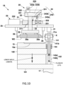
- the lower mold 15 is lowered by the clamping mechanism 17, and the plunger 142a is lifted with respect to the lower mold 15 by the transfer mechanism 142 as illustrated in FIG. 10 .
- the pot block 141 is also lowered.
- the plunger 142a is lifted with respect to the lower mold 15 by the transfer mechanism 142, which maintains the height position of the plunger 142a with respect to the second holder 21 regardless of the lowering of the lower mold 15.
- This causes the relative positional relationship between the second holder 21 sucking and holding the unnecessary resin K and the plunger 142a not to change.
- the unnecessary resin K is pushed out of the pot 141a, the amount of elastic deformation of the suction pad 21a of the second holder 21 hardly changes.
- the unnecessary resin K sucked and held by the suction pad 21a of the second holder 21 is peeled off from the pot block 141 and lifted.
- the unloader 19 exits from the upper mold 16 and the lower mold 15, conveys the resin molded product W2 to the storage part 18 of the storage module 100C, and conveys the unnecessary resin K to a disposal box (not illustrated).
- the resin molding apparatus 100 of the present embodiment in which the resin molded product W2 held by the first holder 20 moves upward under the overhang 141b, and thereafter, the resin molded product W2 moves outward with respect to the overhang 141b, can reliably unload the resin molded product W2 from the lower mold 15 even when, for example, the resin molded product W2 is formed with a resin sealing part formed on the lower side of the object to be molded W1 or when a release film is provided on the lower mold 15.
- the lower mold 15 is lowered by the clamping mechanism 17, and at the same time, the plunger 142a is lifted with respect to the lower mold 15 by the transfer mechanism 142 in a state where the resin molded product W2 is moved outward with respect to the overhang 141b, and the second holder 21 is in contact with the unnecessary resin K on the pot block 141.
- the unnecessary resin K is peeled off from the pot block 141 in a state where the second holder 21 is in contact with the unnecessary resin K on the pot block 141.
- the present invention is not limited to the above embodiment.
- the second lifting movement mechanism 24 is configured using the second slide member 231 of the horizontal movement mechanism 23, but the second lifting movement mechanism 24 may be provided separately from the horizontal movement mechanism 23 without using the second slide member 231.
- the lower mold 15 has the cavity 15a, but the lower mold 15 may have no cavity 15a.
- the resin molded product W2 can be reliably unloaded from the lower mold 15 in the configuration in which a release film is provided in the lower mold 15.
- the height position of the plunger 142a with respect to the second holder 21 is maintained, but it is not always necessary to maintain the height position of the plunger 142a.
- the height position of the plunger 142a with respect to the second holder 21 may be changed in a range in which the suction pad 21a of the second holder 21 is maintained in contact with the unnecessary resin K.
- the lifting roller member 223a may be provided in the first slide member 221, and the lifting roller contact part 223b may be provided in the second movable body 32.
- the lifting roller member 242a may be provided in the second movable body 32, and the lifting roller contact part 242b may be provided in the second slide member 231.
- the first holder 20 is configured to move in the direction away from the pot block 141 by moving the second slide member 231 in the direction away from the pot block 141, but the first holder 20 may be configured to move in the direction away from the pot block 141 by moving the second slide member 231 in the direction toward the pot block 141.
- the link mechanism 233 is formed of one link arm (for example, the first link arm 233a of the above embodiment).
- the second holder 21 comes into contact with the unnecessary resin K on the pot block 141.
- the second holder 21 may be brought into contact with the unnecessary resin K on the pot block 141 after the resin molded product W2 is lifted by the second lifting movement mechanism 24.
- the conveying claw 26 prevents the resin molded product W2 sucked and held from falling.
- the suction and holding may be released after the resin molded product W2 is lifted, and the resin molded product W2 may be held by the conveying claw 26.
- the conveying claw 26 does not have to be provided as long as the suction and holding is performed at the time of conveyance.
- the present invention can reliably collect the unnecessary resin on the pot block having the overhang while reliably unloading the resin molded product from the lower mold provided with the pot block.
Landscapes
- Engineering & Computer Science (AREA)
- Mechanical Engineering (AREA)
- Manufacturing & Machinery (AREA)
- Robotics (AREA)
- Moulds For Moulding Plastics Or The Like (AREA)
- Injection Moulding Of Plastics Or The Like (AREA)
Abstract
Description
- The present invention relates to a resin molding apparatus and a resin molded product manufacturing method.
- There is an apparatus that has conventionally been considered, in which resin sealing is performed by clamping an upper mold and a lower mold, and injecting a molten resin into a cavity of the upper mold from a space formed between an upper surface of a pot block provided in the lower mold and a lower surface of the upper mold in a state where a part of an object to be molded is sandwiched between an overhang of the pot block and an upper surface of the lower mold, as disclosed in Patent Literature 1, for example.
- In this resin molding apparatus, a resin molded product and an unnecessary resin are unloaded using a conveying apparatus (unloader) having a molded product suction part and an unnecessary resin suction part after resin molding. Here, each of the molded product suction part and the unnecessary resin suction part is formed of a suction pad made of resin.
- Then, the molded product suction part sucks the resin molded product, and the molded product suction part sucking the resin molded product moves horizontally in a direction away from the pot block to move the resin molded product out of the overhang. In addition, in a state where the unnecessary resin suction part is in contact with the unnecessary resin on the pot block, the plunger is lifted to lift the unnecessary resin from the pot block, which causes the unnecessary resin suction part to suck the unnecessary resin. The suction pad of the unnecessary resin suction part elastically deforms and contracts while being in contact with the unnecessary resin when the unnecessary resin is lifted.
- Patent Literature 1:
JP 2022-39709 A - However, for example, in a case of a resin molded product formed by using a lower mold with a cavity, with which a resin sealing part is formed on the lower side of an object to be molded , the resin molded product cannot move horizontally unless the resin sealing part on the lower side is taken out upward from the cavity of the lower mold. When the lower mold has an alignment pin for the substrate (object to be molded ), the resin molded product (substrate) cannot move horizontally unless the resin molded product is moved upward and taken out from the alignment pin. Further, for example, a release film may be provided in the lower mold even in a configuration in which the lower mold has no cavity, and it is not possible to reliably separate the resin molded product and the release film only by sucking the resin molded product with the molded product suction part.
- From these problems, it is conceivable to move upward the molded product suction part sucking the resin molded product and then move the molded product suction part in a direction away from the pot block. Here, to prevent the resin molded product from hitting the overhang when the molded product suction part moves upward, it is conceivable to increase the distance between the overhang of the pot block and the mold surface of the lower mold.
- However, when the distance between the overhang of the pot block and the mold surface of the lower mold is increased, the distance between the upper surface of the pot block and the lower surface of the upper mold becomes relatively small. As a result, the size of the suction pad of the unnecessary resin suction part is restricted, and the elastic deformation amount of the unnecessary resin suction part for taking out the unnecessary resin from the pot cannot be secured, which makes it difficult to stably collect the unnecessary resin.
- The present invention has been made to solve the above problems. A main object of the present invention is to reliably collect an unnecessary resin on a pot block having an overhang while reliably unloading a resin molded product from a lower mold provided with the pot block. Solution to Problem
- That is, a resin molding apparatus according to the present invention includes a mold including an upper mold and a lower mold and having a cavity formed in at least one of the upper mold and the lower mold, a clamping mechanism that clamps the upper mold and the lower mold, a pot block provided in the lower mold and formed with a pot that houses a resin material, a transfer mechanism that moves a plunger in the pot and injects the resin material into the cavity, and a conveying mechanism that unloads a resin molded product after resin molding from the lower mold, wherein the pot block includes an overhang overhanging between at least a part of the resin molded product and the upper mold, the conveying mechanism includes a first holder that holds the resin molded product, a second holder that holds an unnecessary resin on the pot block, a first lifting movement mechanism that lifts the first holder such that the resin molded product held by the first holder moves upward under the overhang, and a horizontal movement mechanism that moves the first holder in a horizontal direction such that the resin molded product held by the first holder moves outward with respect to the overhang in a state where the first holder is lifted by the first lifting movement mechanism, and the lower mold is lowered by the clamping mechanism and the plunger is lifted with respect to the lower mold by the transfer mechanism, in a state where the resin molded product is moved outward with respect to the overhang and the second holder is in contact with the unnecessary resin on the pot block. Advantageous Effects of Invention
- The present invention configured as described above can reliably collect the unnecessary resin on the pot block having the overhang while reliably unloading the resin molded product from the lower mold provided with the pot block.
-
-
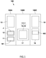
FIG. 1 is a schematic view illustrating a configuration of a resin molding apparatus according to an embodiment of the present invention. -
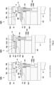
FIG. 2 includes schematic views illustrating a state before clamping (a), a state during clamping (b), and a state after mold opening (c) in a molding module of the embodiment. -
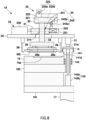
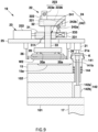
FIG. 3 is a side view schematically illustrating a configuration of a conveying mechanism of the embodiment. -
FIG. 4 is a side view schematically illustrating a lifting operation (first vertical movement) of a first lifting mechanism of the embodiment. -
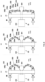
FIG. 5 is a view schematically illustrating a configuration of a horizontal movement mechanism of the embodiment. -
FIG. 6 is a view schematically illustrating an operation of the horizontal movement mechanism of the embodiment. -
FIG. 7 is a side view schematically illustrating a horizontal operation of the horizontal movement mechanism of the embodiment. -
FIG. 8 is a side view schematically illustrating a lifting operation (second vertical movement) of a second lifting mechanism of the same embodiment. -
FIG. 9 is a side view schematically illustrating a state in which the interval between conveying claws is reduced in a conveying apparatus of the embodiment. -
FIG. 10 is a side view schematically illustrating a suction operation for an unnecessary resin of the embodiment. - Next, the technology according to the present invention will be described in more detail with reference to examples. However, the present invention is not limited by the following technology.
- That is, a resin molding apparatus of technology 1 according to the present invention includes a mold including an upper mold and a lower mold and having a cavity formed in at least one of the upper mold and the lower mold, a clamping mechanism that clamps the upper mold and the lower mold, a pot block provided in the lower mold and formed with a pot that houses a resin material, a transfer mechanism that moves a plunger in the pot and injects the resin material into the cavity, and a conveying mechanism that unloads a resin molded product after resin molding from the lower mold, wherein the pot block includes an overhang overhanging between at least a part of the resin molded product and the upper mold, the conveying mechanism includes a first holder that holds the resin molded product, a second holder that holds an unnecessary resin on the pot block, a first lifting movement mechanism that lifts the first holder such that the resin molded product held by the first holder moves upward under the overhang, and a horizontal movement mechanism that moves the first holder in a horizontal direction such that the resin molded product held by the first holder moves outward with respect to the overhang in a state where the first holder is lifted by the first lifting movement mechanism, and the lower mold is lowered by the clamping mechanism and the plunger is lifted with respect to the lower mold by the transfer mechanism, in a state where the resin molded product is moved outward with respect to the overhang and the second holder is in contact with the unnecessary resin on the pot block.
- The resin molding apparatus of the present embodiment, in which the resin molded product held by the first holder moves upward under the overhang, and thereafter, the resin molded product moves outward with respect to the overhang, can reliably unload the resin molded product from the lower mold even when, for example, the resin molded product is formed with a resin sealing part formed on the lower side of the object to be molded or when a release film is provided on the lower mold.
- In addition, the lower mold is lowered, and at the same time, the plunger is lifted with respect to the lower mold in a state where the resin molded product is moved outward with respect to the overhang, and the second holder is in contact with the unnecessary resin on the pot block. Thus, the unnecessary resin is peeled off from the pot block in a state where the second holder is in contact with the unnecessary resin on the pot block. As a result, it is possible to prevent collection failure caused by inclination of the unnecessary resin on the pot block.
- In the resin molding apparatus of technology 2 according to the present invention, in addition to the configuration of technology 1 described above, the second holder includes a bellows type suction pad for sucking the unnecessary resin.
- This configuration allows the effect of the configuration of technology 1 described above (the configuration in which the lower mold is lowered and the plunger is lifted with respect to the lower mold) to be further remarkable. That is, it is not necessary to use a suction pad having a large amount of elastic deformation, and the remaining amount (pot remaining portion) of the resin remaining in the pot is not restricted by the amount of elastic deformation of the suction pad.
- The "remaining amount of the resin remaining in the pot (pot remaining portion)" deals with a variation in the resin amount or a change in the resin amount due to the presence or absence of an electronic component. For example, when the resin molding is performed using the same amount of resin material in dummy molding without an electronic component and mounting molding with an electronic component, the change in the resin material due to the presence or absence of the electronic component is absorbed by the pot remaining portion.
- In a resin molding apparatus of technology 3 according to the present invention, in addition to the configuration of technology 1 or 2 described above, a height position of the plunger with respect to the second holder is maintained by the transfer mechanism lifting the plunger with respect to the lower mold.
- This configuration causes the relative positional relationship between the second holder in contact with the unnecessary resin and the plunger not to change. For example, in a case where the second holder has a suction pad, the amount of elastic deformation of the suction pad hardly changes when the unnecessary resin is pushed out of the pot. Thus, it is not necessary to use a suction pad having a large amount of elastic deformation. In addition, since the position of the unnecessary resin hardly changes when the unnecessary resin is pushed out of the pot, the unnecessary resin can be reliably held by the second holder, and the unnecessary resin on the pot block can be reliably collected.
- In a resin molding apparatus of technology 4 according to the present invention, in addition to the configuration of any one of technologies 1 to 3 described above, the conveying mechanism further includes a base member in which the first holder is movably provided, a first movable body that moves in a horizontal direction with respect to the base member, a second movable body that moves in a horizontal direction together with the first movable body and moves in an up-down direction with respect to the first movable body, and a coupling member that couples the second movable body and the first holder.
- With such a configuration, when the first movable body moves in the horizontal direction with respect to the base member, the second movable body moves in the horizontal direction together with the first movable body, and the first holder coupled to the second movable body moves in the horizontal direction. When the second movable body moves in the up-down direction with respect to the first movable body, the first holder coupled to the second movable body moves in the up-down direction.
- As a specific embodiment of the first lifting movement mechanism, the following is conceivable.
- That is, in a resin molding apparatus of technology 5 according to the present invention, in addition to the configuration of technology 4 described above, the first lifting movement mechanism includes a first slide member that moves in a horizontal direction with respect to the base member, and a first lifting cam mechanism that moves the first holder upward by moving the second movable body upward along with the movement of the first slide member.
- As a specific embodiment of the horizontal movement mechanism, the following is conceivable.
- That is, in a resin molding apparatus of technology 6 according to the present invention, in addition to the configuration of technology 4 or 5 described above, the horizontal movement mechanism includes a second slide member that moves in a horizontal direction with respect to the base member, and a link mechanism that moves the first movable body in a direction away from the pot block along with the movement of the second slide member.
- With this configuration, the horizontal movement mechanism includes the link mechanism, and thus the movement of the second slide member can be transmitted to the movement of the holder without difficulty.
- As a specific embodiment of the conveying mechanism, the following is conceivable.
- That is, in a resin molding apparatus of technology 7 according to the present invention, in addition to the configuration of any one of technologies 1 to 6 described above, the conveying mechanism further includes a second lifting movement mechanism that lifts the first holder in a state where the resin molded product is moved outward with respect to the overhang by the horizontal movement mechanism.
- In a resin molding apparatus of technology 8 according to the present invention, in addition to the configuration of technology 7 described above, the conveying mechanism further includes a second lifting movement mechanism that lifts the first holder in a state where the resin molded product is moved outward with respect to the overhang by the horizontal movement mechanism, and the second lifting movement mechanism includes a second lifting cam mechanism that moves the first holder upward by moving the second movable body upward along with the horizontal movement of the second slide member.
- With this configuration, the second lifting movement mechanism can be configured using the second slide member of the horizontal movement mechanism, and thus, not only the configuration can be simplified but also the cost can be reduced.
- In a resin molding apparatus of technology 9 according to the present invention, in addition to the configuration of technology 7 or 8 described above, the conveying mechanism further includes a conveying claw that hooks and holds the resin molded product, and the resin molded product is held by using the conveying claw in a state where the first holder is lifted by the second lifting movement mechanism.
- This configuration can stably unload the resin molded product and prevent the resin molded product from falling. In addition, since the resin molded product is held by using the conveying claw in a state where the first holder is lifted by the second lifting movement mechanism, the lower surface of the resin molded product can be held. Further, it is possible to prevent the conveying claw from coming into contact with the mold surface of the lower mold and giving a scratch.
- In a resin molding apparatus of technology 10 according to the present invention, in addition to the configuration of any one of technologies 1 to 9 described above, the cavity is formed in the lower mold, and the first lifting movement mechanism lifts the first holder until a resin sealing part formed by the cavity of the lower mold is positioned above a parting line of the lower mold.
- A resin molded product manufacturing method using the resin molding apparatus according to any one of technologies 1 to 10 described above, the resin molded product manufacturing method including a molding step of performing resin molding on an object to be molded , and an unloading step of unloading a resin molded product on which resin molding has been performed, is also one aspect of the present invention.
- Hereinafter, an embodiment of a resin molding apparatus according to the present invention will be described with reference to the drawings. All the drawings described below are schematically illustrated with appropriate omission or exaggeration for easy understanding. The same components are denoted by the same reference numerals, and the description thereof will be omitted as appropriate.
- A
resin molding apparatus 100 of the present embodiment performs resin molding of an object to be molded W1 to which an electronic component Wx is fixed through transfer molding using a resin material J. - Here, the object to be molded W1 is, for example, a metal substrate, a resin substrate, a glass substrate, a ceramic substrate, a circuit substrate, a semiconductor substrate, a lead frame, a silicon wafer, a glass wafer, or the like, and the presence or absence of wiring is irrelevant. The resin material J for resin molding is, for example, a composite material containing a thermosetting resin, and the form of the resin material J is granular, powder, liquid, sheet, tablet, or the like. Examples of the electronic component Wx include an electronic element such as a semiconductor chip, a resistance element, or a capacitor element, and an electronic component in which at least one of these electronic elements is resin-sealed.
- Specifically, as illustrated in
FIG. 1 , theresin molding apparatus 100 includes, as components, asupply module 100A that supplies the object to be molded W1 before molding and the resin material J, amolding module 100B that performs resin molding, and astorage module 100C that houses an object to be molded W2 after molding (hereinafter, resin molded product W2). Thesupply module 100A, themolding module 100B, and thestorage module 100C can be attached to and detached from each other with respect to other components, and can be replaced with each other. - The
supply module 100A includes an object to be moldedsupply unit 11 that supplies the object to be molded W1, a resinmaterial supply unit 12 that supplies the resin material J, and a conveying mechanism 13 (hereinafter, loader 13) that receives the object to be molded W1 from the object to be moldedsupply unit 11, conveys the object to be molded W1 to themolding module 100B, receives the resin material J from the resinmaterial supply unit 12, and conveys the object to be molded W1 to themolding module 100B. - The
loader 13 moves between thesupply module 100A and themolding module 100B, and it moves along a rail (not illustrated) provided across thesupply module 100A and themolding module 100B. - As illustrated in
FIG. 2 , themolding module 100B includes alower mold 15 provided with aresin injection unit 14 and formed with acavity 15a into which the resin material J is injected, anupper mold 16 provided to face thelower mold 15 and formed with acavity 16a into which the resin material J is injected, and aclamping mechanism 17 that clamps thelower mold 15 and theupper mold 16. Thelower mold 15 is provided on amovable platen 101 via alower platen 102. Themovable platen 101 is moved up and down by theclamping mechanism 17. Theupper mold 16 is provided on an upper fixed platen (not illustrated) via anupper platen 103.FIG. 2 illustrates only one side (left side) of theresin injection unit 14, and the other side (right side) is omitted. The configuration of the other side inFIG. 2 is the same as the configuration of the one side. - The
resin injection unit 14 of the present embodiment includes apot block 141 in which apot 141a that houses the resin material J is formed, and atransfer mechanism 142 having aplunger 142a provided in thepot 141a. Here, thetransfer mechanism 142 includes theplunger 142a for pressure-feeding the resin material J housed in thepot 141a, and aplunger drive unit 142b that drives theplunger 142a. Theplunger 142a pressure-feeds the resin material J heated and melted in thepot 141a. - The
pot block 141 is provided in thelower mold 15, and is elastically supported by anelastic member 144 so as to be movable up and down with respect to thelower mold 15. At the upper end of thepot block 141, anoverhang 141b overhanging on a mold surface which is the upper surface of thelower mold 15 is formed. In a state where theupper mold 16 and thelower mold 15 are clamped, the upper surface of theoverhang 141b comes into contact with theupper mold 16, and the lower surface of theoverhang 141b sandwiches the object to be molded W1 with the the mold surface of the lower mold 15 (seeFIG. 2(b) ). With theoverhang 141b, a part where at least a part of the resin molded product W2 is overhung between theupper mold 16 and theoverhang 141b (seeFIG. 2 (c) ) is formed after resin molding. Further, on the upper surface of thepot block 141, a cal part and a gate part (both not illustrated) serving as a resin flow path for introducing the resin material J injected from thepot 141a into thecavities - The
cavity 15a of thelower mold 15 is for resin-sealing the lower surface of the object to be molded W1, and thecavity 16a of theupper mold 16 is for resin-sealing the upper surface of the object to be molded W1. Here, the electronic component Wx of the object to be molded W1 is housed in at least one of thecavity 15a of thelower mold 15 and thecavity 16a of theupper mold 16. - In the
upper mold 16, arecess 16b is formed in a portion facing theoverhang 141b of thepot block 141, and arunner 16c that connects the cal part and the gate part of thepot block 141 and thecavities lower mold 15, a runner part that connects the cal part and the gate part of thepot block 141 and thecavities lower mold 15 or theupper mold 16 is formed with an air vent on the opposite side from thepot block 141. - As illustrated in
FIG. 2(b) , when thelower mold 15 and theupper mold 16 are clamped by theclamping mechanism 17, thepot block 141 lowers, and the pot-side end of the object to be molded W1 is sandwiched between the lower surface of theoverhang 141b of thepot block 141 and the upper surface of thelower mold 15. When the resin material J melted by theplunger 142a is injected into thecavities - The
storage module 100C is provided with astorage part 18 that stores the resin molded product W2, and a conveying mechanism 19 (hereinafter, unloader 19) that receives the resin molded product W2 from themolding module 100B and conveys the resin molded product W2 to thestorage part 18. - The
unloader 19 moves between themolding module 100B and thestorage module 100C, and it moves along a rail (not illustrated) provided across themolding module 100B and thestorage module 100C. Details of theunloader 19 will be described later. - A basic operation of the
resin molding apparatus 100 will be briefly described with reference toFIG. 2 . The following operation is performed, for example, by a control unit COM provided in thesupply module 100A controlling each unit. - In a state where the
lower mold 15 and theupper mold 16 are open, the object to be molded W1 is conveyed by theloader 13 and placed on thelower mold 15 as illustrated inFIG. 2(a) . At this time, theupper mold 16 and thelower mold 15 are heated to a temperature at which the resin material J can be melted and cured. The resin material J is conveyed by theloader 13 and housed in thepot 141a of thepot block 141. - When the
lower mold 15 is lifted by theclamping mechanism 17 in this state, as illustrated inFIG. 2(b) , thepot block 141 comes into contact with theupper mold 16 and lowers with respect to thelower mold 15, and the lower surface of theoverhang 141b comes into contact with the pot-side end of the object to be molded W1. The lower surface of theupper mold 16 comes into contact with the vent-side end of the object to be molded W1. This causes thelower mold 15 and theupper mold 16 to be clamped. When theplunger drive unit 142b lifts theplunger 142a after the clamping, the molten resin material J in thepot 141a is injected into thecavities cavities clamping mechanism 17 as illustrated inFIG. 2(c) . This mold opening causes thepot block 141 to lift with respect to thelower mold 15 and theelastic member 144 of thepot block 141 to extend. When theplunger 142a lifts in accordance with the extension of theelastic member 144, an unnecessary resin K on thepot block 141 separates from the resin molded product W2 (gate break). Thereafter, the resin molded product W2 is unloaded by theunloader 19 and conveyed to thestorage part 18. - Next, a specific configuration of the
unloader 19 in the present embodiment will be described with reference toFIGS. 3 to 10 .FIGS. 3 and6 to 10 illustrate only one side (left side) of thepot block 141, and the other side (right side) is omitted. The state of the other side is the same as the state of the one side in each drawing. - As illustrated in
FIGS. 3 to 10 , theunloader 19 includes afirst holder 20 that holds the resin molded product W2, asecond holder 21 that holds the unnecessary resin K on thepot block 141, a firstlifting movement mechanism 22 that lifts thefirst holder 20 such that the resin molded product W2 held by thefirst holder 20 moves upward under theoverhang 141b, ahorizontal movement mechanism 23 that horizontally moves thefirst holder 20 such that the resin molded product W2 held by thefirst holder 20 moves outward with respect to theoverhang 141b in a state where thefirst holder 20 is lifted by the firstlifting movement mechanism 22, and a secondlifting movement mechanism 24 that lifts thefirst holder 20 in a state where the resin molded product W2 is moved outward with respect to theoverhang 141b by thehorizontal movement mechanism 23. - The
first holder 20 holds the resin molded product W2 from which the unnecessary resin K on thepot block 141 has been separated. The holder includes a moldedproduct suction pad 20a that sucks the resin molded product W2 placed on thelower mold 15. The moldedproduct suction pad 20a is provided on the lower surface of thefirst holder 20, and a suction mechanism (not illustrated) for sucking the resin molded product W2 is connected to the moldedproduct suction pad 20a. The moldedproduct suction pad 20a of the present embodiment is a bellows suction pad. The suction mechanism includes, for example, a suction flow path formed inside thefirst holder 20 and a suction pump connected to the suction flow path. - The
second holder 21 includes an unnecessaryresin suction pad 21a that sucks the unnecessary resin K on thepot block 141. The unnecessaryresin suction pad 21a is provided on the lower surface of thesecond holder 21, and a suction mechanism (not illustrated) for sucking the unnecessary resin K is connected to the unnecessaryresin suction pad 21a. The unnecessaryresin suction pad 21a of the present embodiment is a bellows type suction pad. The suction mechanism includes, for example, a suction flow path formed inside thesecond holder 21 and a suction pump connected to the suction flow path. - The
first holder 20 and thesecond holder 21 are provided in thebase member 25. Specifically, thefirst holder 20 is movably provided on thebase member 25, and thesecond holder 21 is fixed to thebase member 25. Thesecond holder 21 may be movably provided on thebase member 25. - As a configuration that allows the
first holder 20 to move to thebase member 25, theunloader 19 includes a firstmovable body 31 that moves in the horizontal direction with respect to thebase member 25, a secondmovable body 32 that moves in the horizontal direction together with the firstmovable body 31 and moves in an up-down direction with respect to the firstmovable body 31, and acoupling member 33 that couples the secondmovable body 32 and thefirst holder 20. - The first
movable body 31 has, for example, a flat plate shape that moves in the horizontal direction on thebase member 25. The firstmovable body 31 is provided to be movable in a direction toward or away from thepot block 141 with respect to thebase member 25 using a guide part (not illustrated). The guide part includes a rail provided in thebase member 25 in a front-back direction to move back and forth with respect to thepot block 141, and a slider provided in the firstmovable body 31 to move on the rail. - The second
movable body 32 has, for example, a flat plate shape that moves in an up-down direction with respect to the firstmovable body 31. The secondmovable body 32 is provided with the firstmovable body 31 sandwiched between thefirst holder 20 and the secondmovable body 32. - The
coupling member 33 coupling the secondmovable body 32 and thefirst holder 20 is provided so as to be movable up and down with respect to the firstmovable body 31 through a throughhole 31h formed in the firstmovable body 31. Here, one or a plurality ofcoupling members 33 are provided, and when a plurality ofcoupling members 33 are provided, the secondmovable body 32 and thefirst holder 20 are coupled at a plurality of positions. The throughhole 31h formed in the firstmovable body 31 and thecoupling member 33 function as aguide part 241 that guides the movement of the secondmovable body 32 in the up-down direction. - With such a configuration, when the first
movable body 31 moves in the horizontal direction with respect to thebase member 25, the secondmovable body 32 moves in the horizontal direction together with the firstmovable body 31, and thefirst holder 20 coupled to the secondmovable body 32 moves in the horizontal direction. When the secondmovable body 32 moves in the up-down direction with respect to the firstmovable body 31, thefirst holder 20 coupled to the secondmovable body 32 moves in the up-down direction. - The
base member 25 is provided to be movable in the horizontal direction and the up-down direction along a rail (not illustrated). Thebase member 25 is provided with a conveyingclaw 26 for preventing the resin molded product W2 held by thefirst holder 20 from falling or holding the resin molded product W2. A pair of conveyingclaws 26 is provided so as to hook both ends of the resin molded product W2, and the interval between the conveyingclaws 26 is increased or reduced by a drive unit (not illustrated). The distance between the conveyingclaws 26 is reduced by the drive unit so as to hook the resin molded product W2, and the distance between the conveyingclaws 26 is increased so as not to block the lifting and lowering movement of the resin molded product W2 moved by a secondlifting movement mechanism 24. - The first
lifting movement mechanism 22 moves thefirst holder 20 up and down, and linearly moves the resin molded product W2 held by thefirst holder 20 upward under theoverhang 141b. During the movement with the firstlifting movement mechanism 22, thefirst holder 20 is in a state of sucking and holding the resin molded product W2. - Here, the first
lifting movement mechanism 22 lifts thefirst holder 20 until the lower resin sealing part formed by thecavity 15a of thelower mold 15 is positioned above the parting line (mold surface) of the lower mold 15 (seeFIG. 4 ). The lifting amount of thefirst holder 20 lifted by the firstlifting movement mechanism 22 is such that the resin molded product W2 does not come into contact with theoverhang 141b of thepot block 141. The height position of theoverhang 141b of thepot block 141 with respect to thelower mold 15 is set to such an extent that the resin molded product W2 lifted by the firstlifting movement mechanism 22 does not come into contact with thepot block 141. - Specifically, as illustrated in
FIGS. 3 ,4 , and7 to 10 , the firstlifting movement mechanism 22 includes afirst slide member 221 that moves in the horizontal direction with respect to thebase member 25, afirst drive unit 222 that moves thefirst slide member 221, and a firstlifting cam mechanism 223 that moves thefirst holder 20 upward by moving the secondmovable body 32 upward along with the movement of thefirst slide member 221. Thefirst slide member 221 of the present embodiment is configured to move in a direction toward or away from thepot block 141. Thefirst drive unit 222 is, for example, a block including an air cylinder (not illustrated), and thefirst slide member 221 and thefirst drive unit 222 are configured by an air slide table. - As illustrated in
FIGS. 3 ,4 , and7 to 10 , the firstlifting cam mechanism 223 includes a liftingroller member 223a provided in the secondmovable body 32, and a liftingroller contact part 223b provided in thefirst slide member 221 to move the liftingroller member 223a along with the movement of thefirst slide member 221. The liftingroller contact part 223b has an inclined surface that comes into contact with the liftingroller member 223a and moves the liftingroller member 223a upward as thefirst slide member 221 moves in the direction toward thepot block 141. The liftingroller member 223a may be formed of, for example, a rolling element (bearing) or a bush rotatably provided on the secondmovable body 32. - When the
first slide member 221 is moved in the direction toward thepot block 141 by such a firstlifting movement mechanism 22, the liftingroller member 223a in contact with the inclined surface of the liftingroller contact part 223b moves upward (seeFIG. 4 ). This causes the secondmovable body 32 and thefirst holder 20 coupled to the secondmovable body 32 to move upward with respect to the first movable body 31 (first vertical movement). - When the
first slide member 221 is moved in the direction away from thepot block 141, the secondmovable body 32 and thefirst holder 20 coupled to the secondmovable body 32 move downward with respect to the firstmovable body 31 by its own weight (seeFIG. 3 ). - The
horizontal movement mechanism 23 linearly moves thefirst holder 20 holding the resin molded product W2 in a direction away from thepot block 141. As described above, since the resin molded product W2 is positioned above the parting line (mold surface) of thelower mold 15 by the firstlifting movement mechanism 22, thehorizontal movement mechanism 23 linearly moves the resin molded product W2 sucked and held by thesuction pad 20a in a direction away from thepot block 141. - Specifically, as illustrated in
FIGS. 3 to 10 , thehorizontal movement mechanism 23 includes asecond slide member 231 that moves in the horizontal direction with respect to thebase member 25, asecond drive unit 232 that moves thesecond slide member 231, and alink mechanism 233 that moves the firstmovable body 31 in a direction away from thepot block 141 along with the movement of thesecond slide member 231. Thesecond slide member 231 of the present embodiment is configured to move in a direction toward or away from thepot block 141. Thesecond drive unit 232 uses, for example, an air cylinder. - As illustrated in
FIGS. 5 and6 , thelink mechanism 233 of the present embodiment is configured to move the first holder 20 (first movable body 31) in a direction away from thepot block 141 as thesecond slide member 231 moves in a direction away from thepot block 141. Here, thelink mechanism 233 includes first andsecond link arms base member 25. Thesecond link arm 233b is configured to rotate in a direction opposite to thefirst link arm 233a along with the rotation of thefirst link arm 233a. - Further, as illustrated in
FIGS. 5 and6 , thehorizontal movement mechanism 23 is provided with a firsthorizontal cam mechanism 234 between thesecond slide member 231 and thelink mechanism 233, and is provided with a secondhorizontal cam mechanism 235 between thelink mechanism 233 and the firstmovable body 31. - The first
horizontal cam mechanism 234 includes a firstroller contact part 234a provided on thesecond slide member 231 and afirst roller member 234b provided on thefirst link arm 233a and moving along the firstroller contact part 234a. The firstroller contact part 234a of the present embodiment includes an inclined surface and a flat surface formed on a side surface of thesecond slide member 231, and is configured such that thefirst roller member 234b slides on the inclined surface and the flat surface. As thefirst roller member 234b moves along the inclined surface of the firstroller contact part 234a, thefirst link arm 233a rotates in one direction (seeFIG. 6(b) ). On the other hand, when thefirst roller member 234b moves along - the flat surface of the first
roller contact part 234a, thefirst link arm 233a maintains its state without rotating (seeFIG. 6(c) ). Thefirst roller member 234b may be formed of, for example, a rolling element (bearing) or a bush rotatably provided at the inner end of thefirst link arm 233a. - The second
horizontal cam mechanism 235 includes a secondroller contact part 235a provided on the firstmovable body 31 and asecond roller member 235b provided on thesecond link arm 233b and moving along the secondroller contact part 235a. Thesecond roller member 235b may be formed of, for example, a rolling element (bearing) or a bush rotatably provided at the outer end of thesecond link arm 233b. The secondroller contact part 235a is provided on the surface of the firstmovable body 31 facing thepot block 141, and is a flat surface in the present embodiment. - With such a
link mechanism 233, when thesecond slide member 231 moves in the direction away from the pot block 141 (FIG. 6(a) → (b)), thefirst roller member 234b moves along the inclined surface of the firstroller contact part 234a of thesecond slide member 231, and thefirst link arm 233a rotates. Then, along with the rotation of thefirst link arm 233a, thesecond link arm 233b rotates in the direction opposite to the first link arm 232a, and thesecond roller member 235b of thesecond link arm 233b pushes the secondroller contact part 235a of the firstmovable body 31 in the direction away from thepot block 141. This causes the firstmovable body 31 to move in the direction away from thepot block 141. Thereafter, when thefirst roller member 234b reaches the flat surface of the firstroller contact part 234a (FIG. 6(b) → (c)), the rotation of thefirst link arm 233a stops, and the movement of the firstmovable body 31 in the horizontal direction stops. - The first
movable body 31 is biased toward thepot block 141 by, for example, anelastic member 28 provided via a T-shapedblock 27, and when thesecond slide member 231 moves toward thepot block 141, the firstmovable body 31 moves toward thepot block 141. - The second
lifting movement mechanism 24 lifts thefirst holder 20 in a state where the resin molded product W2 has been moved outward with respect to theoverhang 141b by thehorizontal movement mechanism 23. The secondlifting movement mechanism 24 linearly moves the secondmovable body 32 moved by thehorizontal movement mechanism 23 upward to move thefirst holder 20 coupled to the secondmovable body 32 upward. - Specifically, as illustrated in
FIGS. 3 ,4 , and7 to 10 , the secondlifting movement mechanism 24 includes aguide part 241 that guides the secondmovable body 32 in the vertical direction (up-down direction), and a secondlifting cam mechanism 242 that moves the secondmovable body 32 upward along with the horizontal movement of thesecond slide member 231 of thehorizontal movement mechanism 23. - The
guide part 241 of the present embodiment is formed of a throughhole 31h of the firstmovable body 31 and acoupling member 33 by inserting thecoupling member 33 into the throughhole 31h. Theguide part 241 may include a rail provided in the firstmovable body 31 in the up-down direction and a slider provided in the second movable body to move on the rail. - As illustrated in
FIGS. 3 ,4 , and7 to 10 , the secondlifting cam mechanism 242 includes a liftingroller member 242a provided on thesecond slide member 231, and a liftingroller contact part 242b provided on the secondmovable body 32 and moving along with the movement of the liftingroller member 242a. The liftingroller contact part 242b has an inclined surface provided such that the liftingroller contact part 242b moves upward as the liftingroller member 242a moves in the direction away from thepot block 141. - When the
second slide member 231 moves in the direction away from thepot block 141 because of such a second lifting movement mechanism 24 (FIG. 6(b) → (c)), the liftingroller member 242a comes into contact with the inclined surface of the liftingroller contact part 242b (seeFIG. 7 ), and the liftingroller contact part 242b moves upward (seeFIG. 8 ). This causes the secondmovable body 32 and thefirst holder 20 coupled to the secondmovable body 32 to move upward with respect to the first movable body 31 (second vertical movement). - When the
second slide member 231 moves toward thepot block 141, the secondmovable body 32 and thefirst holder 20 coupled to the secondmovable body 32 move downward with respect to the firstmovable body 31 by its own weight (seeFIG. 7 ). - Next, the unloading operation of the
unloader 19 will be described with reference toFIGS. 3 to 10 . - In a state where the
upper mold 16 and thelower mold 15 are open, as illustrated inFIG. 3 , theunloader 19 is moved above thelower mold 15, and then lowered to a predetermined position for sucking and holding the resin molded product W2 and the unnecessary resin K. Then, the resin molded product W2 is sucked and held by thesuction pad 20a of thefirst holder 20, and the unnecessary resin K is sucked and held by thesuction pad 21a of thesecond holder 21. The distance between the conveyingclaws 26 is increased so as not to block the suction and holding of the resin molded product W2. Thesecond holder 21 provided on thebase member 25 comes into contact with the unnecessary resin K remaining on the upper surface of thepot block 141. - Then, as illustrated in
FIG. 4 , when thefirst slide member 221 of the firstlifting movement mechanism 22 is moved, the secondmovable body 32 is lifted along with the movement. Specifically, when thefirst slide member 221 is moved in the direction toward thepot block 141, the secondmovable body 32 is moved upward by the firstlifting cam mechanism 223. When the secondmovable body 32 moves upward, thefirst holder 20 coupled to the secondmovable body 32 moves upward (first vertical movement). This first vertical movement causes the lower resin sealing part of the resin molded product W2 held by thefirst holder 20 to be positioned above the parting line (mold surface) of thelower mold 15. When a release film is provided in thelower mold 15, the lower resin sealing part is positioned above the upper surface of the release film on the parting line. - Next, as illustrated in
FIG. 7 , the firstmovable body 31 is moved in a direction away from thepot block 141 by thehorizontal movement mechanism 23. Specifically, when thesecond slide member 231 of thehorizontal movement mechanism 23 is moved in the direction away from thepot block 141, the firstmovable body 31 is moved in the direction away from thepot block 141 by thelink mechanism 233 and thehorizontal cam mechanisms 234 and 235 (FIG. 6(a) → (b)). When the firstmovable body 31 moves, the secondmovable body 32 and thefirst holder 20 also move simultaneously together with the firstmovable body 31. This movement causes the resin molded product W2 to move outward with respect to theoverhang 141b of thepot block 141. - Further, as illustrated in
FIG. 8 , when thesecond slide member 231 of thehorizontal movement mechanism 23 is moved, the secondmovable body 32 is lifted along with the movement. Specifically, when thesecond slide member 231 is moved in the direction away from thepot block 141 from the state ofFIG. 7 (FIG. 6(b) → (c)), the secondmovable body 32 is moved upward by the secondlifting cam mechanism 242. When the secondmovable body 32 moves upward, thefirst holder 20 coupled to the secondmovable body 32 also moves upward at the same time (second vertical movement). This second vertical movement causes the resin molded product W2 to move to such a height that the resin molded product W2 can be held by the conveyingclaws 26. Then, as illustrated inFIG. 9 , the interval between the conveyingclaws 26 is reduced so that the conveyingclaws 26 are positioned below the resin molded product W2. When the second vertical movement ends, the movement of thesecond slide member 231 ends. - As described above, after the resin molded product W2 is moved outward with respect to the
overhang 141b and thesecond holder 21 is brought into contact with the unnecessary resin K on thepot block 141, thelower mold 15 is lowered by theclamping mechanism 17, and theplunger 142a is lifted with respect to thelower mold 15 by thetransfer mechanism 142 as illustrated inFIG. 10 . When thelower mold 15 is lowered, thepot block 141 is also lowered. - In the present embodiment, the
plunger 142a is lifted with respect to thelower mold 15 by thetransfer mechanism 142, which maintains the height position of theplunger 142a with respect to thesecond holder 21 regardless of the lowering of thelower mold 15. This causes the relative positional relationship between thesecond holder 21 sucking and holding the unnecessary resin K and theplunger 142a not to change. In other words, when the unnecessary resin K is pushed out of thepot 141a, the amount of elastic deformation of thesuction pad 21a of thesecond holder 21 hardly changes. Then, by the above operation, the unnecessary resin K sucked and held by thesuction pad 21a of thesecond holder 21 is peeled off from thepot block 141 and lifted. - In this manner, when the
first holder 20 sucks and holds the resin molded product W2 andsecond holder 21 sucks and holds the unnecessary resin K, theunloader 19 exits from theupper mold 16 and thelower mold 15, conveys the resin molded product W2 to thestorage part 18 of thestorage module 100C, and conveys the unnecessary resin K to a disposal box (not illustrated). - <Effects of present embodiment>
- The
resin molding apparatus 100 of the present embodiment, in which the resin molded product W2 held by thefirst holder 20 moves upward under theoverhang 141b, and thereafter, the resin molded product W2 moves outward with respect to theoverhang 141b, can reliably unload the resin molded product W2 from thelower mold 15 even when, for example, the resin molded product W2 is formed with a resin sealing part formed on the lower side of the object to be molded W1 or when a release film is provided on thelower mold 15. - In addition, the
lower mold 15 is lowered by theclamping mechanism 17, and at the same time, theplunger 142a is lifted with respect to thelower mold 15 by thetransfer mechanism 142 in a state where the resin molded product W2 is moved outward with respect to theoverhang 141b, and thesecond holder 21 is in contact with the unnecessary resin K on thepot block 141. Thus, the unnecessary resin K is peeled off from thepot block 141 in a state where thesecond holder 21 is in contact with the unnecessary resin K on thepot block 141. As a result, it is possible to prevent collection failure caused by inclination of the unnecessary resin K on thepot block 141. - The present invention is not limited to the above embodiment.
- For example, in the above embodiment, the second
lifting movement mechanism 24 is configured using thesecond slide member 231 of thehorizontal movement mechanism 23, but the secondlifting movement mechanism 24 may be provided separately from thehorizontal movement mechanism 23 without using thesecond slide member 231. - In the above embodiment, the
lower mold 15 has thecavity 15a, but thelower mold 15 may have nocavity 15a. In this case as well, the resin molded product W2 can be reliably unloaded from thelower mold 15 in the configuration in which a release film is provided in thelower mold 15. - In the above embodiment, when the
lower mold 15 is lowered to push out the unnecessary resin K from thepot 141a, the height position of theplunger 142a with respect to thesecond holder 21 is maintained, but it is not always necessary to maintain the height position of theplunger 142a. For example, the height position of theplunger 142a with respect to thesecond holder 21 may be changed in a range in which thesuction pad 21a of thesecond holder 21 is maintained in contact with the unnecessary resin K. - In the first
lifting cam mechanism 223 of the firstlifting movement mechanism 22 of the embodiment, the liftingroller member 223a may be provided in thefirst slide member 221, and the liftingroller contact part 223b may be provided in the secondmovable body 32. In the secondlifting cam mechanism 242 of the secondlifting movement mechanism 24, the liftingroller member 242a may be provided in the secondmovable body 32, and the liftingroller contact part 242b may be provided in thesecond slide member 231. - Further, in the above embodiment, the
first holder 20 is configured to move in the direction away from thepot block 141 by moving thesecond slide member 231 in the direction away from thepot block 141, but thefirst holder 20 may be configured to move in the direction away from thepot block 141 by moving thesecond slide member 231 in the direction toward thepot block 141. In this case, for example, it is conceivable that thelink mechanism 233 is formed of one link arm (for example, thefirst link arm 233a of the above embodiment). - In the above embodiment, when the
unloader 19 is lowered to the predetermined position for sucking and holding the resin molded product W2, thesecond holder 21 comes into contact with the unnecessary resin K on thepot block 141. However, thesecond holder 21 may be brought into contact with the unnecessary resin K on thepot block 141 after the resin molded product W2 is lifted by the secondlifting movement mechanism 24. - In the above embodiment, the conveying
claw 26 prevents the resin molded product W2 sucked and held from falling. However, the suction and holding may be released after the resin molded product W2 is lifted, and the resin molded product W2 may be held by the conveyingclaw 26. The conveyingclaw 26 does not have to be provided as long as the suction and holding is performed at the time of conveyance. - The present invention is not limited to the above embodiments, and it is needless to say that various modifications can be made without departing from the gist of the present invention.
- The present invention can reliably collect the unnecessary resin on the pot block having the overhang while reliably unloading the resin molded product from the lower mold provided with the pot block.
-
- 100
- resin molding apparatus
- J
- resin material
- W1
- object to be molded
- W2
- resin molded product
- K
- unnecessary resin
- 141
- pot block
- 141a
- pot
- 141b
- overhang
- 142
- transfer mechanism
- 142a
- plunger
- 15
- lower mold
- 15a
- cavity
- 16
- upper mold
- 16a
- cavity
- 17
- clamping mechanism
- 19
- conveying mechanism (unloader)
- 20
- first holder
- 20a
- molded product suction pad
- 21
- second holder
- 21a
- unnecessary resin suction pad
- 22
- first lifting movement mechanism
- 221
- first slide member
- 223
- first lifting cam mechanism
- 23
- horizontal movement mechanism
- 231
- second slide member
- 233
- link mechanism
- 24
- second lifting movement mechanism
- 242
- second lifting cam mechanism
- 25
- base member
- 26
- conveying claw
- 31
- first movable body
- 32
- second movable body
- 33
- coupling member
Claims (10)
- A resin molding apparatus comprising:a mold including an upper mold and a lower mold and having a cavity formed in at least one of the upper mold and the lower mold;a clamping mechanism that clamps the upper mold and the lower mold;a pot block provided in the lower mold and formed with a pot that houses a resin material;a transfer mechanism that moves a plunger in the pot and injects the resin material into the cavity; anda conveying mechanism that unloads a resin molded product after resin molding from the lower mold,whereinthe pot block includes an overhang overhanging between at least a part of the resin molded product and the upper mold,the conveying mechanism includes:a first holder that holds the resin molded product;a second holder that holds an unnecessary resin on the pot block;a first lifting movement mechanism that lifts the first holder such that the resin molded product held by the first holder moves upward under the overhang; anda horizontal movement mechanism that moves the first holder in a horizontal direction such that the resin molded product held by the first holder moves outward with respect to the overhang in a state where the first holder is lifted by the first lifting movement mechanism, andthe lower mold is lowered by the clamping mechanism and the plunger is lifted with respect to the lower mold by the transfer mechanism, in a state where the resin molded product is moved outward with respect to the overhang and the second holder is in contact with the unnecessary resin on the pot block.
- The resin molding apparatus according to claim 1, wherein a height position of the plunger with respect to the second holder is maintained by the transfer mechanism lifting the plunger with respect to the lower mold.
- The resin molding apparatus according to claim 1 or 2, wherein the conveying mechanism further including:a base member in which the first holder is movably provided;a first movable body that moves in a horizontal direction with respect to the base member;a second movable body that moves in a horizontal direction together with the first movable body and moves in an up-down direction with respect to the first movable body; anda coupling member that couples the second movable body and the first holder.
- The resin molding apparatus according to claim 3, wherein
the first lifting movement mechanism includes:a first slide member that moves in a horizontal direction with respect to the base member; anda first lifting cam mechanism that moves the first holder upward by moving the second movable body upward along with the movement of the first slide member. - The resin molding apparatus according to claim 3 or 4, wherein
the horizontal movement mechanism includes:a second slide member that moves in a horizontal direction with respect to the base member; anda link mechanism that moves the first movable body in a direction away from the pot block along with the movement of the second slide member. - The resin molding apparatus according to any one of claims 1 to 5, wherein the conveying mechanism further includes a second lifting movement mechanism that lifts the first holder in a state where the resin molded product is moved outward with respect to the overhang by the horizontal movement mechanism.
- The resin molding apparatus according to claim 5, whereinthe conveying mechanism further includes a second lifting movement mechanism that lifts the first holder in a state where the resin molded product is moved outward with respect to the overhang by the horizontal movement mechanism, andthe second lifting movement mechanism includes a second lifting cam mechanism that moves the first holder upward by moving the second movable body upward along with the horizontal movement of the second slide member.
- The resin molding apparatus according to claim 6 or 7, whereinthe conveying mechanism further includes a conveying claw that hooks and holds the resin molded product, andthe resin molded product is held by using the conveying claw in a state where the first holder is lifted by the second lifting movement mechanism.
- The resin molding apparatus according to any one of claims 1 to 8, whereinthe cavity is formed in the lower mold, andthe first lifting movement mechanism lifts the first holder until a resin sealing part formed by the cavity of the lower mold is positioned above a parting line of the lower mold.
- A resin molded product manufacturing method using the resin molding apparatus according to any one of claims 1 to 9, the resin molded product manufacturing method comprising:a molding step of performing resin molding on an object to be molded; andan unloading step of unloading a resin molded product on which resin molding has been performed.
Applications Claiming Priority (2)
| Application Number | Priority Date | Filing Date | Title |
|---|---|---|---|
| JP2022115273A JP7579829B2 (en) | 2022-07-20 | 2022-07-20 | Resin molding device and method for manufacturing resin molded product |
| PCT/JP2023/020369 WO2024018760A1 (en) | 2022-07-20 | 2023-05-31 | Resin molding device, and method for producing resin molded article |
Publications (2)
| Publication Number | Publication Date |
|---|---|
| EP4541547A1 true EP4541547A1 (en) | 2025-04-23 |
| EP4541547A4 EP4541547A4 (en) | 2025-10-01 |
Family
ID=89617443
Family Applications (1)
| Application Number | Title | Priority Date | Filing Date |
|---|---|---|---|
| EP23842692.8A Pending EP4541547A4 (en) | 2022-07-20 | 2023-05-31 | Resin molding device, and method for producing resin molded article |
Country Status (7)
| Country | Link |
|---|---|
| US (1) | US20260014744A1 (en) |
| EP (1) | EP4541547A4 (en) |
| JP (1) | JP7579829B2 (en) |
| KR (1) | KR20250016323A (en) |
| CN (1) | CN119546433A (en) |
| TW (1) | TWI850010B (en) |
| WO (1) | WO2024018760A1 (en) |
Cited By (1)
| Publication number | Priority date | Publication date | Assignee | Title |
|---|---|---|---|---|
| US20210370565A1 (en) * | 2018-10-19 | 2021-12-02 | Towa Corporation | Conveying apparatus, resin molding apparatus, conveying method, and resin molded product manufacturing method |
Family Cites Families (7)
| Publication number | Priority date | Publication date | Assignee | Title |
|---|---|---|---|---|
| JP6218549B2 (en) * | 2013-10-17 | 2017-10-25 | Towa株式会社 | Semiconductor substrate supply method and semiconductor substrate supply apparatus for semiconductor encapsulated type |
| JP6491508B2 (en) * | 2015-03-23 | 2019-03-27 | Towa株式会社 | Resin sealing device and method of manufacturing resin molded product |
| JP7068094B2 (en) * | 2018-08-10 | 2022-05-16 | アピックヤマダ株式会社 | Work transfer device, resin transfer device and resin molding method |
| JP6655150B1 (en) * | 2018-10-19 | 2020-02-26 | Towa株式会社 | Transfer device, resin molding device, transfer method, and method of manufacturing resin molded product |
| JP7430125B2 (en) * | 2020-08-28 | 2024-02-09 | Towa株式会社 | Molding mold, resin molding equipment, and method for manufacturing resin molded products |
| JP7360369B2 (en) * | 2020-08-28 | 2023-10-12 | Towa株式会社 | Resin molding equipment and method for manufacturing resin molded products |
| JP7341105B2 (en) * | 2020-08-28 | 2023-09-08 | Towa株式会社 | Resin molding equipment and method for manufacturing resin molded products |
-
2022
- 2022-07-20 JP JP2022115273A patent/JP7579829B2/en active Active
-
2023
- 2023-05-31 US US18/995,353 patent/US20260014744A1/en active Pending
- 2023-05-31 EP EP23842692.8A patent/EP4541547A4/en active Pending
- 2023-05-31 CN CN202380052677.7A patent/CN119546433A/en active Pending
- 2023-05-31 KR KR1020247043209A patent/KR20250016323A/en active Pending
- 2023-05-31 WO PCT/JP2023/020369 patent/WO2024018760A1/en not_active Ceased
- 2023-07-05 TW TW112125137A patent/TWI850010B/en active
Cited By (2)
| Publication number | Priority date | Publication date | Assignee | Title |
|---|---|---|---|---|
| US20210370565A1 (en) * | 2018-10-19 | 2021-12-02 | Towa Corporation | Conveying apparatus, resin molding apparatus, conveying method, and resin molded product manufacturing method |
| US12415302B2 (en) * | 2018-10-19 | 2025-09-16 | Towa Corporation | Conveying apparatus, resin molding apparatus, conveying method, and resin molded product manufacturing method |
Also Published As
| Publication number | Publication date |
|---|---|
| US20260014744A1 (en) | 2026-01-15 |
| JP7579829B2 (en) | 2024-11-08 |
| CN119546433A (en) | 2025-02-28 |
| KR20250016323A (en) | 2025-02-03 |
| JP2024013299A (en) | 2024-02-01 |
| TWI850010B (en) | 2024-07-21 |
| WO2024018760A1 (en) | 2024-01-25 |
| TW202405959A (en) | 2024-02-01 |
| EP4541547A4 (en) | 2025-10-01 |
Similar Documents
| Publication | Publication Date | Title |
|---|---|---|
| JP6655150B1 (en) | Transfer device, resin molding device, transfer method, and method of manufacturing resin molded product | |
| CN112840441B (en) | Conveying device, resin molding device, conveying method, and method for manufacturing resin molded product | |
| US12508754B2 (en) | Transfer apparatus, resin molding apparatus, and method for manufacturing resin molded product | |
| US20260014744A1 (en) | Resin molding device, and method for producing resin molded article | |
| TWI753157B (en) | Molding mold and resin molding method | |
| KR102571950B1 (en) | Resin molding apparatus and resin molded product manufacturing method | |
| JP7430125B2 (en) | Molding mold, resin molding equipment, and method for manufacturing resin molded products | |
| JP6876637B2 (en) | Molding mold, resin molding equipment and manufacturing method of resin molded products | |
| EP4560686A1 (en) | Conveying device, resin molding device, and method for manufacturing resin molded article | |
| TWI783621B (en) | Resin molding apparatus and resin molded product manufacturing method | |
| KR20240052859A (en) | Molding mold for resin molding, resin molding device, and method for manufacturing resin molded articles | |
| JP4167079B2 (en) | Molding equipment for resin molding of electronic parts | |
| JP2021171920A (en) | Manufacturing method of resin molded products, and resin molding apparatus | |
| KR20230015449A (en) | Manufacturing method of cleaning mechanism, resin molded device and resin molded product | |
| JP2006150831A (en) | Molding equipment for resin molding of electronic parts |
Legal Events
| Date | Code | Title | Description |
|---|---|---|---|
| STAA | Information on the status of an ep patent application or granted ep patent |
Free format text: STATUS: THE INTERNATIONAL PUBLICATION HAS BEEN MADE |
|
| PUAI | Public reference made under article 153(3) epc to a published international application that has entered the european phase |
Free format text: ORIGINAL CODE: 0009012 |
|
| STAA | Information on the status of an ep patent application or granted ep patent |
Free format text: STATUS: REQUEST FOR EXAMINATION WAS MADE |
|
| 17P | Request for examination filed |
Effective date: 20250120 |
|
| AK | Designated contracting states |
Kind code of ref document: A1 Designated state(s): AL AT BE BG CH CY CZ DE DK EE ES FI FR GB GR HR HU IE IS IT LI LT LU LV MC ME MK MT NL NO PL PT RO RS SE SI SK SM TR |
|
| A4 | Supplementary search report drawn up and despatched |
Effective date: 20250903 |
|
| RIC1 | Information provided on ipc code assigned before grant |
Ipc: B29C 33/44 20060101AFI20250828BHEP Ipc: B29C 45/02 20060101ALI20250828BHEP Ipc: H01L 21/56 20060101ALI20250828BHEP Ipc: B29C 45/14 20060101ALI20250828BHEP Ipc: B29C 45/17 20060101ALI20250828BHEP Ipc: B29C 45/42 20060101ALI20250828BHEP |
|
| DAV | Request for validation of the european patent (deleted) | ||
| DAX | Request for extension of the european patent (deleted) |