EP4541464A2 - Painting system including electric sprayer - Google Patents
Painting system including electric sprayer Download PDFInfo
- Publication number
- EP4541464A2 EP4541464A2 EP24207153.8A EP24207153A EP4541464A2 EP 4541464 A2 EP4541464 A2 EP 4541464A2 EP 24207153 A EP24207153 A EP 24207153A EP 4541464 A2 EP4541464 A2 EP 4541464A2
- Authority
- EP
- European Patent Office
- Prior art keywords
- reservoir
- paint sprayer
- sprayer
- hose
- housing
- Prior art date
- Legal status (The legal status is an assumption and is not a legal conclusion. Google has not performed a legal analysis and makes no representation as to the accuracy of the status listed.)
- Pending
Links
Images










Classifications
-
- B—PERFORMING OPERATIONS; TRANSPORTING
- B05—SPRAYING OR ATOMISING IN GENERAL; APPLYING FLUENT MATERIALS TO SURFACES, IN GENERAL
- B05B—SPRAYING APPARATUS; ATOMISING APPARATUS; NOZZLES
- B05B9/00—Spraying apparatus for discharge of liquids or other fluent material, without essentially mixing with gas or vapour
- B05B9/03—Spraying apparatus for discharge of liquids or other fluent material, without essentially mixing with gas or vapour characterised by means for supplying liquid or other fluent material
- B05B9/04—Spraying apparatus for discharge of liquids or other fluent material, without essentially mixing with gas or vapour characterised by means for supplying liquid or other fluent material with pressurised or compressible container; with pump
- B05B9/08—Apparatus to be carried on or by a person, e.g. of knapsack type
- B05B9/085—Apparatus to be carried on or by a person, e.g. of knapsack type with a liquid pump
- B05B9/0855—Apparatus to be carried on or by a person, e.g. of knapsack type with a liquid pump the pump being motor-driven
- B05B9/0861—Apparatus to be carried on or by a person, e.g. of knapsack type with a liquid pump the pump being motor-driven the motor being electric
-
- B—PERFORMING OPERATIONS; TRANSPORTING
- B05—SPRAYING OR ATOMISING IN GENERAL; APPLYING FLUENT MATERIALS TO SURFACES, IN GENERAL
- B05B—SPRAYING APPARATUS; ATOMISING APPARATUS; NOZZLES
- B05B16/00—Spray booths
-
- B—PERFORMING OPERATIONS; TRANSPORTING
- B05—SPRAYING OR ATOMISING IN GENERAL; APPLYING FLUENT MATERIALS TO SURFACES, IN GENERAL
- B05B—SPRAYING APPARATUS; ATOMISING APPARATUS; NOZZLES
- B05B1/00—Nozzles, spray heads or other outlets, with or without auxiliary devices such as valves, heating means
- B05B1/30—Nozzles, spray heads or other outlets, with or without auxiliary devices such as valves, heating means designed to control volume of flow, e.g. with adjustable passages
-
- B—PERFORMING OPERATIONS; TRANSPORTING
- B05—SPRAYING OR ATOMISING IN GENERAL; APPLYING FLUENT MATERIALS TO SURFACES, IN GENERAL
- B05B—SPRAYING APPARATUS; ATOMISING APPARATUS; NOZZLES
- B05B1/00—Nozzles, spray heads or other outlets, with or without auxiliary devices such as valves, heating means
- B05B1/30—Nozzles, spray heads or other outlets, with or without auxiliary devices such as valves, heating means designed to control volume of flow, e.g. with adjustable passages
- B05B1/3006—Nozzles, spray heads or other outlets, with or without auxiliary devices such as valves, heating means designed to control volume of flow, e.g. with adjustable passages the controlling element being actuated by the pressure of the fluid to be sprayed
-
- B—PERFORMING OPERATIONS; TRANSPORTING
- B05—SPRAYING OR ATOMISING IN GENERAL; APPLYING FLUENT MATERIALS TO SURFACES, IN GENERAL
- B05B—SPRAYING APPARATUS; ATOMISING APPARATUS; NOZZLES
- B05B1/00—Nozzles, spray heads or other outlets, with or without auxiliary devices such as valves, heating means
- B05B1/30—Nozzles, spray heads or other outlets, with or without auxiliary devices such as valves, heating means designed to control volume of flow, e.g. with adjustable passages
- B05B1/3013—Lift valves
- B05B1/302—Lift valves with a ball shaped valve member
-
- B—PERFORMING OPERATIONS; TRANSPORTING
- B05—SPRAYING OR ATOMISING IN GENERAL; APPLYING FLUENT MATERIALS TO SURFACES, IN GENERAL
- B05B—SPRAYING APPARATUS; ATOMISING APPARATUS; NOZZLES
- B05B11/00—Single-unit hand-held apparatus in which flow of contents is produced by the muscular force of the operator at the moment of use
- B05B11/0005—Components or details
- B05B11/0008—Sealing or attachment arrangements between sprayer and container
-
- B—PERFORMING OPERATIONS; TRANSPORTING
- B05—SPRAYING OR ATOMISING IN GENERAL; APPLYING FLUENT MATERIALS TO SURFACES, IN GENERAL
- B05B—SPRAYING APPARATUS; ATOMISING APPARATUS; NOZZLES
- B05B11/00—Single-unit hand-held apparatus in which flow of contents is produced by the muscular force of the operator at the moment of use
- B05B11/0005—Components or details
- B05B11/0037—Containers
- B05B11/0038—Inner container disposed in an outer shell or outer casing
-
- B—PERFORMING OPERATIONS; TRANSPORTING
- B05—SPRAYING OR ATOMISING IN GENERAL; APPLYING FLUENT MATERIALS TO SURFACES, IN GENERAL
- B05B—SPRAYING APPARATUS; ATOMISING APPARATUS; NOZZLES
- B05B12/00—Arrangements for controlling delivery; Arrangements for controlling the spray area
- B05B12/004—Arrangements for controlling delivery; Arrangements for controlling the spray area comprising sensors for monitoring the delivery, e.g. by displaying the sensed value or generating an alarm
-
- B—PERFORMING OPERATIONS; TRANSPORTING
- B05—SPRAYING OR ATOMISING IN GENERAL; APPLYING FLUENT MATERIALS TO SURFACES, IN GENERAL
- B05B—SPRAYING APPARATUS; ATOMISING APPARATUS; NOZZLES
- B05B12/00—Arrangements for controlling delivery; Arrangements for controlling the spray area
- B05B12/08—Arrangements for controlling delivery; Arrangements for controlling the spray area responsive to condition of liquid or other fluent material to be discharged, of ambient medium or of target ; responsive to condition of spray devices or of supply means, e.g. pipes, pumps or their drive means
- B05B12/081—Arrangements for controlling delivery; Arrangements for controlling the spray area responsive to condition of liquid or other fluent material to be discharged, of ambient medium or of target ; responsive to condition of spray devices or of supply means, e.g. pipes, pumps or their drive means responsive to the weight of a reservoir or container for liquid or other fluent material; responsive to level or volume of liquid or other fluent material in a reservoir or container
-
- B—PERFORMING OPERATIONS; TRANSPORTING
- B05—SPRAYING OR ATOMISING IN GENERAL; APPLYING FLUENT MATERIALS TO SURFACES, IN GENERAL
- B05B—SPRAYING APPARATUS; ATOMISING APPARATUS; NOZZLES
- B05B12/00—Arrangements for controlling delivery; Arrangements for controlling the spray area
- B05B12/08—Arrangements for controlling delivery; Arrangements for controlling the spray area responsive to condition of liquid or other fluent material to be discharged, of ambient medium or of target ; responsive to condition of spray devices or of supply means, e.g. pipes, pumps or their drive means
- B05B12/085—Arrangements for controlling delivery; Arrangements for controlling the spray area responsive to condition of liquid or other fluent material to be discharged, of ambient medium or of target ; responsive to condition of spray devices or of supply means, e.g. pipes, pumps or their drive means responsive to flow or pressure of liquid or other fluent material to be discharged
-
- B—PERFORMING OPERATIONS; TRANSPORTING
- B05—SPRAYING OR ATOMISING IN GENERAL; APPLYING FLUENT MATERIALS TO SURFACES, IN GENERAL
- B05B—SPRAYING APPARATUS; ATOMISING APPARATUS; NOZZLES
- B05B15/00—Details of spraying plant or spraying apparatus not otherwise provided for; Accessories
-
- B—PERFORMING OPERATIONS; TRANSPORTING
- B05—SPRAYING OR ATOMISING IN GENERAL; APPLYING FLUENT MATERIALS TO SURFACES, IN GENERAL
- B05B—SPRAYING APPARATUS; ATOMISING APPARATUS; NOZZLES
- B05B15/00—Details of spraying plant or spraying apparatus not otherwise provided for; Accessories
- B05B15/60—Arrangements for mounting, supporting or holding spraying apparatus
- B05B15/62—Arrangements for supporting spraying apparatus, e.g. suction cups
- B05B15/625—Arrangements for supporting spraying apparatus, e.g. suction cups designed to be placed on the ground
-
- B—PERFORMING OPERATIONS; TRANSPORTING
- B05—SPRAYING OR ATOMISING IN GENERAL; APPLYING FLUENT MATERIALS TO SURFACES, IN GENERAL
- B05B—SPRAYING APPARATUS; ATOMISING APPARATUS; NOZZLES
- B05B15/00—Details of spraying plant or spraying apparatus not otherwise provided for; Accessories
- B05B15/60—Arrangements for mounting, supporting or holding spraying apparatus
- B05B15/65—Mounting arrangements for fluid connection of the spraying apparatus or its outlets to flow conduits
-
- B—PERFORMING OPERATIONS; TRANSPORTING
- B05—SPRAYING OR ATOMISING IN GENERAL; APPLYING FLUENT MATERIALS TO SURFACES, IN GENERAL
- B05B—SPRAYING APPARATUS; ATOMISING APPARATUS; NOZZLES
- B05B9/00—Spraying apparatus for discharge of liquids or other fluent material, without essentially mixing with gas or vapour
- B05B9/03—Spraying apparatus for discharge of liquids or other fluent material, without essentially mixing with gas or vapour characterised by means for supplying liquid or other fluent material
- B05B9/04—Spraying apparatus for discharge of liquids or other fluent material, without essentially mixing with gas or vapour characterised by means for supplying liquid or other fluent material with pressurised or compressible container; with pump
- B05B9/0403—Spraying apparatus for discharge of liquids or other fluent material, without essentially mixing with gas or vapour characterised by means for supplying liquid or other fluent material with pressurised or compressible container; with pump with pumps for liquids or other fluent material
-
- B—PERFORMING OPERATIONS; TRANSPORTING
- B05—SPRAYING OR ATOMISING IN GENERAL; APPLYING FLUENT MATERIALS TO SURFACES, IN GENERAL
- B05B—SPRAYING APPARATUS; ATOMISING APPARATUS; NOZZLES
- B05B9/00—Spraying apparatus for discharge of liquids or other fluent material, without essentially mixing with gas or vapour
- B05B9/03—Spraying apparatus for discharge of liquids or other fluent material, without essentially mixing with gas or vapour characterised by means for supplying liquid or other fluent material
- B05B9/04—Spraying apparatus for discharge of liquids or other fluent material, without essentially mixing with gas or vapour characterised by means for supplying liquid or other fluent material with pressurised or compressible container; with pump
- B05B9/047—Spraying apparatus for discharge of liquids or other fluent material, without essentially mixing with gas or vapour characterised by means for supplying liquid or other fluent material with pressurised or compressible container; with pump supply being effected by follower in container, e.g. membrane or floating piston, or by deformation of container
-
- B—PERFORMING OPERATIONS; TRANSPORTING
- B05—SPRAYING OR ATOMISING IN GENERAL; APPLYING FLUENT MATERIALS TO SURFACES, IN GENERAL
- B05D—PROCESSES FOR APPLYING FLUENT MATERIALS TO SURFACES, IN GENERAL
- B05D1/00—Processes for applying liquids or other fluent materials
- B05D1/02—Processes for applying liquids or other fluent materials performed by spraying
-
- F—MECHANICAL ENGINEERING; LIGHTING; HEATING; WEAPONS; BLASTING
- F16—ENGINEERING ELEMENTS AND UNITS; GENERAL MEASURES FOR PRODUCING AND MAINTAINING EFFECTIVE FUNCTIONING OF MACHINES OR INSTALLATIONS; THERMAL INSULATION IN GENERAL
- F16L—PIPES; JOINTS OR FITTINGS FOR PIPES; SUPPORTS FOR PIPES, CABLES OR PROTECTIVE TUBING; MEANS FOR THERMAL INSULATION IN GENERAL
- F16L37/00—Couplings of the quick-acting type
- F16L37/24—Couplings of the quick-acting type in which the connection is made by inserting one member axially into the other and rotating it to a limited extent, e.g. with bayonet-action
- F16L37/244—Couplings of the quick-acting type in which the connection is made by inserting one member axially into the other and rotating it to a limited extent, e.g. with bayonet-action the coupling being co-axial with the pipe
- F16L37/248—Bayonet-type couplings
-
- F—MECHANICAL ENGINEERING; LIGHTING; HEATING; WEAPONS; BLASTING
- F16—ENGINEERING ELEMENTS AND UNITS; GENERAL MEASURES FOR PRODUCING AND MAINTAINING EFFECTIVE FUNCTIONING OF MACHINES OR INSTALLATIONS; THERMAL INSULATION IN GENERAL
- F16L—PIPES; JOINTS OR FITTINGS FOR PIPES; SUPPORTS FOR PIPES, CABLES OR PROTECTIVE TUBING; MEANS FOR THERMAL INSULATION IN GENERAL
- F16L37/00—Couplings of the quick-acting type
- F16L37/28—Couplings of the quick-acting type with fluid cut-off means
- F16L37/30—Couplings of the quick-acting type with fluid cut-off means with fluid cut-off means in each of two pipe-end fittings
-
- B—PERFORMING OPERATIONS; TRANSPORTING
- B05—SPRAYING OR ATOMISING IN GENERAL; APPLYING FLUENT MATERIALS TO SURFACES, IN GENERAL
- B05B—SPRAYING APPARATUS; ATOMISING APPARATUS; NOZZLES
- B05B15/00—Details of spraying plant or spraying apparatus not otherwise provided for; Accessories
- B05B15/30—Dip tubes
-
- B—PERFORMING OPERATIONS; TRANSPORTING
- B05—SPRAYING OR ATOMISING IN GENERAL; APPLYING FLUENT MATERIALS TO SURFACES, IN GENERAL
- B05B—SPRAYING APPARATUS; ATOMISING APPARATUS; NOZZLES
- B05B15/00—Details of spraying plant or spraying apparatus not otherwise provided for; Accessories
- B05B15/40—Filters located upstream of the spraying outlets
-
- B—PERFORMING OPERATIONS; TRANSPORTING
- B05—SPRAYING OR ATOMISING IN GENERAL; APPLYING FLUENT MATERIALS TO SURFACES, IN GENERAL
- B05B—SPRAYING APPARATUS; ATOMISING APPARATUS; NOZZLES
- B05B15/00—Details of spraying plant or spraying apparatus not otherwise provided for; Accessories
- B05B15/50—Arrangements for cleaning; Arrangements for preventing deposits, drying-out or blockage; Arrangements for detecting improper discharge caused by the presence of foreign matter
-
- B—PERFORMING OPERATIONS; TRANSPORTING
- B05—SPRAYING OR ATOMISING IN GENERAL; APPLYING FLUENT MATERIALS TO SURFACES, IN GENERAL
- B05B—SPRAYING APPARATUS; ATOMISING APPARATUS; NOZZLES
- B05B15/00—Details of spraying plant or spraying apparatus not otherwise provided for; Accessories
- B05B15/50—Arrangements for cleaning; Arrangements for preventing deposits, drying-out or blockage; Arrangements for detecting improper discharge caused by the presence of foreign matter
- B05B15/52—Arrangements for cleaning; Arrangements for preventing deposits, drying-out or blockage; Arrangements for detecting improper discharge caused by the presence of foreign matter for removal of clogging particles
- B05B15/531—Arrangements for cleaning; Arrangements for preventing deposits, drying-out or blockage; Arrangements for detecting improper discharge caused by the presence of foreign matter for removal of clogging particles using backflow
- B05B15/534—Arrangements for cleaning; Arrangements for preventing deposits, drying-out or blockage; Arrangements for detecting improper discharge caused by the presence of foreign matter for removal of clogging particles using backflow by reversing the nozzle relative to the supply conduit
-
- B—PERFORMING OPERATIONS; TRANSPORTING
- B05—SPRAYING OR ATOMISING IN GENERAL; APPLYING FLUENT MATERIALS TO SURFACES, IN GENERAL
- B05B—SPRAYING APPARATUS; ATOMISING APPARATUS; NOZZLES
- B05B15/00—Details of spraying plant or spraying apparatus not otherwise provided for; Accessories
- B05B15/50—Arrangements for cleaning; Arrangements for preventing deposits, drying-out or blockage; Arrangements for detecting improper discharge caused by the presence of foreign matter
- B05B15/55—Arrangements for cleaning; Arrangements for preventing deposits, drying-out or blockage; Arrangements for detecting improper discharge caused by the presence of foreign matter using cleaning fluids
-
- B—PERFORMING OPERATIONS; TRANSPORTING
- B05—SPRAYING OR ATOMISING IN GENERAL; APPLYING FLUENT MATERIALS TO SURFACES, IN GENERAL
- B05B—SPRAYING APPARATUS; ATOMISING APPARATUS; NOZZLES
- B05B9/00—Spraying apparatus for discharge of liquids or other fluent material, without essentially mixing with gas or vapour
- B05B9/03—Spraying apparatus for discharge of liquids or other fluent material, without essentially mixing with gas or vapour characterised by means for supplying liquid or other fluent material
- B05B9/04—Spraying apparatus for discharge of liquids or other fluent material, without essentially mixing with gas or vapour characterised by means for supplying liquid or other fluent material with pressurised or compressible container; with pump
- B05B9/08—Apparatus to be carried on or by a person, e.g. of knapsack type
- B05B9/085—Apparatus to be carried on or by a person, e.g. of knapsack type with a liquid pump
- B05B9/0866—Apparatus to be carried on or by a person, e.g. of knapsack type with a liquid pump the pump being a gear, centrifugal or screw-type pump
Definitions
- the present disclosure relates to painting systems, and more specifically to portable electric paint sprayers.
- Airless paint sprayers can finely atomize liquid paint without utilizing a source of compressed air.
- Airless paint sprayers pressurize liquid paint or other spray liquids (e.g., stain, varnish, or the like) and discharge the paint through small shaped orifices.
- a paint sprayer including: a housing enclosing an internal space; a nozzle assembly coupled to the housing; a pump assembly fluidly coupled to the nozzle assembly and positioned within a first region of the internal space; and a reservoir fluidly coupled to the pump assembly and configured to hold a spray liquid, the reservoir being positioned within a second region of the internal space.
- a paint sprayer including: a housing; a nozzle assembly coupled to the housing; a pump assembly positioned within the housing and fluidly coupled to the nozzle assembly; and a collapsible reservoir fluidly coupled to the pump assembly and configured to hold a spray liquid, the collapsible reservoir including a flexible sidewall and defining a variable internal volume.
- a paint sprayer including: a housing; a nozzle assembly coupled to the housing; a pump assembly positioned within the housing and fluidly coupled to the nozzle assembly; and a collapsible reservoir fluidly coupled to the pump assembly and configured to hold a spray liquid, the collapsible reservoir including a flexible bag and a rigid coupler affixed to the flexible bag.
- a paint sprayer including: a housing; a nozzle assembly coupled to the housing; a pump assembly positioned within the housing and fluidly coupled to the nozzle assembly; a reservoir fluidly coupled to the pump assembly and configured to hold a spray liquid; and a transfer coupler fluidly coupled to the pump assembly and configured to selectively connect to an external source of the spray liquid; wherein the pump assembly is operable in a first mode to draw the spray liquid from the external source via the transfer coupler and fill the reservoir.
- a paint sprayer including: a housing; a pump assembly positioned within the housing; and a nozzle assembly fluidly coupled to the pump assembly, the nozzle assembly including a spray tip defining an outlet orifice, a valve assembly positioned upstream from the outlet orifice and downstream from the pump assembly and biased toward a closed position, and an override actuator coupled to the valve assembly; wherein the valve assembly is configured to open in response to a fluid pressure developed by the pump assembly exceeding a threshold pressure; and wherein the override actuator is operable to open the valve assembly irrespective of the fluid pressure.
- a paint spray system including: a paint sprayer configured to spray a spray liquid, the paint sprayer including a pump assembly, a spray tip, and a sprayer transfer coupler fluidly coupled to the pump assembly; a transfer hose including a hose segment and a hose transfer coupler, the hose segment having a first end coupled to the hose transfer coupler and a second end configured to fluidly communicate with a source of the spray liquid, the hose transfer coupler being configured to selectively and removably couple to the sprayer transfer coupler to establish a fluid connection between the pump assembly and the hose segment; and a base including a base wall and a first support portion coupled to the base wall and defining a first receptacle configured to removably receive the paint sprayer.
- the present disclosure provides, in another aspect, a method of priming a paint sprayer of a paint spray system, the paint spray system including a transfer hose and a container containing a spray liquid, the transfer hose having a primary hose segment, a hose transfer connector, and a priming mechanism having a priming chamber, the method including: connecting the hose transfer connector to the paint sprayer; drawing the spray liquid from the container into the priming chamber of the priming mechanism; and forcing the spray liquid out of the priming chamber and into the paint sprayer
- the terms “first”, “second”, and “third” may be used interchangeably to distinguish one component from another and are not intended to signify location or importance of the individual components.
- the singular forms “a,” “an,” and “the” include plural references unless the context clearly dictates otherwise.
- the terms “coupled,” “fixed,” “attached to,” and the like refer to both direct coupling, fixing, or attaching, as well as indirect coupling, fixing, or attaching through one or more intermediate components or features, unless otherwise specified herein.
- the terms “comprises,” “comprising,” “includes,” “including,” “has,” “having” or any other variation thereof, are intended to cover a non-exclusive inclusion.
- a process, method, article, or apparatus that comprises a list of features is not necessarily limited only to those features but may include other features not expressly listed or inherent to such process, method, article, or apparatus.
- "or" refers to an inclusive- or and not to an exclusive- or. For example, a condition A or B is satisfied by any one of the following: A is true (or present) and B is false (or not present), A is false (or not present) and B is true (or present), and both A and B are true (or present).
- Terms of approximation such as “generally,” “approximately,” or “substantially,” include values within ten percent greater or less than the stated value. When used in the context of an angle or direction, such terms include within ten degrees greater or less than the stated angle or direction.
- “generally vertical” includes directions within ten degrees of vertical in any direction, e.g., clockwise or counter-clockwise.
- FIGS. 1 and 2 illustrate a painting system 10 including a paint sprayer 14, a base assembly 18, a transfer hose 22, and a container 26.
- the base assembly 18 includes a base 30 with a plurality of receptacles 34 for removably receiving and storing the paint sprayer 14, the transfer hose 22, the container 26, and a paint can 38.
- the transfer hose 22 selectively fluidly couples to the paint sprayer 14 to facilitate loading or unloading the paint sprayer 14 with a spray liquid (e.g., paints, stains, or cleaning solutions such as water, solvents, or the like).
- a spray liquid e.g., paints, stains, or cleaning solutions such as water, solvents, or the like.
- the paint sprayer 14 is a portable, electric paint sprayer 14 that includes a housing 42 and an electric motor 46.
- the paint sprayer 14 is operable with a battery pack 50 removably coupled to a battery receptacle 54 located at a bottom end of the housing 42.
- the battery pack 50 includes a plurality of battery cells (not shown), which are electrically connected to provide the desired output (e.g., nominal voltage, current capacity, etc.) of the battery pack 50.
- the electric motor 46 receives power from the battery pack 50 when the battery pack 50 is coupled to the battery receptacle 54.
- the paint sprayer 14 may include a power cord for electrically connecting the motor 46 to a source of AC power.
- the battery pack 50 is the preferred means for powering the paint sprayer 14, however, because a cordless paint sprayer can be used in locations where other power sources are unavailable.
- the motor 46 includes a stator assembly (not shown) and a rotor assembly (not shown) that is rotatable with respect to the stator assembly about an axis.
- the motor 46 can be a brushless direct current (“BLDC”) motor where the stator assembly is electronically commutated.
- BLDC brushless direct current
- the paint sprayer 14 also includes a nozzle assembly 58 coupled to the housing 42.
- the housing 42 includes a handle portion 62 coupled to the battery receptacle 54, and a main portion 66 coupled to the nozzle assembly 58.
- the handle portion 62 supports a trigger assembly 70 that is electrically connected to the motor 46 and operable to selectively activate the motor 46.
- the housing 42 can include a pair of clamshell halves 74 coupled together along a central parting plane and forming both the handle portion 62 and the main portion 66.
- the main portion 66 of the housing 42 encloses a first internal space 78 in which the motor 46 is supported.
- the paint sprayer 14 also includes a pump 82 operably coupled to the motor 46 and positioned within the first internal space 78 of the main portion 66.
- the pump 82 is fluidly connected to the nozzle assembly 58 and mechanically coupled to the motor 46.
- the paint sprayer 14 further includes a reservoir 86 positioned within the housing 42 and fluidly connected to the pump 82.
- the reservoir 86 can receive, store, and supply the spray liquid.
- the reservoir 86 can receive the spray liquid from the pump 82, store the spray liquid, and also supply the spray liquid to the pump 82.
- the pump 82 includes a first fluid connector 90 and a second fluid connector 94.
- the pump 82 is operable in both a forward mode and a reverse mode. In the forward mode, the pump 82 draws in the spray liquid through the first fluid connector 90 and expels the spray liquid through the second fluid connector 94. Conversely, in the reverse mode, the pump 82 draws in the spray liquid through the second fluid connector 94 and expels the spray liquid through the first fluid connector 90.
- the pump 82 may be operated in the forward mode by operating the motor 46 in a first, or forward, rotational direction, and may be operated in the reverse mode by operating the motor 46 in an opposite second, or reverse, rotational direction.
- the pump 82 is a gear pump. In other embodiments, the pump 82 may instead be another type of pump, such as, e.g., a piston pump, a diaphragm pump, a peristaltic pump, or the like.
- the reservoir 86 is a collapsible reservoir having a collapsible portion 98 capable of expanding or contracting in response to the reservoir 86 being loaded or unloaded with the spray liquid.
- the reservoir 86 defines a variable internal volume 102 and expands and contracts between full and empty states. When the collapsible portion 98 expands, the variable internal volume 102 increases, and when the collapsible portion 98 contracts, the variable internal volume 102 decreases.
- the variable internal volume 102 in the empty state of the reservoir is ninety percent or less of the variable internal volume 102 in the filled state. As shown in FIG.
- the collapsible portion 98 can be formed as a flexible bag 98 having a sidewall 106 with a plurality of folded segments 110. As the collapsible portion 98 expands, the folded segments 110 unfold away from each other, and as the collapsible portion 98 contracts, the folded segments 110 fold toward one another. In other embodiments (not shown), the collapsible portion 98 may instead simply be formed with a flexible sidewall 106 that collapses towards itself as the reservoir 86 is emptied and expands away from itself as the reservoir 86 is filled.
- the reservoir 86 can also include a rigid coupler 114 coupled to the collapsible portion 98.
- the rigid coupler 114 can be fixedly attached to the collapsible portion 98.
- the rigid coupler 114 can be removably coupled to the collapsible portion 98, which can allow the collapsible portion 98 to be replaced with another collapsible portion as desired.
- the rigid coupler 114 includes a coupler fitting 118.
- the coupler fitting 118 can be a "Zerk" fitting.
- the paint sprayer 14 includes a corresponding coupler receptacle 122 supported within the housing 42.
- the coupler receptacle 122 is fluidly connected to the first fluid connector 90 of the pump 82 via a first passageway 126.
- the coupler receptacle 122 removably fluidly couples to the coupler fitting 118, to thereby fluidly connect the reservoir 86 to the pump 82.
- the reservoir 86 of the paint sprayer 14 is entirely enclosed within the housing 42.
- the housing 42 further defines and encloses a second internal space 130 which is separated from the first internal space by a divider wall 134.
- the reservoir 86 is located within the second internal space 130.
- the divider wall 134 separates the reservoir 86 from the first internal space 78 so that leaked or spilled spray liquid emitted from the reservoir 86 can be contained within the second internal space 130 and will not interfere with the motor 46, pump 82, or other components located within the first internal space 78.
- the divider wall 134 may be formed as part of the clamshell halves 74, or may be formed as a separate component.
- the coupler receptacle 122 protrudes at least partially through the divider wall 134 and into the second internal space 130, which allows the coupler receptacle to access the reservoir 86 and couple to the coupler fitting 118.
- the housing 42 further includes a reservoir housing member 138 coupled to the main portion 66.
- the reservoir housing member 138 is formed as a door or cover 138.
- the cover 138 can be removably coupled to the main portion 66 and selectively removable to reveal access to the second internal space 130 and permit insertion, removal, or replacement of the reservoir 86.
- the cover 138 is pivotably coupled to the main portion 66 by a hinge 142 and pivotable about a hinge axis 146 between open and closed positions.
- the cover 138 may be secured to the main portion 66 in the closed position by a latch (e.g., over-center clasp), a clamp, a snap, a threaded fastener, twist-lock, bayonet lock, or by another means.
- the latch, the clamp, the snap, the threaded fastener, or the other means may be uncoupled by the user without the use of tools in some embodiments.
- the cover 138 is in the closed position, the second internal space 130 is entirely closed or bounded between the cover 138 and the main portion 66. More particularly, the second internal space 130 is enclosed by the cover 138, the main portion 66, and the divider wall 134.
- the reservoir 86 is enclosed within the housing 42, or within the second internal space 130 of the housing 42.
- the reservoir housing member may instead be formed as a rotating cover that secures to the main housing portion by rotation (e.g., by twist-lock or bayonet lock).
- cover 138 may be completely separable, attached via fasteners (or fastener heads) that engage in keyhole slots.
- the second internal space 130 is located generally above the handle portion 62 when the paint sprayer 14 is oriented in an upright or spray orientation as depicted in FIG. 5 .
- the reservoir 86 is also located above the handle portion 62 in this orientation of the paint sprayer 14. The position of the reservoir 86 above the handle portion 62 balances the weight of the reservoir 86, including the spray liquid contained therein, above handle portion 62. This minimizes a moment developed about the handle portion 62 by the weight of the reservoir 86, making the paint sprayer 14 easier to hold and operate.
- the handle portion 62 defines a longitudinal handle axis 150 that intersects the second internal space 130 and intersects the reservoir 86.
- the paint sprayer 14 may also include a screen or filter 154.
- the filter 154 may be removable and/or replaceable.
- the filter 154 may be located adjacent or supported by the coupler receptacle 122. When the cover 138 is opened and the reservoir 86 is removed, the filter 154 may be accessed and removed/replaced via the second internal space 130.
- the paint sprayer 14 further includes a second passageway 158 extending between and fluidly connecting the second fluid connector 94 of the pump 82 with the nozzle assembly 58.
- the reservoir 86 is fluidly connected with the nozzle assembly 58 via the first passageway 126, the pump 82, and the second passageway 158.
- a third passageway 162, or transfer passageway, is fluidly connected to the second passageway 158 and extends to a sprayer transfer connector 166 of the paint sprayer 14.
- the sprayer transfer connector 166 can selectively and removably couple to the transfer hose 22 ( FIG. 1 ), which can fluidly couple the sprayer transfer connector 166 to an external source of the spray liquid such as the paint can 38.
- the pump 82 may be operated in the reverse mode to draw spray liquid from the paint can 38 into the reservoir 86.
- the spray liquid moves from the paint can 38 to the reservoir 86 via the transfer hose 22, the sprayer transfer connector 166, the third passageway 162, the second passageway 158, the pump 82 via the second fluid connector 94 to the first fluid connector 90, the first passageway 126, and the coupler receptacle 122.
- the pump 82 may be operated in the forward mode to empty the reservoir 86 and expel the spray liquid out of the paint sprayer 14 via the sprayer transfer connector 166 along a similar pathway.
- the spray liquid exiting via the sprayer transfer connector 166 can move through the transfer hose 22 and flow back into the paint can 38, or to another external container.
- the transfer hose 22 includes a hose segment 170 and a hose transfer coupler 174 coupled to the hose segment 170.
- the hose transfer coupler 174 includes a hose transfer connector 178, a port 182 fluidly connected to the hose transfer connector 178 and to the hose segment 170, and a handle 186.
- the hose transfer coupler 174 can also include an annular flange 190 at a base of the handle 186 and between the handle 186 and the hose transfer connector 178. The flange 190 may protect against drips of the spray liquid running from the hose transfer connector 178 to the handle 186.
- Each of the sprayer transfer connector 166 and the hose transfer connector 178 can include a valve (not shown) that is normally biased toward a closed position. As such, when the sprayer transfer connector 166 is not coupled to the hose transfer connector 178 and the pump 82 is operated, spray liquid moving through the second passageway 158 will not pass through the sprayer transfer connector 166. When the hose transfer connector 178 is coupled to the sprayer transfer connector 166, the valve of each connector 166, 178 is actuated, so that the spray liquid can pass through each of the connectors 166, 178. In other words, the valves of the connectors 166, 178 are mating valves on each side of the connection.
- valves When the two connectors 166, 178 are not connected, the valves are biased to the closed position. When the two connectors 166, 178 are connected (e.g., via a bayonet connection, a threaded connection, or the like), the bias force is overcome and the valves are open to allow fluid transfer between the connectors 166, 178.
- the sprayer and hose transfer connectors 166, 178 may include, e.g., non-spill hydraulic connectors, such as fluid connectors used in hydraulic circuit applications that are subjected to high pressure impulses.
- connectors examples include, e.g., VEP Series Couplers from Stucchi USA, Romeoville, IL, Everis TM Series Connectors from CPC Worldwide, Arden Hills, MN, and NSL Series Quick Couplings from Parker Hannifin Corp., Cleveland, OH.
- the hose segment 170 of the transfer hose 22 includes a distal end 194 distal from the hose transfer coupler 174 and configured to be positioned in a container, such as the paint can 38 or the container 26.
- the distal end 194 can include a weight member 198 that maintains the distal end 194 submerged in the paint can 38 or in the container 26.
- the weight member 198 can be annular in shape and can be formed from a material having a density greater than that of the spray liquid, so that the weight member 198 will tend to sink toward the bottom of the container and remain submerged in the spray liquid.
- the distal end 194 may also include a close-fitting wiping collar (not shown).
- the collar may have a handle (not shown) and may normally be retained at a position spaced apart from a tip of the distal end 194. The spacing of the collar from the tip of the distal end 194 helps prevent the handle from contacting the spray liquid when the distal end 194 is located in the container.
- the collar may be slidably movable toward the tip of the distal end 194 to push or wipe excess spray liquid toward the tip and back into the container.
- the distal end 194 may also have a captivating feature (not shown), such as a clip, that prevents the collar from separating from the transfer hose 22.
- the transfer hose 22 may also include a screen or filter 202.
- the filter 202 may be removable and/or replaceable.
- the filter 202 may be positioned within the hose transfer coupler 174, or may be positioned within the distal end 194 of the hose segment 170.
- the paint sprayer 14 also includes a control system 206 for controlling various operations of the paint sprayer 14.
- the control system 206 includes an electronic controller 210 supported within the main portion 66 of the housing 42.
- the controller 210 controls the operation of the paint sprayer 14 according to three operation modes including a load mode, an unload mode, and a spray mode.
- the paint sprayer 14 is operable in the load mode and in the unload mode when the hose transfer connector 178 is coupled to the sprayer transfer connector 166.
- the paint sprayer 14 is operable in the spray mode when the hose transfer connector 178 is disconnected from the sprayer transfer connector 166.
- the hose transfer connector 178 is connected to the sprayer transfer connector 166 and the valves (not shown) of the connectors 166, 178 are open.
- the motor 46 operates in the reverse rotational direction and the pump 82 operates in the reverse mode to draw spray liquid in through the sprayer transfer connector 166 (i.e., via the transfer hose 22 inserted into the external container) and direct the spray liquid into the reservoir 86 to fill the reservoir 86.
- the motor 46 When the paint sprayer is operated in the unload mode, the motor 46 operates in the forward rotational direction and the pump 82 operates in the forward mode to draw the spray liquid out of the reservoir 86 and expel the spray liquid out through the sprayer transfer connector 166 (i.e., and into the external container via the transfer hose 22). In the spray mode, the sprayer transfer connector 166 is disconnected from the hose transfer connector 178 and the valve (not shown) within the sprayer transfer connector 166 is closed. When the paint sprayer 14 is operated in the spray mode, the motor operates in the forward rotational direction and the pump operates in the forward mode to draw the spray liquid out of the reservoir 86 and direct the spray liquid through the nozzle assembly 58 to perform a paint spraying operation or a cleaning operation.
- the spray liquid moves along a first fluid path 214 extending between the sprayer transfer connector 166 and the reservoir 86.
- the first fluid path 214 includes the sprayer transfer connector 166, the third passageway 162, the second passageway 158, the pump 82, the first passageway 126, the coupler receptacle 122, and the reservoir 86.
- the spray liquid moves along a second fluid path 218 extending between the reservoir 86 and the nozzle assembly 58.
- the second fluid path 218 includes the reservoir 86, the coupler receptacle 122, the first passageway 126, the pump 82, the second passageway 158, and the nozzle assembly 58.
- the control system 206 also includes a full reservoir sensor 222 and an empty reservoir sensor 226 each in electrical communication with the controller 210 and operable to detect when the reservoir 86 is full of spray liquid or empty, respectively.
- the full reservoir sensor 222 can be provided as, e.g., a mechanical sensor, a pressure sensor, a Hall sensor, or the like.
- the full reservoir sensor 222 can be a mechanical switch.
- the collapsible portion 98 is in a fully expanded state, and a distal end 230 of the collapsible portion 98 contacts the mechanical switch.
- the distal end 230 engages and actuates an actuator of the mechanical switch (e.g., a contact arm, a button, or the like).
- the full reservoir sensor 222 communicates a signal to the controller 210 indicating that the reservoir 86 is full.
- the collapsible portion 98 moves out of contact with the mechanical switch and the controller 210 stops receiving the signal.
- the full reservoir sensor can be a Hall sensor.
- the reservoir 86 may include one or more permanent magnets 234 which change position relative to the Hall sensor as the reservoir 86 expands or contracts during operation of the paint sprayer 14. In response to the reservoir 86 being full, the permanent magnets 234 move within sufficient proximity to the Hall sensor such that the Hall sensor detects that the reservoir 86 is full.
- the controller 210 can disable operation of the motor 46 to prevent the reservoir 86 from being over-filled and breaking.
- the signal from the full reservoir sensor 222 may only be sent to the controller 210 when the paint sprayer 14 is in the load mode.
- the controller 210 in response to receiving the signal indicating that the reservoir 86 is full, can actuate an indicator, such as an LED, to inform a user that the reservoir is full. The controller 210 can turn off such indication when it is no longer receiving the signal.
- the empty reservoir sensor 226 can be provided as, e.g., a vacuum sensor, a Hall sensor, a pressure sensor, a mechanical sensor, or the like.
- the empty reservoir sensor 226 is a Hall sensor and the reservoir 86 includes the one or more permanent magnets 234.
- the permanent magnets 234 move within sufficient proximity to the Hall sensor such that the Hall sensor detects that the reservoir 86 is empty (i.e., due to the permanent magnets 234 moving toward the Hall sensor upon contraction of the collapsible portion 98 of the reservoir 86).
- the empty reservoir sensor 226 is provided as a vacuum sensor 226 positioned in fluid communication with the first passageway 126.
- a vacuum develops within the first passageway 126.
- the vacuum sensor 226 detects the vacuum developed within the first passageway 126 and in response, communicates a signal to the controller 210 indicating that the reservoir is empty.
- the controller 210 can disable operation of the motor 46 to prevent the pump 82 from running dry.
- the signal from the empty reservoir sensor 226 may only be sent to the controller 210 when the paint sprayer 14 is in the unload mode or the spray mode.
- the controller 210 in response to receiving the signal indicating that the reservoir 86 is empty, can actuate an indicator, such as an LED, to inform a user that the reservoir is empty.
- the controller 210 can turn off such indication when it is no longer receiving the signal.
- the paint sprayer 14 further includes a mode selection switch 238 incorporated into the control system 206.
- the mode selection switch 238 is electrically coupled to the controller 210 and operable to switch the operation mode of the paint sprayer 14.
- the mode selection switch 238 is operable to select between the load mode, the unload mode, and the spray mode.
- the mode selection switch 238 communicates a mode signal to the controller 210 indicative of the operation mode, and in response, the controller 210 places the paint sprayer 14 in the selected mode by enabling or disabling various functions.
- the controller 210 enables the motor 46 to operate only in the reverse rotational direction, corresponding to the reverse mode of the pump 82.
- the controller 210 enables the motor 46 to operate only in the forward rotational direction, corresponding to the forward mode of the pump 82.
- the controller 210 may further regulate the speed of the motor 46 in response to the selected mode.
- the control system 206 also includes a transfer connection sensor 242 that detects when the hose transfer connector 178 is connected to the sprayer transfer connector 166. Because the valve of the sprayer transfer connector 166 opens when the hose transfer connector 178 is connected, the transfer connection sensor 242 may further detect when the valve of the sprayer transfer connector 166 is open.
- the transfer connection sensor 242 may be formed as, e.g., a mechanical sensor, a Hall sensor, or the like.
- the transfer connection sensor 242 is electrically connected with the controller 210.
- the transfer connection sensor 242 communicates a signal to the controller 210 indicative of the connection. In response to the signal, the controller 210 may disable the spray mode and may limit the speed of the motor 46, as will be discussed further herein.
- the mode selection switch 238 may only be operable to select between the load mode and the unload mode.
- the controller 210 may place the paint sprayer 14 in the spray mode automatically when the sprayer transfer connector 166 is not connected to the hose transfer connector 178.
- the controller may place the paint sprayer 14 in the spray mode in response to a determination that the sprayer transfer connector 166 is not connected to the hose transfer connector 178, based upon the signal from the transfer connection sensor 242.
- a mechanical "lock" may be employed that prevents the paint sprayer 14 from being put in the spray mode when the transfer connectors 166, 178 are coupled to one another.
- the mechanical lock may be automatically actuated when the transfer connectors 166, 178 are connected, and may block movement of the mode selection switch 238 to prevent the mode selection switch 238 from being moved to the spray mode position.
- An instruction could be placed on the paint sprayer 14 to inform the user of the requirement to remove the hose transfer connector 178 prior to moving the mode selection switch 238 to the spray mode position.
- control system 206 of the paint sprayer 14 can further include a thermal sensor operable to detect when the motor 46 and/or other components of the paint sprayer 14 exceed a predetermined temperature limit.
- the thermal sensor can communicate a thermal signal to the controller 210 indicative of a temperature of the motor 46 and/or other components, and the controller may deactivate the motor 46 upon determining that the temperature detected by the thermal sensor exceeds the predetermined limit and/or provide an indication to the user.
- the control system 206 further includes a trigger switch 246 operable to communicate an ON or OFF signal to the controller 210. In response to the ON signal, and provided certain other conditions are met, the controller 210 may activate the motor 46.
- the trigger switch 246 can be incorporated into the trigger assembly 70 and may be actuated by a trigger 250 of the trigger assembly 70.
- the control system 206 also includes a variable speed selector 254 (e.g., such as a potentiometer, or a rotatable dial).
- the selector 254 may be operable to adjust a speed of the motor 46, e.g., by varying the duty cycle of the motor 46 via, e.g., pulse width modulation. By varying the speed of the motor 46, a flow rate and pressure of the spray liquid discharged from the pump 82 can be varied. In the illustrated embodiment, the selector 254 may only be operable in the spray mode, to vary a flow rate, pressure, and/or spray pattern of the spray liquid discharged from the nozzle assembly 58.
- the speed of the motor 46 may be limited and may not be varied by adjusting the selector 254. This can be done for reasons of safety, i.e., to prevent spillage, splashing, or splatter while unloading the spray liquid from the reservoir 86, or to prevent damage to the reservoir 86 during loading.
- the control system 206 of the paint sprayer 14 includes a tool support sensor 258 in electrical communication with the controller 210.
- the tool support sensor 258 is operable to detect when the paint sprayer 14 is properly positioned in a first support portion 262 of the base 30, as will be further described herein.
- the tool support sensor 258 communicates a signal to the controller 210 indicating that the paint sprayer 14 is properly positioned in the first support portion 262.
- the controller 210 disables the spray mode of the paint sprayer 14. This prevents the paint sprayer 14 from spraying the spray liquid out the nozzle assembly 58 when positioned in the first support portion 262 of the base 30.
- the tool support sensor 258 can be provided as, e.g., a mechanical sensor, a Hall sensor, or the like.
- the tool support sensor 258 can be a mechanical switch.
- the first support portion 262 depresses an actuator of the mechanical switch.
- the tool support sensor 258 is a Hall sensor.
- the first support portion 262 of the base 30 includes a permanent magnet that is detected by the Hall sensor when the paint sprayer 14 is properly supported in the first support portion 262.
- the paint sprayer 14 also includes a grounding connection 266.
- the grounding connection 266 may be electrically connected to conductive components of the paint sprayer 14 (e.g., the motor 46, the pump 82, and/or the nozzle assembly 58), which may accumulate a static charge during operation of the paint sprayer 14.
- the base 30 may include a corresponding grounding connection 270 ( FIG. 14 ) that electrically connects to the grounding connection 266 when the paint sprayer 14 is properly positioned in the base 30.
- the connection between the base 30 and the grounding connection 266 can facilitate the safe discharge of static charge accumulated in the paint sprayer 14. This helps prevent unintended static discharges (e.g., arcing) during operation of the paint sprayer 14, which can be unsafe when working with combustible fluids.
- FIG. 8 illustrates a logic flow chart depicting a control logic by which the controller 210 may operate the paint sprayer 14.
- the controller 210 determines whether the full reservoir sensor 222 indicates that the reservoir 86 is full, and whether the empty reservoir sensor 226 indicates that the reservoir 86 is empty. If so, a full light or an empty light, respectively (or other indicator; not shown) may be activated, and then proceed to step 520. If not, proceed to step 520.
- the controller determines whether the cover 138 ( FIG. 4 ) is closed (e.g., based on a signal from a closed cover sensor; not shown). If so, proceed to step 530. If not, return to step 510.
- the controller 210 determines whether the trigger switch 246 is actuated. If so, proceed to step 540. If not, return to step 510.
- the controller 210 determines whether the hose transfer connector 178 is coupled to the sprayer transfer connector 166, based on a signal from the transfer connection sensor 242. If so, proceed to step 550. If not, proceed to step 560.
- the controller determines whether the reservoir 86 is connected to the coupler receptacle 122 (e.g., via a signal from a coupler receptacle sensor; not shown). If so, proceed to step 570. If not, return to step 510.
- the controller 210 determines whether the load mode or the unload mode has been selected by the mode selection switch 238. If load mode is selected, proceed to step 580. If unload mode is selected, proceed to step 590. At step 580, the controller determines whether the reservoir 86 is full based upon a signal from the full reservoir sensor 222. If so, return to step 510. If not, proceed to step 600. At step 600, the controller 210 operates the motor 46 in the reverse direction and at a load speed. Returning to step 590, if the controller 210 has determined that the unload mode is selected at step 570, then at step 590 the controller 210 determines whether the reservoir is empty based on a signal from the empty reservoir sensor 226. If so, return to step 510.
- step 610 the controller 210 operates the motor 46 in the forward direction and at an unload speed.
- step 560 if the controller 210 has determined that the transfer hose 22 is not connected at step 540, then at step 560 the controller 210 determines whether a transfer door (not shown) is closed. If so, proceed to step 620. If not, return to step 510.
- step 620 the controller determines whether the reservoir is empty based on a signal from the empty reservoir sensor 226. If so, return to step 510. If not, proceed to step 630.
- step 630 the controller 210 operates the motor 46 in the forward direction and at a variable speed according to the variable speed selector 254.
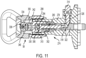
- FIGS. 9-12 illustrate the nozzle assembly 58 of the paint sprayer 14.
- the nozzle assembly 58 includes a valve assembly 274 having a valve body 278 that defines an inlet passageway 282 by which the spray liquid enters the nozzle assembly 58 from the second passageway 158.
- the valve assembly 274 also includes a shut-off valve 286 which includes a plunger 290, a ball 294 supported at a forward end of the plunger 290, and a ball seat 298 in facing relationship with the ball 294.
- the plunger 290 is biased by a spring 302 toward a closed position with the ball 294 seated against the ball seat 298.
- the valve assembly 274 also includes an outlet body 306 defining an outlet of the valve assembly 274.
- the spray liquid flows through the inlet passageway 282 and enters an annular space 310 defined within the outlet body 306.
- the spray liquid within the annular space 310 is pressurized due to the operation of the pump 82 and exerts a force on the forward end of the plunger 290, causing the plunger 290 to retract against the biasing force of the spring 302 and away from the ball seat 298 to an open position.
- the spray liquid then flows through an opening in the ball seat 298 and into the nozzle assembly 58.
- the valve assembly 274 also includes a pressure-release button 314 that is actuable to manually retract the plunger 290 to the open position (e.g., to facilitate cleaning the valve assembly 274 and the nozzle assembly 58).
- the pressure-release button 314 includes a cam portion 318 that engages a follower 322 attached to the plunger 290.
- a spring 326 biases the pressure-release button 314 toward a released position.
- the cam portion 318 exerts a force on the follower 322 that causes the follower 322, with the plunger 290, to retract to the open position of the plunger 290.
- the shut-off valve 286, including the plunger 290, and the spring 302 may be tuned to actuate in response to spray liquids having a fluid viscosity or pressure falling within a desired range, which may include, e.g., various types of paints or stains.
- a desired range which may include, e.g., various types of paints or stains.
- the pressure-release button 314 permits the user to manually open the shut-off valve 286 to facilitate spraying these less viscous spray liquids.
- the pressure-release button 314 also facilitates use of the paint sprayer 14 with a variety of spray liquids (i.e., at pressures lower than what is normally required to open the valve assembly 274), to achieve different spray characteristics, as desired.
- the pressure-release button 314 may be delimited by a detent feature coupled to a user control member, such as a dial.
- the user control member may be actuable to delimit how far the pressure-release button 314 may be depressed, corresponding to different stages of the open position of the shut-off valve 286.
- the different positions of the user control member would cause the detent feature to engage the pressure-release button 314 at different stages, thereby controlling the stage of the open position of the shut-off valve 286.
- Different positions of the pressure-release button 314 can thereby be tuned to different spray liquids (e.g., water, mineral solvent and preservative) to optimize spray characteristics for each spray liquid type.
- spray liquids e.g., water, mineral solvent and preservative
- the nozzle assembly 58 includes a nozzle body 330 having internal threads that removably tighten to external threads on the valve body 278.
- the nozzle assembly 58 also includes a guard 334 attached to the nozzle body 330, a removable and adjustable spray tip 338, and a saddle 342 that seals against the spray tip 338.
- the spray tip 338 is removably and adjustably received into a receptacle 346 defined by the guard 334 and by the saddle 342.
- the spray tip 338 includes a substantially cylindrical barrel 350 that removably and rotatably resides within the receptacle 346, and a handle 354 attached to the barrel 350 and having a shape indicative of an intended flow direction through the spray tip 338.
- the barrel 350 defines a bore 358 extending transversely therethrough relative to a longitudinal dimension of the barrel 350.
- the saddle 342 is supported within the guard 334 and effects a seal against an outer surface of the barrel 350. Spray liquid entering from the valve assembly 274 flows through the saddle 342 and into an upstream end of the bore 358 of the barrel 350, and then exits the spray tip 338 out of a downstream end of the bore 358.
- the spray tip 338 also includes three nozzle inserts positioned within the bore 358.
- the nozzle components include a guide nozzle insert 362, a diverging nozzle insert 366, and a converging nozzle insert 370.
- Spray liquid flowing into the bore 358 first flows through the guide nozzle insert 362, which directs the spray liquid in a stream toward the diverging nozzle insert 366.
- Spray liquid entering the diverging nozzle insert 366 turbulates within a turbulation chamber 374 defined between the diverging and converging nozzle inserts 366, 370.
- the turbulated spray liquid then flows through the converging nozzle insert 370, which defines a nozzle outlet 378.
- Spray liquid exiting the nozzle outlet 378 atomizes in a spray that can be directed toward the workpiece.
- the spray tip 338 can be removed from the receptacle 346, e.g., for cleaning or to be replaced with another spray tip.
- the spray tip 338 can also be rotated 180 degrees within the receptacle 346 so that the three nozzle inserts become arranged in reverse order relative to the order depicted in FIG. 10 (the intended flow direction). With the spray tip 338 rotated 180 degrees, cleaning solution can be directed through the bore 'backwards' (i.e., in a direction opposite the intended flow direction) to facilitate cleaning the nozzle inserts.
- a user first positions the reservoir 86 in the paint sprayer 14 and closes the cover 138. Then, the user couples the hose transfer connector 178 to the sprayer transfer connector 166 and positions the distal end 194 of the transfer hose 22 in the container (e.g., the paint can 38). Then, the user actuates the mode selection switch 238 to place the paint sprayer 14 in the load mode. The user then presses the trigger 250 to actuate the trigger switch 246 and activate the motor 46.
- a spray liquid such as paint
- pressing the trigger 250 in the load mode initiates an automatic loading or automatic filling cycle.
- the automatic filling cycle will run until the full reservoir sensor 222 stops the cycle.
- the user can stop the automatic filling cycle at any time by actuating the trigger 250 a second time. In this way, a user cannot overfill the reservoir 86, which could cause a rupture.
- the user releases the trigger 250 and uncouples the hose transfer connector 178 from the sprayer transfer connector 166.
- the user can then place the hose transfer connector 178 in another container (e.g., the container 26) containing a fluid, such as water or mineral solvent, which helps prevent drying or hardening of the spray liquid (i.e., if the spray liquid is paint).
- a fluid such as water or mineral solvent, which helps prevent drying or hardening of the spray liquid (i.e., if the spray liquid is paint).
- the user then adjusts the mode selection switch 238 to the spray mode (or, in some embodiments, spray mode is automatically initiated upon disconnection of the hose transfer connector 178 from the sprayer transfer connector 166).
- the user then presses the trigger 250 to actuate the trigger switch 246 and activate the motor 46. This causes the pump 82 to run in the forward mode, drawing spray liquid from the reservoir 86 and pumping the spray liquid toward the nozzle assembly 58.
- the spray liquid enters the inlet passageway 282, where pressure builds until it overcomes the biasing force of the shut-off valve 286 causing the shut-off valve 286 to open.
- the shut-off valve 286 opens, pressurized spray liquid flows from the inlet passageway 282 through the shut-off valve 286 and exits through the spray tip 338 in an atomized spray.
- the aforementioned loading and spraying steps are then repeated each time the reservoir 86 is emptied and requires re-filling, or until the painting job is completed.
- the user couples the hose transfer connector 178 to the sprayer transfer connector 166, and positions the distal end 194 of the transfer hose 22 in the container (e.g., the paint can 38). If any spray liquid remains in the reservoir 86, the user may put the paint sprayer in unload mode by moving the mode selection switch 238 to the unload position, and then run the motor 46 by pulling the trigger 250.
- the user places the distal end 194 of the transfer hose in a container (e.g., such as the container 26) holding a cleaning fluid (e.g., water, mineral solvents, or the like).
- a cleaning fluid e.g., water, mineral solvents, or the like.
- the user couples the hose transfer connector 178 to the sprayer transfer connector 166 (if not already coupled).
- the steps described above with regard to the primary operation for loading and spraying the spray liquid are repeated using the cleaning fluid. That is, the cleaning fluid is loaded into the reservoir 86 and then sprayed out the nozzle assembly 58 to clean the components of the paint sprayer 14.
- the user may repeat these loading and spraying steps as many times as needed to perform further cleaning.
- the user may also operate the paint sprayer 14 in the unload mode as described above to more rapidly move the cleaning fluid through the components, which may increase effectiveness of the cleaning.
- a preservative may be pumped through the paint sprayer 14 to coat the internal components (e.g., prior to storing the paint sprayer 14) according to the same steps described above regarding the primary operation.
- the spray liquid can be mixed within a container, such as the paint can 38 or the container 26, by operating the paint sprayer 14.
- a container such as the paint can 38 or the container 26, by operating the paint sprayer 14.
- the user performs the steps of the primary operation described above including connecting the transfer hose 22 to the paint sprayer 14 and loading the reservoir 86 with the spray liquid.
- the user places the paint sprayer 14 in unload mode and operates the paint sprayer 14 to load the spray liquid back into the container from which it was drawn.
- the spray liquid re-entering the container will mix within the container due to the loading and unloading operations.
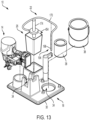
- FIGS. 13 and 14 illustrate all or portions of the painting system 10 in further detail.
- the painting system 10 includes the paint sprayer 14, the base 30, the transfer hose 22, and the container 26.
- the painting system 10 is also operable with the paint can 38, which can be of different sizes and can contain a paint material, stain material, a solvent material, a preservative material, or other spray liquids.
- the base 30 includes a base wall 382, the first support portion 262, a second support portion 386, a third support portion 390, and a tip well 394.
- Each of the first, second, and third support portions 262, 386, 390, and the tip well 394, may be coupled to the base wall 382, or, alternatively, may be integrally formed with the base wall 382.
- the base 30 also includes a hose guide 398 coupled to the base wall 382.
- the hose guide 398 includes an elongated shaft portion 402 extending upward from the base wall 382, and a hook portion 406 located at a distal end of the shaft portion 402.
- the hook portion 406 receives and supports the hose segment 170 at an elevated position relative to the base wall 382, which conveniently facilitates positioning the distal end 194 of the transfer hose 22 in the container (e.g., the paint can 38 or the container 26).
- the first support portion 262 defines a first receptacle 408 that removably receives and supports the paint sprayer 14 in the orientation illustrated in FIGS. 1 and 2 , with the spray tip 338 positioned within the tip well 394 and pointing downward. More specifically, the first support portion 262 includes a plurality of raised posts 410 spaced apart from one another such that the posts 410 extend on either lateral side of the housing 42 of the paint sprayer 14 to stably support the paint sprayer 14. The first support portion 262 engages the paint sprayer 14 beneath its center of gravity (CG), so that the paint sprayer 14 remains stably balanced on the first support portion 262.
- CG center of gravity
- the first support portion 262 may include an additional shelf positioned to support the battery pack 50 when the battery pack 50 is coupled to the paint sprayer 14.
- the shelf may ensure that the paint sprayer 14 does not tip over or otherwise fall off of the first support portion 262 when batteries of different sizes and weights are coupled thereto and affect the CG of the paint sprayer 14.
- the tip well 394 includes a raised annular (or, circular) wall 414 protruding upward from the base wall 382 and defining a recess or well 418 therewithin.
- the well 418 receives the spray tip 338 of the nozzle assembly 58 when the paint sprayer 14 is received into the first receptacle 408 of the first support portion 262.
- the spray tip 338 or guard 334 may contact the base wall 382 in some embodiments. In other embodiments, the spray tip 338 is suspended above the base wall 382 and the paint sprayer 14 is entirely supported by the first support portion 262.
- the tip well 394 captures drips of the spray liquid that may drip from the spray tip 338.
- the tip well 394 may include a disposable liner (not shown).
- the tip well 394 (or, the liner) can be filled with water, mineral solvent, or another material that can help prevent drying or hardening of the spray liquid.
- the first support portion 262 supports the weight of the paint sprayer 14 with the spray tip 338 oriented downward and suspended within the tip well 394. This orientation ensures safety and minimizes spills during loading or unloading of the spray liquid into or out of the reservoir 86 (i.e., when operating the paint sprayer in the load mode or the unload mode). When supported in this way, the user will not have to hold the paint sprayer 14 during these operations. This leaves the user's hands free to perform other steps of the loading and unloading processes.
- the second support portion 386 includes a raised rectangular (or, square or circular or ovular in some cases) wall 422 protruding upward from the base wall 382 and defining a second receptacle 426 for removably receiving the container 26.
- the second support portion 386 in place of the rectangular wall 422, can include a plurality of spaced-apart protrusions that define the second receptacle. The protrusions are intended to prevent horizontal movement of the container 26, or a liner (not shown) for receiving another liquid such as water, mineral solvent, or preservative.
- the third support portion 390 includes an annular (or, circular) recess 430 recessed into the base wall 382 and defined by a cylindrical wall 434 and a bottom wall 438.
- the cylindrical wall 434 and the bottom wall 438 define a third receptacle 442 that receives a paint can 38 of a first size (e.g., one pint).
- the third support portion 390 further includes a plurality of protrusions 446 (three in the illustrated embodiment) which are spaced radially outward from and about a circumference of the cylindrical wall 434.
- the protrusions 446 cooperatively define a fourth receptacle 450 that receives a paint can of a second, larger size (e.g., one quart).
- the protrusions 446 contact the sides of the paint can 38 of the second size to stably hold the paint can 38.
- the protrusions 446 may be movable (i.e., slidable in a radial direction) so as to accommodate paint cans of other sizes (e.g., one gallon).
- the movable protrusions can be slidable, lockable, removable, and/or collapsible into the base wall 382.
- the container 26 can include a lip 454 which can by grasped by the user, and measurement indicia on the sides.
- the container 26 can also include ridges (not shown) disposed vertically on a sidewall of the container 26 and near a corner thereof for supporting the hose transfer coupler 174 ( FIG. 1 ) in an upright position.
- the base 30 can include one or more additional support portions for supporting additional containers, such as a second paint can 38 or a second container 26.
- the paint sprayer 14 includes the tool support sensor 258 operable to detect when the paint sprayer 14 is properly positioned in the first support portion 262 of the base 30.
- the first support portion 262 of the base 30 can include the tool support sensor, rather than the paint sprayer 14.
- the tool support sensor 258 of the base 30 can detect that the paint sprayer 14 is properly supported on the first support portion 262 and communicate a signal to the controller 210 (e.g., via RFID, Bluetooth, WiFi, NFC, a wired communication, or other communication means).
- the controller 210 will disable the spray mode in response to the signal.
- the base 30 can further include a grounding connection 270 positioned on the first support portion 262 so as to contact the grounding connection 266 of the paint sprayer 14.
- a grounding connection 270 positioned on the first support portion 262 so as to contact the grounding connection 266 of the paint sprayer 14.
- Contact between the ground connections 266, 270 facilitates grounding of the paint sprayer to reduce a likelihood of arcing in the paint sprayer 14 when loading or unloading. This improves safety of the painting system 10, particularly when working with combustible fluids.
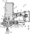
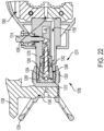
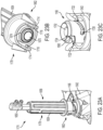
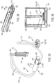
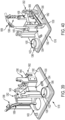
- FIGS. 15-38 illustrate a painting system 1010 that is substantially similar to the painting system 10 described herein and in connection with FIGS. 1-14 .
- the following description will primarily focus on the differences or additional features of the painting system 1010 as compared to the painting system 10.
- Features and elements of the painting system 1010 similar to or corresponding to like features and elements of the painting system 10 will be assigned the same reference numbers plus "1000.”
- the painting system 1010 includes a paint sprayer 1014, a base assembly 1018, and a transfer hose 1022.
- the base assembly 1018 includes a base 1030 with a plurality of receptacles 1034 for removably receiving and storing the paint sprayer 1014, the transfer hose 1022, and a paint can 1038.
- the transfer hose 1022 selectively fluidly couples to the paint sprayer 1014 to facilitate loading or unloading the paint sprayer 1014 with a spray liquid (e.g., paints, stains, or cleaning solutions such as water, solvents, or the like).
- a spray liquid e.g., paints, stains, or cleaning solutions such as water, solvents, or the like.
- the paint sprayer 1014 is a portable, electric paint sprayer 1014 that includes a housing 1042 and an electric motor 1046.
- the paint sprayer 1014 is operable with the battery pack 50 removably coupled to a battery receptacle 1054 located at a bottom end of the housing 1042.
- the motor 1046 includes a stator assembly 1047 and a rotor assembly 1048 that is rotatable with respect to the stator assembly 1047 about an axis.
- the motor 1046 can be a brushless direct current (“BLDC”) motor where the stator assembly is electronically commutated.
- BLDC brushless direct current
- the paint sprayer 1014 also includes a nozzle assembly 1058 coupled to the housing 1042.
- the housing 1042 includes a handle portion 1062 coupled to the battery receptacle 1054, and a main portion 1066 coupled to the nozzle assembly 1058.
- the handle portion 1062 supports a trigger assembly 1070 that is electrically connected to the motor 1046 and operable to selectively activate the motor 1046.
- the housing 1042 can include a pair of clamshell halves 1074 coupled together along a central parting plane and forming both the handle portion 1062 and the main portion 1066.
- the main portion 1066 of the housing 1042 encloses a first internal space 1078 in which the motor 1046 is supported.
- the paint sprayer 1014 also includes a pump 1082 operably coupled to the motor 1046 and positioned within the first internal space 1078 of the main portion 1066.
- the pump 1082 is fluidly connected to the nozzle assembly 1058 and mechanically coupled to the motor 1046.
- the paint sprayer 1014 further includes a reservoir 1086 positioned within the housing 1042 and fluidly connected to the pump 1082.
- the reservoir 1086 can receive, store, and supply the spray liquid. In particular, the reservoir 1086 can receive the spray liquid from the pump 1082, store the spray liquid, and also supply the spray liquid to the pump 1082.
- the pump 1082 includes a first inlet 1090, a second inlet 1094, and an outlet 1096.
- the pump 1082 is operable in both a forward mode and a reverse mode. In the forward mode, the pump 1082 draws in the spray liquid through the first inlet 1090 and expels the spray liquid through the second inlet 1094 or the outlet 1096. Conversely, in the reverse mode, the pump 1082 draws in the spray liquid through the second inlet 1094 and expels the spray liquid through the first inlet 1090.
- the pump 1082 may be operated in the forward mode by operating the motor 1046 in a first, or forward, rotational direction, and may be operated in the reverse mode by operating the motor 1046 in an opposite second, or reverse, rotational direction.
- the pump 1082 is a gear pump.
- the pump 1082 may instead be another type of pump, such as, e.g., a piston pump, a diaphragm pump, a peristaltic pump, or the like.
- the reservoir 1086 is a collapsible reservoir having a collapsible portion 1098 capable of expanding or contracting in response to the reservoir 1086 being loaded or unloaded with the spray liquid.
- the reservoir 1086 defines a variable internal volume 1102 and expands and contracts between full and empty states. When the collapsible portion 1098 expands, the variable internal volume 1102 increases, and when the collapsible portion 1098 contracts, the variable internal volume 1102 decreases.
- the variable internal volume 1102 in the empty state of the reservoir 1086 is ninety percent or less of the variable internal volume 1102 in the filled state.
- the variable internal volume 1102 in the empty state of the reservoir 1086 is fifty percent or less of the variable internal volume 1102 in the filled state.
- the collapsible portion 1098 can be formed as a flexible bag 1098 having flexible walls 1106 formed from, e.g., sheets of multi-ply plastic material that are bonded (e.g., crimped, glued, etc.) on all edges. As the collapsible portion 1098 expands, the flexible walls 1106 unfold away from each other, and as the collapsible portion 1098 contracts, the flexible walls 1106 fold toward one another.
- the reservoir 1086 also includes a rigid coupler 1114 coupled to the collapsible portion 1098.
- the rigid coupler 1114 is fixedly attached to the collapsible portion 1098 and defines an inlet of the reservoir 1086.
- the rigid coupler 1114 is externally threaded.
- the paint sprayer 1014 also includes a reservoir adapter 1116.
- the reservoir adapter 1116 is internally threaded and removably threads onto the rigid coupler 1114 of the reservoir 1086.
- the reservoir adapter 1116 includes a connector plug 1117 that is sized and shaped to removably couple to the paint sprayer 1014, thereby fluidly connecting the pump 1082 with the reservoir 1086.
- the paint sprayer 1014 includes a coupler receptacle 1122 supported within the housing 1042.
- the coupler receptacle 1122 is fluidly connected to the first inlet 1090 of the pump 1082 via a first passageway 1126 ( FIG. 21 ).
- the coupler receptacle 1122 removably fluidly couples to the connector plug 1117 to thereby fluidly connect the reservoir 1086 to the pump 1082.
- the connector plug 1117 carries a gasket 1127 (e.g., an O-ring) which creates a fluid tight seal between the connector plug 1117 and the coupler receptacle 1122.
- the connector plug 1117 also carries a round circlip or wire snap ring 1128 that engages with the coupler receptacle 1122 to secure the removable connection.
- the paint sprayer 1014 can also include an inlet plug 1129 that is externally threaded and can thread onto the reservoir adapter 1116 in place of the reservoir 1086 when the reservoir 1086 is disconnected.
- the reservoir adapter 1116 with the inlet plug 1129 can be installed in the coupler receptacle 1122 to prevent dirt or other debris from entering the coupler receptacle 1122 when the reservoir 1086 is not installed.
- the housing 1042 includes a plug mount protruding into the second internal space 1130 to which the inlet plug 1129 can be selectively mounted and thereby stored when not in use.
- the reservoir 1086 of the paint sprayer 1014 is entirely enclosed within the housing 1042.
- the housing 1042 further defines and encloses a second internal space 1130 which is separated from the first internal space 1078 by a divider wall 1134.
- the reservoir 1086 is located within the second internal space 1130.
- the divider wall 1134 separates the reservoir 1086 from the first internal space 1078 so that leaked or spilled spray liquid emitted from the reservoir 1086 can be contained within the second internal space 1130 and will not interfere with the motor 1046, pump 1082, or other components located within the first internal space 1078.
- the divider wall 1134 may be formed as part of the clamshell halves 1074 or may be formed as a separate component.
- the coupler receptacle 1122 protrudes at least partially through the divider wall 1134 and into the second internal space 1130, which allows the coupler receptacle to access the reservoir 1086 and couple to the reservoir adapter 1116.
- the housing 1042 further includes a reservoir housing member 1138 coupled to the main portion 1066.
- the reservoir housing member 1138 is formed as a door or cover 1138.
- the cover 1138 removably couples to the main portion 1066 and selectively removes to reveal the second internal space 1130 and permit insertion, removal, or replacement of the reservoir 1086.
- the cover 1138 is completely removable from the main portion 1066 and selectively secures to the main portion 1066 via engagement between protrusions 1139 on the reservoir housing member 1138 being tightly received into slots 1140 ( FIG. 18 ) defined in the main portion 1066.
- slots 1140 FIG. 18
- the cover can instead be secured to the main portion by a hinge (e.g., hinge 142) and pivotable about a hinge axis 146 between open and closed positions.
- the cover 1138 can further be secured to the main body portion 1066 in a manner consistent with that described herein with respect to FIG. 5 .
- the second internal space 1130 is located generally above the handle portion 1062 when the paint sprayer 1014 is oriented in an upright or spray orientation.
- the reservoir 1086 is also located above the handle portion 1062 in this orientation of the paint sprayer 1014.
- the handle portion 1062 defines a longitudinal handle axis 1150 that intersects the second internal space 1130 and intersects the reservoir 1086.
- the paint sprayer 1014 further includes a second passageway 1158 extending between and fluidly connecting the outlet 1096 of the pump 1082 with the nozzle assembly 1058.
- the reservoir 1086 is fluidly connected with the nozzle assembly 1058 via the first passageway 1126, the pump 1082, and the outlet 1096.
- a third passageway 1162, or transfer passageway, is fluidly connected to the second inlet 1094 and the second passageway 1158 and extends to a sprayer transfer connector 1166 of the paint sprayer 1014.
- the sprayer transfer connector 1166 can selectively and removably couple to the transfer hose 1022 ( FIG. 15 ), which can fluidly couple the sprayer transfer connector 1166 to an external source of the spray liquid such as the paint can 1038.
- the pump 1082 may be operated in the reverse mode to draw spray liquid from the paint can 1038 into the reservoir 1086. Specifically, the spray liquid moves from the paint can 1038 to the reservoir 1086 via the transfer hose 1022, the sprayer transfer connector 1166, the third passageway 1162, the pump 1082 via the second inlet 1094 to the first inlet 1090, the first passageway 1126, and the coupler receptacle 1122. Alternatively, the pump 1082 may be operated in the forward mode to empty the reservoir 1086 and expel the spray liquid out of the paint sprayer 1014 via the sprayer transfer connector 1166 along a similar pathway. The spray liquid exiting via the sprayer transfer connector 1166 can move through the transfer hose 1022 and flow back into the paint can 1038, or to another external container.
- the nozzle assembly 1058 includes a valve assembly 1274 having a valve body 1278 that defines the second passageway 1158 by which the spray liquid enters the nozzle assembly 1058 from the outlet 1096.
- the valve assembly 1274 also includes a shut-off valve 1286 which includes a plunger 1290, a ball 1294 supported at a forward end of the plunger 1290, and a ball seat 1298 in facing relationship with the ball 1294.
- the plunger 1290 is biased by a spring 1302 toward a closed position with the ball 1294 seated against the ball seat 1298.
- the spray liquid flows through the second passageway 1158 and enters an annular space 1310 defined within the ball seat 1298 and the valve body 1278.
- the spray liquid within the annular space 1310 is pressurized due to the operation of the pump 1082 and exerts a force on the forward end of the plunger 1290, causing the plunger 1290 to retract against the biasing force of the spring 1302 and away from the ball seat 1298 to an open position.
- the spray liquid then flows through an opening in the ball seat 1298 and into the nozzle assembly 1058.
- valve assembly 1274 also includes a pressure-release button 1314 that is actuable to manually retract the plunger 1290 to the open position (e.g., to facilitate cleaning the valve assembly 1274 and the nozzle assembly 1058).
- the pressure-release button 1314 is substantially the same in both structure and function as the pressure-release button 314 described herein.
- the nozzle assembly 1058 includes a nozzle body 1330 having internal threads that removably tighten to external threads on the valve body 1278.
- the nozzle body 1330 defines a guard portion 1334 and a cylindrical receptacle 1346 that receives a removable and adjustable spray tip 1338.
- the spray tip 1338 is substantially similar to the spray tip 338 described herein. Like the spray tip 338, the spray tip 1338 can be removed from the receptacle 1346, e.g., for cleaning or to be replaced with another spray tip. The spray tip 1338 can also be rotated 180 degrees within the receptacle 1346 for cleaning, as described herein with respect to the spray tip 338.
- the transfer hose 1022 includes a primary hose segment 1170 and a hose transfer coupler 1174 coupled to the primary hose segment 1170.
- the hose transfer coupler 1174 includes a hose transfer connector 1178 fluidly connected to a manifold 1650.
- the hose transfer connector 1178 selectively connects to the sprayer transfer connector 1166 to fluidly connect the primary hose segment 1170 to the paint sprayer 1014.
- FIGS. 23A-25 illustrate the hose transfer connector 1178 and the sprayer transfer connector 1166.
- the hose transfer connector 1178 includes a handle 1654 defining a hollow interior, a grip portion 1658 and a connector portion 1662.
- a hose valve assembly 1666 is positioned within the handle 1654 and fluidly coupled to the primary hose segment 1170.
- the hose transfer connector 1178 also includes a hose valve stem 1670 that is axially immovably secured within the handle 1654.
- the hose valve stem 1670 internally defines a hose stem passageway 1672 which is fluidly connected to the manifold 1650.
- the manifold 1650 fluidly connects the hose valve stem 1670 to the primary hose segment 1170.
- the hose transfer connector 1178 also includes an annular hose valve body 1674 disposed concentrically around the hose valve stem 1670 and within the handle 1654.
- the hose valve body 1674 defines an orifice 1678 that is normally closed by a hose stem head 1682 of the hose valve stem 1670.
- the hose valve body 1674 is slidably disposed about the hose valve stem 1670 and biased by a hose valve spring 1686 toward a forward, closed position ( FIG. 24 ) at which the hose stem head 1682 closes the orifice 1678.
- the sprayer transfer connector 1166 includes a connector body 1690 and a sprayer valve assembly 1692.
- the connector body 1690 is annular and defines a hollow interior and is secured to the housing 1042.
- the connector body 1690 is also fluidly connected to the third passageway 1162 and to the second inlet 1094 of the pump 1082.
- the connector body 1690 defines an orifice 1698.
- the sprayer valve assembly 1692 includes a sprayer valve stem 1694 having a sprayer stem head 1702 that normally closes the orifice 1698 of the sprayer valve stem 1694.
- the sprayer valve stem 1694 is slidably disposed within the connector body 1690 and is biased by a sprayer valve spring 1706 toward a forward, closed position ( FIG. 24 ) at which the sprayer stem head 1702 closes the orifice 1698.
- the connector body 1690 presses against the hose valve body 1674, causing the hose valve body 1674 to retract to an open position at which the hose stem head 1682 no longer blocks the orifice 1678.
- the spray liquid is then permitted to flow through the orifice 1678 into or out from the hose valve stem 1670.
- the hose stem head 1682 presses against the sprayer stem head 1702, causing the sprayer valve stem 1694 to retract to an open position at which the sprayer stem head 1702 no longer blocks the orifice 1698.
- the spray liquid is then permitted to flow through the orifice 1698 into or out from the connector body 1690.
- a flow pathway 1710 extends from the hose stem passageway 1672, through the orifice 1678 of the hose valve body 1674, through the orifice 1698, and through the connector body 1690 (passing through openings in the sprayer valve stem 1694), and into the third passageway 1162.
- the spray liquid can flow along the flow pathway 1710 in either direction.
- the connector portion 1662 of the handle 1654 includes two mounting tabs 1714 positioned about 180 degrees apart from one another and protruding in both the axial and radial directions.
- Each mounting tab 1714 defines a lug 1718 which protrudes radially inward from an inner surface of the mounting tab 1714.
- the connector body 1690 defines two helical grooves or channels 1722 in its outer circumferential surface.
- Each channel 1722 includes an opening 1724 at its axially distal end and includes an axially extending notch 1726 at its opposite, proximal end.
- the paint sprayer 1014 also includes a control system 1206 for controlling various operations of the paint sprayer 1014.
- the control system 1206 includes an electronic controller 1210 supported within the main portion 1066 of the housing 1042.
- the controller 1210 controls the operation of the paint sprayer 1014 according to three operation modes including a load mode, an unload mode, and a spray mode.
- the paint sprayer 1014 is operable in the load mode and in the unload mode when the hose transfer connector 1178 is coupled to the sprayer transfer connector 1166.
- the paint sprayer 1014 is operable in the spray mode when the hose transfer connector 1178 is disconnected from the sprayer transfer connector 1166.
- the hose transfer connector 1178 is connected to the sprayer transfer connector 1166 and the valve assemblies 1666, 1692 of the connectors 1166, 1178 are open.
- the motor 1046 operates in the reverse rotational direction and the pump 1082 operates in the reverse mode to draw spray liquid in through the sprayer transfer connector 1166 (i.e., via the transfer hose 1022 inserted into the external container) and direct the spray liquid into the reservoir 1086 to fill the reservoir 1086.
- the motor 1046 When the paint sprayer 1014 is operated in the unload mode, the motor 1046 operates in the forward rotational direction and the pump 1082 operates in the forward mode to draw the spray liquid out of the reservoir 1086 and expel the spray liquid out through the sprayer transfer connector 1166 (i.e., and into the external container via the transfer hose 1022).
- the sprayer transfer connector 1166 In the spray mode, the sprayer transfer connector 1166 is disconnected from the hose transfer connector 1178 and the sprayer valve assembly 1692 within the sprayer transfer connector 1166 is closed.
- the motor 1046 When the paint sprayer 1014 is operated in the spray mode, the motor 1046 operates in the forward rotational direction and the pump 1082 operates in the forward mode to draw the spray liquid out of the reservoir 1086 and direct the spray liquid through the nozzle assembly 1058 to perform a paint spraying operation or a cleaning operation.
- the paint sprayer 1014 includes a barbed anchor 1728 located toward a rear end 1730 of the second internal space 1130 on one lateral side thereof.
- the control system 1206 also includes a reservoir installed sensor 1754 in electrical communication with the controller 210 and operable to detect when the reservoir 1086 is installed.
- the reservoir installed sensor 1754 is also located toward the rear end 1730 of the second internal space 1130 on another lateral side opposite from the barbed anchor 1728.
- the reservoir installed sensor 1754 includes a barbed plunger 1756 that is retractable from an extended position to a retracted position, and spring-biased toward the extended position.
- the barbed anchor 1728 and the barbed plunger 1756 are received into respective apertures (not shown) defined in rear flap portions of the reservoir 1086 and held therein by their respective barbs.
- the 1086 is therefore anchored within the second internal space 1130 at three points, namely, the rigid coupler 1114, the barbed anchor 1728, and the barbed plunger 1756 of the reservoir installed sensor 1754.
- the barbed plunger 1756 is coupled to the flap of the reservoir 1086, the barbed plunger 1756 is pulled outward to the extended position against the bias of the spring.
- the barbed plunger 1756 actuates a switch 1738 to signal the controller 1210 that the reservoir 1086 is installed.
- the switch 1738 signals the controller that the reservoir 1086 is removed.
- the control system 1206 also includes an empty reservoir sensor 1226 in electrical communication with the controller 1210 and operable to detect when the reservoir 1086 is empty.
- the empty reservoir sensor 1226 detects a low pressure within the first passageway 1126 which is indicative of the reservoir 1086 being empty when the pump 1082 is operating in the forward mode corresponding to the spray mode or the unload mode.
- the empty reservoir sensor 1226 includes an optical sensor 1232 and one or more permanent magnets 1234.
- the empty reservoir sensor 1226 also includes a diaphragm 1742 coupled to a plunger 1746. The diaphragm 1742 fluidly communicates with the first passageway 1126.
- the empty reservoir sensor 1226 further includes a biasing member 1750, such as a spring, which biases the diaphragm 1742 away from the first passageway 1126.
- the diaphragm 1742 In response to a low pressure of the spray liquid within the first passageway 1126, the diaphragm 1742 stretches toward the first passageway 1126, causing the plunger 1746 to move. The plunger 1746 moves relative to the optical sensor 1232, causing the optical sensor 1232 to send a signal to the controller 1210 indicative that the reservoir 1086 is empty.
- a low pressure develops within the first passageway 1126.
- the vacuum sensor 1226 detects the low pressure within the first passageway 1126 and in response, communicates the signal to the controller 1210 indicating that the reservoir 1086 is empty.
- the controller 1210 can disable operation of the motor 1046 to prevent the pump 1082 from running dry.
- the signal from the empty reservoir sensor 1226 may only be sent to the controller 1210 when the paint sprayer 1014 is in the unload mode or the spray mode.
- the controller 1210 in response to receiving the signal indicating that the reservoir 1086 is empty, can actuate an indicator, such as an LED (not shown), to inform a user that the reservoir is empty. The controller 1210 can turn off such indication when it is no longer receiving the signal.
- the control system 1206 also includes a full reservoir sensor 1222.
- the full reservoir sensor 1222 detects when the reservoir 1086 is full.
- the full reservoir sensor 1222 includes a switch 1758, a plunger 1762, and a spring 1766.
- the spring 1766 biases the plunger 1762 toward the second internal space 1130 such that a portion of the plunger 1762 protrudes into the second internal space 1130 when the reservoir 1086 is not full.
- the collapsible portion 1098 of the reservoir 1086 when full presses against the plunger 1762 such that the plunger 1762 retracts.
- the plunger 1762 engages the switch 1758, causing the switch 1758 to communicate a signal to the controller 1210 indicating that the reservoir 1086 is full.
- the control system 1206 also includes a transfer connection sensor 1242 that detects when the hose transfer connector 1178 is connected to the sprayer transfer connector 1166.
- the transfer connection sensor 1242 includes a collar 1770 positioned concentrically about the connector body 1690 and rotatable relative to the connector body 1690 between a disengaged, or unactuated, position (not shown), and an engaged, or actuated, position ( FIGS. 29 and 30 ).
- the transfer connection sensor 1242 also includes a biasing member or spring 1774 which biases the collar 1770 toward the unactuated position.
- the transfer connection sensor 1242 further includes a switch 1778 electrically connected to the controller 1210.
- the collar 1770 includes a first leg or tab 1782.
- the collar 1770 also includes a second leg or tab 1786 that is located proximate the switch 1778.
- the switch 1778 As the hose transfer connector 1178 is coupled to the sprayer transfer connector 1166, the mounting tab 1714 engages and pushes the tab 1782, causing the collar 1770 to rotate from the unactuated position to the actuated position.
- the tab 1786 engages and actuates the switch 1778.
- the controller 1210 may disable the spray mode and may limit the speed of the motor 1046. In the absence of the signal, the controller 1210 may disable the load and/or unload modes.
- the control system 1206 also includes a variable speed selector 1254.
- the selector 1254 is actuated by a dial and is operable to adjust a speed of the motor 1046, e.g., by varying the duty cycle of the motor 1046 via, e.g., pulse width modulation. By varying the speed of the motor 1046, a flow rate and pressure of the spray liquid discharged from the pump 1082 can be varied.
- the selector 1254 may only be operable in the spray mode, to vary a flow rate, pressure, and/or spray pattern of the spray liquid discharged from the nozzle assembly 1058. In the load mode and the unload mode, however, the speed of the motor 1046 may be limited and may not be varied by adjusting the selector 254. This can be done for reasons of safety, i.e., to prevent spillage, splashing, or splatter while unloading the spray liquid from the reservoir 1086, or to prevent damage to the reservoir 1086 during loading.
- the paint sprayer 1014 also includes an indicator panel 1802 operable to indicate information about the paint sprayer 1014 to the user.
- the indicator panel 1802 may indicate such information as, e.g., a setting of the variable speed selector 1254.
- the control system 1206 further includes a trigger switch 1246 operable to communicate an ON or OFF signal to the controller 1210. In response to the ON signal, the controller 1210 may activate the motor 1046.
- the trigger switch 1246 can be incorporated into the trigger assembly 1070 and may be actuated by a trigger 1250 of the trigger assembly 1070.
- FIGS. 32-39 illustrate all or portions of the painting system 1010 in further detail.
- the painting system 1010 includes the paint sprayer 1014, the base assembly 1018, the transfer hose 1022, a container 1026, and a removable mount 1806 for the hose transfer connector 1178.
- the painting system 1010 is also operable with the paint can 1038, which can be of different sizes and can contain a paint material, stain material, a solvent material, a preservative material, or other spray liquids.
- FIGS. 33-35 illustrate all or portions of the transfer hose 1022 in greater detail.
- the transfer hose 1022 includes a weight member 1198 located at a distal end 1194 of the primary hose segment 1170 opposite from the hose transfer coupler 1174.
- the weight member 1198 is configured to be positioned in a container containing the spray liquid, such as the paint can 1038.
- the weight member 1198 may be formed from a material having a greater density than that of the spray liquid, so that the weight member 1198 will tend to sink toward the bottom of the container and remain submerged in the spray liquid.
- the transfer hose 1022 also includes a priming mechanism 1826 connected to the manifold 1650 of the hose transfer coupler 1174.
- the priming mechanism 1826 includes a syringe assembly 1830 and a priming hose segment 1834 fluidly connecting the syringe assembly 1830 to the manifold 1650.
- the syringe assembly 1830 includes a barrel 1838 fluidly coupled to the priming hose segment 1834, and a plunger 1842 disposed within the barrel 1838.
- the barrel 1838 and the plunger 1842 define a priming chamber 1840 having a variable volume which changes as the plunger 1842 moves into or out of the barrel 1838.
- the spray liquid can be drawn into the priming chamber 1840 and subsequently forced out of the priming chamber 1840 toward the pump 1082 of the paint sprayer 1014 to prime the pump 1082, as will be explained herein.
- the syringe assembly 1830 also includes a syringe housing 1846 that receives and holds the barrel 1838.
- the syringe housing 1846 also defines a hose channel 1850 that receives and holds a portion of the primary hose segment 1170.
- the syringe housing 1846 also includes a shaft segment or rod 1854 located proximate the hose channel 1850.
- the rod 1854 provides a surface for pinching the primary hose segment 1170 to selectively prevent the spray liquid from flowing through the primary hose segment 1170 during a priming operation.
- the primary hose segment 1170 may be selectively blocked by another means, such as an inline shut-off valve (not shown).
- FIG. 36 illustrates a method 2000 of priming the paint sprayer 1014 via transfer hose 1022 with the priming mechanism 1826.
- the paint sprayer 1014 is placed in the load mode via the mode selection switch 1238.
- the hose transfer connector 1178 is connected to the sprayer transfer connector 1166.
- the distal end 1194 of the primary hose segment 1170 is also submerged in a container containing spray liquid (e.g., the paint can 1038).
- spray liquid is drawn into the priming chamber 1840 of the syringe assembly 1830. This is done by pulling the plunger 1842 out from the barrel 1838, which suctions the spray liquid into the barrel 1838.
- the spray liquid flows from the container into the primary hose segment 1170, from the primary hose segment 1170 to the manifold 1650, from the manifold 1650 to the priming hose segment 1834, and from the priming hose segment 1834 into the barrel 1838.
- steps 2008 and 2012 can be performed in reverse order.
- the spray liquid can first be drawn into the priming chamber 1840 (with the distal end 1194 submerged in the container) with the hose transfer connector 1178 not yet connected to the sprayer transfer connector 1166, and then the hose transfer connector 1178 can subsequently be connected to the sprayer transfer connector 1166.
- the primary hose segment 1170 is then blocked to prevent the spray liquid from flowing therethrough.
- the primary hose segment 1170 can be blocked by pinching the primary hose segment 1170.
- the primary hose segment 1170 can be wrapped backward tightly around the rod 1854 of the syringe housing 1846 to pinch the primary hose segment 1170.
- the spray liquid is then forced out of the priming chamber 1840 and into the pump 1082 while the primary hose segment 1170 is maintained in a blocked or pinched state. Specifically, the plunger 1842 is pushed back into the barrel 1838, which forces the spray liquid out of the priming chamber 1840 and into the priming hose segment 1834.
- the spray liquid flows from the priming hose segment 1834 into the manifold 1650, and because the primary hose segment 1170 is being held blocked, the spray liquid flows from the manifold 1650 into the hose transfer connector 1178, the sprayer transfer connector 1166, and finally, into the pump 1082 via the second inlet 1094 ( FIG. 21 ).
- the pump 1082 is then primed and the primary hose segment 1170 can be unblocked (step 2024). Any remaining excess spray liquid within the priming chamber 1840 can be forced out, e.g., by pressing the plunger 1842 the rest of the way into the barrel 1838. Remaining spray liquid exiting the priming chamber 1840 will flow back through the primary hose segment 1170 once it has been unblocked, and back into the container.
- the reservoir 1086 can then be loaded by pressing the trigger assembly 1070 to operate the primed pump 1082.
- FIGS. 37 and 38 illustrate the painting system 1010 with the paint sprayer 1014, the transfer hose 1022, the paint can 1038, the container 1026, and the mount 1806 supported on the base assembly 1018.
- the distal end 1194 including the filter assembly 1202 is submerged in the paint can 1038 and the hose transfer connector 1178 is connected to the sprayer transfer connector 1166.
- the painting system 1010 is thus arranged to operate in the load mode to fill the reservoir 1086, the unload mode to empty the reservoir 1086, or to perform the priming method 2000 to prime the pump 1082.
- the base 1030 includes a base wall 1382, a first support portion 1262, a second support portion 1386, a third support portion 1390, a fourth support portion 1450, and a container receptacle 1394.
- Each of the first, second, third, and fourth support portions 1262, 1386, 1390, 1450, and the container receptacle 1394 may be coupled to the base wall 1382, or, alternatively, may be integrally formed with the base wall 1382.
- the base 1030 also includes a hose guide mount 1398 coupled to the base wall 1382 that may assist the user to holding the hose in the proper position and adjusting the vertical position of the hose.
- the base assembly 1018 further includes a hose guide 1858 that removably couples to the hose guide mount 1398.
- the hose guide 1858 is rigid and elongated and defines a hose receiving channel which receives the distal end 1194 of the primary hose segment 1170. When the paint can 1038 or other container is received in the fourth support portion 1450, the hose guide 1858 conveniently holds the distal end 1194 in the container.
- the first support portion 1262 defines a first receptacle 1408 that removably receives and supports the paint sprayer 1014 in the orientation illustrated in FIGS. 37 and 38 , with the spray tip 1338 positioned within the container 1026 held in the container receptacle 1394, with the spray tip 1338 pointing downward.
- the container 1026 thus captures drips of the spray liquid that may drip from the spray tip 1338.
- the container 1026 can be filled with water, mineral solvent, or another material that can help prevent drying or hardening of the spray liquid in the paint sprayer 1014 (e.g., in the spray tip 1338).
- the first support portion 1262 supports the weight of the paint sprayer 1014 with the spray tip 1338 oriented downward and suspended within the container 1026. This orientation ensures safety and minimizes spills during loading or unloading of the spray liquid into or out of the reservoir 1086 (i.e., when operating the paint sprayer in the load mode or the unload mode). When supported in this way, the user will not have to hold the paint sprayer 1014 during these operations. This leaves the user's hands free to perform other steps of the loading and unloading processes.
- the second support portion 1386 includes a raised circular wall 1422 protruding upward from the base wall 1382 and defining a second receptacle 1426 for removably receiving the mount 1806.
- the mount 1806 receives and holds the hose transfer coupler 1174 when it is not connected to the paint sprayer 1014. Any spray liquid which spills from the hose transfer coupler 1174 is captured by the mount 1806, and the mount 1806 can be removed from the second receptacle 1426 for easy cleaning.
- the third support portion 1390 provides a mounting surface to which a priming stand 1862 is mounted.
- the priming stand 1862 defines a priming receptacle 1866 which selectively receives and holds the syringe assembly 1830.
- the priming stand 1862 makes it easier for the user to actuate the plunger 1842 with one hand and pinch the primary hose segment 1170 with the other hand during the pump priming process.
- the paint sprayer 1014 can include a tool support sensor (not shown) operable to detect when the paint sprayer 1014 is properly positioned in the first support portion 1262 of the base 1030.
- the first support portion 1262 of the base 1030 can include the tool support sensor, rather than the paint sprayer 1014.
- the tool support sensor of the base 1030 can detect that the paint sprayer 1014 is properly supported on the first support portion 1262 and communicate a signal to the controller 1210 (e.g., via RFID, Bluetooth, WiFi, NFC, a wired communication, or other communication means).
- the controller 1210 will disable the spray mode in response to the signal.
- the base 1030 can further include a grounding connection (not shown) positioned on the first support portion 1262 so as to contact the grounding connection (not shown) of the paint sprayer 1014.
- a grounding connection (not shown) positioned on the first support portion 1262 so as to contact the grounding connection (not shown) of the paint sprayer 1014.
- Contact between the ground connections facilitates grounding of the paint sprayer 1014 to reduce a likelihood of arcing in the paint sprayer 1014 when loading or unloading. This improves safety of the painting system 1010, particularly when working with combustible fluids.
- operation of the painting system 1010 and the paint sprayer 1014 including primary operation, cleaning operation, and mixing operation, is substantially the same as that described herein for the painting system 10 and the paint sprayer 14.
- a paint sprayer comprising: a housing enclosing an internal space; a nozzle assembly coupled to the housing; a pump assembly fluidly coupled to the nozzle assembly and positioned within a first region of the internal space; and a reservoir fluidly coupled to the pump assembly and configured to hold a spray liquid, the reservoir being positioned within a second region of the internal space.
- the housing further comprises a cover member coupled to the first and second clamshell members, and wherein the cover member partially defines the second region of the internal space.
- a paint sprayer comprising: a housing; a nozzle assembly coupled to the housing; a pump assembly positioned within the housing and fluidly coupled to the nozzle assembly; and a collapsible reservoir fluidly coupled to the pump assembly and configured to hold a spray liquid, the collapsible reservoir including a flexible sidewall and defining a variable internal volume; wherein the collapsible reservoir is movable between a filled state and a partially emptied state, wherein the collapsible reservoir defines a first internal volume in response to being in the filled state and defines a second internal volume in response to being in the partially emptied state, and wherein the second internal volume is less than fifty percent of the first internal volume.
- the housing includes a first clamshell member, a second clamshell member, and a cover member, and wherein the collapsible reservoir is enclosed within an internal space bounded by the first clamshell member, the second clamshell member, and the cover member.
- a paint sprayer comprising: a housing; a nozzle assembly coupled to the housing; a pump assembly positioned within the housing and fluidly coupled to the nozzle assembly; and a collapsible reservoir fluidly coupled to the pump assembly and configured to hold a spray liquid, the collapsible reservoir including a flexible bag and a rigid coupler affixed to the flexible bag.
- Clause 18 The paint sprayer of any of the preceding clauses, wherein the collapsible reservoir is movable between a filled state and a partially emptied state, wherein the collapsible reservoir defines a first internal volume in response to being in the filled state and defines a second internal volume in response to being in the partially emptied state, and wherein the second internal volume is less than ninety percent of the first internal volume.
- the housing includes a first clamshell member, a second clamshell member, and a cover member, and wherein the collapsible reservoir is enclosed within an internal space bounded by the first clamshell member, the second clamshell member, and the cover member.
- a paint sprayer comprising: a housing; a nozzle assembly coupled to the housing; a pump assembly positioned within the housing and fluidly coupled to the nozzle assembly; a reservoir fluidly coupled to the pump assembly and configured to hold a spray liquid; and a transfer coupler fluidly coupled to the pump assembly and configured to selectively connect to an external source of the spray liquid; wherein the pump assembly is operable in a first mode to draw the spray liquid from the external source via the transfer coupler and fill the reservoir.
- valve assembly is configured to open in response to a fluid pressure developed by the pump assembly exceeding a threshold pressure.
- a paint sprayer comprising: a housing; a pump assembly positioned within the housing; and a nozzle assembly fluidly coupled to the pump assembly, the nozzle assembly including a spray tip defining an outlet orifice, a valve assembly positioned upstream from the outlet orifice and downstream from the pump assembly and biased toward a closed position, and an override actuator coupled to the valve assembly; wherein the valve assembly is configured to open in response to a fluid pressure developed by the pump assembly exceeding a threshold pressure; and wherein the override actuator is operable to open the valve assembly irrespective of the fluid pressure.
- valve assembly includes a plunger, a valve seat, and a biasing member configured to bias the plunger toward the valve seat.
- a paint spray system comprising: a paint sprayer configured to spray a spray liquid, the paint sprayer including a pump assembly, a spray tip, and a sprayer transfer coupler fluidly coupled to the pump assembly; a transfer hose including a hose segment and a hose transfer coupler, the hose segment having a first end coupled to the hose transfer coupler and a second end configured to fluidly communicate with a source of the spray liquid, the hose transfer coupler being configured to selectively and removably couple to the sprayer transfer coupler to establish a fluid connection between the pump assembly and the hose segment; and a base including a base wall and a first support portion coupled to the base wall and defining a first receptacle configured to removably receive the paint sprayer.
- a method of priming a paint sprayer of a paint spray system including a transfer hose and a container containing a spray liquid, the transfer hose having a primary hose segment, a hose transfer connector, and a priming mechanism having a priming chamber, the method comprising: connecting the hose transfer connector to the paint sprayer; drawing the spray liquid from the container into the priming chamber of the priming mechanism; and forcing the spray liquid out of the priming chamber and into the paint sprayer.
- Clause 42 The method of any of the preceding clauses, further comprising setting the paint sprayer in a load mode.
- Clause 43 The method of any of the preceding clauses, further comprising blocking the primary hose segment of the transfer hose.
- Clause 44 The method of any of the preceding clauses, further comprising placing an end of the primary hose segment in the container.
Landscapes
- Engineering & Computer Science (AREA)
- General Engineering & Computer Science (AREA)
- Mechanical Engineering (AREA)
- Chemical & Material Sciences (AREA)
- Analytical Chemistry (AREA)
- Nozzles (AREA)
Abstract
Description
- This application claims priority to
U.S. Provisional Patent Application No. 63/590,908, filed October 17, 2023 - The present disclosure relates to painting systems, and more specifically to portable electric paint sprayers.
- Portable electric paint sprayers, sometimes referred to as airless paint sprayers, can finely atomize liquid paint without utilizing a source of compressed air. Airless paint sprayers pressurize liquid paint or other spray liquids (e.g., stain, varnish, or the like) and discharge the paint through small shaped orifices.
- The present disclosure provides, in one aspect, a paint sprayer including: a housing enclosing an internal space; a nozzle assembly coupled to the housing; a pump assembly fluidly coupled to the nozzle assembly and positioned within a first region of the internal space; and a reservoir fluidly coupled to the pump assembly and configured to hold a spray liquid, the reservoir being positioned within a second region of the internal space.
- The present disclosure provides, in another aspect, a paint sprayer including: a housing; a nozzle assembly coupled to the housing; a pump assembly positioned within the housing and fluidly coupled to the nozzle assembly; and a collapsible reservoir fluidly coupled to the pump assembly and configured to hold a spray liquid, the collapsible reservoir including a flexible sidewall and defining a variable internal volume.
- The present disclosure provides, in another aspect, a paint sprayer including: a housing; a nozzle assembly coupled to the housing; a pump assembly positioned within the housing and fluidly coupled to the nozzle assembly; and a collapsible reservoir fluidly coupled to the pump assembly and configured to hold a spray liquid, the collapsible reservoir including a flexible bag and a rigid coupler affixed to the flexible bag.
- The present disclosure provides, in another aspect, a paint sprayer including: a housing; a nozzle assembly coupled to the housing; a pump assembly positioned within the housing and fluidly coupled to the nozzle assembly; a reservoir fluidly coupled to the pump assembly and configured to hold a spray liquid; and a transfer coupler fluidly coupled to the pump assembly and configured to selectively connect to an external source of the spray liquid; wherein the pump assembly is operable in a first mode to draw the spray liquid from the external source via the transfer coupler and fill the reservoir.
- The present disclosure provides, in another aspect, a paint sprayer including: a housing; a pump assembly positioned within the housing; and a nozzle assembly fluidly coupled to the pump assembly, the nozzle assembly including a spray tip defining an outlet orifice, a valve assembly positioned upstream from the outlet orifice and downstream from the pump assembly and biased toward a closed position, and an override actuator coupled to the valve assembly; wherein the valve assembly is configured to open in response to a fluid pressure developed by the pump assembly exceeding a threshold pressure; and wherein the override actuator is operable to open the valve assembly irrespective of the fluid pressure.
- The present disclosure provides, in another aspect, a paint spray system including: a paint sprayer configured to spray a spray liquid, the paint sprayer including a pump assembly, a spray tip, and a sprayer transfer coupler fluidly coupled to the pump assembly; a transfer hose including a hose segment and a hose transfer coupler, the hose segment having a first end coupled to the hose transfer coupler and a second end configured to fluidly communicate with a source of the spray liquid, the hose transfer coupler being configured to selectively and removably couple to the sprayer transfer coupler to establish a fluid connection between the pump assembly and the hose segment; and a base including a base wall and a first support portion coupled to the base wall and defining a first receptacle configured to removably receive the paint sprayer.
- The present disclosure provides, in another aspect, a method of priming a paint sprayer of a paint spray system, the paint spray system including a transfer hose and a container containing a spray liquid, the transfer hose having a primary hose segment, a hose transfer connector, and a priming mechanism having a priming chamber, the method including: connecting the hose transfer connector to the paint sprayer; drawing the spray liquid from the container into the priming chamber of the priming mechanism; and forcing the spray liquid out of the priming chamber and into the paint sprayer
- Other aspects of the disclosure will become apparent by consideration of the detailed description and accompanying drawings.
-
-
FIG. 1 is a perspective view illustrating a painting system according to an embodiment of the disclosure. -
FIG. 2 is another perspective view illustrating the painting system ofFIG. 1 . -
FIG. 3 is a perspective view illustrating portions of a transfer hose of the painting system ofFIG. 1 . -
FIG. 4 is a perspective view illustrating a paint sprayer of the painting system ofFIG. 1 . -
FIG. 5 is a cross-sectional view of the paint sprayer ofFIG. 4 , taken along line 5-5 ofFIG. 4 . -
FIG. 6 is a perspective view illustrating a reservoir of the paint sprayer ofFIG. 4 . -
FIG. 7 is a schematic view illustrating a control system of the paint sprayer ofFIG. 4 . -
FIG. 8 is a schematic view illustrating a control logic for an electronic controller of the control system ofFIG. 7 . -
FIG. 9 is a perspective view illustrating a nozzle assembly of the paint sprayer ofFIG. 4 . -
FIG. 10 is cross-sectional view illustrating the nozzle assembly ofFIG. 9 , taken along line 10-10 ofFIG. 9 . -
FIG. 11 is cross-sectional view illustrating portions of the nozzle assembly ofFIG. 9 , taken along line 11-11 ofFIG. 9 . -
FIG. 12 is a cross-sectional view illustrating portions of the nozzle assembly ofFIG. 9 , taken along line 10-10 ofFIG. 9 . -
FIG. 13 is a partially exploded perspective view illustrating the painting system ofFIG. 1 . -
FIG. 14 is a perspective view illustrating a base of the painting system ofFIG. 1 . -
FIGS. 15 and 16 are perspective views illustrating a painting system according to another embodiment of the disclosure. -
FIG. 17 is a perspective view illustrating a paint sprayer of the painting system ofFIG. 15 . -
FIG. 18 is a partially exploded perspective view illustrating the paint sprayer ofFIG. 17 . -
FIG. 19 is a cross-sectional view of the paint sprayer ofFIG. 17 , taken along line 19-19 ofFIG. 17 . -
FIG. 20 is a partially exploded perspective view of a reservoir assembly of the paint sprayer ofFIG. 17 . -
FIG. 21 is a detailed cross-sectional view showing portions of the paint sprayer ofFIG. 17 , taken along line 19-19 ofFIG. 17 . -
FIG. 22 is a detailed cross-sectional view showing portions of the paint sprayer ofFIG. 17 , taken along line 22-22 ofFIG. 17 . -
FIG. 23A is a partial perspective view showing a hose transfer coupler of the painting system ofFIG. 15 connected to the paint sprayer ofFIG. 17 . -
FIG. 23B is a partial perspective view showing the hose transfer coupler ofFIG. 23 A . -
FIG. 23C is a partial perspective view showing a sprayer transfer connector of the paint sprayer ofFIG. 17 . -
FIG. 24 is a cross sectional view showing the hose transfer coupler ofFIG. 23A disconnected from the paint sprayer ofFIG. 17 , taken along line 19-19 ofFIG. 17 . -
FIG. 25 is a cross sectional view showing the hose transfer coupler ofFIG. 23A connected to the paint sprayer ofFIG. 17 , taken along line 19-19 ofFIG. 17 . -
FIG. 26 is a partial plan view of the paint sprayer ofFIG. 17 with portions removed. -
FIG. 27 is a detailed cross-sectional view showing portions of the paint sprayer ofFIG. 17 , taken along line 19-19 ofFIG. 17 -
FIG. 28 is a detailed cross-sectional view showing portions of the paint sprayer ofFIG. 17 , taken along line 19-19 ofFIG. 17 . -
FIG. 29 is a partial perspective view showing the hose transfer coupler ofFIG. 23A connected to the paint sprayer ofFIG. 17 , with portions removed. -
FIG. 30 is a detailed cross-sectional view showing portions of the paint sprayer ofFIG. 17 , taken along line 30-30 ofFIG. 17 . -
FIG. 31 is a partial perspective view showing portions of the paint sprayer ofFIG. 17 . -
FIG. 32 is a partially exploded perspective view of the painting system ofFIG. 15 . -
FIG. 33 is a perspective view of a transfer hose of the painting system ofFIG. 15 . -
FIG. 34 is a cross-sectional view of a priming mechanism of the transfer hose ofFIG. 33 , taken along line 34-34 ofFIG. 33 . -
FIG. 35 is a cross-sectional view of an end of the transfer hose ofFIG. 34 disposed in a paint can. -
FIG. 36 is a flow chart showing a method of priming the paint sprayer ofFIG. 15 via the priming mechanism ofFIG. 34 . -
FIGS. 37 and 38 are perspective views of the painting system ofFIG. 15 , showing the hose transfer coupler ofFIG. 26 connected to the paint sprayer ofFIG. 17 . -
FIGS. 39 and 40 are perspective views of a base of the painting system ofFIG. 15 . - Before any embodiments of the disclosure are explained in detail, it is to be understood that the disclosure is not limited in its application to the details of construction and the arrangement of components set forth in the following description or illustrated in the following drawings. The disclosure is capable of other embodiments and of being practiced or of being carried out in various ways. Also, it is to be understood that the phraseology and terminology used herein is for the purpose of description and should not be regarded as limiting.
- Features illustrated or described as part of one embodiment can be used with another embodiment to yield a still further embodiment. Thus, it is intended that the present disclosure covers such modifications and variations as come within the scope of the appended claims and their equivalents. The detailed description uses numerical and letter designations to refer to features in the drawings. Like or similar designations in the drawings and description have been used to refer to like or similar parts of the disclosure.
- As used herein, the terms "first", "second", and "third" may be used interchangeably to distinguish one component from another and are not intended to signify location or importance of the individual components. The singular forms "a," "an," and "the" include plural references unless the context clearly dictates otherwise. The terms "coupled," "fixed," "attached to," and the like refer to both direct coupling, fixing, or attaching, as well as indirect coupling, fixing, or attaching through one or more intermediate components or features, unless otherwise specified herein. As used herein, the terms "comprises," "comprising," "includes," "including," "has," "having" or any other variation thereof, are intended to cover a non-exclusive inclusion. For example, a process, method, article, or apparatus that comprises a list of features is not necessarily limited only to those features but may include other features not expressly listed or inherent to such process, method, article, or apparatus. Further, unless expressly stated to the contrary, "or" refers to an inclusive- or and not to an exclusive- or. For example, a condition A or B is satisfied by any one of the following: A is true (or present) and B is false (or not present), A is false (or not present) and B is true (or present), and both A and B are true (or present).
- Terms of approximation, such as "generally," "approximately," or "substantially," include values within ten percent greater or less than the stated value. When used in the context of an angle or direction, such terms include within ten degrees greater or less than the stated angle or direction. For example, "generally vertical" includes directions within ten degrees of vertical in any direction, e.g., clockwise or counter-clockwise.
- Benefits, other advantages, and solutions to problems are described below with regard to specific embodiments. However, the benefits, advantages, solutions to problems, and any feature(s) that may cause any benefit, advantage, or solution to occur or become more pronounced are not to be construed as a critical, required, or essential feature of any or all the claims.
-
FIGS. 1 and2 illustrate apainting system 10 including apaint sprayer 14, abase assembly 18, atransfer hose 22, and acontainer 26. Thebase assembly 18 includes a base 30 with a plurality ofreceptacles 34 for removably receiving and storing thepaint sprayer 14, thetransfer hose 22, thecontainer 26, and a paint can 38. Thetransfer hose 22 selectively fluidly couples to thepaint sprayer 14 to facilitate loading or unloading thepaint sprayer 14 with a spray liquid (e.g., paints, stains, or cleaning solutions such as water, solvents, or the like). - With reference to
FIGS. 4 and5 , in the illustrated embodiment, thepaint sprayer 14 is a portable,electric paint sprayer 14 that includes ahousing 42 and anelectric motor 46. Thepaint sprayer 14 is operable with abattery pack 50 removably coupled to abattery receptacle 54 located at a bottom end of thehousing 42. Thebattery pack 50 includes a plurality of battery cells (not shown), which are electrically connected to provide the desired output (e.g., nominal voltage, current capacity, etc.) of thebattery pack 50. Theelectric motor 46 receives power from thebattery pack 50 when thebattery pack 50 is coupled to thebattery receptacle 54. - In other embodiments (not shown), the
paint sprayer 14 may include a power cord for electrically connecting themotor 46 to a source of AC power. Thebattery pack 50 is the preferred means for powering thepaint sprayer 14, however, because a cordless paint sprayer can be used in locations where other power sources are unavailable. In the present embodiment, themotor 46 includes a stator assembly (not shown) and a rotor assembly (not shown) that is rotatable with respect to the stator assembly about an axis. In some embodiments, themotor 46 can be a brushless direct current ("BLDC") motor where the stator assembly is electronically commutated. - With continued reference to
FIGS. 4 and5 , thepaint sprayer 14 also includes anozzle assembly 58 coupled to thehousing 42. Thehousing 42 includes ahandle portion 62 coupled to thebattery receptacle 54, and amain portion 66 coupled to thenozzle assembly 58. Thehandle portion 62 supports atrigger assembly 70 that is electrically connected to themotor 46 and operable to selectively activate themotor 46. In the illustrated embodiment, thehousing 42 can include a pair of clamshell halves 74 coupled together along a central parting plane and forming both thehandle portion 62 and themain portion 66. - The
main portion 66 of thehousing 42 encloses a firstinternal space 78 in which themotor 46 is supported. Thepaint sprayer 14 also includes apump 82 operably coupled to themotor 46 and positioned within the firstinternal space 78 of themain portion 66. Thepump 82 is fluidly connected to thenozzle assembly 58 and mechanically coupled to themotor 46. Thepaint sprayer 14 further includes areservoir 86 positioned within thehousing 42 and fluidly connected to thepump 82. Thereservoir 86 can receive, store, and supply the spray liquid. In particular, thereservoir 86 can receive the spray liquid from thepump 82, store the spray liquid, and also supply the spray liquid to thepump 82. - In the illustrated embodiment, the
pump 82 includes afirst fluid connector 90 and asecond fluid connector 94. Thepump 82 is operable in both a forward mode and a reverse mode. In the forward mode, thepump 82 draws in the spray liquid through thefirst fluid connector 90 and expels the spray liquid through thesecond fluid connector 94. Conversely, in the reverse mode, thepump 82 draws in the spray liquid through thesecond fluid connector 94 and expels the spray liquid through thefirst fluid connector 90. Thepump 82 may be operated in the forward mode by operating themotor 46 in a first, or forward, rotational direction, and may be operated in the reverse mode by operating themotor 46 in an opposite second, or reverse, rotational direction. In the illustrated embodiment, thepump 82 is a gear pump. In other embodiments, thepump 82 may instead be another type of pump, such as, e.g., a piston pump, a diaphragm pump, a peristaltic pump, or the like. - With reference to
FIGS. 5 and 6 , in the illustrated embodiment, thereservoir 86 is a collapsible reservoir having acollapsible portion 98 capable of expanding or contracting in response to thereservoir 86 being loaded or unloaded with the spray liquid. Thereservoir 86 defines a variableinternal volume 102 and expands and contracts between full and empty states. When thecollapsible portion 98 expands, the variableinternal volume 102 increases, and when thecollapsible portion 98 contracts, the variableinternal volume 102 decreases. In some embodiments, the variableinternal volume 102 in the empty state of the reservoir is ninety percent or less of the variableinternal volume 102 in the filled state. As shown inFIG. 6 , thecollapsible portion 98 can be formed as aflexible bag 98 having asidewall 106 with a plurality of foldedsegments 110. As thecollapsible portion 98 expands, the foldedsegments 110 unfold away from each other, and as thecollapsible portion 98 contracts, the foldedsegments 110 fold toward one another. In other embodiments (not shown), thecollapsible portion 98 may instead simply be formed with aflexible sidewall 106 that collapses towards itself as thereservoir 86 is emptied and expands away from itself as thereservoir 86 is filled. - The
reservoir 86 can also include arigid coupler 114 coupled to thecollapsible portion 98. In some embodiments, therigid coupler 114 can be fixedly attached to thecollapsible portion 98. In other embodiments, therigid coupler 114 can be removably coupled to thecollapsible portion 98, which can allow thecollapsible portion 98 to be replaced with another collapsible portion as desired. Therigid coupler 114 includes acoupler fitting 118. In the illustrated embodiment, the coupler fitting 118 can be a "Zerk" fitting. Thepaint sprayer 14 includes a corresponding coupler receptacle 122 supported within thehousing 42. The coupler receptacle 122 is fluidly connected to thefirst fluid connector 90 of thepump 82 via afirst passageway 126. In the illustrated embodiment, the coupler receptacle 122 removably fluidly couples to the coupler fitting 118, to thereby fluidly connect thereservoir 86 to thepump 82. - With continued reference to
FIG. 5 , thereservoir 86 of thepaint sprayer 14 is entirely enclosed within thehousing 42. In the illustrated embodiment, thehousing 42 further defines and encloses a secondinternal space 130 which is separated from the first internal space by adivider wall 134. Thereservoir 86 is located within the secondinternal space 130. Thedivider wall 134 separates thereservoir 86 from the firstinternal space 78 so that leaked or spilled spray liquid emitted from thereservoir 86 can be contained within the secondinternal space 130 and will not interfere with themotor 46, pump 82, or other components located within the firstinternal space 78. Thedivider wall 134 may be formed as part of the clamshell halves 74, or may be formed as a separate component. The coupler receptacle 122 protrudes at least partially through thedivider wall 134 and into the secondinternal space 130, which allows the coupler receptacle to access thereservoir 86 and couple to thecoupler fitting 118. - In the illustrated embodiment, the
housing 42 further includes areservoir housing member 138 coupled to themain portion 66. In the illustrated embodiment, thereservoir housing member 138 is formed as a door or cover 138. Thecover 138 can be removably coupled to themain portion 66 and selectively removable to reveal access to the secondinternal space 130 and permit insertion, removal, or replacement of thereservoir 86. In the illustrated embodiment, thecover 138 is pivotably coupled to themain portion 66 by a hinge 142 and pivotable about a hinge axis 146 between open and closed positions. Thecover 138 may be secured to themain portion 66 in the closed position by a latch (e.g., over-center clasp), a clamp, a snap, a threaded fastener, twist-lock, bayonet lock, or by another means. The latch, the clamp, the snap, the threaded fastener, or the other means may be uncoupled by the user without the use of tools in some embodiments. When thecover 138 is in the closed position, the secondinternal space 130 is entirely closed or bounded between thecover 138 and themain portion 66. More particularly, the secondinternal space 130 is enclosed by thecover 138, themain portion 66, and thedivider wall 134. As such, thereservoir 86 is enclosed within thehousing 42, or within the secondinternal space 130 of thehousing 42. In other embodiments (not shown), the reservoir housing member may instead be formed as a rotating cover that secures to the main housing portion by rotation (e.g., by twist-lock or bayonet lock). In some embodiments, cover 138 may be completely separable, attached via fasteners (or fastener heads) that engage in keyhole slots. - With continued reference to
FIG. 5 , the secondinternal space 130 is located generally above thehandle portion 62 when thepaint sprayer 14 is oriented in an upright or spray orientation as depicted inFIG. 5 . Thereservoir 86 is also located above thehandle portion 62 in this orientation of thepaint sprayer 14. The position of thereservoir 86 above thehandle portion 62 balances the weight of thereservoir 86, including the spray liquid contained therein, abovehandle portion 62. This minimizes a moment developed about thehandle portion 62 by the weight of thereservoir 86, making thepaint sprayer 14 easier to hold and operate. As shown inFIG. 5 , thehandle portion 62 defines alongitudinal handle axis 150 that intersects the secondinternal space 130 and intersects thereservoir 86. - With reference to
FIGS. 5 and7 , thepaint sprayer 14 may also include a screen orfilter 154. Thefilter 154 may be removable and/or replaceable. For example, in some embodiments, thefilter 154 may be located adjacent or supported by the coupler receptacle 122. When thecover 138 is opened and thereservoir 86 is removed, thefilter 154 may be accessed and removed/replaced via the secondinternal space 130. - With continued reference to
FIG. 5 , thepaint sprayer 14 further includes asecond passageway 158 extending between and fluidly connecting thesecond fluid connector 94 of thepump 82 with thenozzle assembly 58. As such, thereservoir 86 is fluidly connected with thenozzle assembly 58 via thefirst passageway 126, thepump 82, and thesecond passageway 158. Athird passageway 162, or transfer passageway, is fluidly connected to thesecond passageway 158 and extends to asprayer transfer connector 166 of thepaint sprayer 14. Thesprayer transfer connector 166 can selectively and removably couple to the transfer hose 22 (FIG. 1 ), which can fluidly couple thesprayer transfer connector 166 to an external source of the spray liquid such as the paint can 38. As will be further described herein, thepump 82 may be operated in the reverse mode to draw spray liquid from the paint can 38 into thereservoir 86. Specifically, the spray liquid moves from the paint can 38 to thereservoir 86 via thetransfer hose 22, thesprayer transfer connector 166, thethird passageway 162, thesecond passageway 158, thepump 82 via thesecond fluid connector 94 to thefirst fluid connector 90, thefirst passageway 126, and the coupler receptacle 122. Alternatively, thepump 82 may be operated in the forward mode to empty thereservoir 86 and expel the spray liquid out of thepaint sprayer 14 via thesprayer transfer connector 166 along a similar pathway. The spray liquid exiting via thesprayer transfer connector 166 can move through thetransfer hose 22 and flow back into the paint can 38, or to another external container. - With reference to
FIGS. 2 and 3 , thetransfer hose 22 includes ahose segment 170 and ahose transfer coupler 174 coupled to thehose segment 170. Thehose transfer coupler 174 includes ahose transfer connector 178, aport 182 fluidly connected to thehose transfer connector 178 and to thehose segment 170, and ahandle 186. Thehose transfer coupler 174 can also include anannular flange 190 at a base of thehandle 186 and between thehandle 186 and thehose transfer connector 178. Theflange 190 may protect against drips of the spray liquid running from thehose transfer connector 178 to thehandle 186. - Each of the
sprayer transfer connector 166 and thehose transfer connector 178 can include a valve (not shown) that is normally biased toward a closed position. As such, when thesprayer transfer connector 166 is not coupled to thehose transfer connector 178 and thepump 82 is operated, spray liquid moving through thesecond passageway 158 will not pass through thesprayer transfer connector 166. When thehose transfer connector 178 is coupled to thesprayer transfer connector 166, the valve of eachconnector connectors connectors connectors connectors connectors hose transfer connectors - As shown in
FIG. 13 , thehose segment 170 of thetransfer hose 22 includes adistal end 194 distal from thehose transfer coupler 174 and configured to be positioned in a container, such as the paint can 38 or thecontainer 26. Thedistal end 194 can include aweight member 198 that maintains thedistal end 194 submerged in the paint can 38 or in thecontainer 26. Theweight member 198 can be annular in shape and can be formed from a material having a density greater than that of the spray liquid, so that theweight member 198 will tend to sink toward the bottom of the container and remain submerged in the spray liquid. Thedistal end 194 may also include a close-fitting wiping collar (not shown). The collar may have a handle (not shown) and may normally be retained at a position spaced apart from a tip of thedistal end 194. The spacing of the collar from the tip of thedistal end 194 helps prevent the handle from contacting the spray liquid when thedistal end 194 is located in the container. The collar may be slidably movable toward the tip of thedistal end 194 to push or wipe excess spray liquid toward the tip and back into the container. Thedistal end 194 may also have a captivating feature (not shown), such as a clip, that prevents the collar from separating from thetransfer hose 22. - With reference to
FIGS. 2, 3 ,7 , and13 , thetransfer hose 22 may also include a screen orfilter 202. Thefilter 202 may be removable and/or replaceable. For example, in some embodiments, thefilter 202 may be positioned within thehose transfer coupler 174, or may be positioned within thedistal end 194 of thehose segment 170. - With reference to
FIGS. 5 and7 , thepaint sprayer 14 also includes acontrol system 206 for controlling various operations of thepaint sprayer 14. Thecontrol system 206 includes anelectronic controller 210 supported within themain portion 66 of thehousing 42. Thecontroller 210 controls the operation of thepaint sprayer 14 according to three operation modes including a load mode, an unload mode, and a spray mode. Thepaint sprayer 14 is operable in the load mode and in the unload mode when thehose transfer connector 178 is coupled to thesprayer transfer connector 166. Thepaint sprayer 14 is operable in the spray mode when thehose transfer connector 178 is disconnected from thesprayer transfer connector 166. - In the load mode and the unload mode, the
hose transfer connector 178 is connected to thesprayer transfer connector 166 and the valves (not shown) of theconnectors paint sprayer 14 is operated in the load mode, themotor 46 operates in the reverse rotational direction and thepump 82 operates in the reverse mode to draw spray liquid in through the sprayer transfer connector 166 (i.e., via thetransfer hose 22 inserted into the external container) and direct the spray liquid into thereservoir 86 to fill thereservoir 86. When the paint sprayer is operated in the unload mode, themotor 46 operates in the forward rotational direction and thepump 82 operates in the forward mode to draw the spray liquid out of thereservoir 86 and expel the spray liquid out through the sprayer transfer connector 166 (i.e., and into the external container via the transfer hose 22). In the spray mode, thesprayer transfer connector 166 is disconnected from thehose transfer connector 178 and the valve (not shown) within thesprayer transfer connector 166 is closed. When thepaint sprayer 14 is operated in the spray mode, the motor operates in the forward rotational direction and the pump operates in the forward mode to draw the spray liquid out of thereservoir 86 and direct the spray liquid through thenozzle assembly 58 to perform a paint spraying operation or a cleaning operation. - When the
paint sprayer 14 is operated in the load mode or the unload mode, the spray liquid moves along a firstfluid path 214 extending between thesprayer transfer connector 166 and thereservoir 86. Specifically, the firstfluid path 214 includes thesprayer transfer connector 166, thethird passageway 162, thesecond passageway 158, thepump 82, thefirst passageway 126, the coupler receptacle 122, and thereservoir 86. When thepaint sprayer 14 is operated in the spray mode, the spray liquid moves along a secondfluid path 218 extending between thereservoir 86 and thenozzle assembly 58. Specifically, the secondfluid path 218 includes thereservoir 86, the coupler receptacle 122, thefirst passageway 126, thepump 82, thesecond passageway 158, and thenozzle assembly 58. - The
control system 206 also includes afull reservoir sensor 222 and anempty reservoir sensor 226 each in electrical communication with thecontroller 210 and operable to detect when thereservoir 86 is full of spray liquid or empty, respectively. Thefull reservoir sensor 222 can be provided as, e.g., a mechanical sensor, a pressure sensor, a Hall sensor, or the like. For example, in some embodiments, thefull reservoir sensor 222 can be a mechanical switch. When thereservoir 86 is full, thecollapsible portion 98 is in a fully expanded state, and adistal end 230 of thecollapsible portion 98 contacts the mechanical switch. Thedistal end 230 engages and actuates an actuator of the mechanical switch (e.g., a contact arm, a button, or the like). In response to being actuated, thefull reservoir sensor 222 communicates a signal to thecontroller 210 indicating that thereservoir 86 is full. As thereservoir 86 empties and contracts, thecollapsible portion 98 moves out of contact with the mechanical switch and thecontroller 210 stops receiving the signal. In another embodiment, the full reservoir sensor can be a Hall sensor. In this embodiment, thereservoir 86 may include one or morepermanent magnets 234 which change position relative to the Hall sensor as thereservoir 86 expands or contracts during operation of thepaint sprayer 14. In response to thereservoir 86 being full, thepermanent magnets 234 move within sufficient proximity to the Hall sensor such that the Hall sensor detects that thereservoir 86 is full. In response to receiving the signal indicating that thereservoir 86 is full, thecontroller 210 can disable operation of themotor 46 to prevent thereservoir 86 from being over-filled and breaking. In some embodiments, the signal from thefull reservoir sensor 222 may only be sent to thecontroller 210 when thepaint sprayer 14 is in the load mode. In some embodiments, in response to receiving the signal indicating that thereservoir 86 is full, thecontroller 210 can actuate an indicator, such as an LED, to inform a user that the reservoir is full. Thecontroller 210 can turn off such indication when it is no longer receiving the signal. - The
empty reservoir sensor 226 can be provided as, e.g., a vacuum sensor, a Hall sensor, a pressure sensor, a mechanical sensor, or the like. For example, in one embodiment, theempty reservoir sensor 226 is a Hall sensor and thereservoir 86 includes the one or morepermanent magnets 234. In response to thereservoir 86 being empty, thepermanent magnets 234 move within sufficient proximity to the Hall sensor such that the Hall sensor detects that thereservoir 86 is empty (i.e., due to thepermanent magnets 234 moving toward the Hall sensor upon contraction of thecollapsible portion 98 of the reservoir 86). In the illustrated embodiment, theempty reservoir sensor 226 is provided as avacuum sensor 226 positioned in fluid communication with thefirst passageway 126. When thepump 82 is operating in the forward mode and thereservoir 86 reaches an empty state, a vacuum develops within thefirst passageway 126. Thevacuum sensor 226 detects the vacuum developed within thefirst passageway 126 and in response, communicates a signal to thecontroller 210 indicating that the reservoir is empty. In response to receiving the signal indicating that thereservoir 86 is empty, thecontroller 210 can disable operation of themotor 46 to prevent thepump 82 from running dry. In some embodiments, the signal from theempty reservoir sensor 226 may only be sent to thecontroller 210 when thepaint sprayer 14 is in the unload mode or the spray mode. In some embodiments, in response to receiving the signal indicating that thereservoir 86 is empty, thecontroller 210 can actuate an indicator, such as an LED, to inform a user that the reservoir is empty. Thecontroller 210 can turn off such indication when it is no longer receiving the signal. - With reference to
FIGS. 4 ,5 , and7 , thepaint sprayer 14 further includes amode selection switch 238 incorporated into thecontrol system 206. Themode selection switch 238 is electrically coupled to thecontroller 210 and operable to switch the operation mode of thepaint sprayer 14. In some embodiments, themode selection switch 238 is operable to select between the load mode, the unload mode, and the spray mode. In these embodiments, themode selection switch 238 communicates a mode signal to thecontroller 210 indicative of the operation mode, and in response, thecontroller 210 places thepaint sprayer 14 in the selected mode by enabling or disabling various functions. For example, in the load mode, thecontroller 210 enables themotor 46 to operate only in the reverse rotational direction, corresponding to the reverse mode of thepump 82. In the unload mode and the spray mode, thecontroller 210 enables themotor 46 to operate only in the forward rotational direction, corresponding to the forward mode of thepump 82. Thecontroller 210 may further regulate the speed of themotor 46 in response to the selected mode. - With continued reference to
FIGS. 5 and7 , thecontrol system 206 also includes atransfer connection sensor 242 that detects when thehose transfer connector 178 is connected to thesprayer transfer connector 166. Because the valve of thesprayer transfer connector 166 opens when thehose transfer connector 178 is connected, thetransfer connection sensor 242 may further detect when the valve of thesprayer transfer connector 166 is open. Thetransfer connection sensor 242 may be formed as, e.g., a mechanical sensor, a Hall sensor, or the like. Thetransfer connection sensor 242 is electrically connected with thecontroller 210. In response to detecting that thehose transfer connector 178 is connected to thesprayer transfer connector 166, thetransfer connection sensor 242 communicates a signal to thecontroller 210 indicative of the connection. In response to the signal, thecontroller 210 may disable the spray mode and may limit the speed of themotor 46, as will be discussed further herein. - In some embodiments, the
mode selection switch 238 may only be operable to select between the load mode and the unload mode. In such embodiments, thecontroller 210 may place thepaint sprayer 14 in the spray mode automatically when thesprayer transfer connector 166 is not connected to thehose transfer connector 178. Specifically, the controller may place thepaint sprayer 14 in the spray mode in response to a determination that thesprayer transfer connector 166 is not connected to thehose transfer connector 178, based upon the signal from thetransfer connection sensor 242. In alternative embodiments (not shown), a mechanical "lock" may be employed that prevents thepaint sprayer 14 from being put in the spray mode when thetransfer connectors transfer connectors mode selection switch 238 to prevent themode selection switch 238 from being moved to the spray mode position. An instruction could be placed on thepaint sprayer 14 to inform the user of the requirement to remove thehose transfer connector 178 prior to moving themode selection switch 238 to the spray mode position. - In some embodiments (not shown), the
control system 206 of thepaint sprayer 14 can further include a thermal sensor operable to detect when themotor 46 and/or other components of thepaint sprayer 14 exceed a predetermined temperature limit. The thermal sensor can communicate a thermal signal to thecontroller 210 indicative of a temperature of themotor 46 and/or other components, and the controller may deactivate themotor 46 upon determining that the temperature detected by the thermal sensor exceeds the predetermined limit and/or provide an indication to the user. - The
control system 206 further includes atrigger switch 246 operable to communicate an ON or OFF signal to thecontroller 210. In response to the ON signal, and provided certain other conditions are met, thecontroller 210 may activate themotor 46. Thetrigger switch 246 can be incorporated into thetrigger assembly 70 and may be actuated by atrigger 250 of thetrigger assembly 70. - With reference to
FIGS. 4 ,5 , and7 , thecontrol system 206 also includes a variable speed selector 254 (e.g., such as a potentiometer, or a rotatable dial). Theselector 254 may be operable to adjust a speed of themotor 46, e.g., by varying the duty cycle of themotor 46 via, e.g., pulse width modulation. By varying the speed of themotor 46, a flow rate and pressure of the spray liquid discharged from thepump 82 can be varied. In the illustrated embodiment, theselector 254 may only be operable in the spray mode, to vary a flow rate, pressure, and/or spray pattern of the spray liquid discharged from thenozzle assembly 58. In the load mode and the unload mode, however, the speed of themotor 46 may be limited and may not be varied by adjusting theselector 254. This can be done for reasons of safety, i.e., to prevent spillage, splashing, or splatter while unloading the spray liquid from thereservoir 86, or to prevent damage to thereservoir 86 during loading. - With reference to
FIGS. 5 ,13 , and14 in some embodiments, thecontrol system 206 of thepaint sprayer 14 includes a tool support sensor 258 in electrical communication with thecontroller 210. The tool support sensor 258 is operable to detect when thepaint sprayer 14 is properly positioned in afirst support portion 262 of thebase 30, as will be further described herein. In response to being actuated, the tool support sensor 258 communicates a signal to thecontroller 210 indicating that thepaint sprayer 14 is properly positioned in thefirst support portion 262. In response to the signal, thecontroller 210 disables the spray mode of thepaint sprayer 14. This prevents thepaint sprayer 14 from spraying the spray liquid out thenozzle assembly 58 when positioned in thefirst support portion 262 of thebase 30. The tool support sensor 258 can be provided as, e.g., a mechanical sensor, a Hall sensor, or the like. For example, in some embodiments, the tool support sensor 258 can be a mechanical switch. When thepaint sprayer 14 is properly positioned in thefirst support portion 262, thefirst support portion 262 depresses an actuator of the mechanical switch. In other embodiments, the tool support sensor 258 is a Hall sensor. In these embodiments, thefirst support portion 262 of thebase 30 includes a permanent magnet that is detected by the Hall sensor when thepaint sprayer 14 is properly supported in thefirst support portion 262. - With reference to
FIG. 7 , in some embodiments, thepaint sprayer 14 also includes agrounding connection 266. Thegrounding connection 266 may be electrically connected to conductive components of the paint sprayer 14 (e.g., themotor 46, thepump 82, and/or the nozzle assembly 58), which may accumulate a static charge during operation of thepaint sprayer 14. The base 30 may include a corresponding grounding connection 270 (FIG. 14 ) that electrically connects to thegrounding connection 266 when thepaint sprayer 14 is properly positioned in thebase 30. The connection between the base 30 and thegrounding connection 266 can facilitate the safe discharge of static charge accumulated in thepaint sprayer 14. This helps prevent unintended static discharges (e.g., arcing) during operation of thepaint sprayer 14, which can be unsafe when working with combustible fluids. -
FIG. 8 illustrates a logic flow chart depicting a control logic by which thecontroller 210 may operate thepaint sprayer 14. Atstep 510, thecontroller 210 determines whether thefull reservoir sensor 222 indicates that thereservoir 86 is full, and whether theempty reservoir sensor 226 indicates that thereservoir 86 is empty. If so, a full light or an empty light, respectively (or other indicator; not shown) may be activated, and then proceed to step 520. If not, proceed to step 520. Atstep 520, the controller determines whether the cover 138 (FIG. 4 ) is closed (e.g., based on a signal from a closed cover sensor; not shown). If so, proceed to step 530. If not, return to step 510. Atstep 530, thecontroller 210 determines whether thetrigger switch 246 is actuated. If so, proceed to step 540. If not, return to step 510. Atstep 540, thecontroller 210 determines whether thehose transfer connector 178 is coupled to thesprayer transfer connector 166, based on a signal from thetransfer connection sensor 242. If so, proceed to step 550. If not, proceed to step 560. Atstep 550, the controller determines whether thereservoir 86 is connected to the coupler receptacle 122 (e.g., via a signal from a coupler receptacle sensor; not shown). If so, proceed to step 570. If not, return to step 510. Atstep 570, thecontroller 210 determines whether the load mode or the unload mode has been selected by themode selection switch 238. If load mode is selected, proceed to step 580. If unload mode is selected, proceed to step 590. Atstep 580, the controller determines whether thereservoir 86 is full based upon a signal from thefull reservoir sensor 222. If so, return to step 510. If not, proceed to step 600. Atstep 600, thecontroller 210 operates themotor 46 in the reverse direction and at a load speed. Returning to step 590, if thecontroller 210 has determined that the unload mode is selected atstep 570, then atstep 590 thecontroller 210 determines whether the reservoir is empty based on a signal from theempty reservoir sensor 226. If so, return to step 510. If not, proceed to step 610. Atstep 610, thecontroller 210 operates themotor 46 in the forward direction and at an unload speed. Returning to step 560, if thecontroller 210 has determined that thetransfer hose 22 is not connected atstep 540, then atstep 560 thecontroller 210 determines whether a transfer door (not shown) is closed. If so, proceed to step 620. If not, return to step 510. Atstep 620, the controller determines whether the reservoir is empty based on a signal from theempty reservoir sensor 226. If so, return to step 510. If not, proceed to step 630. Atstep 630, thecontroller 210 operates themotor 46 in the forward direction and at a variable speed according to thevariable speed selector 254. -
FIGS. 9-12 illustrate thenozzle assembly 58 of thepaint sprayer 14. Thenozzle assembly 58 includes avalve assembly 274 having avalve body 278 that defines aninlet passageway 282 by which the spray liquid enters thenozzle assembly 58 from thesecond passageway 158. Thevalve assembly 274 also includes a shut-offvalve 286 which includes aplunger 290, aball 294 supported at a forward end of theplunger 290, and aball seat 298 in facing relationship with theball 294. Theplunger 290 is biased by aspring 302 toward a closed position with theball 294 seated against theball seat 298. Thevalve assembly 274 also includes anoutlet body 306 defining an outlet of thevalve assembly 274. - During operation of the
paint sprayer 14 in the spray mode, the spray liquid flows through theinlet passageway 282 and enters anannular space 310 defined within theoutlet body 306. The spray liquid within theannular space 310 is pressurized due to the operation of thepump 82 and exerts a force on the forward end of theplunger 290, causing theplunger 290 to retract against the biasing force of thespring 302 and away from theball seat 298 to an open position. The spray liquid then flows through an opening in theball seat 298 and into thenozzle assembly 58. - With reference to
FIG. 11 , thevalve assembly 274 also includes a pressure-release button 314 that is actuable to manually retract theplunger 290 to the open position (e.g., to facilitate cleaning thevalve assembly 274 and the nozzle assembly 58). The pressure-release button 314 includes acam portion 318 that engages afollower 322 attached to theplunger 290. Aspring 326 biases the pressure-release button 314 toward a released position. When the pressure-release button 314 is pressed into thevalve body 278, thecam portion 318 exerts a force on thefollower 322 that causes thefollower 322, with theplunger 290, to retract to the open position of theplunger 290. - The shut-off
valve 286, including theplunger 290, and thespring 302, may be tuned to actuate in response to spray liquids having a fluid viscosity or pressure falling within a desired range, which may include, e.g., various types of paints or stains. When a different, less viscous spray liquid is used in thepaint sprayer 14, such as water, mineral solvents, or preservatives, the pressure-release button 314 permits the user to manually open the shut-offvalve 286 to facilitate spraying these less viscous spray liquids. The pressure-release button 314 also facilitates use of thepaint sprayer 14 with a variety of spray liquids (i.e., at pressures lower than what is normally required to open the valve assembly 274), to achieve different spray characteristics, as desired. - In some embodiments (not shown), the pressure-
release button 314 may be delimited by a detent feature coupled to a user control member, such as a dial. The user control member may be actuable to delimit how far the pressure-release button 314 may be depressed, corresponding to different stages of the open position of the shut-offvalve 286. The different positions of the user control member would cause the detent feature to engage the pressure-release button 314 at different stages, thereby controlling the stage of the open position of the shut-offvalve 286. Different positions of the pressure-release button 314 can thereby be tuned to different spray liquids (e.g., water, mineral solvent and preservative) to optimize spray characteristics for each spray liquid type. - With reference to
FIGS. 10-12 , thenozzle assembly 58 includes anozzle body 330 having internal threads that removably tighten to external threads on thevalve body 278. Thenozzle assembly 58 also includes aguard 334 attached to thenozzle body 330, a removable andadjustable spray tip 338, and asaddle 342 that seals against thespray tip 338. Thespray tip 338 is removably and adjustably received into areceptacle 346 defined by theguard 334 and by thesaddle 342. Thespray tip 338 includes a substantiallycylindrical barrel 350 that removably and rotatably resides within thereceptacle 346, and ahandle 354 attached to thebarrel 350 and having a shape indicative of an intended flow direction through thespray tip 338. Thebarrel 350 defines abore 358 extending transversely therethrough relative to a longitudinal dimension of thebarrel 350. Thesaddle 342 is supported within theguard 334 and effects a seal against an outer surface of thebarrel 350. Spray liquid entering from thevalve assembly 274 flows through thesaddle 342 and into an upstream end of thebore 358 of thebarrel 350, and then exits thespray tip 338 out of a downstream end of thebore 358. - The
spray tip 338 also includes three nozzle inserts positioned within thebore 358. The nozzle components include aguide nozzle insert 362, a divergingnozzle insert 366, and a convergingnozzle insert 370. Spray liquid flowing into thebore 358 first flows through theguide nozzle insert 362, which directs the spray liquid in a stream toward the divergingnozzle insert 366. Spray liquid entering the divergingnozzle insert 366 turbulates within a turbulation chamber 374 defined between the diverging and converging nozzle inserts 366, 370. The turbulated spray liquid then flows through the convergingnozzle insert 370, which defines anozzle outlet 378. Spray liquid exiting thenozzle outlet 378 atomizes in a spray that can be directed toward the workpiece. - The
spray tip 338 can be removed from thereceptacle 346, e.g., for cleaning or to be replaced with another spray tip. Thespray tip 338 can also be rotated 180 degrees within thereceptacle 346 so that the three nozzle inserts become arranged in reverse order relative to the order depicted inFIG. 10 (the intended flow direction). With thespray tip 338 rotated 180 degrees, cleaning solution can be directed through the bore 'backwards' (i.e., in a direction opposite the intended flow direction) to facilitate cleaning the nozzle inserts. - With reference to
FIGS. 3 ,5 ,7 ,8 ,10 , and13 , operation of thepaint sprayer 14 will now be described. Beginning with loading thereservoir 86 with a spray liquid, such as paint, a user first positions thereservoir 86 in thepaint sprayer 14 and closes thecover 138. Then, the user couples thehose transfer connector 178 to thesprayer transfer connector 166 and positions thedistal end 194 of thetransfer hose 22 in the container (e.g., the paint can 38). Then, the user actuates themode selection switch 238 to place thepaint sprayer 14 in the load mode. The user then presses thetrigger 250 to actuate thetrigger switch 246 and activate themotor 46. This causes thepump 82 to run in the reverse mode, drawing spray liquid from the paint can 38 and pumping the spray liquid into thereservoir 86. In some embodiments, pressing thetrigger 250 in the load mode initiates an automatic loading or automatic filling cycle. The automatic filling cycle will run until thefull reservoir sensor 222 stops the cycle. The user can stop the automatic filling cycle at any time by actuating the trigger 250 a second time. In this way, a user cannot overfill thereservoir 86, which could cause a rupture. When the user is finished loading (e.g., thereservoir 86 is full, or a desired volume of the spray liquid has otherwise been loaded into the reservoir 86), the user releases thetrigger 250 and uncouples thehose transfer connector 178 from thesprayer transfer connector 166. If desired, the user can then place thehose transfer connector 178 in another container (e.g., the container 26) containing a fluid, such as water or mineral solvent, which helps prevent drying or hardening of the spray liquid (i.e., if the spray liquid is paint). The user then adjusts themode selection switch 238 to the spray mode (or, in some embodiments, spray mode is automatically initiated upon disconnection of thehose transfer connector 178 from the sprayer transfer connector 166). The user then presses thetrigger 250 to actuate thetrigger switch 246 and activate themotor 46. This causes thepump 82 to run in the forward mode, drawing spray liquid from thereservoir 86 and pumping the spray liquid toward thenozzle assembly 58. The spray liquid enters theinlet passageway 282, where pressure builds until it overcomes the biasing force of the shut-offvalve 286 causing the shut-offvalve 286 to open. When the shut-offvalve 286 opens, pressurized spray liquid flows from theinlet passageway 282 through the shut-offvalve 286 and exits through thespray tip 338 in an atomized spray. - The aforementioned loading and spraying steps are then repeated each time the
reservoir 86 is emptied and requires re-filling, or until the painting job is completed. When painting is complete, the user couples thehose transfer connector 178 to thesprayer transfer connector 166, and positions thedistal end 194 of thetransfer hose 22 in the container (e.g., the paint can 38). If any spray liquid remains in thereservoir 86, the user may put the paint sprayer in unload mode by moving themode selection switch 238 to the unload position, and then run themotor 46 by pulling thetrigger 250. This causes thepump 82 to operate in the forward mode to discharge spray liquid from thereservoir 86 back into the paint can 38 (or, into a different container, as desired) until the user is finished spraying (e.g., when the bag is empty as indicated by motor stopping due to actuation of the empty reservoir sensor 226). The user may then proceed to clean thepaint sprayer 14 as described below. - To clean the
paint sprayer 14, the user places thedistal end 194 of the transfer hose in a container (e.g., such as the container 26) holding a cleaning fluid (e.g., water, mineral solvents, or the like). The user then couples thehose transfer connector 178 to the sprayer transfer connector 166 (if not already coupled). Then, the steps described above with regard to the primary operation for loading and spraying the spray liquid are repeated using the cleaning fluid. That is, the cleaning fluid is loaded into thereservoir 86 and then sprayed out thenozzle assembly 58 to clean the components of thepaint sprayer 14. The user may repeat these loading and spraying steps as many times as needed to perform further cleaning. If desired, the user may also operate thepaint sprayer 14 in the unload mode as described above to more rapidly move the cleaning fluid through the components, which may increase effectiveness of the cleaning. As a final step, a preservative may be pumped through thepaint sprayer 14 to coat the internal components (e.g., prior to storing the paint sprayer 14) according to the same steps described above regarding the primary operation. - If desired, the spray liquid can be mixed within a container, such as the paint can 38 or the
container 26, by operating thepaint sprayer 14. First, the user performs the steps of the primary operation described above including connecting thetransfer hose 22 to thepaint sprayer 14 and loading thereservoir 86 with the spray liquid. Then, the user places thepaint sprayer 14 in unload mode and operates thepaint sprayer 14 to load the spray liquid back into the container from which it was drawn. The spray liquid re-entering the container will mix within the container due to the loading and unloading operations. -
FIGS. 13 and14 illustrate all or portions of thepainting system 10 in further detail. As described herein, thepainting system 10 includes thepaint sprayer 14, thebase 30, thetransfer hose 22, and thecontainer 26. Thepainting system 10 is also operable with the paint can 38, which can be of different sizes and can contain a paint material, stain material, a solvent material, a preservative material, or other spray liquids. - The
base 30 includes abase wall 382, thefirst support portion 262, asecond support portion 386, athird support portion 390, and atip well 394. Each of the first, second, andthird support portions base wall 382, or, alternatively, may be integrally formed with thebase wall 382. The base 30 also includes ahose guide 398 coupled to thebase wall 382. Thehose guide 398 includes anelongated shaft portion 402 extending upward from thebase wall 382, and ahook portion 406 located at a distal end of theshaft portion 402. Thehook portion 406 receives and supports thehose segment 170 at an elevated position relative to thebase wall 382, which conveniently facilitates positioning thedistal end 194 of thetransfer hose 22 in the container (e.g., the paint can 38 or the container 26). - With reference to
FIG. 14 , thefirst support portion 262 defines afirst receptacle 408 that removably receives and supports thepaint sprayer 14 in the orientation illustrated inFIGS. 1 and2 , with thespray tip 338 positioned within the tip well 394 and pointing downward. More specifically, thefirst support portion 262 includes a plurality of raisedposts 410 spaced apart from one another such that theposts 410 extend on either lateral side of thehousing 42 of thepaint sprayer 14 to stably support thepaint sprayer 14. Thefirst support portion 262 engages thepaint sprayer 14 beneath its center of gravity (CG), so that thepaint sprayer 14 remains stably balanced on thefirst support portion 262. In some embodiments (not shown), thefirst support portion 262 may include an additional shelf positioned to support thebattery pack 50 when thebattery pack 50 is coupled to thepaint sprayer 14. The shelf may ensure that thepaint sprayer 14 does not tip over or otherwise fall off of thefirst support portion 262 when batteries of different sizes and weights are coupled thereto and affect the CG of thepaint sprayer 14. - The tip well 394 includes a raised annular (or, circular)
wall 414 protruding upward from thebase wall 382 and defining a recess or well 418 therewithin. The well 418 receives thespray tip 338 of thenozzle assembly 58 when thepaint sprayer 14 is received into thefirst receptacle 408 of thefirst support portion 262. Thespray tip 338 orguard 334 may contact thebase wall 382 in some embodiments. In other embodiments, thespray tip 338 is suspended above thebase wall 382 and thepaint sprayer 14 is entirely supported by thefirst support portion 262. The tip well 394 captures drips of the spray liquid that may drip from thespray tip 338. In some embodiments, the tip well 394 may include a disposable liner (not shown). The tip well 394 (or, the liner) can be filled with water, mineral solvent, or another material that can help prevent drying or hardening of the spray liquid. - The
first support portion 262 supports the weight of thepaint sprayer 14 with thespray tip 338 oriented downward and suspended within the tip well 394. This orientation ensures safety and minimizes spills during loading or unloading of the spray liquid into or out of the reservoir 86 (i.e., when operating the paint sprayer in the load mode or the unload mode). When supported in this way, the user will not have to hold thepaint sprayer 14 during these operations. This leaves the user's hands free to perform other steps of the loading and unloading processes. - In the illustrated embodiment, the
second support portion 386 includes a raised rectangular (or, square or circular or ovular in some cases)wall 422 protruding upward from thebase wall 382 and defining asecond receptacle 426 for removably receiving thecontainer 26. In some embodiments (not shown), in place of therectangular wall 422, thesecond support portion 386 can include a plurality of spaced-apart protrusions that define the second receptacle. The protrusions are intended to prevent horizontal movement of thecontainer 26, or a liner (not shown) for receiving another liquid such as water, mineral solvent, or preservative. - The
third support portion 390 includes an annular (or, circular) recess 430 recessed into thebase wall 382 and defined by acylindrical wall 434 and abottom wall 438. Thecylindrical wall 434 and thebottom wall 438 define a third receptacle 442 that receives a paint can 38 of a first size (e.g., one pint). Thethird support portion 390 further includes a plurality of protrusions 446 (three in the illustrated embodiment) which are spaced radially outward from and about a circumference of thecylindrical wall 434. Theprotrusions 446 cooperatively define afourth receptacle 450 that receives a paint can of a second, larger size (e.g., one quart). Theprotrusions 446 contact the sides of the paint can 38 of the second size to stably hold the paint can 38. In some embodiments (not shown), theprotrusions 446 may be movable (i.e., slidable in a radial direction) so as to accommodate paint cans of other sizes (e.g., one gallon). The movable protrusions can be slidable, lockable, removable, and/or collapsible into thebase wall 382. - The
container 26 can include alip 454 which can by grasped by the user, and measurement indicia on the sides. Thecontainer 26 can also include ridges (not shown) disposed vertically on a sidewall of thecontainer 26 and near a corner thereof for supporting the hose transfer coupler 174 (FIG. 1 ) in an upright position. - In other embodiments (not shown), the
base 30 can include one or more additional support portions for supporting additional containers, such as a second paint can 38 or asecond container 26. - As discussed herein, in some embodiments, the
paint sprayer 14 includes the tool support sensor 258 operable to detect when thepaint sprayer 14 is properly positioned in thefirst support portion 262 of thebase 30. In other embodiments, thefirst support portion 262 of the base 30 can include the tool support sensor, rather than thepaint sprayer 14. The tool support sensor 258 of the base 30 can detect that thepaint sprayer 14 is properly supported on thefirst support portion 262 and communicate a signal to the controller 210 (e.g., via RFID, Bluetooth, WiFi, NFC, a wired communication, or other communication means). Thecontroller 210 will disable the spray mode in response to the signal. - As discussed herein, the
base 30 can further include agrounding connection 270 positioned on thefirst support portion 262 so as to contact thegrounding connection 266 of thepaint sprayer 14. Contact between theground connections paint sprayer 14 when loading or unloading. This improves safety of thepainting system 10, particularly when working with combustible fluids. -
FIGS. 15-38 illustrate apainting system 1010 that is substantially similar to thepainting system 10 described herein and in connection withFIGS. 1-14 . The following description will primarily focus on the differences or additional features of thepainting system 1010 as compared to thepainting system 10. Features and elements of thepainting system 1010 similar to or corresponding to like features and elements of thepainting system 10 will be assigned the same reference numbers plus "1000." - With reference to
FIGS. 15 and 16 , thepainting system 1010 includes apaint sprayer 1014, abase assembly 1018, and atransfer hose 1022. Thebase assembly 1018 includes a base 1030 with a plurality ofreceptacles 1034 for removably receiving and storing thepaint sprayer 1014, thetransfer hose 1022, and a paint can 1038. Thetransfer hose 1022 selectively fluidly couples to thepaint sprayer 1014 to facilitate loading or unloading thepaint sprayer 1014 with a spray liquid (e.g., paints, stains, or cleaning solutions such as water, solvents, or the like). - With reference to
FIGS. 17-19 , in the illustrated embodiment, thepaint sprayer 1014 is a portable,electric paint sprayer 1014 that includes ahousing 1042 and anelectric motor 1046. Thepaint sprayer 1014 is operable with thebattery pack 50 removably coupled to abattery receptacle 1054 located at a bottom end of thehousing 1042. Themotor 1046 includes astator assembly 1047 and arotor assembly 1048 that is rotatable with respect to thestator assembly 1047 about an axis. In some embodiments, themotor 1046 can be a brushless direct current ("BLDC") motor where the stator assembly is electronically commutated. - With continued reference to
FIGS. 17-19 , thepaint sprayer 1014 also includes anozzle assembly 1058 coupled to thehousing 1042. Thehousing 1042 includes ahandle portion 1062 coupled to thebattery receptacle 1054, and amain portion 1066 coupled to thenozzle assembly 1058. Thehandle portion 1062 supports atrigger assembly 1070 that is electrically connected to themotor 1046 and operable to selectively activate themotor 1046. In the illustrated embodiment, thehousing 1042 can include a pair ofclamshell halves 1074 coupled together along a central parting plane and forming both thehandle portion 1062 and themain portion 1066. - The
main portion 1066 of thehousing 1042 encloses a firstinternal space 1078 in which themotor 1046 is supported. Thepaint sprayer 1014 also includes apump 1082 operably coupled to themotor 1046 and positioned within the firstinternal space 1078 of themain portion 1066. Thepump 1082 is fluidly connected to thenozzle assembly 1058 and mechanically coupled to themotor 1046. Thepaint sprayer 1014 further includes areservoir 1086 positioned within thehousing 1042 and fluidly connected to thepump 1082. Thereservoir 1086 can receive, store, and supply the spray liquid. In particular, thereservoir 1086 can receive the spray liquid from thepump 1082, store the spray liquid, and also supply the spray liquid to thepump 1082. - In the illustrated embodiment, the
pump 1082 includes afirst inlet 1090, asecond inlet 1094, and anoutlet 1096. Thepump 1082 is operable in both a forward mode and a reverse mode. In the forward mode, thepump 1082 draws in the spray liquid through thefirst inlet 1090 and expels the spray liquid through thesecond inlet 1094 or theoutlet 1096. Conversely, in the reverse mode, thepump 1082 draws in the spray liquid through thesecond inlet 1094 and expels the spray liquid through thefirst inlet 1090. Thepump 1082 may be operated in the forward mode by operating themotor 1046 in a first, or forward, rotational direction, and may be operated in the reverse mode by operating themotor 1046 in an opposite second, or reverse, rotational direction. In the illustrated embodiment, thepump 1082 is a gear pump. In other embodiments, thepump 1082 may instead be another type of pump, such as, e.g., a piston pump, a diaphragm pump, a peristaltic pump, or the like. - With reference to
FIGS. 18-20 , in the illustrated embodiment, thereservoir 1086 is a collapsible reservoir having acollapsible portion 1098 capable of expanding or contracting in response to thereservoir 1086 being loaded or unloaded with the spray liquid. Thereservoir 1086 defines a variableinternal volume 1102 and expands and contracts between full and empty states. When thecollapsible portion 1098 expands, the variableinternal volume 1102 increases, and when thecollapsible portion 1098 contracts, the variableinternal volume 1102 decreases. In some embodiments, the variableinternal volume 1102 in the empty state of thereservoir 1086 is ninety percent or less of the variableinternal volume 1102 in the filled state. In other embodiments, the variableinternal volume 1102 in the empty state of thereservoir 1086 is fifty percent or less of the variableinternal volume 1102 in the filled state. As shown inFIG. 20 , thecollapsible portion 1098 can be formed as aflexible bag 1098 havingflexible walls 1106 formed from, e.g., sheets of multi-ply plastic material that are bonded (e.g., crimped, glued, etc.) on all edges. As thecollapsible portion 1098 expands, theflexible walls 1106 unfold away from each other, and as thecollapsible portion 1098 contracts, theflexible walls 1106 fold toward one another. - The
reservoir 1086 also includes arigid coupler 1114 coupled to thecollapsible portion 1098. In the illustrated embodiment, therigid coupler 1114 is fixedly attached to thecollapsible portion 1098 and defines an inlet of thereservoir 1086. Therigid coupler 1114 is externally threaded. - With continued reference to
FIGS. 18-20 , thepaint sprayer 1014 also includes areservoir adapter 1116. Thereservoir adapter 1116 is internally threaded and removably threads onto therigid coupler 1114 of thereservoir 1086. Thereservoir adapter 1116 includes aconnector plug 1117 that is sized and shaped to removably couple to thepaint sprayer 1014, thereby fluidly connecting thepump 1082 with thereservoir 1086. Specifically, thepaint sprayer 1014 includes acoupler receptacle 1122 supported within thehousing 1042. Thecoupler receptacle 1122 is fluidly connected to thefirst inlet 1090 of thepump 1082 via a first passageway 1126 (FIG. 21 ). Thecoupler receptacle 1122 removably fluidly couples to theconnector plug 1117 to thereby fluidly connect thereservoir 1086 to thepump 1082. As shown inFIG. 21 , theconnector plug 1117 carries a gasket 1127 (e.g., an O-ring) which creates a fluid tight seal between theconnector plug 1117 and thecoupler receptacle 1122. Theconnector plug 1117 also carries a round circlip orwire snap ring 1128 that engages with thecoupler receptacle 1122 to secure the removable connection. - As shown in
FIG. 18 , thepaint sprayer 1014 can also include aninlet plug 1129 that is externally threaded and can thread onto thereservoir adapter 1116 in place of thereservoir 1086 when thereservoir 1086 is disconnected. Thereservoir adapter 1116 with theinlet plug 1129 can be installed in thecoupler receptacle 1122 to prevent dirt or other debris from entering thecoupler receptacle 1122 when thereservoir 1086 is not installed. Thehousing 1042 includes a plug mount protruding into the secondinternal space 1130 to which theinlet plug 1129 can be selectively mounted and thereby stored when not in use. - With reference to
FIGS. 17-19 , thereservoir 1086 of thepaint sprayer 1014 is entirely enclosed within thehousing 1042. Thehousing 1042 further defines and encloses a secondinternal space 1130 which is separated from the firstinternal space 1078 by adivider wall 1134. Thereservoir 1086 is located within the secondinternal space 1130. Thedivider wall 1134 separates thereservoir 1086 from the firstinternal space 1078 so that leaked or spilled spray liquid emitted from thereservoir 1086 can be contained within the secondinternal space 1130 and will not interfere with themotor 1046,pump 1082, or other components located within the firstinternal space 1078. Thedivider wall 1134 may be formed as part of theclamshell halves 1074 or may be formed as a separate component. Thecoupler receptacle 1122 protrudes at least partially through thedivider wall 1134 and into the secondinternal space 1130, which allows the coupler receptacle to access thereservoir 1086 and couple to thereservoir adapter 1116. - In the illustrated embodiment, the
housing 1042 further includes areservoir housing member 1138 coupled to themain portion 1066. In the illustrated embodiment, thereservoir housing member 1138 is formed as a door orcover 1138. Thecover 1138 removably couples to themain portion 1066 and selectively removes to reveal the secondinternal space 1130 and permit insertion, removal, or replacement of thereservoir 1086. In the illustrated embodiment, thecover 1138 is completely removable from themain portion 1066 and selectively secures to themain portion 1066 via engagement betweenprotrusions 1139 on thereservoir housing member 1138 being tightly received into slots 1140 (FIG. 18 ) defined in themain portion 1066. In other embodiments, such as that described in connection withFIG. 5 herein, the cover can instead be secured to the main portion by a hinge (e.g., hinge 142) and pivotable about a hinge axis 146 between open and closed positions. Thecover 1138 can further be secured to themain body portion 1066 in a manner consistent with that described herein with respect toFIG. 5 . - With reference to
FIG. 19 , the secondinternal space 1130 is located generally above thehandle portion 1062 when thepaint sprayer 1014 is oriented in an upright or spray orientation. Thereservoir 1086 is also located above thehandle portion 1062 in this orientation of thepaint sprayer 1014. As shown inFIG. 19 , thehandle portion 1062 defines alongitudinal handle axis 1150 that intersects the secondinternal space 1130 and intersects thereservoir 1086. - With reference to
FIGS. 21 and22 , thepaint sprayer 1014 further includes asecond passageway 1158 extending between and fluidly connecting theoutlet 1096 of thepump 1082 with thenozzle assembly 1058. As such, thereservoir 1086 is fluidly connected with thenozzle assembly 1058 via thefirst passageway 1126, thepump 1082, and theoutlet 1096. Athird passageway 1162, or transfer passageway, is fluidly connected to thesecond inlet 1094 and thesecond passageway 1158 and extends to asprayer transfer connector 1166 of thepaint sprayer 1014. Thesprayer transfer connector 1166 can selectively and removably couple to the transfer hose 1022 (FIG. 15 ), which can fluidly couple thesprayer transfer connector 1166 to an external source of the spray liquid such as the paint can 1038. - The
pump 1082 may be operated in the reverse mode to draw spray liquid from the paint can 1038 into thereservoir 1086. Specifically, the spray liquid moves from the paint can 1038 to thereservoir 1086 via thetransfer hose 1022, thesprayer transfer connector 1166, thethird passageway 1162, thepump 1082 via thesecond inlet 1094 to thefirst inlet 1090, thefirst passageway 1126, and thecoupler receptacle 1122. Alternatively, thepump 1082 may be operated in the forward mode to empty thereservoir 1086 and expel the spray liquid out of thepaint sprayer 1014 via thesprayer transfer connector 1166 along a similar pathway. The spray liquid exiting via thesprayer transfer connector 1166 can move through thetransfer hose 1022 and flow back into the paint can 1038, or to another external container. - With reference to
FIG. 22 , thenozzle assembly 1058 includes avalve assembly 1274 having avalve body 1278 that defines thesecond passageway 1158 by which the spray liquid enters thenozzle assembly 1058 from theoutlet 1096. Thevalve assembly 1274 also includes a shut-offvalve 1286 which includes aplunger 1290, aball 1294 supported at a forward end of theplunger 1290, and aball seat 1298 in facing relationship with theball 1294. Theplunger 1290 is biased by aspring 1302 toward a closed position with theball 1294 seated against theball seat 1298. - During operation of the
paint sprayer 1014, the spray liquid flows through thesecond passageway 1158 and enters anannular space 1310 defined within theball seat 1298 and thevalve body 1278. The spray liquid within theannular space 1310 is pressurized due to the operation of thepump 1082 and exerts a force on the forward end of theplunger 1290, causing theplunger 1290 to retract against the biasing force of thespring 1302 and away from theball seat 1298 to an open position. The spray liquid then flows through an opening in theball seat 1298 and into thenozzle assembly 1058. - With continued reference to
FIG. 22 , thevalve assembly 1274 also includes a pressure-release button 1314 that is actuable to manually retract theplunger 1290 to the open position (e.g., to facilitate cleaning thevalve assembly 1274 and the nozzle assembly 1058). The pressure-release button 1314 is substantially the same in both structure and function as the pressure-release button 314 described herein. - The
nozzle assembly 1058 includes anozzle body 1330 having internal threads that removably tighten to external threads on thevalve body 1278. Thenozzle body 1330 defines aguard portion 1334 and acylindrical receptacle 1346 that receives a removable andadjustable spray tip 1338. Thespray tip 1338 is substantially similar to thespray tip 338 described herein. Like thespray tip 338, thespray tip 1338 can be removed from thereceptacle 1346, e.g., for cleaning or to be replaced with another spray tip. Thespray tip 1338 can also be rotated 180 degrees within thereceptacle 1346 for cleaning, as described herein with respect to thespray tip 338. - With reference to
FIG. 16 , thetransfer hose 1022 includes aprimary hose segment 1170 and ahose transfer coupler 1174 coupled to theprimary hose segment 1170. Thehose transfer coupler 1174 includes ahose transfer connector 1178 fluidly connected to amanifold 1650. Thehose transfer connector 1178 selectively connects to thesprayer transfer connector 1166 to fluidly connect theprimary hose segment 1170 to thepaint sprayer 1014. -
FIGS. 23A-25 illustrate thehose transfer connector 1178 and thesprayer transfer connector 1166. Thehose transfer connector 1178 includes ahandle 1654 defining a hollow interior, agrip portion 1658 and aconnector portion 1662. Ahose valve assembly 1666 is positioned within thehandle 1654 and fluidly coupled to theprimary hose segment 1170. - The
hose transfer connector 1178 also includes ahose valve stem 1670 that is axially immovably secured within thehandle 1654. Thehose valve stem 1670 internally defines ahose stem passageway 1672 which is fluidly connected to themanifold 1650. The manifold 1650 fluidly connects thehose valve stem 1670 to theprimary hose segment 1170. Thehose transfer connector 1178 also includes an annularhose valve body 1674 disposed concentrically around thehose valve stem 1670 and within thehandle 1654. Thehose valve body 1674 defines anorifice 1678 that is normally closed by ahose stem head 1682 of thehose valve stem 1670. Thehose valve body 1674 is slidably disposed about thehose valve stem 1670 and biased by ahose valve spring 1686 toward a forward, closed position (FIG. 24 ) at which thehose stem head 1682 closes theorifice 1678. - The
sprayer transfer connector 1166 includes aconnector body 1690 and asprayer valve assembly 1692. Theconnector body 1690 is annular and defines a hollow interior and is secured to thehousing 1042. Theconnector body 1690 is also fluidly connected to thethird passageway 1162 and to thesecond inlet 1094 of thepump 1082. Theconnector body 1690 defines anorifice 1698. Thesprayer valve assembly 1692 includes asprayer valve stem 1694 having asprayer stem head 1702 that normally closes theorifice 1698 of thesprayer valve stem 1694. Thesprayer valve stem 1694 is slidably disposed within theconnector body 1690 and is biased by asprayer valve spring 1706 toward a forward, closed position (FIG. 24 ) at which thesprayer stem head 1702 closes theorifice 1698. - As shown in
FIG. 25 , when thehose transfer connector 1178 is connected to thesprayer transfer connector 1166, theconnector body 1690 presses against thehose valve body 1674, causing thehose valve body 1674 to retract to an open position at which thehose stem head 1682 no longer blocks theorifice 1678. The spray liquid is then permitted to flow through theorifice 1678 into or out from thehose valve stem 1670. Likewise, thehose stem head 1682 presses against thesprayer stem head 1702, causing thesprayer valve stem 1694 to retract to an open position at which thesprayer stem head 1702 no longer blocks theorifice 1698. The spray liquid is then permitted to flow through theorifice 1698 into or out from theconnector body 1690. Thus, aflow pathway 1710, illustrated by the arrows inFIG. 25 , extends from thehose stem passageway 1672, through theorifice 1678 of thehose valve body 1674, through theorifice 1698, and through the connector body 1690 (passing through openings in the sprayer valve stem 1694), and into thethird passageway 1162. The spray liquid can flow along theflow pathway 1710 in either direction. - With reference to
FIG. 23B , theconnector portion 1662 of thehandle 1654 includes two mountingtabs 1714 positioned about 180 degrees apart from one another and protruding in both the axial and radial directions. Each mountingtab 1714 defines alug 1718 which protrudes radially inward from an inner surface of the mountingtab 1714. With reference toFIG. 23C , theconnector body 1690 defines two helical grooves orchannels 1722 in its outer circumferential surface. Eachchannel 1722 includes anopening 1724 at its axially distal end and includes anaxially extending notch 1726 at its opposite, proximal end. - As the
hose transfer connector 1178 is coupled to thesprayer transfer connector 1166, thelugs 1718 are received into therespective channels 1722 via theopenings 1724. Then thehandle 1654 is rotated (e.g., clockwise), causing thelugs 1718 to traverse thechannels 1722, which pulls thehose stem head 1682 toward thesprayer stem head 1702 and causes both thehose valve assembly 1666 and thesprayer valve assembly 1692 to open. When thelugs 1718 reach proximal end of thechannels 1722, thelugs 1718 are received into thenotches 1726 and held therein under the spring force of thehose valve spring 1686 and thesprayer valve spring 1706. Thehose transfer connector 1178 is thereby selectively secured to thesprayer transfer connector 1166, and thepaint sprayer 1014 can be loaded or unloaded with the spray liquid via thetransfer hose 1022. - Referring again to
FIG. 19 , thepaint sprayer 1014 also includes acontrol system 1206 for controlling various operations of thepaint sprayer 1014. Thecontrol system 1206 includes anelectronic controller 1210 supported within themain portion 1066 of thehousing 1042. Thecontroller 1210 controls the operation of thepaint sprayer 1014 according to three operation modes including a load mode, an unload mode, and a spray mode. Thepaint sprayer 1014 is operable in the load mode and in the unload mode when thehose transfer connector 1178 is coupled to thesprayer transfer connector 1166. Thepaint sprayer 1014 is operable in the spray mode when thehose transfer connector 1178 is disconnected from thesprayer transfer connector 1166. - In the load mode and the unload mode, the
hose transfer connector 1178 is connected to thesprayer transfer connector 1166 and thevalve assemblies connectors paint sprayer 1014 is operated in the load mode, themotor 1046 operates in the reverse rotational direction and thepump 1082 operates in the reverse mode to draw spray liquid in through the sprayer transfer connector 1166 (i.e., via thetransfer hose 1022 inserted into the external container) and direct the spray liquid into thereservoir 1086 to fill thereservoir 1086. When thepaint sprayer 1014 is operated in the unload mode, themotor 1046 operates in the forward rotational direction and thepump 1082 operates in the forward mode to draw the spray liquid out of thereservoir 1086 and expel the spray liquid out through the sprayer transfer connector 1166 (i.e., and into the external container via the transfer hose 1022). In the spray mode, thesprayer transfer connector 1166 is disconnected from thehose transfer connector 1178 and thesprayer valve assembly 1692 within thesprayer transfer connector 1166 is closed. When thepaint sprayer 1014 is operated in the spray mode, themotor 1046 operates in the forward rotational direction and thepump 1082 operates in the forward mode to draw the spray liquid out of thereservoir 1086 and direct the spray liquid through thenozzle assembly 1058 to perform a paint spraying operation or a cleaning operation. - With reference to
FIGS. 18 ,19 , and26 , thepaint sprayer 1014 includes abarbed anchor 1728 located toward arear end 1730 of the secondinternal space 1130 on one lateral side thereof. Thecontrol system 1206 also includes a reservoir installedsensor 1754 in electrical communication with thecontroller 210 and operable to detect when thereservoir 1086 is installed. The reservoir installedsensor 1754 is also located toward therear end 1730 of the secondinternal space 1130 on another lateral side opposite from thebarbed anchor 1728. The reservoir installedsensor 1754 includes abarbed plunger 1756 that is retractable from an extended position to a retracted position, and spring-biased toward the extended position. When thereservoir 1086 is installed in thepaint sprayer 1014, thebarbed anchor 1728 and thebarbed plunger 1756 are received into respective apertures (not shown) defined in rear flap portions of thereservoir 1086 and held therein by their respective barbs. The 1086 is therefore anchored within the secondinternal space 1130 at three points, namely, therigid coupler 1114, thebarbed anchor 1728, and thebarbed plunger 1756 of the reservoir installedsensor 1754. When thebarbed plunger 1756 is coupled to the flap of thereservoir 1086, thebarbed plunger 1756 is pulled outward to the extended position against the bias of the spring. Thebarbed plunger 1756 actuates aswitch 1738 to signal thecontroller 1210 that thereservoir 1086 is installed. When thereservoir 1086 is removed, thebarbed plunger 1756 retracts, and theswitch 1738 signals the controller that thereservoir 1086 is removed. - In response to receiving the signal from the
full reservoir sensor 1762 indicating that thereservoir 1086 is full, thecontroller 1210 can disable operation of themotor 1046 to prevent thereservoir 1086 from being over-filled and breaking. In some embodiments, the signal from thefull reservoir sensor 1762 may only be sent to thecontroller 1210 when thepaint sprayer 1014 is in the load mode. In some embodiments, in response to receiving the signal indicating that thereservoir 1086 is full, thecontroller 1210 can actuate an indicator (not shown), such as an LED, to inform a user that the reservoir is full. Thecontroller 1210 can turn off such indication when it is no longer receiving the signal. - With reference to
FIGS. 19 ,21 , and27 , thecontrol system 1206 also includes anempty reservoir sensor 1226 in electrical communication with thecontroller 1210 and operable to detect when thereservoir 1086 is empty. In the illustrated embodiment, theempty reservoir sensor 1226 detects a low pressure within thefirst passageway 1126 which is indicative of thereservoir 1086 being empty when thepump 1082 is operating in the forward mode corresponding to the spray mode or the unload mode. Theempty reservoir sensor 1226 includes anoptical sensor 1232 and one or morepermanent magnets 1234. Theempty reservoir sensor 1226 also includes adiaphragm 1742 coupled to aplunger 1746. Thediaphragm 1742 fluidly communicates with thefirst passageway 1126. In some embodiments, theempty reservoir sensor 1226 further includes a biasingmember 1750, such as a spring, which biases thediaphragm 1742 away from thefirst passageway 1126. - In response to a low pressure of the spray liquid within the
first passageway 1126, thediaphragm 1742 stretches toward thefirst passageway 1126, causing theplunger 1746 to move. Theplunger 1746 moves relative to theoptical sensor 1232, causing theoptical sensor 1232 to send a signal to thecontroller 1210 indicative that thereservoir 1086 is empty. In other words, when thepump 1082 is operating in the forward mode and thereservoir 1086 reaches an empty state, a low pressure develops within thefirst passageway 1126. Thevacuum sensor 1226 detects the low pressure within thefirst passageway 1126 and in response, communicates the signal to thecontroller 1210 indicating that thereservoir 1086 is empty. In response to receiving the signal indicating that thereservoir 1086 is empty, thecontroller 1210 can disable operation of themotor 1046 to prevent thepump 1082 from running dry. In some embodiments, the signal from theempty reservoir sensor 1226 may only be sent to thecontroller 1210 when thepaint sprayer 1014 is in the unload mode or the spray mode. In some embodiments, in response to receiving the signal indicating that thereservoir 1086 is empty, thecontroller 1210 can actuate an indicator, such as an LED (not shown), to inform a user that the reservoir is empty. Thecontroller 1210 can turn off such indication when it is no longer receiving the signal. - With reference to
FIGS. 26 and28 , thecontrol system 1206 also includes afull reservoir sensor 1222. Thefull reservoir sensor 1222 detects when thereservoir 1086 is full. Thefull reservoir sensor 1222 includes aswitch 1758, aplunger 1762, and aspring 1766. Thespring 1766 biases theplunger 1762 toward the secondinternal space 1130 such that a portion of theplunger 1762 protrudes into the secondinternal space 1130 when thereservoir 1086 is not full. When thereservoir 1086 is installed in the secondinternal space 1130, thecollapsible portion 1098 of thereservoir 1086 when full presses against theplunger 1762 such that theplunger 1762 retracts. In the retracted state, theplunger 1762 engages theswitch 1758, causing theswitch 1758 to communicate a signal to thecontroller 1210 indicating that thereservoir 1086 is full. - With continued reference to
FIGS. 29 and30 , thecontrol system 1206 also includes atransfer connection sensor 1242 that detects when thehose transfer connector 1178 is connected to thesprayer transfer connector 1166. Thetransfer connection sensor 1242 includes acollar 1770 positioned concentrically about theconnector body 1690 and rotatable relative to theconnector body 1690 between a disengaged, or unactuated, position (not shown), and an engaged, or actuated, position (FIGS. 29 and30 ). Thetransfer connection sensor 1242 also includes a biasing member orspring 1774 which biases thecollar 1770 toward the unactuated position. Thetransfer connection sensor 1242 further includes aswitch 1778 electrically connected to thecontroller 1210. - With reference to
FIG. 29 , thecollar 1770 includes a first leg ortab 1782. Thecollar 1770 also includes a second leg ortab 1786 that is located proximate theswitch 1778. As thehose transfer connector 1178 is coupled to thesprayer transfer connector 1166, the mountingtab 1714 engages and pushes thetab 1782, causing thecollar 1770 to rotate from the unactuated position to the actuated position. In the actuated position of thecollar 1770, thetab 1786 engages and actuates theswitch 1778. This causes theswitch 1778 to communicate a signal to thecontroller 1210 indicating that thehose transfer connector 1178 is connected to thesprayer transfer connector 1166. In response to the signal, thecontroller 1210 may disable the spray mode and may limit the speed of themotor 1046. In the absence of the signal, thecontroller 1210 may disable the load and/or unload modes. - With reference to
FIG. 31 , thepaint sprayer 1014 further includes amode selection switch 1238 incorporated into thecontrol system 1206. Themode selection switch 1238 is electrically coupled to thecontroller 1210 and operable to switch the operation mode of thepaint sprayer 1014. In the illustrated embodiment, themode selection switch 1238 includes a firstmode selection button 1790 and a secondmode selection button 1794. The firstmode selection button 1790 is operable to place thepaint sprayer 1014 in the load mode and in the spray mode. For example, when thehose transfer connector 1178 is connected to thesprayer transfer connector 1166 and the firstmode selection button 1790 is pressed, thecontroller 1210 places thepaint sprayer 1014 in the load mode. When thehose transfer connector 1178 is not connected and the firstmode selection button 1790 is pressed, thecontroller 1210 places thepaint sprayer 1014 in the spray mode. When thehose transfer connector 1178 is connected to thesprayer transfer connector 1166 and the secondmode selection button 1794 is pressed, thecontroller 1210 places thepaint sprayer 1014 in the unload mode. Themode selection switch 1238 also includes twoindicators 1798 corresponding to the tworespective buttons indicators 1798 can be, e.g., LED indicators and can indicate to the user whether the firstmode selection button 1790 or the secondmode selection button 1794 was last pressed, or whether thepaint sprayer 1014 is in the load mode or the unload mode (or, the spray mode). - The
control system 1206 also includes avariable speed selector 1254. Theselector 1254 is actuated by a dial and is operable to adjust a speed of themotor 1046, e.g., by varying the duty cycle of themotor 1046 via, e.g., pulse width modulation. By varying the speed of themotor 1046, a flow rate and pressure of the spray liquid discharged from thepump 1082 can be varied. In the illustrated embodiment, theselector 1254 may only be operable in the spray mode, to vary a flow rate, pressure, and/or spray pattern of the spray liquid discharged from thenozzle assembly 1058. In the load mode and the unload mode, however, the speed of themotor 1046 may be limited and may not be varied by adjusting theselector 254. This can be done for reasons of safety, i.e., to prevent spillage, splashing, or splatter while unloading the spray liquid from thereservoir 1086, or to prevent damage to thereservoir 1086 during loading. - With continued reference to
FIG. 31 , thepaint sprayer 1014 also includes anindicator panel 1802 operable to indicate information about thepaint sprayer 1014 to the user. For example, theindicator panel 1802 may indicate such information as, e.g., a setting of thevariable speed selector 1254. - With reference to
FIG. 28 , thecontrol system 1206 further includes atrigger switch 1246 operable to communicate an ON or OFF signal to thecontroller 1210. In response to the ON signal, thecontroller 1210 may activate themotor 1046. Thetrigger switch 1246 can be incorporated into thetrigger assembly 1070 and may be actuated by atrigger 1250 of thetrigger assembly 1070. -
FIGS. 32-39 illustrate all or portions of thepainting system 1010 in further detail. As described herein, thepainting system 1010 includes thepaint sprayer 1014, thebase assembly 1018, thetransfer hose 1022, acontainer 1026, and aremovable mount 1806 for thehose transfer connector 1178. Thepainting system 1010 is also operable with the paint can 1038, which can be of different sizes and can contain a paint material, stain material, a solvent material, a preservative material, or other spray liquids. -
FIGS. 33-35 illustrate all or portions of thetransfer hose 1022 in greater detail. Thetransfer hose 1022 includes a weight member 1198 located at adistal end 1194 of theprimary hose segment 1170 opposite from thehose transfer coupler 1174. The weight member 1198 is configured to be positioned in a container containing the spray liquid, such as the paint can 1038. The weight member 1198 may be formed from a material having a greater density than that of the spray liquid, so that the weight member 1198 will tend to sink toward the bottom of the container and remain submerged in the spray liquid. - In the illustrated embodiment, the weight member 1198 is formed as a filter assembly 1202 which includes a
filter body 1810, afilter screen 1814, and a retaining clip 1818 (e.g., a circlip) which retains thefilter screen 1814 within thefilter body 1810. Thefilter screen 1814 may be removed and replaced by removing theretaining clip 1818 from thefilter body 1810. Thefilter body 1810 fluidly couples to theprimary hose segment 1170 at thedistal end 1194 viabarbed plug 1822. - The
transfer hose 1022 also includes apriming mechanism 1826 connected to themanifold 1650 of thehose transfer coupler 1174. When thepaint sprayer 1014 is initially operated, and there is not yet spray liquid within thepump 1082, thepump 1082 may first need to be primed with spray liquid to become operable. Thepriming mechanism 1826 includes asyringe assembly 1830 and a priminghose segment 1834 fluidly connecting thesyringe assembly 1830 to themanifold 1650. - With reference to
FIGS. 33 and 34 , thesyringe assembly 1830 includes abarrel 1838 fluidly coupled to the priminghose segment 1834, and aplunger 1842 disposed within thebarrel 1838. Thebarrel 1838 and theplunger 1842 define apriming chamber 1840 having a variable volume which changes as theplunger 1842 moves into or out of thebarrel 1838. The spray liquid can be drawn into thepriming chamber 1840 and subsequently forced out of thepriming chamber 1840 toward thepump 1082 of thepaint sprayer 1014 to prime thepump 1082, as will be explained herein. Thesyringe assembly 1830 also includes asyringe housing 1846 that receives and holds thebarrel 1838. Thesyringe housing 1846 also defines ahose channel 1850 that receives and holds a portion of theprimary hose segment 1170. Thesyringe housing 1846 also includes a shaft segment orrod 1854 located proximate thehose channel 1850. Therod 1854 provides a surface for pinching theprimary hose segment 1170 to selectively prevent the spray liquid from flowing through theprimary hose segment 1170 during a priming operation. In other embodiments (not shown), rather than pinching theprimary hose segment 1170, theprimary hose segment 1170 may be selectively blocked by another means, such as an inline shut-off valve (not shown). -
FIG. 36 illustrates amethod 2000 of priming thepaint sprayer 1014 viatransfer hose 1022 with thepriming mechanism 1826. Atstep 2004, thepaint sprayer 1014 is placed in the load mode via themode selection switch 1238. Atstep 2008, thehose transfer connector 1178 is connected to thesprayer transfer connector 1166. Thedistal end 1194 of theprimary hose segment 1170 is also submerged in a container containing spray liquid (e.g., the paint can 1038). Atstep 2012, spray liquid is drawn into thepriming chamber 1840 of thesyringe assembly 1830. This is done by pulling theplunger 1842 out from thebarrel 1838, which suctions the spray liquid into thebarrel 1838. Specifically, the spray liquid flows from the container into theprimary hose segment 1170, from theprimary hose segment 1170 to themanifold 1650, from the manifold 1650 to the priminghose segment 1834, and from the priminghose segment 1834 into thebarrel 1838. Alternatively, steps 2008 and 2012 can be performed in reverse order. Specifically, the spray liquid can first be drawn into the priming chamber 1840 (with thedistal end 1194 submerged in the container) with thehose transfer connector 1178 not yet connected to thesprayer transfer connector 1166, and then thehose transfer connector 1178 can subsequently be connected to thesprayer transfer connector 1166. - Next, at
step 2016, with thepriming chamber 1840 filled with the spray liquid, theprimary hose segment 1170 is then blocked to prevent the spray liquid from flowing therethrough. Theprimary hose segment 1170 can be blocked by pinching theprimary hose segment 1170. For example, theprimary hose segment 1170 can be wrapped backward tightly around therod 1854 of thesyringe housing 1846 to pinch theprimary hose segment 1170. Next, atstep 2020, the spray liquid is then forced out of thepriming chamber 1840 and into thepump 1082 while theprimary hose segment 1170 is maintained in a blocked or pinched state. Specifically, theplunger 1842 is pushed back into thebarrel 1838, which forces the spray liquid out of thepriming chamber 1840 and into the priminghose segment 1834. The spray liquid flows from the priminghose segment 1834 into themanifold 1650, and because theprimary hose segment 1170 is being held blocked, the spray liquid flows from the manifold 1650 into thehose transfer connector 1178, thesprayer transfer connector 1166, and finally, into thepump 1082 via the second inlet 1094 (FIG. 21 ). Thepump 1082 is then primed and theprimary hose segment 1170 can be unblocked (step 2024). Any remaining excess spray liquid within thepriming chamber 1840 can be forced out, e.g., by pressing theplunger 1842 the rest of the way into thebarrel 1838. Remaining spray liquid exiting thepriming chamber 1840 will flow back through theprimary hose segment 1170 once it has been unblocked, and back into the container. Thereservoir 1086 can then be loaded by pressing thetrigger assembly 1070 to operate the primedpump 1082. -
FIGS. 37 and 38 illustrate thepainting system 1010 with thepaint sprayer 1014, thetransfer hose 1022, the paint can 1038, thecontainer 1026, and themount 1806 supported on thebase assembly 1018. Thedistal end 1194 including the filter assembly 1202 is submerged in the paint can 1038 and thehose transfer connector 1178 is connected to thesprayer transfer connector 1166. Thepainting system 1010 is thus arranged to operate in the load mode to fill thereservoir 1086, the unload mode to empty thereservoir 1086, or to perform thepriming method 2000 to prime thepump 1082. - With reference to
FIGS. 39 and 40 , thebase 1030 includes abase wall 1382, afirst support portion 1262, asecond support portion 1386, athird support portion 1390, afourth support portion 1450, and acontainer receptacle 1394. Each of the first, second, third, andfourth support portions container receptacle 1394, may be coupled to thebase wall 1382, or, alternatively, may be integrally formed with thebase wall 1382. - The
base 1030 also includes ahose guide mount 1398 coupled to thebase wall 1382 that may assist the user to holding the hose in the proper position and adjusting the vertical position of the hose. Thebase assembly 1018 further includes ahose guide 1858 that removably couples to thehose guide mount 1398. Thehose guide 1858 is rigid and elongated and defines a hose receiving channel which receives thedistal end 1194 of theprimary hose segment 1170. When the paint can 1038 or other container is received in thefourth support portion 1450, thehose guide 1858 conveniently holds thedistal end 1194 in the container. - The
first support portion 1262 defines afirst receptacle 1408 that removably receives and supports thepaint sprayer 1014 in the orientation illustrated inFIGS. 37 and 38 , with thespray tip 1338 positioned within thecontainer 1026 held in thecontainer receptacle 1394, with thespray tip 1338 pointing downward. Thecontainer 1026 thus captures drips of the spray liquid that may drip from thespray tip 1338. Thecontainer 1026 can be filled with water, mineral solvent, or another material that can help prevent drying or hardening of the spray liquid in the paint sprayer 1014 (e.g., in the spray tip 1338). - The
first support portion 1262 supports the weight of thepaint sprayer 1014 with thespray tip 1338 oriented downward and suspended within thecontainer 1026. This orientation ensures safety and minimizes spills during loading or unloading of the spray liquid into or out of the reservoir 1086 (i.e., when operating the paint sprayer in the load mode or the unload mode). When supported in this way, the user will not have to hold thepaint sprayer 1014 during these operations. This leaves the user's hands free to perform other steps of the loading and unloading processes. - In the illustrated embodiment, the
second support portion 1386 includes a raisedcircular wall 1422 protruding upward from thebase wall 1382 and defining asecond receptacle 1426 for removably receiving themount 1806. Themount 1806 receives and holds thehose transfer coupler 1174 when it is not connected to thepaint sprayer 1014. Any spray liquid which spills from thehose transfer coupler 1174 is captured by themount 1806, and themount 1806 can be removed from thesecond receptacle 1426 for easy cleaning. - The
third support portion 1390 provides a mounting surface to which apriming stand 1862 is mounted. The priming stand 1862 defines apriming receptacle 1866 which selectively receives and holds thesyringe assembly 1830. The priming stand 1862 makes it easier for the user to actuate theplunger 1842 with one hand and pinch theprimary hose segment 1170 with the other hand during the pump priming process. - Like the
paint sprayer 14 discussed herein, in some embodiments, thepaint sprayer 1014 can include a tool support sensor (not shown) operable to detect when thepaint sprayer 1014 is properly positioned in thefirst support portion 1262 of thebase 1030. In other embodiments, thefirst support portion 1262 of thebase 1030 can include the tool support sensor, rather than thepaint sprayer 1014. The tool support sensor of thebase 1030 can detect that thepaint sprayer 1014 is properly supported on thefirst support portion 1262 and communicate a signal to the controller 1210 (e.g., via RFID, Bluetooth, WiFi, NFC, a wired communication, or other communication means). Thecontroller 1210 will disable the spray mode in response to the signal. - Like the base 30 discussed herein, the
base 1030 can further include a grounding connection (not shown) positioned on thefirst support portion 1262 so as to contact the grounding connection (not shown) of thepaint sprayer 1014. Contact between the ground connections facilitates grounding of thepaint sprayer 1014 to reduce a likelihood of arcing in thepaint sprayer 1014 when loading or unloading. This improves safety of thepainting system 1010, particularly when working with combustible fluids. - Unless explicitly described otherwise, operation of the
painting system 1010 and thepaint sprayer 1014, including primary operation, cleaning operation, and mixing operation, is substantially the same as that described herein for thepainting system 10 and thepaint sprayer 14. - Although the disclosure has been described in detail with reference to certain preferred embodiments, variations and modifications exist within the scope and spirit of one or more independent aspects of the disclosure as described. For example, features and methods of the
painting system 10 andpaint sprayer 14 may be employed in thepainting system 1010 and/orpaint sprayer 1014, or vice versa. - Representative features are set out in the following clauses, which stand alone or may be combined, in any combination, with one or more features disclosed in the text and/or drawings of the specification.
- Clause 1. A paint sprayer comprising: a housing enclosing an internal space; a nozzle assembly coupled to the housing; a pump assembly fluidly coupled to the nozzle assembly and positioned within a first region of the internal space; and a reservoir fluidly coupled to the pump assembly and configured to hold a spray liquid, the reservoir being positioned within a second region of the internal space.
- Clause 2. The paint sprayer of any of the preceding clauses, wherein the housing comprises a first clamshell member and a second clamshell member, and wherein the second region of the internal space is at least partially defined between the first and second clamshell members.
-
Clause 3. The paint sprayer of any of the preceding clauses, wherein the housing further comprises a cover member coupled to the first and second clamshell members, and wherein the cover member partially defines the second region of the internal space. - Clause 4. The paint sprayer of any of the preceding clauses, wherein the second region is entirely enclosed by the first clamshell member, the second clamshell member, and the cover member.
-
Clause 5. The paint sprayer of any of the preceding clauses, wherein the reservoir is collapsible such that a first internal volume of the reservoir in a filled state is greater than a second internal volume of the reservoir in an empty state. - Clause 6. The paint sprayer of any of the preceding clauses, wherein the housing includes a divider wall that separates the first region from the second region.
- Clause 7. The paint sprayer of any of the preceding clauses, further comprising a transfer coupler configured to couple to an external source of the spray liquid and to supply the spray liquid to the reservoir via the pump assembly.
- Clause 8. The paint sprayer of any of the preceding clauses, wherein the reservoir is selectively removable from the internal space.
- Clause 9. The paint sprayer of any of the preceding clauses, further comprising: an electronic controller configured to control operation of the pump assembly; and a sensor electrically connected to the electronic controller and configured to detect the reservoir within the internal space; wherein the electronic controller disables the pump assembly in response to a signal from the sensor indicating that the reservoir is not within the internal space.
-
Clause 10. A paint sprayer comprising: a housing; a nozzle assembly coupled to the housing; a pump assembly positioned within the housing and fluidly coupled to the nozzle assembly; and a collapsible reservoir fluidly coupled to the pump assembly and configured to hold a spray liquid, the collapsible reservoir including a flexible sidewall and defining a variable internal volume; wherein the collapsible reservoir is movable between a filled state and a partially emptied state, wherein the collapsible reservoir defines a first internal volume in response to being in the filled state and defines a second internal volume in response to being in the partially emptied state, and wherein the second internal volume is less than fifty percent of the first internal volume. -
Clause 11. The paint sprayer of any of the preceding clauses, wherein the housing encloses an internal space, wherein the pump assembly is positioned within a first region of the internal space, and wherein the collapsible reservoir is positioned within a second region of the internal space. - Clause 12. The paint sprayer of any of the preceding clauses, wherein the housing includes a divider wall that separates the first region from the second region.
- Clause 13. The paint sprayer of any of the preceding clauses, wherein the collapsible reservoir further includes a rigid coupler affixed to the flexible sidewall.
-
Clause 14. The paint sprayer of any of the preceding clauses, further comprising a transfer coupler configured to couple to an external source of the spray liquid and to supply the spray liquid to the collapsible reservoir via the pump assembly. - Clause 15. The paint sprayer of any of the preceding clauses, wherein the housing includes a first clamshell member, a second clamshell member, and a cover member, and wherein the collapsible reservoir is enclosed within an internal space bounded by the first clamshell member, the second clamshell member, and the cover member.
- Clause 16. A paint sprayer comprising: a housing; a nozzle assembly coupled to the housing; a pump assembly positioned within the housing and fluidly coupled to the nozzle assembly; and a collapsible reservoir fluidly coupled to the pump assembly and configured to hold a spray liquid, the collapsible reservoir including a flexible bag and a rigid coupler affixed to the flexible bag.
- Clause 17. The paint sprayer of any of the preceding clauses, wherein the housing encloses an internal space, wherein the pump assembly is positioned within a first region of the internal space, and wherein the collapsible reservoir is positioned within a second region of the internal space.
-
Clause 18. The paint sprayer of any of the preceding clauses, wherein the collapsible reservoir is movable between a filled state and a partially emptied state, wherein the collapsible reservoir defines a first internal volume in response to being in the filled state and defines a second internal volume in response to being in the partially emptied state, and wherein the second internal volume is less than ninety percent of the first internal volume. -
Clause 19. The paint sprayer of any of the preceding clauses, wherein the housing includes a first clamshell member, a second clamshell member, and a cover member, and wherein the collapsible reservoir is enclosed within an internal space bounded by the first clamshell member, the second clamshell member, and the cover member. - Clause 20. The paint sprayer of any of the preceding clauses, wherein the collapsible reservoir is selectively removable from the internal space.
- Clause 21. A paint sprayer comprising: a housing; a nozzle assembly coupled to the housing; a pump assembly positioned within the housing and fluidly coupled to the nozzle assembly; a reservoir fluidly coupled to the pump assembly and configured to hold a spray liquid; and a transfer coupler fluidly coupled to the pump assembly and configured to selectively connect to an external source of the spray liquid; wherein the pump assembly is operable in a first mode to draw the spray liquid from the external source via the transfer coupler and fill the reservoir.
-
Clause 22. The paint sprayer of any of the preceding clauses, wherein the pump assembly is operable in a second mode to pump the spray liquid out of the reservoir and wherein in response to the transfer coupler being coupled to the external source of the spray liquid and the pump assembly being operated in the second mode, the spray liquid is pumped out of the reservoir and through the transfer coupler toward the external source. - Clause 23. The paint sprayer of any of the preceding clauses, wherein in response to the transfer coupler being uncoupled from the external source of the spray liquid and the pump assembly being operated in the second mode, the spray liquid is pumped out of the reservoir and through the nozzle assembly.
- Clause 24. The paint sprayer of any of the preceding clauses, further comprising a valve assembly positioned downstream from the pump assembly and biased toward a closed position.
- Clause 25. The paint sprayer of any of the preceding clauses, wherein the valve assembly is configured to open in response to a fluid pressure developed by the pump assembly exceeding a threshold pressure.
-
Clause 26. The paint sprayer of any of the preceding clauses, further comprising an electronic control unit and a transfer connection sensor configured to detect whether the transfer coupler is coupled to the external source of the spray liquid, wherein the electronic control unit is configured to regulate a speed of the pump assembly in response to a signal from the transfer connection sensor. - Clause 27. The paint sprayer of any of the preceding clauses, further comprising an electronic control unit and a full reservoir sensor configured to detect whether the reservoir is full of the spray liquid, wherein the electronic control unit is configured to disable operation of the pump assembly in response to a signal from the full reservoir sensor.
- Clause 28. The paint sprayer of any of the preceding clauses, further comprising an electronic control unit and an empty reservoir sensor configured to detect whether the reservoir is empty, wherein the electronic control unit is configured to disable operation of the pump assembly in response to a signal from the empty reservoir sensor.
- Clause 29. A paint sprayer comprising: a housing; a pump assembly positioned within the housing; and a nozzle assembly fluidly coupled to the pump assembly, the nozzle assembly including a spray tip defining an outlet orifice, a valve assembly positioned upstream from the outlet orifice and downstream from the pump assembly and biased toward a closed position, and an override actuator coupled to the valve assembly; wherein the valve assembly is configured to open in response to a fluid pressure developed by the pump assembly exceeding a threshold pressure; and wherein the override actuator is operable to open the valve assembly irrespective of the fluid pressure.
-
Clause 30. The paint sprayer of any of the preceding clauses, wherein the valve assembly includes a plunger, a valve seat, and a biasing member configured to bias the plunger toward the valve seat. - Clause 31. The paint sprayer of any of the preceding clauses, wherein the override actuator includes a button coupled to the plunger and operable to selectively move the plunger away from the valve seat.
- Clause 32. The paint sprayer of any of the preceding clauses, wherein the override actuator further includes a spring that biases the button toward an unactuated position.
- Clause 33. The paint sprayer of any of the preceding clauses, wherein the override actuator further includes a follower attached to the plunger, and wherein the button includes a cam portion configured to engage the follower to move the plunger.
-
Clause 34. A paint spray system comprising: a paint sprayer configured to spray a spray liquid, the paint sprayer including a pump assembly, a spray tip, and a sprayer transfer coupler fluidly coupled to the pump assembly; a transfer hose including a hose segment and a hose transfer coupler, the hose segment having a first end coupled to the hose transfer coupler and a second end configured to fluidly communicate with a source of the spray liquid, the hose transfer coupler being configured to selectively and removably couple to the sprayer transfer coupler to establish a fluid connection between the pump assembly and the hose segment; and a base including a base wall and a first support portion coupled to the base wall and defining a first receptacle configured to removably receive the paint sprayer. - Clause 35. The paint spray system of any of the preceding clauses, wherein the base further includes a container configured to receive the spray tip in response to the paint sprayer being received into the first receptacle.
- Clause 36. The paint spray system of any of the preceding clauses, wherein the source comprises a first paint can, and wherein the base further defines a second receptacle configured to removably receive the first paint can.
- Clause 37. The paint spray system of any of the preceding clauses, wherein the base further defines a third receptacle configured to removably receive a second paint can having a smaller volume than the first paint can.
-
Clause 38. The paint spray system of any of the preceding clauses, wherein the transfer hose further comprises a priming mechanism configured to direct the spray liquid into the pump assembly via the sprayer transfer coupler. - Clause 39. The paint spray system of any of the preceding clauses, wherein the priming mechanism comprises a syringe.
- Clause 40. The paint spray system of any of the preceding clauses, wherein the second end of the transfer hose is coupled to a filter assembly.
- Clause 41. A method of priming a paint sprayer of a paint spray system, the paint spray system including a transfer hose and a container containing a spray liquid, the transfer hose having a primary hose segment, a hose transfer connector, and a priming mechanism having a priming chamber, the method comprising: connecting the hose transfer connector to the paint sprayer; drawing the spray liquid from the container into the priming chamber of the priming mechanism; and forcing the spray liquid out of the priming chamber and into the paint sprayer.
-
Clause 42. The method of any of the preceding clauses, further comprising setting the paint sprayer in a load mode. - Clause 43. The method of any of the preceding clauses, further comprising blocking the primary hose segment of the transfer hose.
- Clause 44. The method of any of the preceding clauses, further comprising placing an end of the primary hose segment in the container.
Claims (15)
- A paint sprayer comprising:a housing enclosing an internal space;a nozzle assembly coupled to the housing;a pump assembly fluidly coupled to the nozzle assembly and positioned within a first region of the internal space; anda reservoir fluidly coupled to the pump assembly and configured to hold a spray liquid, the reservoir being positioned within a second region of the internal space.
- The paint sprayer of claim 1, wherein the housing comprises a first clamshell member and a second clamshell member, and wherein the second region of the internal space is at least partially defined between the first and second clamshell members.
- The paint sprayer of claim 2, wherein the housing further comprises a cover member coupled to the first and second clamshell members, and wherein the cover member partially defines the second region of the internal space.
- The paint sprayer of claim 3, wherein the second region is entirely enclosed by the first clamshell member, the second clamshell member, and the cover member.
- The paint sprayer of claim 1, wherein the reservoir is collapsible such that a first internal volume of the reservoir in a filled state is greater than a second internal volume of the reservoir in an empty state.
- The paint sprayer of claim 1, wherein the housing includes a divider wall that separates the first region from the second region.
- The paint sprayer of claim 1, further comprising a transfer coupler configured to couple to an external source of the spray liquid and to supply the spray liquid to the reservoir via the pump assembly.
- The paint sprayer of claim 1, wherein the reservoir is selectively removable from the internal space.
- The paint sprayer of claim 8, further comprising:an electronic controller configured to control operation of the pump assembly; anda sensor electrically connected to the electronic controller and configured to detect the reservoir within the internal space;wherein the electronic controller disables the pump assembly in response to a signal from the sensor indicating that the reservoir is not within the internal space.
- A paint sprayer comprising:a housing;a nozzle assembly coupled to the housing;a pump assembly positioned within the housing and fluidly coupled to the nozzle assembly; anda collapsible reservoir fluidly coupled to the pump assembly and configured to hold a spray liquid, the collapsible reservoir including a flexible sidewall and defining a variable internal volume;wherein the collapsible reservoir is movable between a filled state and a partially emptied state, wherein the collapsible reservoir defines a first internal volume in response to being in the filled state and defines a second internal volume in response to being in the partially emptied state, and wherein the second internal volume is less than fifty percent of the first internal volume.
- The paint sprayer of claim 10, wherein the housing encloses an internal space, wherein the pump assembly is positioned within a first region of the internal space, and wherein the collapsible reservoir is positioned within a second region of the internal space.
- A paint sprayer comprising:a housing;a nozzle assembly coupled to the housing;a pump assembly positioned within the housing and fluidly coupled to the nozzle assembly; anda collapsible reservoir fluidly coupled to the pump assembly and configured to hold a spray liquid, the collapsible reservoir including a flexible bag and a rigid coupler affixed to the flexible bag.
- A paint sprayer comprising:a housing;a nozzle assembly coupled to the housing;a pump assembly positioned within the housing and fluidly coupled to the nozzle assembly;a reservoir fluidly coupled to the pump assembly and configured to hold a spray liquid; anda transfer coupler fluidly coupled to the pump assembly and configured to selectively connect to an external source of the spray liquid;wherein the pump assembly is operable in a first mode to draw the spray liquid from the external source via the transfer coupler and fill the reservoir.
- A paint sprayer comprising:a housing;a pump assembly positioned within the housing; anda nozzle assembly fluidly coupled to the pump assembly, the nozzle assembly includinga spray tip defining an outlet orifice,a valve assembly positioned upstream from the outlet orifice and downstream from the pump assembly and biased toward a closed position, andan override actuator coupled to the valve assembly;wherein the valve assembly is configured to open in response to a fluid pressure developed by the pump assembly exceeding a threshold pressure; andwherein the override actuator is operable to open the valve assembly irrespective of the fluid pressure.
- A paint spray system comprising:a paint sprayer configured to spray a spray liquid, the paint sprayer including a pump assembly, a spray tip, and a sprayer transfer coupler fluidly coupled to the pump assembly;a transfer hose including a hose segment and a hose transfer coupler, the hose segment having a first end coupled to the hose transfer coupler and a second end configured to fluidly communicate with a source of the spray liquid, the hose transfer coupler being configured to selectively and removably couple to the sprayer transfer coupler to establish a fluid connection between the pump assembly and the hose segment; anda base including a base wall and a first support portion coupled to the base wall and defining a first receptacle configured to removably receive the paint sprayer.
Applications Claiming Priority (1)
| Application Number | Priority Date | Filing Date | Title |
|---|---|---|---|
| US202363590908P | 2023-10-17 | 2023-10-17 |
Publications (2)
| Publication Number | Publication Date |
|---|---|
| EP4541464A2 true EP4541464A2 (en) | 2025-04-23 |
| EP4541464A3 EP4541464A3 (en) | 2025-07-02 |
Family
ID=93154275
Family Applications (1)
| Application Number | Title | Priority Date | Filing Date |
|---|---|---|---|
| EP24207153.8A Pending EP4541464A3 (en) | 2023-10-17 | 2024-10-17 | Painting system including electric sprayer |
Country Status (4)
| Country | Link |
|---|---|
| US (1) | US20250121389A1 (en) |
| EP (1) | EP4541464A3 (en) |
| CN (1) | CN119838800A (en) |
| AU (1) | AU2024227314A1 (en) |
Families Citing this family (1)
| Publication number | Priority date | Publication date | Assignee | Title |
|---|---|---|---|---|
| US20250153206A1 (en) * | 2023-11-13 | 2025-05-15 | Elsa Yamileth Reyes Zacarias | Portable joint-compound texture sprayer |
Family Cites Families (5)
| Publication number | Priority date | Publication date | Assignee | Title |
|---|---|---|---|---|
| US5377869A (en) * | 1992-08-27 | 1995-01-03 | Weiss; Stephan | Pump dispenser with movable bottle |
| DE502006004167D1 (en) * | 2006-02-11 | 2009-08-20 | Wagner Gmbh J | Spray gun with adapted reservoir |
| US8418936B2 (en) * | 2010-04-29 | 2013-04-16 | Global Opportunities Investment Group, Llc | Spray apparatus with releasable bottle |
| EP3612314B1 (en) * | 2017-04-21 | 2023-06-07 | J. Wagner GmbH | Method for controlling an electrostatic atomiser for liquids |
| WO2022160067A1 (en) * | 2021-01-31 | 2022-08-04 | Siozen Inc. | Contactless electrical connection for portable electrostatic sprayer apparatus |
-
2024
- 2024-10-14 AU AU2024227314A patent/AU2024227314A1/en active Pending
- 2024-10-15 US US18/916,456 patent/US20250121389A1/en active Pending
- 2024-10-17 CN CN202411454650.3A patent/CN119838800A/en active Pending
- 2024-10-17 EP EP24207153.8A patent/EP4541464A3/en active Pending
Also Published As
| Publication number | Publication date |
|---|---|
| AU2024227314A1 (en) | 2025-05-01 |
| EP4541464A3 (en) | 2025-07-02 |
| US20250121389A1 (en) | 2025-04-17 |
| CN119838800A (en) | 2025-04-18 |
Similar Documents
| Publication | Publication Date | Title |
|---|---|---|
| US8985482B1 (en) | Portable pressurized sprayer | |
| US10888887B2 (en) | Electric pressure washer with folding handle | |
| US7648083B2 (en) | Power sprayer | |
| US11931765B2 (en) | Pressure-fed accessories adapter for an airless spray gun | |
| US20250121389A1 (en) | Painting system including electric sprayer | |
| TWI855085B (en) | Handheld fluid sprayer | |
| US20110073677A1 (en) | Sprayer system | |
| EP2212236A1 (en) | Liquid supply attachment for spray gun | |
| AU2014318749A1 (en) | Sprayer | |
| JP2004504137A (en) | Liquid spray equipment | |
| WO2011126657A1 (en) | Fluid intake assembly for remote fluid source | |
| EP4397859B1 (en) | Portable airless sprayer | |
| KR20240158974A (en) | Fluid sprayer | |
| CN121244422A (en) | Hand-held fluid injector | |
| EP4000741A1 (en) | Electric sprayer | |
| US20030025002A1 (en) | Pressurizable fluid spray system | |
| TWI577455B (en) | Portable airless sprayer | |
| WO1991001257A1 (en) | Pressurizable product dispenser | |
| US20250229283A1 (en) | Powered liquid sprayer |
Legal Events
| Date | Code | Title | Description |
|---|---|---|---|
| PUAI | Public reference made under article 153(3) epc to a published international application that has entered the european phase |
Free format text: ORIGINAL CODE: 0009012 |
|
| STAA | Information on the status of an ep patent application or granted ep patent |
Free format text: STATUS: THE APPLICATION HAS BEEN PUBLISHED |
|
| AK | Designated contracting states |
Kind code of ref document: A2 Designated state(s): AL AT BE BG CH CY CZ DE DK EE ES FI FR GB GR HR HU IE IS IT LI LT LU LV MC ME MK MT NL NO PL PT RO RS SE SI SK SM TR |
|
| PUAL | Search report despatched |
Free format text: ORIGINAL CODE: 0009013 |
|
| AK | Designated contracting states |
Kind code of ref document: A3 Designated state(s): AL AT BE BG CH CY CZ DE DK EE ES FI FR GB GR HR HU IE IS IT LI LT LU LV MC ME MK MT NL NO PL PT RO RS SE SI SK SM TR |
|
| RIC1 | Information provided on ipc code assigned before grant |
Ipc: B05B 15/55 20180101ALN20250528BHEP Ipc: B05B 15/50 20180101ALN20250528BHEP Ipc: B05B 15/534 20180101ALN20250528BHEP Ipc: B05B 15/40 20180101ALN20250528BHEP Ipc: B05B 15/30 20180101ALN20250528BHEP Ipc: B05B 15/65 20180101ALI20250528BHEP Ipc: B05B 15/625 20180101ALI20250528BHEP Ipc: B05B 12/08 20060101ALI20250528BHEP Ipc: B05B 12/00 20180101ALI20250528BHEP Ipc: B05B 9/047 20060101ALI20250528BHEP Ipc: B05B 1/30 20060101ALI20250528BHEP Ipc: B05B 9/08 20060101AFI20250528BHEP |
|
| STAA | Information on the status of an ep patent application or granted ep patent |
Free format text: STATUS: REQUEST FOR EXAMINATION WAS MADE |
|
| 17P | Request for examination filed |
Effective date: 20251231 |