EP4541452A1 - Hollow fiber membrane cartridge, humidifier for fuel cell, and fuel cell including same - Google Patents
Hollow fiber membrane cartridge, humidifier for fuel cell, and fuel cell including same Download PDFInfo
- Publication number
- EP4541452A1 EP4541452A1 EP23850344.5A EP23850344A EP4541452A1 EP 4541452 A1 EP4541452 A1 EP 4541452A1 EP 23850344 A EP23850344 A EP 23850344A EP 4541452 A1 EP4541452 A1 EP 4541452A1
- Authority
- EP
- European Patent Office
- Prior art keywords
- hollow fiber
- inner case
- fiber membrane
- membrane cartridge
- fuel cell
- Prior art date
- Legal status (The legal status is an assumption and is not a legal conclusion. Google has not performed a legal analysis and makes no representation as to the accuracy of the status listed.)
- Pending
Links
Images


Classifications
-
- B—PERFORMING OPERATIONS; TRANSPORTING
- B01—PHYSICAL OR CHEMICAL PROCESSES OR APPARATUS IN GENERAL
- B01D—SEPARATION
- B01D63/00—Apparatus in general for separation processes using semi-permeable membranes
- B01D63/02—Hollow fibre modules
- B01D63/031—Two or more types of hollow fibres within one bundle or within one potting or tube-sheet
-
- B—PERFORMING OPERATIONS; TRANSPORTING
- B01—PHYSICAL OR CHEMICAL PROCESSES OR APPARATUS IN GENERAL
- B01D—SEPARATION
- B01D63/00—Apparatus in general for separation processes using semi-permeable membranes
- B01D63/02—Hollow fibre modules
-
- C—CHEMISTRY; METALLURGY
- C08—ORGANIC MACROMOLECULAR COMPOUNDS; THEIR PREPARATION OR CHEMICAL WORKING-UP; COMPOSITIONS BASED THEREON
- C08L—COMPOSITIONS OF MACROMOLECULAR COMPOUNDS
- C08L71/00—Compositions of polyethers obtained by reactions forming an ether link in the main chain; Compositions of derivatives of such polymers
- C08L71/08—Polyethers derived from hydroxy compounds or from their metallic derivatives
- C08L71/10—Polyethers derived from hydroxy compounds or from their metallic derivatives from phenols
-
- C—CHEMISTRY; METALLURGY
- C08—ORGANIC MACROMOLECULAR COMPOUNDS; THEIR PREPARATION OR CHEMICAL WORKING-UP; COMPOSITIONS BASED THEREON
- C08L—COMPOSITIONS OF MACROMOLECULAR COMPOUNDS
- C08L71/00—Compositions of polyethers obtained by reactions forming an ether link in the main chain; Compositions of derivatives of such polymers
- C08L71/08—Polyethers derived from hydroxy compounds or from their metallic derivatives
- C08L71/10—Polyethers derived from hydroxy compounds or from their metallic derivatives from phenols
- C08L71/12—Polyphenylene oxides
-
- C—CHEMISTRY; METALLURGY
- C08—ORGANIC MACROMOLECULAR COMPOUNDS; THEIR PREPARATION OR CHEMICAL WORKING-UP; COMPOSITIONS BASED THEREON
- C08L—COMPOSITIONS OF MACROMOLECULAR COMPOUNDS
- C08L71/00—Compositions of polyethers obtained by reactions forming an ether link in the main chain; Compositions of derivatives of such polymers
- C08L71/08—Polyethers derived from hydroxy compounds or from their metallic derivatives
- C08L71/10—Polyethers derived from hydroxy compounds or from their metallic derivatives from phenols
- C08L71/12—Polyphenylene oxides
- C08L71/126—Polyphenylene oxides modified by chemical after-treatment
-
- H—ELECTRICITY
- H01—ELECTRIC ELEMENTS
- H01M—PROCESSES OR MEANS, e.g. BATTERIES, FOR THE DIRECT CONVERSION OF CHEMICAL ENERGY INTO ELECTRICAL ENERGY
- H01M8/00—Fuel cells; Manufacture thereof
- H01M8/04—Auxiliary arrangements, e.g. for control of pressure or for circulation of fluids
- H01M8/04082—Arrangements for control of reactant parameters, e.g. pressure or concentration
- H01M8/04089—Arrangements for control of reactant parameters, e.g. pressure or concentration of gaseous reactants
- H01M8/04119—Arrangements for control of reactant parameters, e.g. pressure or concentration of gaseous reactants with simultaneous supply or evacuation of electrolyte; Humidifying or dehumidifying
- H01M8/04126—Humidifying
- H01M8/04141—Humidifying by water containing exhaust gases
-
- H—ELECTRICITY
- H01—ELECTRIC ELEMENTS
- H01M—PROCESSES OR MEANS, e.g. BATTERIES, FOR THE DIRECT CONVERSION OF CHEMICAL ENERGY INTO ELECTRICAL ENERGY
- H01M8/00—Fuel cells; Manufacture thereof
- H01M8/04—Auxiliary arrangements, e.g. for control of pressure or for circulation of fluids
- H01M8/04082—Arrangements for control of reactant parameters, e.g. pressure or concentration
- H01M8/04089—Arrangements for control of reactant parameters, e.g. pressure or concentration of gaseous reactants
- H01M8/04119—Arrangements for control of reactant parameters, e.g. pressure or concentration of gaseous reactants with simultaneous supply or evacuation of electrolyte; Humidifying or dehumidifying
- H01M8/04126—Humidifying
- H01M8/04149—Humidifying by diffusion, e.g. making use of membranes
-
- B—PERFORMING OPERATIONS; TRANSPORTING
- B01—PHYSICAL OR CHEMICAL PROCESSES OR APPARATUS IN GENERAL
- B01D—SEPARATION
- B01D2313/00—Details relating to membrane modules or apparatus
- B01D2313/20—Specific housing
- B01D2313/206—Specific housing characterised by the material
-
- B—PERFORMING OPERATIONS; TRANSPORTING
- B01—PHYSICAL OR CHEMICAL PROCESSES OR APPARATUS IN GENERAL
- B01D—SEPARATION
- B01D2313/00—Details relating to membrane modules or apparatus
- B01D2313/20—Specific housing
- B01D2313/206—Specific housing characterised by the material
- B01D2313/2061—Organic, e.g. polymeric material
-
- B—PERFORMING OPERATIONS; TRANSPORTING
- B01—PHYSICAL OR CHEMICAL PROCESSES OR APPARATUS IN GENERAL
- B01D—SEPARATION
- B01D2325/00—Details relating to properties of membranes
- B01D2325/22—Thermal or heat-resistance properties
-
- B—PERFORMING OPERATIONS; TRANSPORTING
- B01—PHYSICAL OR CHEMICAL PROCESSES OR APPARATUS IN GENERAL
- B01D—SEPARATION
- B01D2325/00—Details relating to properties of membranes
- B01D2325/24—Mechanical properties, e.g. strength
-
- Y—GENERAL TAGGING OF NEW TECHNOLOGICAL DEVELOPMENTS; GENERAL TAGGING OF CROSS-SECTIONAL TECHNOLOGIES SPANNING OVER SEVERAL SECTIONS OF THE IPC; TECHNICAL SUBJECTS COVERED BY FORMER USPC CROSS-REFERENCE ART COLLECTIONS [XRACs] AND DIGESTS
- Y02—TECHNOLOGIES OR APPLICATIONS FOR MITIGATION OR ADAPTATION AGAINST CLIMATE CHANGE
- Y02E—REDUCTION OF GREENHOUSE GAS [GHG] EMISSIONS, RELATED TO ENERGY GENERATION, TRANSMISSION OR DISTRIBUTION
- Y02E60/00—Enabling technologies; Technologies with a potential or indirect contribution to GHG emissions mitigation
- Y02E60/30—Hydrogen technology
- Y02E60/50—Fuel cells
Definitions
- the present disclosure relates to a hollow fiber membrane cartridge having heat resistance and hydrolysis resistance to a high-temperature, high-humidity humidifying fluid, a humidifier for a fuel cell, and a fuel cell including the same.
- a fuel cell is a power generation cell that combines hydrogen and oxygen to generate electricity.
- the fuel cell has advantages in that it is possible to continuously generate electricity as long as hydrogen and oxygen are supplied, unlike a general chemical cell, such as a dry cell or a storage cell, and in that there is no heat loss, whereby efficiency of the fuel cell is higher than efficiency of an internal combustion engine.
- the fuel cell directly converts chemical energy generated by combination of hydrogen and oxygen into electrical energy, whereby the amounts of contaminants that are discharged are small. Consequently, the fuel cell has advantages in that the fuel cell is environmentally friendly and in that a concern about depletion of resources due to an increase in energy consumption can be reduced.
- a polymer electrolyte membrane fuel cell (PEMFC) is known as being favorable to a transportation system as well as small-scale stationary power generation equipment, since the polymer electrolyte membrane fuel cell is operated at low temperatures and the output density of the polymer electrolyte membrane fuel cell is high, whereby it is possible to miniaturize the polymer electrolyte membrane fuel cell.
- PEMFC polymer electrolyte membrane fuel cell
- PEMFC polymer electrolyte membrane fuel cell
- MEA membrane electrode assembly
- a hollow fiber membrane having large transmission area per unit volume may be used as a permselective membrane used for humidification.
- a humidifier is manufactured using the hollow fiber membrane, high integration of the hollow fiber membrane having large contact surface area is possible, whereby it is possible to sufficiently humidify the fuel cell even at a small capacity, it is possible to use a low-priced material, and it is possible to collect moisture and heat included in off-gas discharged from the fuel cell at high temperatures and to reuse the collected moisture and heat through the humidifier.
- An embodiment of the present disclosure which has been made in view of the above, provides a hollow fiber membrane cartridge having excellent heat resistance.
- Another embodiment of the present disclosure provides a hollow fiber membrane cartridge having excellent hydrolysis resistance.
- Another embodiment of the present disclosure provides a hollow fiber membrane cartridge having excellent mechanical properties and dimensional stability.
- Another embodiment of the present disclosure seeks to provide a humidifier for a fuel cell including the hollow fiber membrane cartridge.
- the embodiments of the present disclosure may include the following constructions.
- a hollow fiber membrane cartridge may include an inner case having an inner space, a plurality of hollow fiber membranes disposed in the inner space of the inner case, a first porting portion disposed on one side of the inner case, the first porting portion being configured to fix one side of each of the plurality of hollow fiber membranes, and a second porting portion disposed on the other side of the inner case, the second porting portion being configured to fix the other side of each of the plurality of hollow fiber membranes.
- the inner case may have a heat distortion temperature of 120 °C or higher and a hygroscopicity of 1% or less.
- the inner case may have a hygroscopicity of 0.5% or less.
- the polymer resin may include at least one selected from among polyphenylene ether (PPE), polyphenylsulfone (PPSU), polysulfone (PSU), polyetheretherketone (PEEK), and polyarylate (PAR).
- PPE polyphenylene ether
- PPSU polyphenylsulfone
- PSU polysulfone
- PEEK polyetheretherketone
- PAR polyarylate
- Polyphenylene ether may be polyphenylene ether (m-PPE) modified by a polystyrene-butadiene copolymer (HIPS).
- m-PPE polyphenylene ether
- HIPS polystyrene-butadiene copolymer
- M-PPE may include 90 to 99 wt% of polyphenylene ether (PPE) and 1 to 10 wt% of a polystyrene-butadiene copolymer (HIPS) based on the total weight of m-PPE.
- PPE polyphenylene ether
- HIPS polystyrene-butadiene copolymer
- the inner case may have a weight reduction rate of 10% or less after high temperature and high humidity treatment.
- the high temperature and high humidity treatment means that the inner case is placed in an autoclave containing water, the temperature of the autoclave is set to 120 °C ⁇ 3 °C, and high temperature and high humidity treatment is performed for 200 hours.
- the inner case may have a coefficient of thermal expansion (CTE) of 100 ⁇ 10 -6 mm/mm/°C or less.
- CTE coefficient of thermal expansion
- the inner case may have a specific gravity of 1.5 g/cm 3 or less.
- a humidifier for a fuel cell may include a mid-case having an inner space, an off-gas inlet, and an off-gas outlet, the hollow fiber membrane cartridge disposed in the inner space of the mid-case, a first cap coupled to one end of the mid-case, and a second cap coupled to the other end of the mid-case.
- a fuel cell according to a further embodiment of the present disclosure may include a cell stack and the humidifier connected to the cell stack.
- a hollow fiber membrane cartridge according to an embodiment of the present disclosure may have excellent heat resistance, and may have excellent hydrolysis resistance.
- the hollow fiber membrane cartridge according to the embodiment of the present disclosure may have excellent mechanical properties and dimensional stability.
- a humidifier for a fuel cell according to another embodiment of the present disclosure including the hollow fiber membrane cartridge may have excellent heat resistance, hydrolysis resistance, mechanical properties, and dimensional stability.
- a fuel cell according to a further embodiment of the present disclosure including the humidifier for the fuel cell may have excellent heat resistance, hydrolysis resistance, mechanical properties, and dimensional stability.
- the fuel cell according to the further embodiment of the present disclosure may have excellent durability and long lifespan characteristics, and may prevent or inhibit problems such as breakage or failure.
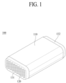
- FIG. 1 is a schematic perspective view of a hollow fiber membrane cartridge 100 according to an embodiment of the present disclosure.
- the hollow fiber membrane cartridge 100 may include an inner case 110, a plurality of hollow fiber membranes 120, a first potting portion 131, and a second potting portion 132.
- the inner case 110 may have an inner space.
- the inner case 110 may have a box shape with open ends. One of the open ends of the inner case 110 may be referred to as one side, and the other may be referred to as the other side.
- the plurality of hollow fiber membranes 120 may be disposed in the inner space of the inner case 110.
- FIG. 2 is a perspective view of a hollow fiber membrane 120 according to an embodiment of the present disclosure.
- the hollow fiber membrane 120 may have a hollow 121.
- the hollow fiber membrane 120 may have a tubular shape including a hollow center. Any commercially available hollow fiber membrane may be as the hollow fiber membrane 120.
- the first potting portion 131 may be coupled to one side of the inner case 110 to fix one side of each of the plurality of hollow fiber membranes 120.
- the second potting portion 132 may be coupled to the other side of the inner case 110 to fix the other side of each of the plurality of hollow fiber membranes 120.
- first potting portion 131 and the second potting portion 132 Opposite ends of the hollow fiber membrane cartridge 100 are potted by the first potting portion 131 and the second potting portion 132.
- the first potting portion 131 and the second potting portion 132 may be formed so as not to block the hollows of the plurality of hollow fiber membranes 120.
- the first potting portion 131 and the second potting portion 132 are typically formed by hardening a liquid polymer, such as a liquid polyurethane (PU) resin, using a casting method.
- PU liquid polyurethane
- An inner case 110 may have a heat distortion temperature of 120 °C or higher.
- the heat distortion temperature may be measured using a specimen of the inner case 110.
- the specimen of the inner case 110 is, for example, a specimen made of a material for the inner case.
- the specimen of the inner case 110 is also referred to as a "specimen”.
- the heat distortion temperature may be measured according to ASTM D 648.
- ASTM D 648 In order to measure the heat distortion temperature, an unannealed specimen having a thickness of 4 mm is prepared. The temperature at which the specimen is bent by 0.25 mm when a pressure stress of 1.8 MPa is applied to the specimen while the temperature is increased from room temperature (25 °C) at a rate of 2 °C/min is called the heat distortion temperature.
- the dimensions or shape of the inner case may be changed by a hot humidifying fluid. This may result in delamination of the adhesive interface between the first potting portion 131 and the inner case 110 or the adhesive interface between the second potting portion 132 and the inner case 110.
- the heat distortion temperature of the inner case 110 may be, for example, 140 °C or higher.
- the heat distortion temperature of the inner case 110 may be 150 °C or higher, or may be 160 °C or higher.
- the inner case 110 may have a hygroscopicity of 1% or less.
- the hygroscopicity may be obtained, for example, by immersing the specimen of the inner case 110 in water at 23 °C for 24 hours and then measuring the amount of moisture absorption of the specimen according to ASTM D 570.
- Hygroscopicity specimen weight after moisture absorption ⁇ initial specimen weight initial specimen weight ⁇ 100
- the hygroscopicity of the inner case 110 according to the embodiment of the present disclosure may be, for example, 0.5% or less, or may be 0.3% or less.
- the inner case 110 may include a polymer resin.
- the polymer resin may include at least one selected from among polyphenylene ether (PPE), polyphenylsulfone (PPSU), polysulfone (PSU), polyetheretherketone (PEEK), and polyarylate (PAR).
- PPE polyphenylene ether
- PPSU polyphenylsulfone
- PSU polysulfone
- PEEK polyetheretherketone
- PAR polyarylate
- Polyphenylene ether may be, for example, polyphenylene ether (m-PPE) modified by a polystyrene-butadiene copolymer (HIPS).
- m-PPE refers to polyphenylene ether (PPE) modified by a polystyrene-butadiene copolymer (HIPS) .
- m-PPE may include 90 to 99 wt% of polyphenylene ether (PPE) and 1 to 10 wt% of a polystyrene-butadiene copolymer (HIPS) based on the total weight of m-PPE.
- PPE polyphenylene ether
- HIPS polystyrene-butadiene copolymer
- polyphenylene ether If the content of polyphenylene ether (PPE) is less than 90 wt% based on the total weight of m-PPE, problems with heat resistance or mechanical strength may be caused, and if the content of polyphenylene ether (PPE) is more than 99 wt%, it is difficult to exhibit the properties of HIPS and problems with moldability may be caused, since the proportion of PPE is too large.
- m-PPE may have an Mw molecular weight (weight average molecular weight) of 70,000 to 100,000.
- the inner case 110 may have excellent hydrolysis resistance.
- the polymer constituting the inner case 110 may be hydrolyzed by a high-temperature, high-humidity humidifying fluid. In addition, this may cause the mechanical properties of the inner case 110 to rapidly deteriorate. As a result, delamination may occur between the inner case 110 and the potting portions 131 and 132 of the hollow fiber membrane cartridge 100.
- the hydrolysis resistance of the inner case 110 may be evaluated by a weight reduction rate of the inner case 110.
- the inner case 110 according to the embodiment of the present disclosure has excellent hydrolysis resistance, resulting in little or very little weight reduction even after high temperature and high humidity treatment.
- the inner case 110 may have a weight reduction rate (WR) of 10% or less.
- the weight reduction rate (WR) may be measured according to Equation 2 below.
- WR % W 1 ⁇ W 2 W 1 ⁇ 100
- W1 is the weight of the specimen of the inner case 110 before high temperature and high humidity treatment
- W2 is the weight of the specimen of the inner case 110 after the high temperature and high humidity treatment
- the specimen of the inner case 110 is placed in an autoclave containing water, the temperature of the autoclave is set to 120 °C ⁇ 3 °C, and high temperature and high humidity treatment is performed for 200 hours.
- a product from JAOTECH may be used as the autoclave.
- the delamination characteristics between the inner case 110 and the potting portions 131 and 132 may be evaluated.
- the hollow fiber membrane cartridge 100 may be subjected to high temperature and high humidity treatment, and delamination between the inner case 110 and the potting portions 131 and 132 may be checked.
- the autoclave may be used to subject the hollow fiber membrane cartridge 100 to high temperature and high humidity treatment.
- the hollow fiber membrane cartridge 100 is placed in an autoclave containing water, the temperature of the autoclave is set to 120 °C ⁇ 3 °C, and high temperature and high humidity treatment is performed for 200 hours.
- delamination between the inner case 110 and the potting portions 131 and 132 is evaluated as occurring when the inner case 110 and the potting portions 131 and 132 are spaced apart from each other or separated from each other.
- delamination between the inner case 110 and the potting portions 131 and 132 does not occur in the hollow fiber membrane cartridge 100 even after high temperature and high humidity treatment.
- delamination between the inner case 110 and the potting portions 131 and 132 does not occur, whereby failure of or damage to a humidifier or fuel cell including the inner case 110 may be prevented.
- the inner case 110 may have a coefficient of thermal expansion (CTE) of 100 ⁇ 10 -6 mm/mm/°C or less.
- CTE coefficient of thermal expansion
- the coefficient of thermal expansion may be measured, for example, using a thermomechanical analyzer (TMA) in accordance with a TMA-method and ASTM E 696.
- TMA thermomechanical analyzer
- ASTM E 696 ASTM E 696
- Q400 from TA Instrument may be used as the thermomechanical analyzer (TMA).
- the coefficient of thermal expansion is greater than 100 ⁇ 10 -6 mm/mm/°C, the dimensional changes may be increased by repeated temperature changes during use, and the resulting stress buildup may result in delamination of the adhesive interface between the inner case 110 and the potting portions 131 and 132 or failure of the humidifier or fuel cell including the inner case 110 due to breakage.
- the inner case 110 may have a specific gravity of 1.5 g/cm 3 or less.
- the specific gravity of the inner case 110 may be measured, for example, according to ASTM D 792.
- the inner case 110 according to the embodiment of the present disclosure may have low specific gravity while having excellent mechanical properties, which may contribute to a lightweight product design.
- FIG. 3 is a schematic exploded perspective view of a humidifier 200 for a fuel cell according to another embodiment of the present disclosure.
- the humidifier 200 for the fuel cell may include a mid-case 210, a first cap 221, and a second cap 222.
- the mid-case 210 may have an inner space. At least one hollow fiber membrane cartridge 100 may be disposed in the inner space of the mid-case 210.
- the mid-case 210 may have a box shape with open ends. One of the open ends of the mid-case 210 may be referred to as one end, and the other may be referred to as the other end.
- the first cap 221 may be coupled to one end of the mid-case 210.
- the second cap 222 may be coupled to the other end of the mid-case 210.
- a resin layer 213 may be disposed between the mid-case 210 and the hollow fiber membrane cartridge 100 to allow the hollow fiber membrane cartridge 100 to be fixed to the mid-case 210.
- the resin layer 213 may be disposed at one end and the other end of the mid-case 210.
- One space may be formed by the first cap 221 and the resin layer 213, and another space may be formed by the second cap 222 and the resin layer 213.
- a further space may be formed by the resin layer 213 disposed at one end of the mid-case 210 and the resin layer 213 disposed at the other end of the mid-case 210.
- the resin layer 213 may be disposed in the inner space of the mid-case 210, for example, using a casting method.
- the resin layer 213 may be formed by hardening a liquid polymer, such as a liquid polyurethane (PU) resin.
- PU liquid polyurethane
- the mid-case 210 may include an off-gas inlet 211 and an off-gas outlet 212. Off-gas introduced into the mid-case 210 through the off-gas inlet 211 may come into contact with outer surfaces of the plurality of hollow fiber membranes 120 and may be discharged from the mid-case 210 through the off-gas outlet 212. When the off-gas contacts the outer surfaces of the plurality of hollow fiber membranes 120, moisture contained in the off-gas may permeate the plurality of hollow fiber membranes 120, thereby humidifying air flowing along hollows of the plurality of hollow fiber membranes 120.
- a further embodiment of the present disclosure provides a fuel cell including a cell stack (not shown) and the humidifier 200 for the fuel cell connected to the cell stack.
- Polyurethane (PU) was prepared to form a first potting portion 131 and a second potting portion 132.
- the first potting portion 131 was formed on one side of the inner case 110 and the second potting portion 132 was formed on the other side of the inner case 110 such that the hollow fiber membranes 120 were fixed to the inner case 110 using a casting method.
- Example 1 As such, a hollow fiber membrane cartridge 100 according to Example 1 was manufactured.
- a hollow fiber membrane cartridge 100 was manufactured in the same manner as in (2) of Example 1, except that the inner case 110 made of polyphenylsulfone (PPSU) was used.
- PPSU polyphenylsulfone
- a hollow fiber membrane cartridge 100 was manufactured in the same manner as in (2) of Example 1, except that the inner case 110 made of polysulfone (PSU) was used.
- PSU polysulfone
- a hollow fiber membrane cartridge 100 was manufactured in the same manner as in (2) of Example 1, except that the inner case 110 made of polyetheretherketone (PEEK) was used.
- PEEK polyetheretherketone
- a hollow fiber membrane cartridge 100 was manufactured in the same manner as in (2) of Example 1, except that the inner case 110 made of polyarylate (PAR) was used.
- PAR polyarylate
- a hollow fiber membrane cartridge 100 was manufactured in the same manner as in (2) of Example 1, except that the inner case 110 made of polycarbonate (PC) was used.
- PC polycarbonate
- the physical properties of the inner cases 110 and the hollow fiber membrane cartridges 100 manufactured according to Examples 1 to 5 and the comparative example were measured. The following measurement methods were used.
- the hygroscopicity of the inner cases 110 manufactured according to Examples 1 to 5 and the comparative example was measured as follows.
- the weight of specimens of the inner cases 110 manufactured according to Examples 1 to 5 and the comparative examples was measured as the "initial specimen weight" after drying in an oven at 50 °C for 24 hours and cooling in a desiccator.
- the specimens of the inner cases 110 with the measured initial specimen weight were immersed in water at 23 °C for 24 hours, and the weight of the specimens after removing the specimens from the water and wiping moisture off the surface was measured as the "specimen weight after moisture absorption”.
- the amount of absorption (moisture absorption) of the specimens of the inner cases 110 was measured according to ASTM D 570 by comparing the "initial specimen weight" and the "specimen weight after moisture absorption".
- Hygroscopicity of the inner cases 110 manufactured according to Examples 1 to 5 and the comparative example was calculated according to Equation 1 below.
- Hygroscopicity % specimen weight after moisture absorption ⁇ initial specimen weight initial specimen weight ⁇ 100
- the specimen of the inner case 110 was placed in an autoclave containing water, the temperature of the autoclave was set to 120 °C ⁇ 3 °C, and high temperature and high humidity treatment was performed for 200 hours.
- W1 is the weight of the specimen of the inner case 110 before high temperature and high humidity treatment
- W2 is the weight of the specimen of the inner case 110 after the high temperature and high humidity treatment
- the delamination characteristics of the hollow fiber membrane cartridges 100 manufactured according to Examples 1 to 5 and the comparative example was evaluated by checking delamination between the inner case 110 and potting portions 131 and 132 after high temperature and high humidity treatment of the hollow fiber membrane cartridges 100 manufactured according to Examples 1 to 5 and the comparative example using an autoclave.
- the hollow fiber membrane cartridges 100 manufactured according to Examples 1 to 5 and the comparative example were placed in an autoclave containing water, the temperature of the autoclave was set to 120 °C ⁇ 3 °C, and high temperature and high humidity treatment was performed for 200 hours.
- CTE coefficient of thermal expansion
- the coefficient of linear thermal expansion of specimens of the inner cases 110 manufactured in Examples 1 to 5 and the comparative example at -30 to 30 °C was measured twice in accordance with a TMA-method and ASTM D 696, and the average value thereof was taken as the coefficient of thermal expansion (CTE).
- the dimensions of each of the specimens of the inner cases 110 was 6 mm (W) ⁇ 6 mm (L) ⁇ 4 mm (T), and the temperature increase rate was 5 °C/min.
- the specific gravity of the inner cases 110 manufactured according to Examples 1 to 5 and the comparative example was measured in accordance with ASTM D 792 using an underwater substitution method of calculating the specific gravity of each of the specimens of the inner cases 110 by measuring the mass of the specimen in air and measuring the apparent mass upon immersion in a liquid.
- Example 1 Polymer resin Heat distortion temperature (°C) Hygrosc opicity (%) Weight reduction rate (%) Delamination Coefficient of thermal expansion (mm/mm/°C) specific gravity (g/cm 3 )
- Example 1 m-PPE 145 °C 0.1% 6% X 60 ⁇ 10 -6 mm/mm/°C 1.1 g/cm 3
- Example 2 PPSU 180 °C 0.4% 8% X 50 ⁇ 10 -6 mm/mm/°C 1.4 g/cm 3
- Example 3 PSU 165 °C 0.5% 9% X 60 x 10 -6 mm/mm/°C 1.3 g/cm 3
- Example 4 PEEK 155 °C 0.15% 5% X 50 x 10 -6 mm/mm/°C 1.3 g/cm 3
- Example 5 PAR 175 °C 0.3% 7% X 60 x 10 -6 mm/mm/°C 1.2 g/cm 3 Comparative Example PC 117
- the inner cases 110 and the hollow fiber membrane cartridges 100 according to Examples 1 to 5 have excellent heat distortion temperature, excellent hydrolysis resistance, low hygroscopicity, a low coefficient of thermal expansion, and low specific gravity.
- the inner case 110 and the hollow fiber membrane cartridge 100 according to the comparative example have a high coefficient of thermal expansion and excellent specific gravity but have low heat distortion temperature and high hygroscopicity.
- the weight reduction rate of the specimen of the inner case 110 according to the comparative example was 40%.
Landscapes
- Chemical & Material Sciences (AREA)
- Chemical Kinetics & Catalysis (AREA)
- General Chemical & Material Sciences (AREA)
- Sustainable Development (AREA)
- Sustainable Energy (AREA)
- Life Sciences & Earth Sciences (AREA)
- Manufacturing & Machinery (AREA)
- Electrochemistry (AREA)
- Engineering & Computer Science (AREA)
- Health & Medical Sciences (AREA)
- Medicinal Chemistry (AREA)
- Polymers & Plastics (AREA)
- Organic Chemistry (AREA)
- Separation Using Semi-Permeable Membranes (AREA)
- Fuel Cell (AREA)
Abstract
Description
- The present disclosure relates to a hollow fiber membrane cartridge having heat resistance and hydrolysis resistance to a high-temperature, high-humidity humidifying fluid, a humidifier for a fuel cell, and a fuel cell including the same.
- A fuel cell is a power generation cell that combines hydrogen and oxygen to generate electricity. The fuel cell has advantages in that it is possible to continuously generate electricity as long as hydrogen and oxygen are supplied, unlike a general chemical cell, such as a dry cell or a storage cell, and in that there is no heat loss, whereby efficiency of the fuel cell is higher than efficiency of an internal combustion engine.
- In addition, the fuel cell directly converts chemical energy generated by combination of hydrogen and oxygen into electrical energy, whereby the amounts of contaminants that are discharged are small. Consequently, the fuel cell has advantages in that the fuel cell is environmentally friendly and in that a concern about depletion of resources due to an increase in energy consumption can be reduced.
- Among different types of fuel cells, a polymer electrolyte membrane fuel cell (PEMFC) is known as being favorable to a transportation system as well as small-scale stationary power generation equipment, since the polymer electrolyte membrane fuel cell is operated at low temperatures and the output density of the polymer electrolyte membrane fuel cell is high, whereby it is possible to miniaturize the polymer electrolyte membrane fuel cell.
- One of the important factors in improving the performance of the polymer electrolyte membrane fuel cell (PEMFC) is to supply more than a predetermined amount of moisture to a polymer electrolyte membrane or a proton exchange membrane (PEM) of a membrane electrode assembly (MEA) in order to retain moisture content. In order to retain the moisture content, humidification is required.
- A hollow fiber membrane having large transmission area per unit volume may be used as a permselective membrane used for humidification. When a humidifier is manufactured using the hollow fiber membrane, high integration of the hollow fiber membrane having large contact surface area is possible, whereby it is possible to sufficiently humidify the fuel cell even at a small capacity, it is possible to use a low-priced material, and it is possible to collect moisture and heat included in off-gas discharged from the fuel cell at high temperatures and to reuse the collected moisture and heat through the humidifier.
- During a humidification process in the humidifier using the hollow fiber membrane, the humidifier is used while being exposed to a high-temperature, high-humidity humidifying fluid, and therefore a material constituting the humidifier is required to be heat-resistant and hydrolysis-resistant. Consequently, it is necessary to develop a material for humidifiers having excellent heat resistance and hydrolysis resistance.
- An embodiment of the present disclosure, which has been made in view of the above, provides a hollow fiber membrane cartridge having excellent heat resistance.
- Another embodiment of the present disclosure provides a hollow fiber membrane cartridge having excellent hydrolysis resistance.
- Another embodiment of the present disclosure provides a hollow fiber membrane cartridge having excellent mechanical properties and dimensional stability.
- Another embodiment of the present disclosure seeks to provide a humidifier for a fuel cell including the hollow fiber membrane cartridge.
- A further embodiment of the present disclosure provides a fuel cell including the humidifier for a fuel cell.
- In order to accomplish the above objects, the embodiments of the present disclosure may include the following constructions.
- A hollow fiber membrane cartridge according to an embodiment of the present disclosure may include an inner case having an inner space, a plurality of hollow fiber membranes disposed in the inner space of the inner case, a first porting portion disposed on one side of the inner case, the first porting portion being configured to fix one side of each of the plurality of hollow fiber membranes, and a second porting portion disposed on the other side of the inner case, the second porting portion being configured to fix the other side of each of the plurality of hollow fiber membranes. The inner case may have a heat distortion temperature of 120 °C or higher and a hygroscopicity of 1% or less.
- The inner case may have a hygroscopicity of 0.5% or less.
- The inner case may include a polymer resin.
- The polymer resin may include at least one selected from among polyphenylene ether (PPE), polyphenylsulfone (PPSU), polysulfone (PSU), polyetheretherketone (PEEK), and polyarylate (PAR).
- Polyphenylene ether (PPE) may be polyphenylene ether (m-PPE) modified by a polystyrene-butadiene copolymer (HIPS).
- M-PPE may include 90 to 99 wt% of polyphenylene ether (PPE) and 1 to 10 wt% of a polystyrene-butadiene copolymer (HIPS) based on the total weight of m-PPE.
- The inner case may have a weight reduction rate of 10% or less after high temperature and high humidity treatment.
- Here, the high temperature and high humidity treatment means that the inner case is placed in an autoclave containing water, the temperature of the autoclave is set to 120 °C ± 3 °C, and high temperature and high humidity treatment is performed for 200 hours.
- The inner case may have a coefficient of thermal expansion (CTE) of 100 × 10-6 mm/mm/°C or less.
- The inner case may have a specific gravity of 1.5 g/cm3 or less.
- A humidifier for a fuel cell according to another embodiment of the present disclosure may include a mid-case having an inner space, an off-gas inlet, and an off-gas outlet, the hollow fiber membrane cartridge disposed in the inner space of the mid-case, a first cap coupled to one end of the mid-case, and a second cap coupled to the other end of the mid-case.
- A fuel cell according to a further embodiment of the present disclosure may include a cell stack and the humidifier connected to the cell stack.
- A hollow fiber membrane cartridge according to an embodiment of the present disclosure may have excellent heat resistance, and may have excellent hydrolysis resistance.
- In addition, the hollow fiber membrane cartridge according to the embodiment of the present disclosure may have excellent mechanical properties and dimensional stability.
- A humidifier for a fuel cell according to another embodiment of the present disclosure including the hollow fiber membrane cartridge may have excellent heat resistance, hydrolysis resistance, mechanical properties, and dimensional stability.
- A fuel cell according to a further embodiment of the present disclosure including the humidifier for the fuel cell may have excellent heat resistance, hydrolysis resistance, mechanical properties, and dimensional stability. The fuel cell according to the further embodiment of the present disclosure may have excellent durability and long lifespan characteristics, and may prevent or inhibit problems such as breakage or failure.
-
-
FIG. 1 is a schematic perspective view of a hollow fiber membrane cartridge according to an embodiment of the present disclosure. -
FIG. 2 is a perspective view of a hollow fiber membrane according to an embodiment of the present disclosure. -
FIG. 3 is a schematic exploded perspective view of a humidifier for a fuel cell according to another embodiment of the present disclosure. - The present disclosure may be variously changed and may have various embodiments, wherein specific embodiments will be described hereinafter in detail with reference to the accompanying drawings.
- When "have" or "include" mentioned in this specification is used, other parts may be added unless "only" is used. When a component is expressed in the singular, the component includes the plural unless otherwise expressly stated. Also, in interpreting a component, the component is interpreted as including an error range even if there is no explicit description thereof.
- Although the terms "first", "second", etc. may be used herein to describe various components, these components are not limited by the terms, and the terms are only used to distinguish one component from another.
-
FIG. 1 is a schematic perspective view of a hollowfiber membrane cartridge 100 according to an embodiment of the present disclosure. - Referring to
FIG. 1 , the hollowfiber membrane cartridge 100 according to the embodiment of the present disclosure may include aninner case 110, a plurality ofhollow fiber membranes 120, afirst potting portion 131, and asecond potting portion 132. - The
inner case 110 may have an inner space. Theinner case 110 may have a box shape with open ends. One of the open ends of theinner case 110 may be referred to as one side, and the other may be referred to as the other side. - The plurality of
hollow fiber membranes 120 may be disposed in the inner space of theinner case 110. -
FIG. 2 is a perspective view of ahollow fiber membrane 120 according to an embodiment of the present disclosure. - Referring to
FIG. 2 , thehollow fiber membrane 120 according to the embodiment of the present disclosure may have a hollow 121. For example, thehollow fiber membrane 120 may have a tubular shape including a hollow center. Any commercially available hollow fiber membrane may be as thehollow fiber membrane 120. - According to an embodiment of the present disclosure, one end of the tubular
hollow fiber membrane 120 is referred to as one side, and the other end is referred to as the other side. - The
first potting portion 131 may be coupled to one side of theinner case 110 to fix one side of each of the plurality ofhollow fiber membranes 120. Thesecond potting portion 132 may be coupled to the other side of theinner case 110 to fix the other side of each of the plurality ofhollow fiber membranes 120. - Opposite ends of the hollow
fiber membrane cartridge 100 are potted by thefirst potting portion 131 and thesecond potting portion 132. In this case, thefirst potting portion 131 and thesecond potting portion 132 may be formed so as not to block the hollows of the plurality ofhollow fiber membranes 120. Thefirst potting portion 131 and thesecond potting portion 132 are typically formed by hardening a liquid polymer, such as a liquid polyurethane (PU) resin, using a casting method. - An
inner case 110 according to an embodiment of the present disclosure may have a heat distortion temperature of 120 °C or higher. - The heat distortion temperature may be measured using a specimen of the
inner case 110. The specimen of theinner case 110 is, for example, a specimen made of a material for the inner case. Hereinafter, the specimen of theinner case 110 is also referred to as a "specimen". - According to an embodiment of the present disclosure, the heat distortion temperature may be measured according to ASTM D 648. In order to measure the heat distortion temperature, an unannealed specimen having a thickness of 4 mm is prepared. The temperature at which the specimen is bent by 0.25 mm when a pressure stress of 1.8 MPa is applied to the specimen while the temperature is increased from room temperature (25 °C) at a rate of 2 °C/min is called the heat distortion temperature.
- If the heat distortion temperature of the
inner case 110 is less than 120 °C, the dimensions or shape of the inner case may be changed by a hot humidifying fluid. This may result in delamination of the adhesive interface between thefirst potting portion 131 and theinner case 110 or the adhesive interface between thesecond potting portion 132 and theinner case 110. - The heat distortion temperature of the
inner case 110 according to the embodiment of the present disclosure may be, for example, 140 °C or higher. - More specifically, the heat distortion temperature of the
inner case 110 according to the embodiment of the present disclosure may be 150 °C or higher, or may be 160 °C or higher. - The
inner case 110 according to the embodiment of the present disclosure may have a hygroscopicity of 1% or less. - The hygroscopicity may be obtained, for example, by immersing the specimen of the
inner case 110 in water at 23 °C for 24 hours and then measuring the amount of moisture absorption of the specimen according to ASTM D 570. - The hygroscopicity may be measured by Equation 1 below.

- If the hygroscopicity is greater than 1%, continuous supply of a high-temperature, high-humidity humidifying fluid to the
inner case 110 may increase the probability of hydrolysis of theinner case 110, and may degrade the mechanical properties, resulting in breakage and failure of theinner case 110. - The hygroscopicity of the
inner case 110 according to the embodiment of the present disclosure may be, for example, 0.5% or less, or may be 0.3% or less. - The
inner case 110 according to the embodiment of the present disclosure may include a polymer resin. - The polymer resin may include at least one selected from among polyphenylene ether (PPE), polyphenylsulfone (PPSU), polysulfone (PSU), polyetheretherketone (PEEK), and polyarylate (PAR).
- Polyphenylene ether (PPE) may be, for example, polyphenylene ether (m-PPE) modified by a polystyrene-butadiene copolymer (HIPS). According to an embodiment of the present disclosure, m-PPE refers to polyphenylene ether (PPE) modified by a polystyrene-butadiene copolymer (HIPS) .
- According to an embodiment of the present disclosure, m-PPE may include 90 to 99 wt% of polyphenylene ether (PPE) and 1 to 10 wt% of a polystyrene-butadiene copolymer (HIPS) based on the total weight of m-PPE.
- If the content of polyphenylene ether (PPE) is less than 90 wt% based on the total weight of m-PPE, problems with heat resistance or mechanical strength may be caused, and if the content of polyphenylene ether (PPE) is more than 99 wt%, it is difficult to exhibit the properties of HIPS and problems with moldability may be caused, since the proportion of PPE is too large.
- According to an embodiment of the present disclosure, m-PPE may have an Mw molecular weight (weight average molecular weight) of 70,000 to 100,000.
- According to an embodiment of the present disclosure, the
inner case 110 may have excellent hydrolysis resistance. - If the
inner case 110 does not have hydrolysis resistance, the polymer constituting theinner case 110 may be hydrolyzed by a high-temperature, high-humidity humidifying fluid. In addition, this may cause the mechanical properties of theinner case 110 to rapidly deteriorate. As a result, delamination may occur between theinner case 110 and thepotting portions fiber membrane cartridge 100. - According to an embodiment of the present disclosure, the hydrolysis resistance of the
inner case 110 may be evaluated by a weight reduction rate of theinner case 110. - The
inner case 110 according to the embodiment of the present disclosure has excellent hydrolysis resistance, resulting in little or very little weight reduction even after high temperature and high humidity treatment. - The
inner case 110 according to the embodiment of the present disclosure may have a weight reduction rate (WR) of 10% or less. - The weight reduction rate (WR) may be measured according to Equation 2 below.

- In Equation 2, W1 is the weight of the specimen of the
inner case 110 before high temperature and high humidity treatment, and W2 is the weight of the specimen of theinner case 110 after the high temperature and high humidity treatment. - As high temperature and high humidity treatment conditions for measuring the weight reduction rate (WR) according to an embodiment of the present disclosure, the specimen of the
inner case 110 is placed in an autoclave containing water, the temperature of the autoclave is set to 120 °C ± 3 °C, and high temperature and high humidity treatment is performed for 200 hours. For example, a product from JAOTECH may be used as the autoclave. - According to an embodiment of the present disclosure, the
inner case 110 may have excellent hydrolysis resistance, whereby no or minimal shape deformation or chemical change of the inner case occurs even after high temperature and high humidity treatment. - As one method of evaluating the degree of shape deformation or chemical change of the
inner case 110, the delamination characteristics between theinner case 110 and thepotting portions - In order to evaluate the delamination characteristics, according to an embodiment of the present disclosure, the hollow
fiber membrane cartridge 100 may be subjected to high temperature and high humidity treatment, and delamination between theinner case 110 and thepotting portions fiber membrane cartridge 100 to high temperature and high humidity treatment. - As the high temperature and high humidity treatment conditions for evaluating the delamination characteristics according to an embodiment of the present disclosure, the hollow
fiber membrane cartridge 100 is placed in an autoclave containing water, the temperature of the autoclave is set to 120 °C ± 3 °C, and high temperature and high humidity treatment is performed for 200 hours. - According to an embodiment of the present disclosure, delamination between the
inner case 110 and thepotting portions inner case 110 and thepotting portions - According to an embodiment of the present disclosure, delamination between the
inner case 110 and thepotting portions fiber membrane cartridge 100 even after high temperature and high humidity treatment. - According to an embodiment of the present disclosure, delamination between the
inner case 110 and thepotting portions inner case 110 may be prevented. - The
inner case 110 according to the embodiment of the present disclosure may have a coefficient of thermal expansion (CTE) of 100 × 10-6 mm/mm/°C or less. - The coefficient of thermal expansion may be measured, for example, using a thermomechanical analyzer (TMA) in accordance with a TMA-method and ASTM E 696. For example, Q400 from TA Instrument may be used as the thermomechanical analyzer (TMA).
- If the coefficient of thermal expansion is greater than 100 × 10-6 mm/mm/°C, the dimensional changes may be increased by repeated temperature changes during use, and the resulting stress buildup may result in delamination of the adhesive interface between the
inner case 110 and thepotting portions inner case 110 due to breakage. - The
inner case 110 according to the embodiment of the present disclosure may have a specific gravity of 1.5 g/cm3 or less. - The specific gravity of the
inner case 110 may be measured, for example, according to ASTM D 792. Theinner case 110 according to the embodiment of the present disclosure may have low specific gravity while having excellent mechanical properties, which may contribute to a lightweight product design. -
FIG. 3 is a schematic exploded perspective view of ahumidifier 200 for a fuel cell according to another embodiment of the present disclosure. - Referring to
FIG. 3 , thehumidifier 200 for the fuel cell according to the other embodiment of the present disclosure may include a mid-case 210, afirst cap 221, and asecond cap 222. - The mid-case 210 may have an inner space. At least one hollow
fiber membrane cartridge 100 may be disposed in the inner space of the mid-case 210. - The mid-case 210 may have a box shape with open ends. One of the open ends of the mid-case 210 may be referred to as one end, and the other may be referred to as the other end.
- The
first cap 221 may be coupled to one end of the mid-case 210. Thesecond cap 222 may be coupled to the other end of the mid-case 210. - A
resin layer 213 may be disposed between the mid-case 210 and the hollowfiber membrane cartridge 100 to allow the hollowfiber membrane cartridge 100 to be fixed to the mid-case 210. For example, theresin layer 213 may be disposed at one end and the other end of the mid-case 210. - One space may be formed by the
first cap 221 and theresin layer 213, and another space may be formed by thesecond cap 222 and theresin layer 213. A further space may be formed by theresin layer 213 disposed at one end of the mid-case 210 and theresin layer 213 disposed at the other end of the mid-case 210. - The
resin layer 213 may be disposed in the inner space of the mid-case 210, for example, using a casting method. Theresin layer 213 may be formed by hardening a liquid polymer, such as a liquid polyurethane (PU) resin. - The mid-case 210 may include an off-
gas inlet 211 and an off-gas outlet 212. Off-gas introduced into the mid-case 210 through the off-gas inlet 211 may come into contact with outer surfaces of the plurality ofhollow fiber membranes 120 and may be discharged from the mid-case 210 through the off-gas outlet 212. When the off-gas contacts the outer surfaces of the plurality ofhollow fiber membranes 120, moisture contained in the off-gas may permeate the plurality ofhollow fiber membranes 120, thereby humidifying air flowing along hollows of the plurality ofhollow fiber membranes 120. - A further embodiment of the present disclosure provides a fuel cell including a cell stack (not shown) and the
humidifier 200 for the fuel cell connected to the cell stack. - Hereinafter, the present disclosure will be described with reference to more specific examples and a comparative example. However, the following examples are provided only for easier understanding of the present disclosure and do not limit the scope of the present disclosure.
-
- (1) Manufacture of
inner case 110
M-PPE (Mw molecular weight: 85,000) including polyphenylene ether (PPE) and a polystyrene-butadiene copolymer (HIPS), as a polymer resin, was melted and molded to manufacture aninner case 110 having an inner space. - (2) Manufacture of hollow
fiber membrane cartridge 100 - A bundle of
hollow fiber membranes 120 was placed in the inner space of theinner case 110. - Polyurethane (PU) was prepared to form a
first potting portion 131 and asecond potting portion 132. - The
first potting portion 131 was formed on one side of theinner case 110 and thesecond potting portion 132 was formed on the other side of theinner case 110 such that thehollow fiber membranes 120 were fixed to theinner case 110 using a casting method. - As such, a hollow
fiber membrane cartridge 100 according to Example 1 was manufactured. -
- (1) Manufacture of
inner case 110
Aninner case 110 was manufactured in the same manner as in (1) of Example 1, except that polyphenylsulfone (PPSU) was used instead of m-PPE. - (2) Manufacture of hollow
fiber membrane cartridge 100 - A hollow
fiber membrane cartridge 100 was manufactured in the same manner as in (2) of Example 1, except that theinner case 110 made of polyphenylsulfone (PPSU) was used. -
- (1) Manufacture of
inner case 110
Aninner case 110 was manufactured in the same manner as in (1) of Example 1, except that polysulfone (PSU) was used instead of m-PPE. - (2) Manufacture of hollow
fiber membrane cartridge 100 - A hollow
fiber membrane cartridge 100 was manufactured in the same manner as in (2) of Example 1, except that theinner case 110 made of polysulfone (PSU) was used. -
- (1) Manufacture of
inner case 110
Aninner case 110 was prepared in the same manner as in (1) of Example 1, except that polyetheretherketone (PEEK) was used instead of m-PPE. - (2) Manufacture of hollow
fiber membrane cartridge 100 - A hollow
fiber membrane cartridge 100 was manufactured in the same manner as in (2) of Example 1, except that theinner case 110 made of polyetheretherketone (PEEK) was used. -
- (1) Manufacture of
inner case 110
Aninner case 110 was manufactured in the same manner as in (1) of Example 1, except that polyarylate (PAR) was used instead of m-PPE. - (2) Manufacture of hollow
fiber membrane cartridge 100 - A hollow
fiber membrane cartridge 100 was manufactured in the same manner as in (2) of Example 1, except that theinner case 110 made of polyarylate (PAR) was used. -
- (1) Manufacture of
inner case 110
Aninner case 110 was manufactured in the same manner as in (1) of Example 1, except that polycarbonate (PC) was used instead of m-PPE. - (2) Manufacture of hollow
fiber membrane cartridge 100 - A hollow
fiber membrane cartridge 100 was manufactured in the same manner as in (2) of Example 1, except that theinner case 110 made of polycarbonate (PC) was used. - The physical properties of the
inner cases 110 and the hollowfiber membrane cartridges 100 manufactured according to Examples 1 to 5 and the comparative example were measured. The following measurement methods were used. -
- 1) The heat distortion temperature of the
inner cases 110 manufactured according to Examples 1 to 5 and the comparative example was obtained by supporting opposite ends of a specimen in a heating bath, increasing the temperature of a heating medium from room temperature (25 °C) at a rate of 2 °C/min while applying a predetermined bending stress in the state in which a rod was in contact with the center of the specimen, and measuring the temperature of the heating medium when bending of the specimen reached a predetermined value. - 2) More specifically, the heat distortion temperature of the
inner cases 110 manufactured according to Examples 1 to 5 and the comparative example was measured according to ASTM D 648. In order to measure the heat distortion temperature, specimens according to Examples 1 to 5 and the Comparative Example in an unannealed state having a thickness of 4 mm were prepared and placed in a heating bath as described in 1), a pressure stress of 1.8 MPa was applied to the specimens while the temperature of a heating medium was increased from room temperature (25 °C) at a rate of 2 °C/min, and the temperature when each specimen was bent by 0.25 mm was measured as the heat distortion temperature (HDT). - The hygroscopicity of the
inner cases 110 manufactured according to Examples 1 to 5 and the comparative example was measured as follows. - The weight of specimens of the
inner cases 110 manufactured according to Examples 1 to 5 and the comparative examples was measured as the "initial specimen weight" after drying in an oven at 50 °C for 24 hours and cooling in a desiccator. The specimens of theinner cases 110 with the measured initial specimen weight were immersed in water at 23 °C for 24 hours, and the weight of the specimens after removing the specimens from the water and wiping moisture off the surface was measured as the "specimen weight after moisture absorption". Subsequently, the amount of absorption (moisture absorption) of the specimens of theinner cases 110 was measured according to ASTM D 570 by comparing the "initial specimen weight" and the "specimen weight after moisture absorption". - The hygroscopicity of the
inner cases 110 manufactured according to Examples 1 to 5 and the comparative example was calculated according to Equation 1 below.
- The weight reduction rate (WR) of the
inner cases 110 manufactured according to Examples 1 to 5 and the comparative examples was measured by subjecting specimens of theinner cases 110 manufactured according to Examples 1 to 5 and the comparative example to high temperature and high humidity treatment using an autoclave. - As high temperature and high humidity treatment conditions for measuring the weight reduction rate (WR) according to an embodiment of the present disclosure, the specimen of the
inner case 110 was placed in an autoclave containing water, the temperature of the autoclave was set to 120 °C ± 3 °C, and high temperature and high humidity treatment was performed for 200 hours. - The weight reduction rate (WR) of the
inner cases 110 manufactured according to Examples 1 to 5 and the comparative example was calculated according to Equation 2 below.
- In Equation 2, W1 is the weight of the specimen of the
inner case 110 before high temperature and high humidity treatment, and W2 is the weight of the specimen of theinner case 110 after the high temperature and high humidity treatment. - The delamination characteristics of the hollow
fiber membrane cartridges 100 manufactured according to Examples 1 to 5 and the comparative example was evaluated by checking delamination between theinner case 110 andpotting portions fiber membrane cartridges 100 manufactured according to Examples 1 to 5 and the comparative example using an autoclave. - As the high temperature and high humidity treatment conditions for evaluating the delamination characteristics according to an embodiment of the present disclosure, the hollow
fiber membrane cartridges 100 manufactured according to Examples 1 to 5 and the comparative example were placed in an autoclave containing water, the temperature of the autoclave was set to 120 °C ± 3 °C, and high temperature and high humidity treatment was performed for 200 hours. - When the
inner case 110 and thepotting portions inner case 110 and thepotting portions - The coefficient of thermal expansion (CTE) of the
inner cases 110 manufactured according to Examples 1 to 5 and the comparative example was measured using a TMA (TA Instrument, Q400). - Specifically, the coefficient of linear thermal expansion of specimens of the
inner cases 110 manufactured in Examples 1 to 5 and the comparative example at -30 to 30 °C was measured twice in accordance with a TMA-method and ASTM D 696, and the average value thereof was taken as the coefficient of thermal expansion (CTE). The dimensions of each of the specimens of theinner cases 110 was 6 mm (W) × 6 mm (L) × 4 mm (T), and the temperature increase rate was 5 °C/min. - The specific gravity of the
inner cases 110 manufactured according to Examples 1 to 5 and the comparative example was measured in accordance with ASTM D 792 using an underwater substitution method of calculating the specific gravity of each of the specimens of theinner cases 110 by measuring the mass of the specimen in air and measuring the apparent mass upon immersion in a liquid. - The results of measurements are shown in Table 1 below.
[Table 1] Polymer resin Heat distortion temperature (°C) Hygrosc opicity (%) Weight reduction rate (%) Delamination Coefficient of thermal expansion (mm/mm/°C) specific gravity (g/cm3) Example 1 m-PPE 145 °C 0.1% 6% X 60 × 10-6 mm/mm/°C 1.1 g/cm3 Example 2 PPSU 180 °C 0.4% 8% X 50 × 10-6 mm/mm/°C 1.4 g/cm3 Example 3 PSU 165 °C 0.5% 9% X 60 x 10-6 mm/mm/°C 1.3 g/cm3 Example 4 PEEK 155 °C 0.15% 5% X 50 x 10-6 mm/mm/°C 1.3 g/cm3 Example 5 PAR 175 °C 0.3% 7% X 60 x 10-6 mm/mm/°C 1.2 g/cm3 Comparative Example PC 117 °C 1. 5% 40% O 80 x 10-6 mm/mm/°C 1.2 g/cm3 - Referring to Table 1, it can be seen that the
inner cases 110 and the hollowfiber membrane cartridges 100 according to Examples 1 to 5 have excellent heat distortion temperature, excellent hydrolysis resistance, low hygroscopicity, a low coefficient of thermal expansion, and low specific gravity. In contrast, it can be seen that theinner case 110 and the hollowfiber membrane cartridge 100 according to the comparative example have a high coefficient of thermal expansion and excellent specific gravity but have low heat distortion temperature and high hygroscopicity. - In particular, after high temperature and high humidity treatment using the autoclave, the weight reduction rate of the specimen of the
inner case 110 according to the comparative example was 40%. - In addition, after high temperature and high humidity treatment using the autoclave, delamination appears between the
inner case 110 and thepotting portions fiber membrane cartridge 100 according to the comparative example, which indicates a lack of hydrolysis resistance. - The above description has been made merely to illustrate the technical idea of the present disclosure, and those skilled in the art will appreciate that various variations and modifications are possible without departing from the intrinsic features of the present disclosure. In addition, the embodiments disclosed in the present disclosure are provided to describe the technical idea of the present disclosure, rather than to limit the technical idea of the present disclosure, and the scope of the technical idea of the present disclosure is not limited by the embodiments. Therefore, the scope of protection of the present disclosure should be determined by the appended claims, and all technical ideas within the range equivalent to the appended claims should be understood as falling within the scope of rights of the present disclosure.
-
- 100: Hollow fiber membrane cartridge 110: Inner case
- 120: Hollow fiber membrane 121: Hollow
- 131: First potting portion 132: Second potting portion
- 200: Humidifier for a fuel cell 210: Mid-case
- 211: Off-gas inlet 212: Off-gas outlet
- 213: Resin layer 221: First cap
- 222: Second cap
Claims (11)
- A hollow fiber membrane cartridge comprising:an inner case having an inner space;a plurality of hollow fiber membranes disposed in the inner space of the inner case;a first porting portion disposed on one side of the inner case, the first porting portion being configured to fix one side of each of the plurality of hollow fiber membranes; anda second porting portion disposed on the other side of the inner case, the second porting portion being configured to fix the other side of each of the plurality of hollow fiber membranes,wherein the inner case has a heat distortion temperature of 120 °C or higher and a hygroscopicity of 1% or less.
- The hollow fiber membrane cartridge according to claim 1, wherein the inner case has a hygroscopicity of 0.5% or less.
- The hollow fiber membrane cartridge according to claim 1, wherein the inner case comprises a polymer resin.
- The hollow fiber membrane cartridge according to claim 3, wherein the polymer resin comprises at least one selected from among polyphenylene ether (PPE), polyphenylsulfone (PPSU), polysulfone (PSU), polyetheretherketone (PEEK), and polyarylate (PAR).
- The hollow fiber membrane cartridge according to claim 4, wherein polyphenylene ether (PPE) is polyphenylene ether (m-PPE) modified by a polystyrene-butadiene copolymer (HIPS).
- The hollow fiber membrane cartridge according to claim 5, wherein m-PPE comprises 90 to 99 wt% of polyphenylene ether (PPE) and 1 to 10 wt% of a polystyrene-butadiene copolymer (HIPS) based on a total weight of m-PPE.
- The hollow fiber membrane cartridge according to claim 1, whereinthe inner case has a weight reduction rate of 10% or less after high temperature and high humidity treatment,the high temperature and high humidity treatment meaning that the inner case is placed in an autoclave containing water, a temperature of the autoclave is set to 120 °C ± 3 °C, and high temperature and high humidity treatment is performed for 200 hours.
- The hollow fiber membrane cartridge according to claim 1, wherein the inner case has a coefficient of thermal expansion (CTE) of 100 x 10-6 mm/mm/°C or less.
- The hollow fiber membrane cartridge according to claim 1, wherein the inner case has a specific gravity of 1.5 g/cm3 or less.
- A humidifier for a fuel cell, the humidifier comprising:a mid-case having an inner space, an off-gas inlet, and an off-gas outlet;the hollow fiber membrane cartridge according to any one of claims 1 to 9, the hollow fiber membrane cartridge being disposed in the inner space of the mid-case;a first cap coupled to one end of the mid-case; anda second cap coupled to the other end of the mid-case.
- A fuel cell comprising:a cell stack; andthe humidifier according to claim 10, the humidifier being connected to the cell stack.
Applications Claiming Priority (2)
| Application Number | Priority Date | Filing Date | Title |
|---|---|---|---|
| KR1020220097446A KR102759726B1 (en) | 2022-08-04 | 2022-08-04 | Cartridge of Hollow Fiber Membrane, Humidifier for Fuel Cell and Fuel Cell comprising the same |
| PCT/KR2023/010918 WO2024029840A1 (en) | 2022-08-04 | 2023-07-27 | Hollow fiber membrane cartridge, humidifier for fuel cell, and fuel cell including same |
Publications (1)
| Publication Number | Publication Date |
|---|---|
| EP4541452A1 true EP4541452A1 (en) | 2025-04-23 |
Family
ID=89849339
Family Applications (1)
| Application Number | Title | Priority Date | Filing Date |
|---|---|---|---|
| EP23850344.5A Pending EP4541452A1 (en) | 2022-08-04 | 2023-07-27 | Hollow fiber membrane cartridge, humidifier for fuel cell, and fuel cell including same |
Country Status (6)
| Country | Link |
|---|---|
| EP (1) | EP4541452A1 (en) |
| JP (1) | JP7864929B2 (en) |
| KR (1) | KR102759726B1 (en) |
| CN (1) | CN119630469A (en) |
| CA (1) | CA3262141A1 (en) |
| WO (1) | WO2024029840A1 (en) |
Family Cites Families (11)
| Publication number | Priority date | Publication date | Assignee | Title |
|---|---|---|---|---|
| JPH09206564A (en) * | 1996-02-08 | 1997-08-12 | Kanegafuchi Chem Ind Co Ltd | Hollow fiber membrane module and manufacturing method thereof |
| JP2006302706A (en) | 2005-04-21 | 2006-11-02 | Toyota Motor Corp | Humidifier for fuel cell |
| US8307991B2 (en) * | 2006-09-19 | 2012-11-13 | Toray Industries Inc. | Hollow fiber membrane module |
| JP5137465B2 (en) * | 2007-05-28 | 2013-02-06 | 旭有機材工業株式会社 | valve |
| JP5354248B2 (en) | 2008-03-05 | 2013-11-27 | Nok株式会社 | Humidifying membrane module |
| KR101757578B1 (en) * | 2015-03-10 | 2017-07-13 | 주식회사 엘지화학 | Modified poly(arylene ether) resin composition and molded article produced thereof |
| JP6591782B2 (en) * | 2015-05-18 | 2019-10-16 | ユニチカ株式会社 | Polyarylate hollow fiber membrane, production method thereof, and hollow fiber membrane module |
| KR102186187B1 (en) * | 2016-12-29 | 2020-12-03 | 코오롱인더스트리 주식회사 | Method of hollow fiber membrane module and hollow fiber membrane module using it |
| JP7402249B2 (en) | 2019-04-17 | 2023-12-20 | コーロン インダストリーズ インク | Humidifier for fuel cells and packing materials for it |
| JP7505339B2 (en) * | 2019-09-24 | 2024-06-25 | 東レ株式会社 | Hollow fiber membrane bundle containing module and manufacturing method thereof |
| KR20220043352A (en) * | 2020-09-29 | 2022-04-05 | 코오롱인더스트리 주식회사 | Cartridge of Humidifier for Fuel Cell and Humidifier for Fuel Cell |
-
2022
- 2022-08-04 KR KR1020220097446A patent/KR102759726B1/en active Active
-
2023
- 2023-07-27 CA CA3262141A patent/CA3262141A1/en active Pending
- 2023-07-27 CN CN202380057052.XA patent/CN119630469A/en active Pending
- 2023-07-27 EP EP23850344.5A patent/EP4541452A1/en active Pending
- 2023-07-27 JP JP2025502451A patent/JP7864929B2/en active Active
- 2023-07-27 WO PCT/KR2023/010918 patent/WO2024029840A1/en not_active Ceased
Also Published As
| Publication number | Publication date |
|---|---|
| WO2024029840A1 (en) | 2024-02-08 |
| KR102759726B1 (en) | 2025-01-23 |
| CN119630469A (en) | 2025-03-14 |
| JP2025525734A (en) | 2025-08-07 |
| CA3262141A1 (en) | 2025-06-13 |
| JP7864929B2 (en) | 2026-05-25 |
| KR20240019587A (en) | 2024-02-14 |
Similar Documents
| Publication | Publication Date | Title |
|---|---|---|
| Tang et al. | Properties and stability of quaternary ammonium-biphosphate ion-pair poly (sulfone) s high temperature proton exchange membranes for H2/O2 fuel cells | |
| US20150171454A1 (en) | Membrane with laminated structure and orientation controlled nanofiber reinforcement additives for fuel cells | |
| WO2007090072A2 (en) | Apparatus and methods for electrochemical hydrogen manipulation | |
| Hao et al. | Accelerated degradation of quaternary ammonium functionalized anion exchange membrane in catholyte of vanadium redox flow battery | |
| Gao et al. | Stable anion exchange membranes derived from fluorinated poly (aryl ethers) with quaternized fluorene units for fuel cell applications | |
| US20050069745A1 (en) | Polymer electrolyte membranes for use in fuel cells | |
| US20060159975A1 (en) | Polymer electrolyte and fuel cell using the same | |
| CN104341607A (en) | Application of polybenzimidazole polymer containing side group in proton exchange membrane | |
| KR101085358B1 (en) | Hydrocarbon-based polymer membrane comprising a silane compound, a manufacturing method thereof, a membrane-electrode assembly and a fuel cell comprising the same | |
| Güler et al. | Characterization and fuel cell performance of divinylbenzene crosslinked phosphoric acid doped membranes based on 4-vinylpyridine grafting onto poly (ethylene-co-tetrafluoroethylene) films | |
| EP2437338B1 (en) | Proton-conductive polymer electrolyte membrane, and membrane-electrode assembly and polymer electrolyte fuel cell using the same | |
| JP2003297385A (en) | Method of manufacturing fuel cell separator, fuel cell separator, and polymer electrolyte fuel cell | |
| US8354201B2 (en) | Fuel cell with spatially non-homogeneous ionic membrane | |
| WO2004073085A2 (en) | High temperature composite proton exchange membranes | |
| KR102759726B1 (en) | Cartridge of Hollow Fiber Membrane, Humidifier for Fuel Cell and Fuel Cell comprising the same | |
| CN119890375B (en) | A phosphoric acid-doped polybenzimidazole high-temperature proton exchange membrane and its preparation method | |
| Lee et al. | Sulfonated polyimide and poly (ethylene glycol) diacrylate based semi‐interpenetrating polymer network membranes for fuel cells | |
| WO2025243038A2 (en) | Water electrolyser membrane | |
| US20140080031A1 (en) | Dual Layered ePTFE Polyelectrolyte Membranes | |
| KR101865941B1 (en) | Sulfonated poly(phenylene sulfide sulfone nitrile) and Membrane for Fuel Cell Application using it | |
| Çalı et al. | The chemical crosslinking effect of polybenzimidazole/polyvinyl alcohol blend membranes for proton exchange membrane fuel cells: An experimental study | |
| US20060228607A1 (en) | Fuel cell and membrane-electrode assembly thereof | |
| Tatsukawa et al. | Heat Treatment for a Membrane Composed of Polymer Nanofibers and a Perfluorosulfonic-Acid Polymer Matrix: Effect on Proton-Exchange-Membrane Properties | |
| JP5029875B2 (en) | Surface modification method of resin molding board by sulfur trioxide gas. | |
| KR100637211B1 (en) | Polymer electrolyte and fuel cell using the same |
Legal Events
| Date | Code | Title | Description |
|---|---|---|---|
| STAA | Information on the status of an ep patent application or granted ep patent |
Free format text: STATUS: THE INTERNATIONAL PUBLICATION HAS BEEN MADE |
|
| PUAI | Public reference made under article 153(3) epc to a published international application that has entered the european phase |
Free format text: ORIGINAL CODE: 0009012 |
|
| STAA | Information on the status of an ep patent application or granted ep patent |
Free format text: STATUS: REQUEST FOR EXAMINATION WAS MADE |
|
| 17P | Request for examination filed |
Effective date: 20250115 |
|
| AK | Designated contracting states |
Kind code of ref document: A1 Designated state(s): AL AT BE BG CH CY CZ DE DK EE ES FI FR GB GR HR HU IE IS IT LI LT LU LV MC ME MK MT NL NO PL PT RO RS SE SI SK SM TR |
|
| DAV | Request for validation of the european patent (deleted) | ||
| DAX | Request for extension of the european patent (deleted) | ||
| RIC1 | Information provided on ipc code assigned before grant |
Ipc: B01D 63/02 20060101AFI20260429BHEP Ipc: H01M 8/04119 20160101ALI20260429BHEP Ipc: C08L 71/12 20060101ALI20260429BHEP Ipc: C08L 25/10 20060101ALI20260429BHEP |