EP4541440A1 - Splitter device of or for a belay system of or for an amusement facility, belay system including such a splitter device and amusement facility being equipped with such a belay system - Google Patents
Splitter device of or for a belay system of or for an amusement facility, belay system including such a splitter device and amusement facility being equipped with such a belay system Download PDFInfo
- Publication number
- EP4541440A1 EP4541440A1 EP23203893.5A EP23203893A EP4541440A1 EP 4541440 A1 EP4541440 A1 EP 4541440A1 EP 23203893 A EP23203893 A EP 23203893A EP 4541440 A1 EP4541440 A1 EP 4541440A1
- Authority
- EP
- European Patent Office
- Prior art keywords
- splitter device
- belay
- rotational position
- trolley
- amusement facility
- Prior art date
- Legal status (The legal status is an assumption and is not a legal conclusion. Google has not performed a legal analysis and makes no representation as to the accuracy of the status listed.)
- Granted
Links
Images



Classifications
-
- A—HUMAN NECESSITIES
- A63—SPORTS; GAMES; AMUSEMENTS
- A63B—APPARATUS FOR PHYSICAL TRAINING, GYMNASTICS, SWIMMING, CLIMBING, OR FENCING; BALL GAMES; TRAINING EQUIPMENT
- A63B9/00—Climbing poles, frames, or stages
-
- A—HUMAN NECESSITIES
- A63—SPORTS; GAMES; AMUSEMENTS
- A63G—MERRY-GO-ROUNDS; SWINGS; ROCKING-HORSES; CHUTES; SWITCHBACKS; SIMILAR DEVICES FOR PUBLIC AMUSEMENT
- A63G21/00—Chutes; Helter-skelters
- A63G21/20—Slideways with movably suspended cars, or with cars moving on ropes, or the like
-
- A—HUMAN NECESSITIES
- A63—SPORTS; GAMES; AMUSEMENTS
- A63G—MERRY-GO-ROUNDS; SWINGS; ROCKING-HORSES; CHUTES; SWITCHBACKS; SIMILAR DEVICES FOR PUBLIC AMUSEMENT
- A63G21/00—Chutes; Helter-skelters
- A63G21/22—Suspended slideways
-
- A—HUMAN NECESSITIES
- A63—SPORTS; GAMES; AMUSEMENTS
- A63B—APPARATUS FOR PHYSICAL TRAINING, GYMNASTICS, SWIMMING, CLIMBING, OR FENCING; BALL GAMES; TRAINING EQUIPMENT
- A63B9/00—Climbing poles, frames, or stages
- A63B2009/004—Three-dimensional rope or cable networks
Definitions
- the present invention relates to a splitter device of or for a belay system of or for an amusement facility. Moreover, the present invention is drawn to a belay system including such a splitter device and an amusement facility being equipped with such a belay system.
- Such amusement facilities reference is made to in the following may have a tower-like structure with a plurality of floors.
- a belay system with a rail-like guiding track is arranged along which a plurality of belay trolleys can be moved.
- the guiding track laterally extends from the tower-like structure.
- a given user of the amusement facility is wearing a harness which can be connected to the belay trolley e.g., by a lanyard and a carabiner.
- the belay trolley comprises at least one mounting hole through which the lanyard and the carabiner can be passed for connecting.
- An obstacle course is arranged below the belay system along which a user may walk.
- the obstacle course may comprise rope ladders, rope-secured paths and the like.
- the obstacle course is freely hung on structure or support elements of the amusement facility and as such does not have any security means to prevent the user from falling from the obstacle course.
- the belay system that prevents the user from falling from the obstacle course is hardly conceivable by the user. Therefore, the user experiences a high degree of thrill when waking along the obstacle course.
- connection between the harness and the belay trolley may allow for a relative rotation between them.
- the user may turn by 180° and walk along the obstacle in the opposite direction.
- a belay system that is used in climbing arrangements is disclosed in WO 2017/005504 A1 .
- the belay system comprises a rail-like guiding track along which a plurality of belay trolleys can be moved, usually one belay trolley per person.
- the guiding track and thus the obstacle course typically run in loops around the vertical axis of the tower-like structure of the amusement facility.
- the user can enter the obstacle course at various access points located on each floor such that it is not necessary to completely circulate the vertical axis. If the user wants to omit parts of the obstacle course, he can go back to the next access point to leave the obstacle course and return to the floor, thereby releasing the lanyard from his harness. He can then take the adjacent or another access point to enter the obstacle course again by fixing the lanyard of a given belay trolley to his harness.
- the present invention seeks to present a way to facilitate the omission of parts of the obstacle course of a given amusement facility without compromising the security of the users, at the same time enabling the economic operation of the amusement facility.
- a belay system comprises a rail-like guiding track on which at least one belay trolley can be moved and which forms at least a first free end, a second free end and a third free end arranged angularly to each other in a reference plain.
- a splitter device of or for this belay system of or for an amusement facility comprises a rail-like guiding track
- guiding tracks are closed in itself, meaning that the belay trolley could be moved along one fixed path only. Junctions or crossings are not possible.
- two or more sections of a guiding track can be connected to each other without the need that the user has to disconnect and reconnect the harness to the lanyard of a given belay trolley.
- a network of guiding track sections can be established and flexibly connected to each other. The user can choose which segment of the obstacle course he wants take and which section he wishes to omit without a significant delay. Segments the user prefers the most may be taken again. As mentioned, there is no need to disconnect and reconnect the harness to the lanyard of a given belay trolley.
- the guiding section connects two free ends, e.g., the first free end and the second free end which may form a first pair of the three free ends. In another rotational position, the guiding section connects the first free and the third free end which may form a second pair of the three free ends.
- the shifting body is in a first rotational position in which a first end and a second end of the guiding track are connected by the guiding section.
- the guiding section is flush with the first end and the second end. If the user wants to go straight on the obstacle course, the belay trolley is moved via the first end, the guiding section and the second end.
- the user wants to leave a segment and enter another segment of the obstacle course, he moves the belay trolley via the first end onto the guiding section of the shifting body and then stops. After that, the shifting body and thus the guiding section are rotated such that the guiding section is flush with a third end of the guiding track which is associated with another segment of the obstacle course. The user can then enter into this segment via the third end and continue the walk along the obstacle course.
- the guiding section comprises positioning means for positioning the belay trolley on the guiding system.
- the belay trolley has to be placed on the guiding section of the splitter device for entering another section of the guiding track. It may, however, be difficult for the user to estimate whether the belay trolley is located on the guiding section or not.
- the positioning means help positioning the belay trolley within the guiding section and give the user respective feedback.
- the positioning means may be embodied by indentations and/or by a radius of the guiding section. In both cases the user has to employ a higher force for moving the belay trolley out of the positioning means than outside the positioning means. The user thereby gets a kind of haptic feedback which indicates that the shifting body can be rotated. The operational comfort is thereby increased and maloperations reduced.
- the splitter device comprises a retaining unit for retaining the belay trolley on the guiding section when the shifting body is moved between the first rotational position and the second rotational position.
- the retaining unit may be a shield or the like mounted on the mounting body. The retaining unit prevents the belay trolley from leaving the guiding section when the same is moved between the first rotational position to the second rotational position. Thereby, the belay trolley is prevented from derailing from the guiding track.
- the splitter device comprises a position presetting unit for setting the first rotational position and the second rotational position.
- the shifting body may for example be rotated by 90° or 120° to connect the respective ends of the guiding track with each other.
- the setting unit facilitates the setting of the shifting body into the first or second rotational position and prevents placing the shifting body into an intermediate position on which no ends of the guiding track are connected to each other. Maloperations are prevented and the operational comfort increased.
- the setting element may interact with the shaft in a specific way when the same is in the first or second rotational position. Such a specific interaction could be realized in that the rotation out of the first or second rotational position is prevented unless a button is pressed or an increased turning force is applied.
- slotted guides, locking bolts, brackets or the like may be used which are fairly simple and reliable elements such that maloperations can be avoided with little effort.
- a further embodiment provides that a cam disk is mounted on the shaft and the setting element comprises a preload unit for preloading the setting element against the cam disk.
- the cam disk may have recesses that are associated to the first and the second rotational position in which the preload unit is maximally relaxed. In case the shifting body is moved out of the first rotational position, the preload unit is preloaded for which a respective turning force is needed. As a result, the user who rotates the shifting body gets feedback depending on the rotational position of the shifting body.
- the position presetting unit comprises a magnet unit.
- the use of a magnet unit for setting the first rotational position and the second rotational position enables a simple and space-saving construction of the position presetting unit.
- the splitter device comprises a gripping section by which a user can manually rotate the shifting body between the first rotational position and the second rotational position.
- the user manually rotates the shifting body between the first rotational position and the second rotational position.
- the shifting body is equipped with gripping sections which the user can easily reach.
- the gripping sections may be provided by solid handles or by loops provided by ropes which are fastened to the shifting body.
- the splitter device comprises a drive unit for rotating the shifting body between the first rotational position and the second rotational position.
- the user manually rotates the shifting body.
- a further embodiment provides at least one blocking member is provided on the guiding section which is movable between a blocking position in which the movement of the belay trolley along the guiding section is blocked and a release position in which the movement of the belay trolley along the guiding section is released.
- the blocking member may be used in different ways: In a first way, the belay trolley is immobilized on the guiding section at least as long as the shifting body is rotated to avoid derailment of the belay trolley from the guiding section and/or the guiding track. In another way, the belay trolley may be removed from the guiding section only in one direction. This may be advantageous when a given segment of the obstacle course should be taken in one direction only. Certain segments of the obstacle course can be closed and the traffic along the obstacle course routed, in particular for avoiding congestions.
- the splitter device comprises a locking element by which the rotation of the shifting body around the rotation axis can be locked and released.
- the locking element also serves for routing the traffic along the obstacle course. In particular when many users are walking along the obstacle course, it may be necessary to close certain segments which can be done by locking the shifting body such that the user cannot freely decide which segment to take.
- Another implementation of the invention is directed towards a belay system of or for an amusement facility, comprising
- the user may decide to omit certain segments of the obstacle course or to take certain segments further times without the need to disconnect and reconnect the harness to the lanyard of a given belay trolley.
- the belay system comprises a positioning detection unit for detecting the position of the belay trolley on the guiding track.
- the positioning detection unit provides an information of the position of a given belay trolley within the guiding track. This information may be used to activate the blocking member or the locking element to route the traffic along the obstacle course, in particular to avoid the accumulation of many users within the same segment which may lead to a congestion.
- An additional aspect of the present refers to an amusement facility comprising a belay system according to one of the implementations previously described.
- the technical effects and advantages as discussed with regard to the present splitter device equally apply to the amusement facility.
- One embodiment of the amusement facility comprises a number of floors, in particular a plurality of floors, wherein at least one belay system according to one of the implementations described above is arranged on each floor.
- the technical effects and advantages as discussed with regard to the present splitter device equally apply to this embodiment the amusement facility.
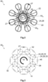
- Figure 1A shows a principle top sectional view and Figure 1B a principal side sectional view of an amusement facility 10 according to the prior art.
- the amusement facility 10 has a tower-like structure which may comprise beams, struts 12 and the like such that a scaffold is formed.
- the amusement facility 10 has at least one floor 14 elevated by a certain distance from the ground.
- the amusement facility 10 comprises at least one floor 14 that is accessible by stairways 16, escalators and/or elevators or the like.
- a panoramic roof 18 which includes a viewing platform is typically arranged above the highest floor 14.
- the amusement facility 10 shown in Figure 1 comprises in total three floors 14.
- an obstacle course 20 is arranged which may comprise rope ladders 21, rope loops and the like such that no continuous and stable path is formed.
- particular obstacles 22 like car tires, climbing walls (not shown) and the like may also be provided to further aggravate the walk along the obstacle course 20.
- only some obstacles 22 are shown. However, the number of obstacles 22 can be freely chosen.
- the amusement facility 10 is provided with belay system 24.
- the belay system 24 is equipped with a rail-like guiding track 26 along which one or more belay trolleys 27 can be moved.
- the obstacle course 20 follows the course of the guiding track 26.
- the obstacles 22 and the rope ladders 21 are secured on the guiding track 26 such that the obstacle course 20 is located below the guiding track 26.
- a user takes on a harness which can be connected to the belay trolley 27 by means of a lanyard and a carabiner (not shown).
- a harness which can be connected to the belay trolley 27 by means of a lanyard and a carabiner (not shown).
- the user When the user is walking down the obstacle course 20, he pulls the belay trolley 27 in front of him and along the guiding track 26. In case he falls, he is retained by the harness connected to the belay trolley 27 via the lanyard and rope.
- the guiding track 26 is coherent in itself which means that there is only one obstacle course 20 a user can walk down.
- the guiding track 26 runs in loops.
- the obstacle course 20 can be accessed and left by a plurality of access points 28. If the user wants to sidestep some of the obstacles 22, he must reach one of the access points 28, leave the obstacle course 20 and access the same via another access point 28(see dashed line in Figure 1A ). Depending on the design , the user may have to disconnect his harness from the lanyard when leaving the obstacle course 20 and reconnect the harness when accessing the obstacle course 20 again which is time consuming and bears the risk of an improper connection between the harness and the lanyard.
- Figure 2 shows a first embodiment of an amusement facility 30 1 according to the present invention.
- the principle design of the amusement facility 30 1 of the first embodiment is to a large extend similar to the one of the prior art so only the relevant differences are described in the following.
- each guiding track 26 of each floor 14 a plurality of splitter devices 32 is arranged.
- two neighboring splitter devices 32 are connected to each other by an abbreviation track 29.
- the user may decide whether to continue the obstacle course 20 or if he wants to abbreviate and leave out parts of the obstacle course 20.
- he may activate a first splitter device 32 A and follow the abbreviation track 29 to the second splitter device 32 B and then continue the obstacle course 20.
- the user can omit segments of the obstacle course 20 or repeat segments without having to disconnect his harness from the lanyard and reconnect as described for the amusement facility 30 1 according to the prior art.
- Figure 3 shows a second embodiment of an amusement facility 30 2 according to the present invention which differs from the first embodiment of the amusement facility 30 1 mainly in that the guiding track 26 is formed by a plurality of coherent sub-sections 33.
- the sub-sections 33 have a simple shape, in this case a circular and a rectangular shape which may be easier to manufacture compared to the loop-shaped course of the coherent guiding track 26 of Figure 2 .
- the guiding tracks 26 are connected to each other at their crossings by the splitter device 32.
- the user can move the belay trolley 27 from one guiding track 26 to another one and thus from one segment of the obstacle course 20 to another one.
- the splitter devices 32 of the second embodiment of the amusement facility 30 2 are located outside the floor 14.
- the obstacles 22 are not explicitly shown in Figure 3 .
- the splitter device 32 1 comprises a mounting body 34 by which the splitter device 32 1 is fastened the structure of the amusement facility 30 in a way not further shown.
- a shifting body 36 is mounted on the mounting body 34 such that it is rotatable around a rotation axis R.
- a guiding section 37 is fastened to the shifting body 36 and is rotatable together with the shifting body 36.
- the mounting body 34 may also be considered as a stator and the shifting body 36 as a rotor.
- the guiding track 26 runs within a reference plain P or parallel thereto which is running within the drawing plain of Figures 4A and 4B .
- the guiding track 26 forms four free ends 38 1 , 38 2 , 38 3 and 38 4 that are equally angularly arranged to each other inside the reference plain P and arranged adjacent to the splitter device 32 1 .
- two neighboring free ends 38 form an angle of 90° with reference to the rotation axis R.
- the rotation axis R runs perpendicular to the reference plain P.
- the guiding section 37 is straight.
- the guiding section 37 is in a first rotational position in which the guiding section 37 is flush with the first and the second free end 38 1 , 38 2 of the guiding track 26.
- the belay trolley 27 is moved from the left to the right as indicated by the arrow A1.
- the belay trolley 27 is moved via the first free end 38 1 onto the guiding section 37.
- the guiding section 37 comprises positioning means 40 which are in this case embodied as a bracket or the like which is interacting with the belay trolley 27 such that the further movement of the belay trolley 27 is aggravated. Thereby the user gets feedback that the belay trolley 27 has entered the guiding section 37.
- the shifting body 36 can now be rotated around the rotation axis R as indicated by the arrow A2, in this case counterclockwise. However, a clockwise rotation may also be possible. In this case the shifting body 36 and thus the guiding section 37 are rotated by 90°. The rotation is executed by a drive unit 41, however, a manual rotation is also possible.
- the guiding section 37 After the rotation by 90° the guiding section 37 is in a second rotational position in which it connects the third end 38 3 and the fourth end 38 4 of the guiding track 26.
- the user can now continue walking down the respective segment of the obstacle course 20 as indicated by the arrow A3 (see Figure 4B ).
- the splitter device 32 1 comprises two blocking members 42 that are arranged at or near the endings of the guiding section 37.
- the blocking member 42 is movable between a blocking position in which the movement of the belay trolley 27 along the guiding section 37 is blocked and a release position in which the movement of the belay trolley 27 along the guiding section 37 is released.
- both blocking members 42 are in the release position. The user could thus go straight on along the obstacle course 20 from the left to the right if the splitter device 32 1 is not rotated.
- the lower blocking member 42 is in a blocking position and the upper blocking member 42 is in the release position.
- the belay trolley 27 can only be moved as indicated by the arrow A3 in Figure 4B but not in the opposite direction. Users approaching the splitter device 32 1 from below (with reference to Figure 4B ) are forced to wait until the lower blocking member 42 is set into the release position. The users walking down the obstacle course 20 can be routed to avoid congestions.
- the splitter device 32 1 of the first embodiment comprises a locking element 44 by which the rotation of the shifting body 36 around the rotation axis R can be locked and released.
- the rotation is released while in Figure 4B the rotation is locked by the locking element 44.
- Users approaching the splitter device 32 1 from the left are forced to wait until the locking element 44 is releasing the rotation of the shifting body 36.
- the locking element 44 may also be used for routing the users along the obstacle course 20.
- blocking members 42 and the locking elements 44 are optional.
- the basic function of the splitter device 32 1 e.g., to enable the user to omit parts of the obstacle course, is also given without the blocking members 42 and the locking elements 44.
- FIGS 5A and 5B a second embodiment of the splitter device 32 2 is shown by means of principle drawings.
- the main structure of the splitter device 32 2 according to the second embodiment is the same as of the first embodiment of the splitter device 32 1 so only the main differences are described in the following. While in the first embodiment, four free ends 38 1 to 38 4 of the guiding track 26 are arranged adjacent to the splitter device 32 1 , in the second embodiment of the splitter device 32 2 , only three free ends 38 1 to 38 3 are arranged adjacent to the same.
- the free ends 38 1 to 38 3 form an angle of 120° with reference to the rotation axis R.
- the guiding section 37 is curved.
- the positioning means 40 are embodied by curvature of the guiding section 37.
- the radius of the curvature is chosen such that the further movement of the belay trolley 27 is aggravated once the belay trolley 27 is located on the guiding section 37.
- the user gets respective feedback and may then rotate the splitter device 32 2 by 120° from the first rotational position ( Figure 5A ) into the second rotational position ( Figure 5B ), e.g., in a clockwise direction as indicated by the arrow A4 in Figure 5A .
- the splitter device 32 2 according to the second embodiment comprises a position presetting unit 56 for setting the first rotational position and the second rotational position.
- the positioning setting unit 56 has a magnet unit 45.
- the magnet unit comprises at least one pair of magnetically interacting sections 47 which may be magnets or magnetified materials.
- the splitter device 32 2 according to the second embodiment comprises three pairs of magnetically interacting sections 47. Three outer sections 47 are arranged on the mounting body 34 and three inner sections 47 are arranged on the shifting body. The outer sections 47 and the inner sections 47 may exert an attracting force on each other.
- the three magnetically interacting sections form an angle of 120° relative to each other with respect to the rotation axis R.
- the splitter device 32 1 of the first embodiment is suited for crossings
- the splitter device 32 2 of the second embodiment is suited for junctions.
- the amusement facility 30 2 comprises positioning detection units 46 by which the presence and position of a belay trolley 27 on the guiding track 26 can be detected.
- the positioning detection units 46 can create a signal that comprises information on which belay trolley 27 is detected and on its position. This signal can be transmitted to a control unit (not shown) which may then activate the blocking member 42 and the locking element 44 to route the traffic along the guiding track 26 to avoid congestions.
- Figures 6A to 6C show a third embodiment of the splitter device 32 3 by means of different views.
- the splitter device 32 3 is located at a crossing of the guiding track 26 where the same forms four free ends 38 1 to 38 4 (cf. Figures 6B and 6C ).
- the mounting body 34 is fastened to the top of the guiding track 26 adjacent to the four free ends 38, e.g., by welding.
- the mounting body 34 may be composed of two or more parts that can be connected to each other by bolts or screws.
- the mounting body 34 forms a housing 48 in which a turning- and fastening unit 50 is arranged by which the shifting body 36 is rotatably fastened to the mounting body 34.
- the turning- and fastening unit 50 comprises ball bearings 52 which interact with a shaft 51 of the shifting body 36 for enabling the rotation of the shifting body 36 around the rotation axis R.
- a retaining unit 53 is formed by the mounting body 34.
- the retaining unit 53 prevents a belay trolley 27 that is arranged on the guiding section 37 from leaving the same when the shifting body 36 is rotated between the first rotational position and the second rotational position.
- the retaining unit 53 comprises a plurality of protrusions 54 facing downwards from the housing 48.
- the splitter device 32 3 also comprises a position presetting unit 56.
- the position presetting unit 56 comprises a setting element 58 that is preloaded into a setting position by a preload unit 60.
- the preload unit 60 comprises a weight member 62 which is rotatably mounted on the housing 48 by means of a lever mechanism 64. While the weight member 62 is arranged on a radially outer section, the setting element 58 which is embodied as a roller 66 is arranged on a radially inner section of the lever mechanism 64 (see Figures 6A and 6B ). The roller 66 is in contact with a cam disk 68 which is mounted on the shaft 51 in a torque-proof manner (cf. Figure 6D ).
- the cam disk 68 has a rectangular cutout 71 by which the cam disk 68 can be fastened to a complementarily or almost complementarily shaped fastening section of the shaft 51.
- the cam disk 68 forms four recesses 69 on its circumferential edge, each of which is associated with one of the rotational positions of the shifting body 36. Two neighboring recesses may form an angle of 90° with reference to the rotation axis R.
- the position presetting unit 56 is arranged such that when the roller 66 is located inside one of the recesses 69 of the cam disk 68, the splitter device 32 3 is in one of the rotational positions in which the guiding section 37 is flush with two of the free ends 38 1 of the guiding track 26. If no turning force is applied, the shifting body 36 is set into one of the rotational positions by the position presetting unit 56.
- the splitter device 32 3 comprises two rod-like gripping sections 70 which can be gripped by a user for manually rotating the shifting body 36 around the rotation axis R.
- a lug 74 is fastened thereto such that ropes or the like can be connected to the gripping sections 70 to facilitate the manual rotation of the shifting body 36 around the rotation axis R.
- a drive unit 41 may be employed for the rotation of the shifting body 36.
- the splitter device 32 1 may be designed such that a manual rotation is possible even if it comprises the drive unit 41. A pure manual rotation only is also possible such that the splitter device 32 1 is void of a drive unit 41.
- the belay trolley 27 is visible which is located on the guiding section 37.
- the belay trolley 27 comprises two pairs of rolls 72 that are arranged in a V-shape manner relative to each other and can roll on the guiding track 26.
- the belay trolley 27 is in the position as shown in Figures 6A to 6C , the user may continue walking along the obstacle course 20 with a movement directed perpendicular to the plane of Figure 6C .
- the user wants to take another way, he may grip the gripping sections 70 and turn the shifting body 36 by 90° such that he may continue walking along the obstacle course 20 with a direction to the left or to the right.
- the belay trolley 27 comprises a mounting hole 76 to which a person may connect a harness, e.g., by means of a lanyard or a carabiner (not shown).
Landscapes
- Health & Medical Sciences (AREA)
- General Health & Medical Sciences (AREA)
- Physical Education & Sports Medicine (AREA)
- Rehabilitation Tools (AREA)
- Refuge Islands, Traffic Blockers, Or Guard Fence (AREA)
Abstract
Description
- The present invention relates to a splitter device of or for a belay system of or for an amusement facility. Moreover, the present invention is drawn to a belay system including such a splitter device and an amusement facility being equipped with such a belay system.
- Such amusement facilities reference is made to in the following may have a tower-like structure with a plurality of floors. On each floor a belay system with a rail-like guiding track is arranged along which a plurality of belay trolleys can be moved. The guiding track laterally extends from the tower-like structure.
- A given user of the amusement facility is wearing a harness which can be connected to the belay trolley e.g., by a lanyard and a carabiner. The belay trolley comprises at least one mounting hole through which the lanyard and the carabiner can be passed for connecting.
- An obstacle course is arranged below the belay system along which a user may walk. The obstacle course may comprise rope ladders, rope-secured paths and the like. The obstacle course is freely hung on structure or support elements of the amusement facility and as such does not have any security means to prevent the user from falling from the obstacle course. The belay system that prevents the user from falling from the obstacle course is hardly conceivable by the user. Therefore, the user experiences a high degree of thrill when waking along the obstacle course.
- The connection between the harness and the belay trolley may allow for a relative rotation between them. The user may turn by 180° and walk along the obstacle in the opposite direction.
- A belay system that is used in climbing arrangements is disclosed in
WO 2017/005504 A1 . - As mentioned, the belay system comprises a rail-like guiding track along which a plurality of belay trolleys can be moved, usually one belay trolley per person. The guiding track and thus the obstacle course typically run in loops around the vertical axis of the tower-like structure of the amusement facility. The user can enter the obstacle course at various access points located on each floor such that it is not necessary to completely circulate the vertical axis. If the user wants to omit parts of the obstacle course, he can go back to the next access point to leave the obstacle course and return to the floor, thereby releasing the lanyard from his harness. He can then take the adjacent or another access point to enter the obstacle course again by fixing the lanyard of a given belay trolley to his harness. However, connecting and disconnecting the lanyard of a given belay trolley to and from the harness is time consuming and sometimes tedious, in particular for children. Typically, the correct connection between the lanyard and the harness is checked by the staff of the amusement facility. As the staff as such and its capacities are limited, the omission of parts of the obstacle course is associated with a high time expenditure. An economically feasible operation of the amusement facility is thereby prevented.
- It is one task of one embodiment of the present invention to present an improvement of the afore-mentioned situation. In particular, the present invention seeks to present a way to facilitate the omission of parts of the obstacle course of a given amusement facility without compromising the security of the users, at the same time enabling the economic operation of the amusement facility.
- The task is solved by the features specified in
claims - According to an embodiment of the present invention a belay system comprises a rail-like guiding track on which at least one belay trolley can be moved and which forms at least a first free end, a second free end and a third free end arranged angularly to each other in a reference plain. According to the present invention a splitter device of or for this belay system of or for an amusement facility, comprises a rail-like guiding track
- on which at least one belay trolley can be moved and
- which forms at least a first free end, a second free end and a third free end arranged angularly to each other in a reference plain,
wherein the splitter device comprises - a mounting body,
- a shifting body
- o rotatably mounted on the mounting body around a rotation axis at least between a first rotational position and a second rotational position, wherein
- o the rotation axis is running perpendicular to the reference plain, and
- a guiding section fastened to the shifting body connecting
- o in the first rotational position a first pair of the three free ends, and
- o in the second rotational position a second pair of the three free ends.
- Up to date known guiding tracks are closed in itself, meaning that the belay trolley could be moved along one fixed path only. Junctions or crossings are not possible. By means of the splitter device, two or more sections of a guiding track can be connected to each other without the need that the user has to disconnect and reconnect the harness to the lanyard of a given belay trolley. A network of guiding track sections can be established and flexibly connected to each other. The user can choose which segment of the obstacle course he wants take and which section he wishes to omit without a significant delay. Segments the user prefers the most may be taken again. As mentioned, there is no need to disconnect and reconnect the harness to the lanyard of a given belay trolley. Thus, no respective staff is needed such that the staff can focus on the initial check if the harness is correctly connected to the lanyard of the belay trolley. No further checks are needed such that more people with less staff can walk along the obstacle course, thereby increasing the economic viability of the amusement facility.
- In one rotational position, the guiding section connects two free ends, e.g., the first free end and the second free end which may form a first pair of the three free ends. In another rotational position, the guiding section connects the first free and the third free end which may form a second pair of the three free ends.
- It is assumed that the shifting body is in a first rotational position in which a first end and a second end of the guiding track are connected by the guiding section. The guiding section is flush with the first end and the second end. If the user wants to go straight on the obstacle course, the belay trolley is moved via the first end, the guiding section and the second end.
- When the user wants to leave a segment and enter another segment of the obstacle course, he moves the belay trolley via the first end onto the guiding section of the shifting body and then stops. After that, the shifting body and thus the guiding section are rotated such that the guiding section is flush with a third end of the guiding track which is associated with another segment of the obstacle course. The user can then enter into this segment via the third end and continue the walk along the obstacle course.
- In a further embodiment the guiding section comprises positioning means for positioning the belay trolley on the guiding system. As mentioned, the belay trolley has to be placed on the guiding section of the splitter device for entering another section of the guiding track. It may, however, be difficult for the user to estimate whether the belay trolley is located on the guiding section or not. The positioning means help positioning the belay trolley within the guiding section and give the user respective feedback. The positioning means may be embodied by indentations and/or by a radius of the guiding section. In both cases the user has to employ a higher force for moving the belay trolley out of the positioning means than outside the positioning means. The user thereby gets a kind of haptic feedback which indicates that the shifting body can be rotated. The operational comfort is thereby increased and maloperations reduced.
- In another embodiment the splitter device comprises a retaining unit for retaining the belay trolley on the guiding section when the shifting body is moved between the first rotational position and the second rotational position. The retaining unit may be a shield or the like mounted on the mounting body. The retaining unit prevents the belay trolley from leaving the guiding section when the same is moved between the first rotational position to the second rotational position. Thereby, the belay trolley is prevented from derailing from the guiding track.
- In a further embodiment the splitter device comprises a position presetting unit for setting the first rotational position and the second rotational position. Depending on the design of the splitter device, the shifting body may for example be rotated by 90° or 120° to connect the respective ends of the guiding track with each other. The setting unit facilitates the setting of the shifting body into the first or second rotational position and prevents placing the shifting body into an intermediate position on which no ends of the guiding track are connected to each other. Maloperations are prevented and the operational comfort increased.
- In another embodiment
- the shifting body comprises a shaft that is rotatably mounted on the mounting body by a turning- and fastening unit, and
- the positioning setting unit comprises a setting element which interacts with the shaft for setting the first rotational position and the second rotational position.
- The setting element may interact with the shaft in a specific way when the same is in the first or second rotational position. Such a specific interaction could be realized in that the rotation out of the first or second rotational position is prevented unless a button is pressed or an increased turning force is applied. To this end, slotted guides, locking bolts, brackets or the like may be used which are fairly simple and reliable elements such that maloperations can be avoided with little effort.
- A further embodiment provides that a cam disk is mounted on the shaft and the setting element comprises a preload unit for preloading the setting element against the cam disk. The cam disk may have recesses that are associated to the first and the second rotational position in which the preload unit is maximally relaxed. In case the shifting body is moved out of the first rotational position, the preload unit is preloaded for which a respective turning force is needed. As a result, the user who rotates the shifting body gets feedback depending on the rotational position of the shifting body.
- According to another embodiment the position presetting unit comprises a magnet unit. The use of a magnet unit for setting the first rotational position and the second rotational position enables a simple and space-saving construction of the position presetting unit.
- According to another embodiment the splitter device comprises a gripping section by which a user can manually rotate the shifting body between the first rotational position and the second rotational position. In its simplest implementation, the user manually rotates the shifting body between the first rotational position and the second rotational position. For facilitating the manual rotation, the shifting body is equipped with gripping sections which the user can easily reach. The gripping sections may be provided by solid handles or by loops provided by ropes which are fastened to the shifting body.
- According to another embodiment the splitter device comprises a drive unit for rotating the shifting body between the first rotational position and the second rotational position. As mentioned, in its simplest implementation, the user manually rotates the shifting body. However, it is also possible to rotate the shifting body by means of a drive unit which may be activated by the user by pressing a button which may be place on or near the splitter device. Maloperation may be avoided, and the operational comfort increased.
- A further embodiment provides at least one blocking member is provided on the guiding section which is movable between a blocking position in which the movement of the belay trolley along the guiding section is blocked and a release position in which the movement of the belay trolley along the guiding section is released. The blocking member may be used in different ways: In a first way, the belay trolley is immobilized on the guiding section at least as long as the shifting body is rotated to avoid derailment of the belay trolley from the guiding section and/or the guiding track. In another way, the belay trolley may be removed from the guiding section only in one direction. This may be advantageous when a given segment of the obstacle course should be taken in one direction only. Certain segments of the obstacle course can be closed and the traffic along the obstacle course routed, in particular for avoiding congestions.
- In another embodiment the splitter device comprises a locking element by which the rotation of the shifting body around the rotation axis can be locked and released. The locking element also serves for routing the traffic along the obstacle course. In particular when many users are walking along the obstacle course, it may be necessary to close certain segments which can be done by locking the shifting body such that the user cannot freely decide which segment to take.
- Another implementation of the invention is directed towards a belay system of or for an amusement facility, comprising
- a rail-like guiding track
- ∘ on which at least one belay trolley can be moved and
- ∘ which forms at least a first free end, a second free end and a third free end arranged angularly to each other in a reference plain, and
- a splitter device according to one of the embodiments previously discussed.
- The technical effects and advantages as discussed with regard to the present splitter device equally apply to the belay system. Briefly, the user may decide to omit certain segments of the obstacle course or to take certain segments further times without the need to disconnect and reconnect the harness to the lanyard of a given belay trolley.
- According to an implementation the belay system comprises a positioning detection unit for detecting the position of the belay trolley on the guiding track. The positioning detection unit provides an information of the position of a given belay trolley within the guiding track. This information may be used to activate the blocking member or the locking element to route the traffic along the obstacle course, in particular to avoid the accumulation of many users within the same segment which may lead to a congestion.
- An additional aspect of the present refers to an amusement facility comprising a belay system according to one of the implementations previously described. The technical effects and advantages as discussed with regard to the present splitter device equally apply to the amusement facility.
- One embodiment of the amusement facility comprises a number of floors, in particular a plurality of floors, wherein at least one belay system according to one of the implementations described above is arranged on each floor. The technical effects and advantages as discussed with regard to the present splitter device equally apply to this embodiment the amusement facility.
- The present invention is described in detail with reference to the drawings attached wherein
- Figure 1A
- is a principle top view of an amusement facility according to the state of the art,
- Figure 1B
- is a principle sectional view of the amusement facility shown in
Figure 1A , - Figure 2
- is a principle top view of an amusement facility according to a first embodiment of the present invention,
- Figure 3
- is a principle top view of an amusement facility according to a second embodiment of the present invention,
- Figure 4A
- is a principle drawing of a first embodiment of the splitter device of the present invention in a first rotational position,
- Figure 4B
- is a principle drawing of a first embodiment of the splitter device of the present invention in a second rotational position,
- Figure 5A
- is a principle drawing of a second embodiment of the splitter device of the present invention in a first rotational position,
- Figure 5B
- is a principle drawing of a second embodiment of the splitter device of the present invention in a second rotational position,
- Figure 6A
- is a perspective view of a third embodiment of the splitter device in a first rotational position,
- Figure 6B
- is a first sectional view of the third embodiment of the splitter device shown in
Figure 6A , - Figure 6C
- is a second sectional view of the third embodiment of the splitter device shown in
Figure 6A , and - Figure 6D
- a cam disk of the splitter device by means of an individual top view.
-
Figure 1A shows a principle top sectional view andFigure 1B a principal side sectional view of anamusement facility 10 according to the prior art. Theamusement facility 10 has a tower-like structure which may comprise beams, struts 12 and the like such that a scaffold is formed. Theamusement facility 10 has at least onefloor 14 elevated by a certain distance from the ground. Typically, theamusement facility 10 comprises at least onefloor 14 that is accessible bystairways 16, escalators and/or elevators or the like. A panoramic roof 18 which includes a viewing platform is typically arranged above thehighest floor 14. Theamusement facility 10 shown inFigure 1 comprises in total threefloors 14. On thefirst floor 14 and on thesecond floor 14, anobstacle course 20 is arranged which may comprise rope ladders 21, rope loops and the like such that no continuous and stable path is formed. Beyond that,particular obstacles 22 like car tires, climbing walls (not shown) and the like may also be provided to further aggravate the walk along theobstacle course 20. For the sake of conciseness, only someobstacles 22 are shown. However, the number ofobstacles 22 can be freely chosen. - For preventing users who are walking down the
obstacle course 20 from falling down, theamusement facility 10 is provided with belay system 24. The belay system 24 is equipped with a rail-like guiding track 26 along which one ormore belay trolleys 27 can be moved. Theobstacle course 20 follows the course of the guidingtrack 26. Theobstacles 22 and the rope ladders 21 are secured on the guidingtrack 26 such that theobstacle course 20 is located below the guidingtrack 26. - A user takes on a harness which can be connected to the
belay trolley 27 by means of a lanyard and a carabiner (not shown). When the user is walking down theobstacle course 20, he pulls thebelay trolley 27 in front of him and along the guidingtrack 26. In case he falls, he is retained by the harness connected to thebelay trolley 27 via the lanyard and rope. - As in particular evident from
Figure 1A the guidingtrack 26 is coherent in itself which means that there is only one obstacle course 20 a user can walk down. The guidingtrack 26 runs in loops. - The
obstacle course 20 can be accessed and left by a plurality of access points 28. If the user wants to sidestep some of theobstacles 22, he must reach one of the access points 28, leave theobstacle course 20 and access the same via another access point 28(see dashed line inFigure 1A ). Depending on the design , the user may have to disconnect his harness from the lanyard when leaving theobstacle course 20 and reconnect the harness when accessing theobstacle course 20 again which is time consuming and bears the risk of an improper connection between the harness and the lanyard. -
Figure 2 shows a first embodiment of an amusement facility 301 according to the present invention. The principle design of the amusement facility 301 of the first embodiment is to a large extend similar to the one of the prior art so only the relevant differences are described in the following. - Within each guiding
track 26 of each floor 14 a plurality ofsplitter devices 32 is arranged. Next to theusual obstacle course 20 and therespective guiding track 26, two neighboringsplitter devices 32 are connected to each other by anabbreviation track 29. As will be explained in greater detail later, the user may decide whether to continue theobstacle course 20 or if he wants to abbreviate and leave out parts of theobstacle course 20. With reference toFigure 2 , he may activate afirst splitter device 32A and follow theabbreviation track 29 to thesecond splitter device 32B and then continue theobstacle course 20. By doing so, the user can omit segments of theobstacle course 20 or repeat segments without having to disconnect his harness from the lanyard and reconnect as described for the amusement facility 301 according to the prior art. -
Figure 3 shows a second embodiment of an amusement facility 302 according to the present invention which differs from the first embodiment of the amusement facility 301 mainly in that the guidingtrack 26 is formed by a plurality of coherent sub-sections 33. The sub-sections 33 have a simple shape, in this case a circular and a rectangular shape which may be easier to manufacture compared to the loop-shaped course of thecoherent guiding track 26 ofFigure 2 . - Also in the second embodiment, the guiding tracks 26 are connected to each other at their crossings by the
splitter device 32. Thus, the user can move thebelay trolley 27 from one guidingtrack 26 to another one and thus from one segment of theobstacle course 20 to another one. In contrast to the first embodiment of the amusement facility 301 thesplitter devices 32 of the second embodiment of the amusement facility 302 are located outside thefloor 14. For illustrative purposes, theobstacles 22 are not explicitly shown inFigure 3 . - In
Figures 4A and 4B a first embodiment of thesplitter device 321 is shown by means of principle drawings. Thesplitter device 321 comprises a mountingbody 34 by which thesplitter device 321 is fastened the structure of the amusement facility 30 in a way not further shown. A shiftingbody 36 is mounted on the mountingbody 34 such that it is rotatable around a rotation axis R.A guiding section 37 is fastened to the shiftingbody 36 and is rotatable together with the shiftingbody 36. The mountingbody 34 may also be considered as a stator and the shiftingbody 36 as a rotor. - The guiding
track 26 runs within a reference plain P or parallel thereto which is running within the drawing plain ofFigures 4A and 4B . The guidingtrack 26 forms four free ends 381, 382, 383 and 384 that are equally angularly arranged to each other inside the reference plain P and arranged adjacent to thesplitter device 321. In the first embodiment, two neighboring free ends 38 form an angle of 90° with reference to the rotation axis R. The rotation axis R runs perpendicular to the reference plain P. - As mentioned earlier, a user walking down the
obstacle course 20 pulls thebelay trolley 27 along the guidingtrack 26. In the first embodiment of thesplitter device 321, the guidingsection 37 is straight. InFigure 4A the guidingsection 37 is in a first rotational position in which the guidingsection 37 is flush with the first and the second free end 381, 382 of the guidingtrack 26. As shown inFigure 4A , thebelay trolley 27 is moved from the left to the right as indicated by the arrow A1. When approaching thesplitter device 321, thebelay trolley 27 is moved via the first free end 381 onto the guidingsection 37. The guidingsection 37 comprises positioning means 40 which are in this case embodied as a bracket or the like which is interacting with thebelay trolley 27 such that the further movement of thebelay trolley 27 is aggravated. Thereby the user gets feedback that thebelay trolley 27 has entered the guidingsection 37. The shiftingbody 36 can now be rotated around the rotation axis R as indicated by the arrow A2, in this case counterclockwise. However, a clockwise rotation may also be possible. In this case the shiftingbody 36 and thus the guidingsection 37 are rotated by 90°. The rotation is executed by adrive unit 41, however, a manual rotation is also possible. - After the rotation by 90° the guiding
section 37 is in a second rotational position in which it connects the third end 383 and the fourth end 384 of the guidingtrack 26. The user can now continue walking down the respective segment of theobstacle course 20 as indicated by the arrow A3 (seeFigure 4B ). - It is noted that the
splitter device 321 comprises two blockingmembers 42 that are arranged at or near the endings of the guidingsection 37. The blockingmember 42 is movable between a blocking position in which the movement of thebelay trolley 27 along the guidingsection 37 is blocked and a release position in which the movement of thebelay trolley 27 along the guidingsection 37 is released. InFigure 4A both blockingmembers 42 are in the release position. The user could thus go straight on along theobstacle course 20 from the left to the right if thesplitter device 321 is not rotated. However, inFigure 4B thelower blocking member 42 is in a blocking position and the upper blockingmember 42 is in the release position. As a result, thebelay trolley 27 can only be moved as indicated by the arrow A3 inFigure 4B but not in the opposite direction. Users approaching thesplitter device 321 from below (with reference toFigure 4B ) are forced to wait until thelower blocking member 42 is set into the release position. The users walking down theobstacle course 20 can be routed to avoid congestions. - Beyond that, the
splitter device 321 of the first embodiment comprises a lockingelement 44 by which the rotation of the shiftingbody 36 around the rotation axis R can be locked and released. InFigure 4A the rotation is released while inFigure 4B the rotation is locked by the lockingelement 44. Users approaching thesplitter device 321 from the left (with reference toFigure 4B ) are forced to wait until the lockingelement 44 is releasing the rotation of the shiftingbody 36. The lockingelement 44 may also be used for routing the users along theobstacle course 20. - It should be noted that the blocking
members 42 and thelocking elements 44 are optional. The basic function of thesplitter device 321, e.g., to enable the user to omit parts of the obstacle course, is also given without the blockingmembers 42 and thelocking elements 44. - In
Figures 5A and 5B a second embodiment of thesplitter device 322 is shown by means of principle drawings. The main structure of thesplitter device 322 according to the second embodiment is the same as of the first embodiment of thesplitter device 321 so only the main differences are described in the following. While in the first embodiment, four free ends 381 to 384 of the guidingtrack 26 are arranged adjacent to thesplitter device 321, in the second embodiment of thesplitter device 322, only three free ends 381 to 383 are arranged adjacent to the same. The free ends 381 to 383 form an angle of 120° with reference to the rotation axis R. In the second embodiment of thesplitter device 322 the guidingsection 37 is curved. In the second embodiment, the positioning means 40 are embodied by curvature of the guidingsection 37. The radius of the curvature is chosen such that the further movement of thebelay trolley 27 is aggravated once thebelay trolley 27 is located on the guidingsection 37. Thus, the user gets respective feedback and may then rotate thesplitter device 322 by 120° from the first rotational position (Figure 5A ) into the second rotational position (Figure 5B ), e.g., in a clockwise direction as indicated by the arrow A4 inFigure 5A . - Moreover, the
splitter device 322 according to the second embodiment comprises aposition presetting unit 56 for setting the first rotational position and the second rotational position. In thesplitter device 322 according to the second embodiment thepositioning setting unit 56 has a magnet unit 45. The magnet unit comprises at least one pair of magnetically interactingsections 47 which may be magnets or magnetified materials. Thesplitter device 322 according to the second embodiment comprises three pairs of magnetically interactingsections 47. Threeouter sections 47 are arranged on the mountingbody 34 and threeinner sections 47 are arranged on the shifting body. Theouter sections 47 and theinner sections 47 may exert an attracting force on each other. The three magnetically interacting sections form an angle of 120° relative to each other with respect to the rotation axis R. When thesplitter device 322 is in the first rotational position or the second rotational section as shown inFigures 5A and 5B , respectively, the outer sections and the inner sections of the pairs of magnetically interactingsections 47 are arranged closest to each other such that the attracting force they exert on each other is at its maximum. As a result, the first rotational position and the second rotational position are preset. - While the
splitter device 321 of the first embodiment is suited for crossings, thesplitter device 322 of the second embodiment is suited for junctions. - With reference to
Figure 3 , the amusement facility 302 according to the second embodiment comprisespositioning detection units 46 by which the presence and position of abelay trolley 27 on the guidingtrack 26 can be detected. Thepositioning detection units 46 can create a signal that comprises information on which belaytrolley 27 is detected and on its position. This signal can be transmitted to a control unit (not shown) which may then activate the blockingmember 42 and the lockingelement 44 to route the traffic along the guidingtrack 26 to avoid congestions. -
Figures 6A to 6C show a third embodiment of thesplitter device 323 by means of different views. - As particularly evident from
Figure 6A , thesplitter device 323 is located at a crossing of the guidingtrack 26 where the same forms four free ends 381 to 384 (cf.Figures 6B and6C ). The mountingbody 34 is fastened to the top of the guidingtrack 26 adjacent to the four free ends 38, e.g., by welding. The mountingbody 34 may be composed of two or more parts that can be connected to each other by bolts or screws. The mountingbody 34 forms ahousing 48 in which a turning- andfastening unit 50 is arranged by which the shiftingbody 36 is rotatably fastened to the mountingbody 34. The turning- andfastening unit 50 comprisesball bearings 52 which interact with ashaft 51 of the shiftingbody 36 for enabling the rotation of the shiftingbody 36 around the rotation axis R. - As particularly visible in
Figure 6A , a retaining unit 53 is formed by the mountingbody 34. The retaining unit 53 prevents abelay trolley 27 that is arranged on the guidingsection 37 from leaving the same when the shiftingbody 36 is rotated between the first rotational position and the second rotational position. In the third embodiment, the retaining unit 53 comprises a plurality of protrusions 54 facing downwards from thehousing 48. - Further, the
splitter device 323 also comprises aposition presetting unit 56. In the third embodiment of thesplitter device 323, theposition presetting unit 56 comprises a setting element 58 that is preloaded into a setting position by a preload unit 60. The preload unit 60 comprises aweight member 62 which is rotatably mounted on thehousing 48 by means of a lever mechanism 64. While theweight member 62 is arranged on a radially outer section, the setting element 58 which is embodied as a roller 66 is arranged on a radially inner section of the lever mechanism 64 (seeFigures 6A and6B ). The roller 66 is in contact with acam disk 68 which is mounted on theshaft 51 in a torque-proof manner (cf.Figure 6D ). To this end, thecam disk 68 has arectangular cutout 71 by which thecam disk 68 can be fastened to a complementarily or almost complementarily shaped fastening section of theshaft 51. Thecam disk 68 forms fourrecesses 69 on its circumferential edge, each of which is associated with one of the rotational positions of the shiftingbody 36. Two neighboring recesses may form an angle of 90° with reference to the rotation axis R. Theposition presetting unit 56 is arranged such that when the roller 66 is located inside one of therecesses 69 of thecam disk 68, thesplitter device 323 is in one of the rotational positions in which the guidingsection 37 is flush with two of the free ends 381 of the guidingtrack 26. If no turning force is applied, the shiftingbody 36 is set into one of the rotational positions by theposition presetting unit 56. - As particularly evident from
Figures 6A and6C , thesplitter device 323 comprises two rod-likegripping sections 70 which can be gripped by a user for manually rotating the shiftingbody 36 around the rotation axis R. On the free rod ends of the gripping sections 70 alug 74 is fastened thereto such that ropes or the like can be connected to thegripping sections 70 to facilitate the manual rotation of the shiftingbody 36 around the rotation axis R. As mentioned with reference to the first embodiment shown inFigures 4A and 4B , adrive unit 41 may be employed for the rotation of the shiftingbody 36. However, thesplitter device 321 may be designed such that a manual rotation is possible even if it comprises thedrive unit 41. A pure manual rotation only is also possible such that thesplitter device 321 is void of adrive unit 41. - In particular in
Figure 6C thebelay trolley 27 is visible which is located on the guidingsection 37. Thebelay trolley 27 comprises two pairs ofrolls 72 that are arranged in a V-shape manner relative to each other and can roll on the guidingtrack 26. When thebelay trolley 27 is in the position as shown inFigures 6A to 6C , the user may continue walking along theobstacle course 20 with a movement directed perpendicular to the plane ofFigure 6C . However, when the user wants to take another way, he may grip the grippingsections 70 and turn the shiftingbody 36 by 90° such that he may continue walking along theobstacle course 20 with a direction to the left or to the right. - Moreover, in
Figure 6C it is evident that thebelay trolley 27 comprises a mountinghole 76 to which a person may connect a harness, e.g., by means of a lanyard or a carabiner (not shown). -
- 10
- amusement facility according to the prior art
- 12
- beam, strut
- 14
- floor
- 16
- stairway
- 18
- roof
- 20
- obstacle course
- 21
- rope ladder
- 22
- obstacles
- 24
- belay system
- 26
- guiding track
- 27
- belay trolley
- 28
- access point
- 29
- abbreviation track
- 30
- amusement facility
- 301, 302
- amusement facility
- 32
- splitter device
- 321, 322, 323
- splitter device
- 32A
- first splitter device
- 32B
- second splitter device
- 33
- sub-section
- 34
- mounting body
- 36
- shifting body
- 37
- guiding section
- 38
- free end
- 381, 382, 383, 384
- free end
- 40
- positioning means
- 41
- drive unit
- 42
- blocking member
- 44
- locking element
- 45
- magnet unit
- 46
- positioning detection unit
- 47
- pair of magnetically interacting sections
- 48
- housing
- 50
- turning- and fastening unit
- 51
- shaft
- 52
- ball bearing
- 53
- retaining unit
- 54
- protrusion
- 56
- position presetting unit
- 58
- setting element
- 60
- preload unit
- 62
- weight member
- 64
- lever mechanism
- 66
- roller
- 68
- cam disk
- 69
- recess
- 70
- gripping sections
- 71
- cutout
- 72
- roll
- 74
- lug
- 76
- mounting hole
- A1 - A4
- arrow
- P
- reference plain
- R
- rotation axis
Claims (15)
- Splitter device (32) of or for a belay system (24) of or for an amusement facility (30), the belay system (24) comprising a rail-like guiding track (26)- on which at least one belay trolley (27) can be moved and- which forms at least a first free end (381), a second free end (382) and a third free end (383) arranged angularly to each other in a reference plain (P),
wherein the splitter device (32) comprises- a mounting body (34),- a shifting body (36)o rotatably mounted on the mounting body (34) around a rotation axis (R) at least between a first rotational position and a second rotational position, whereino the rotation axis (R) is running perpendicular to the reference plain (P), and- a guiding section (37) fastened to the shifting body (36) connectingo in the first rotational position a first pair of the three free ends (381, 382, 383), ando in the second rotational position a second pair of the three free ends (381, 382, 383). - Splitter device (32) according to claim 1,
characterized in that the guiding section (37) comprises positioning means (40) for positioning the belay trolley (27) on the guiding system. - Splitter device (32) according to one of the claims 1 or 2,
characterized in that the splitter device (32) comprises a retaining unit (53) for retaining the belay trolley (27) on the guiding section (37) when the shifting body (36) is moved between the first rotational position and the second rotational position. - Splitter device (32) according to one of the preceding claims,
characterized in that the splitter device (32) comprises a position presetting unit (56) for setting the first rotational position and the second rotational position. - Splitter device (32) according to claim 4,
characterized in that- the shifting body (36) comprises a shaft (51) that is rotatably mounted on the mounting body (34) by a turning- and fastening unit (50), and- the position presetting unit (56) comprises a setting element (58) which interacts with the shaft (51) for setting the first rotational position and the second rotational position. - Splitter device (32) according to claim 5,
characterized in that a cam disk (68) is mounted on the shaft (51) and the setting element (58) comprises a preload unit for preloading the setting element (58) against the cam disk (68). - Splitter device (32) according to claim 4,
characterized in that the position presetting unit (56) comprises a magnet unit (45). - Splitter device (32) according to one of the preceding claims,
characterized in that the splitter device (32) comprises a gripping section (70) by which a user can manually rotate the shifting body (36) between the first rotational position and the second rotational position. - Splitter device (32) according to one of the preceding claims,
characterized in that the splitter device (32) comprises a drive unit (41) for rotating the shifting body (36) between the first rotational position and the second rotational position. - Splitter device (32) according to one of the preceding claims,
characterized in that at least one blocking member (42) is provided on the guiding section (37) which is movable between a blocking position in which the movement of the belay trolley (27) along the guiding section (37) is blocked and a release position in which the movement of the belay trolley (27) along the guiding section (37) is released. - Splitter device (32) according to one of the preceding claims,
characterized in that the splitter device (32) comprises a locking element (44) by which the rotation of the shifting body (36) around the rotation axis (R) can be locked and released. - Belay system (24) of or for an amusement facility (30), comprising- a rail-like guiding track (26)∘ on which at least one belay trolley (27) can be moved ando which forms at least a first free end (381), a second free end (382) and a third free end (383) arranged angularly to each other in a reference plain (P), and- a splitter device (32) according to one of the preceding claims.
- Belay system (24) according to claim 12,
characterized in that the belay system (24) comprises a positioning detection unit (46) for detecting the position of the belay trolley (27) on the guiding track (26). - Amusement facility (30), comprising a belay system (24) according to claims 12 or 13.
- Amusement facility (30) according to claim 14,
characterized in that the amusement facility (30) comprises a number of floors (14), wherein at least one belay system according to the claims 11 or 12 is arranged on each floor (14) .
Priority Applications (3)
| Application Number | Priority Date | Filing Date | Title |
|---|---|---|---|
| EP23203893.5A EP4541440B1 (en) | 2023-10-16 | 2023-10-16 | Splitter device for a belay system of an amusement facility, belay system including such a splitter device and amusement facility being equipped with such a belay system |
| US18/916,055 US20260102645A1 (en) | 2023-10-16 | 2024-10-15 | Splitter device of or for a belay system of or for an amusement facility, belay system including such a splitter device and amusement facility being equipped with such a belay system |
| CN202411444753.1A CN119633402A (en) | 2023-10-16 | 2024-10-16 | Detachment device for a tether system of an amusement ride or for a tether system for use with an amusement ride |
Applications Claiming Priority (1)
| Application Number | Priority Date | Filing Date | Title |
|---|---|---|---|
| EP23203893.5A EP4541440B1 (en) | 2023-10-16 | 2023-10-16 | Splitter device for a belay system of an amusement facility, belay system including such a splitter device and amusement facility being equipped with such a belay system |
Publications (3)
| Publication Number | Publication Date |
|---|---|
| EP4541440A1 true EP4541440A1 (en) | 2025-04-23 |
| EP4541440B1 EP4541440B1 (en) | 2026-02-11 |
| EP4541440C0 EP4541440C0 (en) | 2026-02-11 |
Family
ID=88417181
Family Applications (1)
| Application Number | Title | Priority Date | Filing Date |
|---|---|---|---|
| EP23203893.5A Active EP4541440B1 (en) | 2023-10-16 | 2023-10-16 | Splitter device for a belay system of an amusement facility, belay system including such a splitter device and amusement facility being equipped with such a belay system |
Country Status (3)
| Country | Link |
|---|---|
| US (1) | US20260102645A1 (en) |
| EP (1) | EP4541440B1 (en) |
| CN (1) | CN119633402A (en) |
Citations (5)
| Publication number | Priority date | Publication date | Assignee | Title |
|---|---|---|---|---|
| US8066578B2 (en) * | 2004-12-21 | 2011-11-29 | James Liggett | Challenge course |
| WO2017005504A1 (en) | 2015-07-08 | 2017-01-12 | Safety Engineering Ltd. | Self belay arrangement for climbing applications |
| US20170043268A1 (en) * | 2014-10-23 | 2017-02-16 | Whitewater West Industries Ltd. | Continuous safety or belay system |
| US10207137B2 (en) * | 2014-10-23 | 2019-02-19 | Whitewater West Industries Ltd. | Carriage system and method |
| US20190143156A1 (en) * | 2013-09-30 | 2019-05-16 | Whitewater West Industries Ltd. | Continuous safety or belay system |
-
2023
- 2023-10-16 EP EP23203893.5A patent/EP4541440B1/en active Active
-
2024
- 2024-10-15 US US18/916,055 patent/US20260102645A1/en active Pending
- 2024-10-16 CN CN202411444753.1A patent/CN119633402A/en active Pending
Patent Citations (5)
| Publication number | Priority date | Publication date | Assignee | Title |
|---|---|---|---|---|
| US8066578B2 (en) * | 2004-12-21 | 2011-11-29 | James Liggett | Challenge course |
| US20190143156A1 (en) * | 2013-09-30 | 2019-05-16 | Whitewater West Industries Ltd. | Continuous safety or belay system |
| US20170043268A1 (en) * | 2014-10-23 | 2017-02-16 | Whitewater West Industries Ltd. | Continuous safety or belay system |
| US10207137B2 (en) * | 2014-10-23 | 2019-02-19 | Whitewater West Industries Ltd. | Carriage system and method |
| WO2017005504A1 (en) | 2015-07-08 | 2017-01-12 | Safety Engineering Ltd. | Self belay arrangement for climbing applications |
Also Published As
| Publication number | Publication date |
|---|---|
| EP4541440B1 (en) | 2026-02-11 |
| CN119633402A (en) | 2025-03-18 |
| EP4541440C0 (en) | 2026-02-11 |
| US20260102645A1 (en) | 2026-04-16 |
Similar Documents
| Publication | Publication Date | Title |
|---|---|---|
| US10604162B2 (en) | Multidirectional transport system | |
| US12076657B2 (en) | Zip line rail system | |
| CA3024039A1 (en) | Continuous safety or belay system | |
| US10213699B2 (en) | Zip track and system | |
| EP3215450B1 (en) | Stairlift | |
| US20190143156A1 (en) | Continuous safety or belay system | |
| US20170043268A1 (en) | Continuous safety or belay system | |
| ES2363411T3 (en) | FUNCTION AIR WITH HELP TO ASSEMBLE AND DISASSEMBLE. | |
| EP3115327A1 (en) | Stairlift | |
| US20170173378A1 (en) | Challenge course with return track | |
| US10207137B2 (en) | Carriage system and method | |
| NL9401739A (en) | Water amusement attraction. | |
| US20020103033A1 (en) | Free-fall tower for a roller coaster | |
| US20200215441A1 (en) | Waterslide system | |
| EP4541440B1 (en) | Splitter device for a belay system of an amusement facility, belay system including such a splitter device and amusement facility being equipped with such a belay system | |
| EP2715012A1 (en) | A fall arrest system | |
| US4192499A (en) | Looped slide | |
| CZ20031599A3 (en) | Escalator for negotiating curves | |
| US20070278043A1 (en) | System and device for descending stairs | |
| KR102039898B1 (en) | Safety device of escalator for preventing cart crash | |
| KR102690176B1 (en) | walking training device | |
| RU100400U1 (en) | ROTARY DEVICE | |
| JP6338751B1 (en) | Amusement park facilities | |
| KR20250161363A (en) | Fall prevention evacuation slide | |
| KR19990038383U (en) | Rotating comb plate of escalator |
Legal Events
| Date | Code | Title | Description |
|---|---|---|---|
| PUAI | Public reference made under article 153(3) epc to a published international application that has entered the european phase |
Free format text: ORIGINAL CODE: 0009012 |
|
| STAA | Information on the status of an ep patent application or granted ep patent |
Free format text: STATUS: THE APPLICATION HAS BEEN PUBLISHED |
|
| AK | Designated contracting states |
Kind code of ref document: A1 Designated state(s): AL AT BE BG CH CY CZ DE DK EE ES FI FR GB GR HR HU IE IS IT LI LT LU LV MC ME MK MT NL NO PL PT RO RS SE SI SK SM TR |
|
| STAA | Information on the status of an ep patent application or granted ep patent |
Free format text: STATUS: REQUEST FOR EXAMINATION WAS MADE |
|
| 17P | Request for examination filed |
Effective date: 20250605 |
|
| GRAP | Despatch of communication of intention to grant a patent |
Free format text: ORIGINAL CODE: EPIDOSNIGR1 |
|
| STAA | Information on the status of an ep patent application or granted ep patent |
Free format text: STATUS: GRANT OF PATENT IS INTENDED |
|
| INTG | Intention to grant announced |
Effective date: 20250828 |
|
| GRAS | Grant fee paid |
Free format text: ORIGINAL CODE: EPIDOSNIGR3 |
|
| GRAA | (expected) grant |
Free format text: ORIGINAL CODE: 0009210 |
|
| STAA | Information on the status of an ep patent application or granted ep patent |
Free format text: STATUS: THE PATENT HAS BEEN GRANTED |
|
| AK | Designated contracting states |
Kind code of ref document: B1 Designated state(s): AL AT BE BG CH CY CZ DE DK EE ES FI FR GB GR HR HU IE IS IT LI LT LU LV MC ME MK MT NL NO PL PT RO RS SE SI SK SM TR |
|
| REG | Reference to a national code |
Ref country code: CH Ref legal event code: F10 Free format text: ST27 STATUS EVENT CODE: U-0-0-F10-F00 (AS PROVIDED BY THE NATIONAL OFFICE) Effective date: 20260211 Ref country code: GB Ref legal event code: FG4D |
|
| REG | Reference to a national code |
Ref country code: IE Ref legal event code: FG4D |
|
| U01 | Request for unitary effect filed |
Effective date: 20260213 |
|
| U07 | Unitary effect registered |
Designated state(s): AT BE BG DE DK EE FI FR IT LT LU LV MT NL PT RO SE SI Effective date: 20260219 |