EP4541387A1 - Sequential-injection syringe - Google Patents
Sequential-injection syringe Download PDFInfo
- Publication number
- EP4541387A1 EP4541387A1 EP23306804.8A EP23306804A EP4541387A1 EP 4541387 A1 EP4541387 A1 EP 4541387A1 EP 23306804 A EP23306804 A EP 23306804A EP 4541387 A1 EP4541387 A1 EP 4541387A1
- Authority
- EP
- European Patent Office
- Prior art keywords
- chamber
- sequential
- syringe
- received
- injection syringe
- Prior art date
- Legal status (The legal status is an assumption and is not a legal conclusion. Google has not performed a legal analysis and makes no representation as to the accuracy of the status listed.)
- Pending
Links
Images

Classifications
-
- A—HUMAN NECESSITIES
- A61—MEDICAL OR VETERINARY SCIENCE; HYGIENE
- A61M—DEVICES FOR INTRODUCING MEDIA INTO, OR ONTO, THE BODY; DEVICES FOR TRANSDUCING BODY MEDIA OR FOR TAKING MEDIA FROM THE BODY; DEVICES FOR PRODUCING OR ENDING SLEEP OR STUPOR
- A61M5/00—Devices for bringing media into the body in a subcutaneous, intra-vascular or intramuscular way; Accessories therefor, e.g. filling or cleaning devices, arm-rests
- A61M5/178—Syringes
- A61M5/31—Details
- A61M5/315—Pistons; Piston-rods; Guiding, blocking or restricting the movement of the rod or piston; Appliances on the rod for facilitating dosing ; Dosing mechanisms
- A61M5/31596—Pistons; Piston-rods; Guiding, blocking or restricting the movement of the rod or piston; Appliances on the rod for facilitating dosing ; Dosing mechanisms comprising means for injection of two or more media, e.g. by mixing
-
- A—HUMAN NECESSITIES
- A61—MEDICAL OR VETERINARY SCIENCE; HYGIENE
- A61M—DEVICES FOR INTRODUCING MEDIA INTO, OR ONTO, THE BODY; DEVICES FOR TRANSDUCING BODY MEDIA OR FOR TAKING MEDIA FROM THE BODY; DEVICES FOR PRODUCING OR ENDING SLEEP OR STUPOR
- A61M5/00—Devices for bringing media into the body in a subcutaneous, intra-vascular or intramuscular way; Accessories therefor, e.g. filling or cleaning devices, arm-rests
- A61M5/178—Syringes
- A61M2005/1787—Syringes for sequential delivery of fluids, e.g. first medicament and then flushing liquid
Definitions
- sequential-injection syringes for delivery of compositions.
- a number of therapeutic compositions exhibit increased stability when the concentration of the active pharmaceutical ingredient (API) is present in higher levels in the composition.
- API active pharmaceutical ingredient
- increasing the concentration of the API results in a lessened volume of therapeutic composition, and thus any dead volume within the container holding the therapeutic composition becomes a greater issue. Accordingly, there is a need in the art for drug delivery devices that effectively deal with dead volume and allow for an entire dose of therapeutic composition to be delivered to patients.
- a sequential-injection syringe having a barrel with a proximal end, a distal end having an opening, and a sidewall therebetween defining a syringe interior, a plunger rod at least partially received within the syringe interior and slidable relative to the barrel, the plunger rod having a proximal end and a distal end, a plunger stopper arranged at the distal end of the plunger rod, a valve stopper arranged in the syringe interior and configured to separate the syringe interior into a first chamber and a second chamber, a concentrated pharmaceutical composition received within at least one of the first chamber and the second chamber, and a diluent received within at least one of the other of the first chamber and the second chamber.
- a sequential-injection syringe comprising: a barrel comprising a proximal end, a distal end having an opening, and a sidewall therebetween defining a syringe interior; a plunger rod at least partially received within the syringe interior and slidable relative to the barrel, the plunger rod having a proximal end and a distal end; a plunger stopper arranged at the distal end of the plunger rod; a valve stopper arranged in the syringe interior and configured to separate the syringe interior into a first chamber and a second chamber; a concentrated pharmaceutical composition received within at least one of the first chamber and the second chamber; and a diluent received within at least one of the other of the first chamber and the second chamber.
- Clause 2 The sequential-injection syringe of clause 1, wherein the concentrated pharmaceutical composition is received within the second chamber and the diluent is received within the first chamber.
- Clause 3 The sequential-injection syringe of clause 1, wherein the concentrated pharmaceutical composition is received within the first chamber and the diluent is received within the second chamber.
- Clause 4 The sequential-injection syringe of any of clauses 1-3, wherein a concentration of the pharmaceutical composition received within the second chamber is at least 10 ⁇ g/ml, optionally at least 100 ⁇ g/m.
- Clause 5 The sequential-injection syringe of any of clauses 1-4, wherein the pharmaceutical composition comprises mRNA.
- Clause 7 The sequential-injection syringe of any of clauses 1-6, wherein the barrel comprises glass or plastic.
- Clause 8 The sequential-injection syringe of any of clauses 1-7, wherein an inner surface of the barrel is coated with a friction-reducing composition.
- valve stopper and/or the plunger stopper comprise an elastomeric material.
- valve stopper configured to move simultaneously co-extensively with the plunger rod, such that a ratio of a volume of the first chamber to a volume of the second chamber remains substantially constant during an initial phase of plunger rod movement.
- valve stopper configured such that the second chamber is not in fluid communication with the first chamber during the initial phase of plunger rod movement.
- valve stopper comprises one or more reversibly-sealable openings therethrough.
- Clause 15 The sequential-injection syringe of any of clauses 1-14, wherein causing the second chamber to be in fluid communication with the first chamber results in flushing of a dead volume of the first chamber through the opening.
- Clause 16 The sequential-injection syringe of any of clauses 1-15, wherein the dead volume is between about 2.5 ⁇ l and about 70 ⁇ l.
- Clause 17 A kit comprising one or more sequential-injection syringes of any of clauses 1-16.
- a sequential-injection syringe including a barrel comprising a proximal end, a distal end having an opening, and a sidewall therebetween defining a syringe interior; a plunger rod at least partially received within the syringe interior and slidable relative to the barrel, the plunger rod having a proximal end and a distal end; a plunger stopper arranged at the distal end of the plunger rod; a valve stopper arranged in the syringe interior and configured to separate the syringe interior into a first chamber and a second chamber; a concentrated pharmaceutical composition received within at least one of the first chamber and the second chamber; and a second pharmaceutical composition received within at least one of the other of the first chamber and the second chamber, the second pharmaceutical composition different than the concentrated pharmaceutical composition.
- Clause 19 The sequential-injection syringe of clause 18, wherein the concentrated pharmaceutical composition is received within the second chamber and the second pharmaceutical composition is received within the first chamber.
- Clause 20 The sequential-injection syringe of clause 18, wherein the concentrated pharmaceutical composition is received within the first chamber and the second pharmaceutical composition is received within the second chamber.
- Sequential-injection syringe 100 may be a pre-filled syringe, having a barrel 110 with a proximal end 112 and distal end 114 and defining an interior adapted or configured to hold one or a plurality of therapeutic compositions.
- Barrel 110 can be formed of any suitable material.
- barrel 110 is formed of glass or a polymer, such as a plastic.
- Distal end 114 of syringe 100 may include an opening 116, at which a needle may be arranged.
- syringe 100 may include one or more safety features relating to such a needle, for example a cap assembly and/or a rigid needle shield (RNS).
- RNSs are known in the art, and include an inner, elastomeric portion that encases a needle, and an outer, rigid plastic portion.
- syringe 100 may include a plunger rod 120.
- Plunger rod 120 is arranged at proximal end of barrel 110, and is slidable relative thereto from a proximal-most position to a distal-most position.
- Plunger rod 120 may include an elastomeric stopper 122 at a distal end thereof.
- Syringe 100 may also include a valve stopper 124 received within interior.
- Valve stopper 124 may be configured such that interior of syringe 100 is divided into two chambers, a first chamber 130 arranged between plunger stopper 122 and valve stopper 124, and a second chamber 132 arranged between valve stopper 124 and distal end 114 of syringe 100.
- valve stopper 124 may be configured such that under a first condition, such as up to a predetermined pressure differential between first chamber 130 and second chamber 132, valve stopper is in a first configuration and maintains fluid isolation between the chambers. In non-limiting embodiments, under a second condition, for example a hydrolytic pressure disequilibrium between the two chambers, valve stopper 124 may assume a second configuration, and place first chamber 130 in fluid communication with second chamber 132.
- Suitable valve stoppers are disclosed in U.S. Patent Application Publication No. 2022/0134003 , the content of which is incorporated herein by reference in its entirety.
- a useful stopper is formed of an elastomeric material, such as, but not limited to, natural or synthetic rubber, thermoset elastomers, thermoplastic elastomers, and liquid silicone rubber (LSR).
- elastomeric material such as, but not limited to, natural or synthetic rubber, thermoset elastomers, thermoplastic elastomers, and liquid silicone rubber (LSR).
- the rubber is butyl rubber (IIR), isoprene rubber (IR), butadiene rubber (BR), styrene-butadiene rubber (SBR), ethylene-propylene rubber (EPM), ethylene-propylene-diene rubber (EPDM), chlorosulphonated polyethylene (CSM), ethylene-vinyl acetate copolymer (EVA), styrene-isoprene rubber (SIR), thermoplastic elastomers, and/or natural rubbers.
- IIR isoprene rubber
- BR butadiene rubber
- SBR styrene-butadiene rubber
- EPM ethylene-propylene rubber
- EPDM ethylene-propylene-diene rubber
- CSM chlorosulphonated polyethylene
- EVA ethylene-vinyl acetate copolymer
- SIR styrene-isoprene rubber
- thermoplastic elastomers thermoplastic elastomers
- the stopper can be formed of an elastomeric copolymer, including, without limitation, thermoplastic elastomers, thermoplastic vulcanizates, styrene copolymers such as styrene-butadiene (SBR or SBS) copolymers, styrene-isoprene (SIS) block polymers, or styrene-isoprene/butadiene (SIBS), in which the content of styrene in the styrene block copolymer ranges from about 10% to about 70%, and preferably from about 20% to about 50%.
- SBR or SBS styrene-butadiene
- SIBS styrene-isoprene/butadiene
- the elastomeric composition can include, without limitation, antioxidants and/or inorganic reinforcing agents to preserve the stability of the elastomer composition, a vulcanizing agent, a vulcanizing accelerator, a vulcanizing activator, a processing aid, a filler, etc., to maintain and improve the physical properties and heat resistance of the rubber material.
- plunger stopper 122, valve stopper 124, and/or inner facing surface of barrel 110 sidewall can include a coating thereon.
- Coatings for example those for decreasing friction between a stopper and sidewall and/or for reducing interactions between the elastomeric material of the stopper and the medicament, for example siloxane-based coatings, are known to those of skill in the art, and are described in, for example, U.S. Patent Application Publication Nos. 2014/0221934 and 2014/0110297 , the contents of which are incorporated herein by reference in their entirety.
- the face of the valve and/or plunger stopper can be coated with a material to limit substances leaching and being extracted from the valve or plunger stopper into the concentrated pharmaceutical composition, diluent, and/or second pharmaceutical composition.
- first chamber 130 may have a first volume
- second chamber 132 may have a second volume.
- the first volume and the second volume may be in a predetermined ratio.
- valve stopper 124 in first configuration maintains fluid isolation between first chamber 130 and second chamber 132.
- a therapeutic composition including an active pharmaceutical ingredient (API)
- API active pharmaceutical ingredient
- a therapeutic composition including an active pharmaceutical ingredient (API)
- API active pharmaceutical ingredient
- a second pharmaceutical composition including a different API, may replace and/or supplement the diluent in either the first chamber 130 or the second chamber 132.
- the API may be any therapeutic.
- the therapeutic is mRNA-based.
- the API is included in the therapeutic composition at a concentration of at least about 1 ⁇ g/ml, at least about 10 ⁇ g/ml, at least about 25 ⁇ g/ml, at least about 70 ⁇ g/ml, and/or at least about 100 ⁇ g/ml, all values and subranges therebetween inclusive.
- suitable diluents are known to those of skill in the art, and may include water-for-injection (WFI), saline, buffers, and/or other composition known to those of skill in the art for being safe for administration to a patient.
- WFI water-for-injection
- saline saline
- buffers buffers
- the diluent is matched to the therapeutic composition.
- valve stopper 124 remains in a first configuration and maintains fluid isolation of first chamber 130 from second chamber 132.
- plunger stopper 122 and/or valve stopper 124 are configured such that valve stopper moves distally at substantially the same rate as plunger stopper 122.
- the predetermined ratio of first volume and second volume is maintained during at least an initial period of drug delivery.
- FIG. 3 shown is a use configuration of syringe 100 following the use configuration of FIG. 2 , and in which plunger rod 120 has been advanced distally to a position in which therapeutic composition within second chamber 132 has been delivered to a patient.
- only a dead volume of the therapeutic composition remains in second chamber 132.
- valve stopper 124 has advanced as far distally within barrel 110 as possible, pressure buildup within first chamber 130 results in hydrolytic pressure disequilibrium, and valve stopper 124 switches to a second configuration, placing first chamber 130 in fluid communication with second chamber 132. In such a second configuration, diluent in first chamber 130 may flush the dead volume of therapeutic composition remaining within second chamber 132, thereby delivering any remaining volume of therapeutic composition to the patient.
Landscapes
- Health & Medical Sciences (AREA)
- Vascular Medicine (AREA)
- Engineering & Computer Science (AREA)
- Anesthesiology (AREA)
- Biomedical Technology (AREA)
- Heart & Thoracic Surgery (AREA)
- Hematology (AREA)
- Life Sciences & Earth Sciences (AREA)
- Animal Behavior & Ethology (AREA)
- General Health & Medical Sciences (AREA)
- Public Health (AREA)
- Veterinary Medicine (AREA)
- Infusion, Injection, And Reservoir Apparatuses (AREA)
Abstract
Provided herein is a sequential-injection syringe having a barrel with a proximal end, a distal end having an opening, and a sidewall therebetween defining a syringe interior, a plunger rod at least partially received within the syringe interior and slidable relative to the barrel, the plunger rod having a proximal end and a distal end, a plunger stopper arranged at the distal end of the plunger rod, a valve stopper arranged in the syringe interior and configured to separate the syringe interior into a first chamber and a second chamber, a concentrated pharmaceutical composition received within the second chamber, and a diluent received within the first chamber.
Description
- Provided herein are sequential-injection syringes for delivery of compositions.
- A number of therapeutic compositions exhibit increased stability when the concentration of the active pharmaceutical ingredient (API) is present in higher levels in the composition. However, increasing the concentration of the API results in a lessened volume of therapeutic composition, and thus any dead volume within the container holding the therapeutic composition becomes a greater issue. Accordingly, there is a need in the art for drug delivery devices that effectively deal with dead volume and allow for an entire dose of therapeutic composition to be delivered to patients.
- Provided herein is a sequential-injection syringe having a barrel with a proximal end, a distal end having an opening, and a sidewall therebetween defining a syringe interior, a plunger rod at least partially received within the syringe interior and slidable relative to the barrel, the plunger rod having a proximal end and a distal end, a plunger stopper arranged at the distal end of the plunger rod, a valve stopper arranged in the syringe interior and configured to separate the syringe interior into a first chamber and a second chamber, a concentrated pharmaceutical composition received within at least one of the first chamber and the second chamber, and a diluent received within at least one of the other of the first chamber and the second chamber.
- Further non-limiting embodiments are set forth in the following numbered clauses:
- Clause 1. A sequential-injection syringe, comprising: a barrel comprising a proximal end, a distal end having an opening, and a sidewall therebetween defining a syringe interior; a plunger rod at least partially received within the syringe interior and slidable relative to the barrel, the plunger rod having a proximal end and a distal end; a plunger stopper arranged at the distal end of the plunger rod; a valve stopper arranged in the syringe interior and configured to separate the syringe interior into a first chamber and a second chamber; a concentrated pharmaceutical composition received within at least one of the first chamber and the second chamber; and a diluent received within at least one of the other of the first chamber and the second chamber.
- Clause 2. The sequential-injection syringe of clause 1, wherein the concentrated pharmaceutical composition is received within the second chamber and the diluent is received within the first chamber.
- Clause 3. The sequential-injection syringe of clause 1, wherein the concentrated pharmaceutical composition is received within the first chamber and the diluent is received within the second chamber.
- Clause 4. The sequential-injection syringe of any of clauses 1-3, wherein a concentration of the pharmaceutical composition received within the second chamber is at least 10 µg/ml, optionally at least 100 µg/m.
- Clause 5. The sequential-injection syringe of any of clauses 1-4, wherein the pharmaceutical composition comprises mRNA.
- Clause 6. The sequential-injection syringe of any of clauses 1-5, wherein the diluent is water for injection or a buffer.
- Clause 7. The sequential-injection syringe of any of clauses 1-6, wherein the barrel comprises glass or plastic.
- Clause 8. The sequential-injection syringe of any of clauses 1-7, wherein an inner surface of the barrel is coated with a friction-reducing composition.
- Clause 9. The sequential-injection syringe of any of clauses 1-8, wherein the valve stopper and/or the plunger stopper comprise an elastomeric material.
- Clause 10. The sequential-injection syringe of any of clauses 1-9, wherein the valve stopper and/or the plunger stopper are coated with a friction-reducing material.
- Clause 11. The sequential-injection syringe of any of clauses 1-10, wherein the valve stopper is configured to move simultaneously co-extensively with the plunger rod, such that a ratio of a volume of the first chamber to a volume of the second chamber remains substantially constant during an initial phase of plunger rod movement.
- Clause 12. The sequential-injection syringe of any of clauses 1-11, wherein the valve stopper is configured such that the second chamber is not in fluid communication with the first chamber during the initial phase of plunger rod movement.
- Clause 13. The sequential-injection syringe of any of clauses 1-12, wherein as the plunger rod reaches its distal-most position, a hydrostatic pressure disequilibrium within the syringe interior causes the second chamber to be in fluid communication with the first chamber.
- Clause 14. The sequential-injection syringe of any of clauses 1-13, wherein the valve stopper comprises one or more reversibly-sealable openings therethrough.
- Clause 15. The sequential-injection syringe of any of clauses 1-14, wherein causing the second chamber to be in fluid communication with the first chamber results in flushing of a dead volume of the first chamber through the opening.
- Clause 16. The sequential-injection syringe of any of clauses 1-15, wherein the dead volume is between about 2.5 µl and about 70 µl.
- Clause 17. A kit comprising one or more sequential-injection syringes of any of clauses 1-16.
- Clause 18. A sequential-injection syringe, including a barrel comprising a proximal end, a distal end having an opening, and a sidewall therebetween defining a syringe interior; a plunger rod at least partially received within the syringe interior and slidable relative to the barrel, the plunger rod having a proximal end and a distal end; a plunger stopper arranged at the distal end of the plunger rod; a valve stopper arranged in the syringe interior and configured to separate the syringe interior into a first chamber and a second chamber; a concentrated pharmaceutical composition received within at least one of the first chamber and the second chamber; and a second pharmaceutical composition received within at least one of the other of the first chamber and the second chamber, the second pharmaceutical composition different than the concentrated pharmaceutical composition.
- Clause 19. The sequential-injection syringe of clause 18, wherein the concentrated pharmaceutical composition is received within the second chamber and the second pharmaceutical composition is received within the first chamber.
- Clause 20. The sequential-injection syringe of clause 18, wherein the concentrated pharmaceutical composition is received within the first chamber and the second pharmaceutical composition is received within the second chamber.
-
-
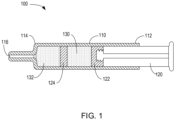
FIG. 1 is a cross-sectional view of a syringe according to non-limiting embodiments described herein; -
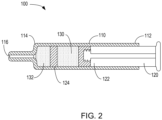
FIG. 2 is a cross-sectional view of a syringe according to non-limiting embodiments described herein; and -
FIG. 3 is a cross-sectional view of a syringe according to non-limiting embodiments described herein. - The following description is provided to enable those skilled in the art to make and use the described embodiments contemplated for carrying out the invention. Various modifications, equivalents, variations, and alternatives, however, will remain readily apparent to those skilled in the art. Any and all such modifications, variations, equivalents, and alternatives are intended to fall within the spirit and scope of the present invention.
- For purposes of the description hereinafter, the terms "upper", "lower", "right", "left", "vertical", "horizontal", "top", "bottom", "lateral", "longitudinal", and derivatives thereof shall relate to the invention as it is oriented in the drawing figures. However, it is to be understood that the invention may assume various alternative variations, except where expressly specified to the contrary. It is also to be understood that the specific devices illustrated in the attached drawings, and described in the following specification, are simply exemplary embodiments of the invention. Hence, specific dimensions and other physical characteristics related to the embodiments disclosed herein are not to be considered as limiting.
- With reference to
FIG. 1 , shown is a non-limiting embodiment of a sequential-injection syringe 100. Sequential-injection syringe 100 may be a pre-filled syringe, having abarrel 110 with aproximal end 112 anddistal end 114 and defining an interior adapted or configured to hold one or a plurality of therapeutic compositions.Barrel 110 can be formed of any suitable material. In non-limiting embodiments or aspects,barrel 110 is formed of glass or a polymer, such as a plastic.Distal end 114 ofsyringe 100 may include anopening 116, at which a needle may be arranged. While not shown,syringe 100 may include one or more safety features relating to such a needle, for example a cap assembly and/or a rigid needle shield (RNS). RNSs are known in the art, and include an inner, elastomeric portion that encases a needle, and an outer, rigid plastic portion. - With continuing reference to
FIG. 1 ,syringe 100 may include aplunger rod 120.Plunger rod 120 is arranged at proximal end ofbarrel 110, and is slidable relative thereto from a proximal-most position to a distal-most position.Plunger rod 120 may include anelastomeric stopper 122 at a distal end thereof.Syringe 100 may also include avalve stopper 124 received within interior.Valve stopper 124 may be configured such that interior ofsyringe 100 is divided into two chambers, afirst chamber 130 arranged betweenplunger stopper 122 andvalve stopper 124, and asecond chamber 132 arranged betweenvalve stopper 124 anddistal end 114 ofsyringe 100. In non-limiting embodiments,valve stopper 124 may be configured such that under a first condition, such as up to a predetermined pressure differential betweenfirst chamber 130 andsecond chamber 132, valve stopper is in a first configuration and maintains fluid isolation between the chambers. In non-limiting embodiments, under a second condition, for example a hydrolytic pressure disequilibrium between the two chambers,valve stopper 124 may assume a second configuration, and placefirst chamber 130 in fluid communication withsecond chamber 132. Suitable valve stoppers are disclosed inU.S. Patent Application Publication No. 2022/0134003 , the content of which is incorporated herein by reference in its entirety. - Stoppers, and elastomeric materials for use in the same, are known to those of skill in the art. In non-limiting embodiments or aspects, a useful stopper is formed of an elastomeric material, such as, but not limited to, natural or synthetic rubber, thermoset elastomers, thermoplastic elastomers, and liquid silicone rubber (LSR). In non-limiting embodiments or aspects, the rubber is butyl rubber (IIR), isoprene rubber (IR), butadiene rubber (BR), styrene-butadiene rubber (SBR), ethylene-propylene rubber (EPM), ethylene-propylene-diene rubber (EPDM), chlorosulphonated polyethylene (CSM), ethylene-vinyl acetate copolymer (EVA), styrene-isoprene rubber (SIR), thermoplastic elastomers, and/or natural rubbers.
- In non-limiting embodiments or aspects, the stopper can be formed of an elastomeric copolymer, including, without limitation, thermoplastic elastomers, thermoplastic vulcanizates, styrene copolymers such as styrene-butadiene (SBR or SBS) copolymers, styrene-isoprene (SIS) block polymers, or styrene-isoprene/butadiene (SIBS), in which the content of styrene in the styrene block copolymer ranges from about 10% to about 70%, and preferably from about 20% to about 50%. The elastomeric composition can include, without limitation, antioxidants and/or inorganic reinforcing agents to preserve the stability of the elastomer composition, a vulcanizing agent, a vulcanizing accelerator, a vulcanizing activator, a processing aid, a filler, etc., to maintain and improve the physical properties and heat resistance of the rubber material.
- In non-limiting embodiments or aspects,
plunger stopper 122,valve stopper 124, and/or inner facing surface ofbarrel 110 sidewall can include a coating thereon. Coatings, for example those for decreasing friction between a stopper and sidewall and/or for reducing interactions between the elastomeric material of the stopper and the medicament, for example siloxane-based coatings, are known to those of skill in the art, and are described in, for example,U.S. Patent Application Publication Nos. 2014/0221934 and2014/0110297 , the contents of which are incorporated herein by reference in their entirety. In one non-limiting aspect, the face of the valve and/or plunger stopper can be coated with a material to limit substances leaching and being extracted from the valve or plunger stopper into the concentrated pharmaceutical composition, diluent, and/or second pharmaceutical composition. - With continuing reference to
FIG. 1 , shown issyringe 100 in a pre-use configuration. In such a configuration,plunger rod 120 is in a proximal position. In non-limiting embodiments,first chamber 130 may have a first volume, andsecond chamber 132 may have a second volume. In non-limiting embodiments, the first volume and the second volume may be in a predetermined ratio. In a static condition,valve stopper 124 in first configuration maintains fluid isolation betweenfirst chamber 130 andsecond chamber 132. In non-limiting embodiments, a therapeutic composition, including an active pharmaceutical ingredient (API), is received in thesecond chamber 132, and a diluent is received withinfirst chamber 130. In other non-limiting embodiments, a therapeutic composition, including an active pharmaceutical ingredient (API), is received in thefirst chamber 130, and a diluent is received withinsecond chamber 132. In still other configurations, a second pharmaceutical composition, including a different API, may replace and/or supplement the diluent in either thefirst chamber 130 or thesecond chamber 132. The API may be any therapeutic. In non-limiting embodiments the therapeutic is mRNA-based. In non-limiting embodiments, the API is included in the therapeutic composition at a concentration of at least about 1 µg/ml, at least about 10 µg/ml, at least about 25 µg/ml, at least about 70 µg/ml, and/or at least about 100 µg/ml, all values and subranges therebetween inclusive. With regard to thefirst chamber 130, suitable diluents are known to those of skill in the art, and may include water-for-injection (WFI), saline, buffers, and/or other composition known to those of skill in the art for being safe for administration to a patient. In non-limiting embodiments, the diluent is matched to the therapeutic composition. - With reference to
FIG. 2 , shown is a use configuration ofsyringe 100.Plunger rod 120 is shown along a path of travel from a proximal positon (FIG. 1 ) as therapeutic composition is delivered throughopening 116 to a patient. In non-limiting embodiments, because a pressure difference betweenfirst chamber 130 andsecond chamber 132 does not exceed a pre-determined threshold to which valve stopper is configured,valve stopper 124 remains in a first configuration and maintains fluid isolation offirst chamber 130 fromsecond chamber 132. In non-limiting embodiments,plunger stopper 122 and/orvalve stopper 124 are configured such that valve stopper moves distally at substantially the same rate asplunger stopper 122. In non-limiting embodiments, for example based on the substantially similar movement ofplunger stopper 122 andvalve stopper 124, the predetermined ratio of first volume and second volume is maintained during at least an initial period of drug delivery. - Turning to
FIG. 3 , shown is a use configuration ofsyringe 100 following the use configuration ofFIG. 2 , and in whichplunger rod 120 has been advanced distally to a position in which therapeutic composition withinsecond chamber 132 has been delivered to a patient. In non-limiting embodiments, only a dead volume of the therapeutic composition remains insecond chamber 132. In non-limiting embodiments, asvalve stopper 124 has advanced as far distally withinbarrel 110 as possible, pressure buildup withinfirst chamber 130 results in hydrolytic pressure disequilibrium, andvalve stopper 124 switches to a second configuration, placingfirst chamber 130 in fluid communication withsecond chamber 132. In such a second configuration, diluent infirst chamber 130 may flush the dead volume of therapeutic composition remaining withinsecond chamber 132, thereby delivering any remaining volume of therapeutic composition to the patient. - Although the invention has been described in detail for the purpose of illustration based on what are currently considered to be the most practical and preferred embodiments, it is to be understood that such detail is solely for that purpose and that the invention is not limited to the disclosed embodiments, but on the contrary, is intended to cover modifications and equivalent arrangements that are within the spirit and scope of the appended claims. For example, it is to be understood that the present invention contemplates that, to the extent possible, one or more features of any embodiment can be combined with one or more features of any other embodiment.
Claims (20)
- A sequential-injection syringe, comprising:a barrel comprising a proximal end, a distal end having an opening, and a sidewall therebetween defining a syringe interior;a plunger rod at least partially received within the syringe interior and slidable relative to the barrel, the plunger rod having a proximal end and a distal end;a plunger stopper arranged at the distal end of the plunger rod;a valve stopper arranged in the syringe interior and configured to separate the syringe interior into a first chamber and a second chamber;a concentrated pharmaceutical composition received within at least one of the first chamber and the second chamber; anda diluent received within at least one of the other of the first chamber and the second chamber.
- The sequential-injection syringe of claim 1, wherein the concentrated pharmaceutical composition is received within the second chamber and the diluent is received within the first chamber.
- The sequential-injection syringe of claim 1, wherein the concentrated pharmaceutical composition is received within the first chamber and the diluent is received within the second chamber.
- The sequential-injection syringe of any of claims 1-3, wherein a concentration of the pharmaceutical composition received within the second chamber is at least 10 µg/ml, optionally at least 100 µg/ml.
- The sequential-injection syringe of any of claims 1-4, wherein the pharmaceutical composition comprises mRNA.
- The sequential-injection syringe of any of claims 1-5, wherein the diluent is water for injection or a buffer.
- The sequential-injection syringe of any of claims 1-6, wherein the barrel comprises glass or plastic.
- The sequential-injection syringe of any of claims 1-7, wherein an inner surface of the barrel is coated with a friction-reducing composition.
- The sequential-injection syringe of any of claims 1-8, wherein the valve stopper and/or the plunger stopper comprise an elastomeric material.
- The sequential-injection syringe of any of claims 1-9, wherein the valve stopper and/or the plunger stopper are coated with a friction-reducing material.
- The sequential-injection syringe of any of claims 1-10, wherein the valve stopper is configured to move simultaneously co-extensively with the plunger rod, such that a ratio of a volume of the first chamber to a volume of the second chamber remains substantially constant during an initial phase of plunger rod movement.
- The sequential-injection syringe of any of claims 1-11, wherein the valve stopper is configured such that the second chamber is not in fluid communication with the first chamber during the initial phase of plunger rod movement.
- The sequential-injection syringe of any of claims 1-12, wherein as the plunger rod reaches its distal-most position, a hydrostatic pressure disequilibrium within the syringe interior causes the second chamber to be in fluid communication with the first chamber.
- The sequential-injection syringe of any of claims 1-13, wherein the valve stopper comprises one or more reversibly-sealable openings therethrough.
- The sequential-injection syringe of any of claims 1-14, wherein causing the second chamber to be in fluid communication with the first chamber results in flushing of a dead volume of the first chamber through the opening.
- The sequential-injection syringe of any of claims 1-15, wherein the dead volume is between about 2.5 µl and about 70 µl.
- A kit comprising one or more sequential-inj ection syringes of any of claims 1-16.
- A sequential-injection syringe, comprising:a barrel comprising a proximal end, a distal end having an opening, and a sidewall therebetween defining a syringe interior;a plunger rod at least partially received within the syringe interior and slidable relative to the barrel, the plunger rod having a proximal end and a distal end;a plunger stopper arranged at the distal end of the plunger rod;a valve stopper arranged in the syringe interior and configured to separate the syringe interior into a first chamber and a second chamber;a concentrated pharmaceutical composition received within at least one of the first chamber and the second chamber; anda second pharmaceutical composition received within at least one of the other of the first chamber and the second chamber, the second pharmaceutical composition different than the concentrated pharmaceutical composition.
- The sequential-injection syringe of claim 18, wherein the concentrated pharmaceutical composition is received within the second chamber and the second pharmaceutical composition is received within the first chamber.
- The sequential-injection syringe of claim 18, wherein the concentrated pharmaceutical composition is received within the first chamber and the second pharmaceutical composition is received within the second chamber.
Priority Applications (3)
| Application Number | Priority Date | Filing Date | Title |
|---|---|---|---|
| EP23306804.8A EP4541387A1 (en) | 2023-10-16 | 2023-10-16 | Sequential-injection syringe |
| CN202480066310.5A CN122028944A (en) | 2023-10-16 | 2024-10-14 | Sequential injection syringe |
| PCT/EP2024/078867 WO2025082904A1 (en) | 2023-10-16 | 2024-10-14 | Sequential-injection syringe |
Applications Claiming Priority (1)
| Application Number | Priority Date | Filing Date | Title |
|---|---|---|---|
| EP23306804.8A EP4541387A1 (en) | 2023-10-16 | 2023-10-16 | Sequential-injection syringe |
Publications (1)
| Publication Number | Publication Date |
|---|---|
| EP4541387A1 true EP4541387A1 (en) | 2025-04-23 |
Family
ID=88600376
Family Applications (1)
| Application Number | Title | Priority Date | Filing Date |
|---|---|---|---|
| EP23306804.8A Pending EP4541387A1 (en) | 2023-10-16 | 2023-10-16 | Sequential-injection syringe |
Country Status (3)
| Country | Link |
|---|---|
| EP (1) | EP4541387A1 (en) |
| CN (1) | CN122028944A (en) |
| WO (1) | WO2025082904A1 (en) |
Citations (6)
| Publication number | Priority date | Publication date | Assignee | Title |
|---|---|---|---|---|
| US20040116871A1 (en) * | 2001-03-07 | 2004-06-17 | Patrice Vincent | Syringe for visco-elastic solutions |
| US7101354B2 (en) * | 2004-05-03 | 2006-09-05 | Infusive Technologies, Llc | Mixing syringe with and without flush |
| US20120323173A1 (en) * | 2011-04-18 | 2012-12-20 | Thorne Consulting And Intellectual Property, Llc | Medical syringe filling and valving |
| US20140110297A1 (en) | 2007-06-25 | 2014-04-24 | The Regents Of The University Of Colorado | "Medical Articles Coated With Organopolysiloxane Containing a Protein Solution" |
| US20140221934A1 (en) | 2011-09-27 | 2014-08-07 | Becton Dickinson France | Use of plasma treated silicone oil as a coating in a medical injection device |
| US20220134003A1 (en) | 2019-02-27 | 2022-05-05 | Becton Dickinson France | Valve Stopper for a Medical Injection Device and Medical Injection Device for Injecting at Least One Composition |
-
2023
- 2023-10-16 EP EP23306804.8A patent/EP4541387A1/en active Pending
-
2024
- 2024-10-14 CN CN202480066310.5A patent/CN122028944A/en active Pending
- 2024-10-14 WO PCT/EP2024/078867 patent/WO2025082904A1/en active Pending
Patent Citations (6)
| Publication number | Priority date | Publication date | Assignee | Title |
|---|---|---|---|---|
| US20040116871A1 (en) * | 2001-03-07 | 2004-06-17 | Patrice Vincent | Syringe for visco-elastic solutions |
| US7101354B2 (en) * | 2004-05-03 | 2006-09-05 | Infusive Technologies, Llc | Mixing syringe with and without flush |
| US20140110297A1 (en) | 2007-06-25 | 2014-04-24 | The Regents Of The University Of Colorado | "Medical Articles Coated With Organopolysiloxane Containing a Protein Solution" |
| US20120323173A1 (en) * | 2011-04-18 | 2012-12-20 | Thorne Consulting And Intellectual Property, Llc | Medical syringe filling and valving |
| US20140221934A1 (en) | 2011-09-27 | 2014-08-07 | Becton Dickinson France | Use of plasma treated silicone oil as a coating in a medical injection device |
| US20220134003A1 (en) | 2019-02-27 | 2022-05-05 | Becton Dickinson France | Valve Stopper for a Medical Injection Device and Medical Injection Device for Injecting at Least One Composition |
Also Published As
| Publication number | Publication date |
|---|---|
| CN122028944A (en) | 2026-05-12 |
| WO2025082904A1 (en) | 2025-04-24 |
Similar Documents
| Publication | Publication Date | Title |
|---|---|---|
| EP3656373B1 (en) | Syringe | |
| ES2856216T3 (en) | Leak-free stopper for a syringe assembly that has low breakout and holding forces | |
| US10799639B2 (en) | Syringe type medication delivery device | |
| ES2762110T3 (en) | Single use syringe with pulse reduction system | |
| JP7599832B2 (en) | Pharmaceutical container and liquid composition | |
| US20080255521A1 (en) | Prefilled syringe | |
| BR112020011830A2 (en) | devices and methods for precision dose distribution | |
| US9055992B2 (en) | Dual medicament carpule for dental syringes | |
| CA3129652A1 (en) | Valve stopper for a medical injection device and medical injection device for injecting at least one composition | |
| US11844938B2 (en) | Apparatus and methods for low-volume medicament delivery | |
| US20230226280A1 (en) | Syringe injector with a feedback mechanism | |
| KR20150023052A (en) | Medical injection device | |
| CN115397399A (en) | Stable botulinum toxin prefilled syringe dosage form with easily controlled exit velocity | |
| JP7575196B2 (en) | Pharmaceutical container and liquid composition | |
| KR20220071163A (en) | Botulinum toxin prefilled syringe formulation | |
| JP2016531697A (en) | Syringe with integral ampoule | |
| WO2025082904A1 (en) | Sequential-injection syringe | |
| US11167089B2 (en) | Reduced sputtering syringe | |
| KR20210125354A (en) | Botulinum toxin prefilled syringe formulation | |
| HK40025572A (en) | Syringe | |
| HK40025572B (en) | Syringe | |
| US20250073123A1 (en) | Medical Device Comprising Self-Lubricating Rubber Component | |
| US20230364352A1 (en) | Safety Syringe | |
| KR20210125358A (en) | Botulinum toxin prefilled syringe formulation | |
| GB2551729A (en) | Non-sputtering syringe |
Legal Events
| Date | Code | Title | Description |
|---|---|---|---|
| PUAI | Public reference made under article 153(3) epc to a published international application that has entered the european phase |
Free format text: ORIGINAL CODE: 0009012 |
|
| STAA | Information on the status of an ep patent application or granted ep patent |
Free format text: STATUS: THE APPLICATION HAS BEEN PUBLISHED |
|
| AK | Designated contracting states |
Kind code of ref document: A1 Designated state(s): AL AT BE BG CH CY CZ DE DK EE ES FI FR GB GR HR HU IE IS IT LI LT LU LV MC ME MK MT NL NO PL PT RO RS SE SI SK SM TR |
|
| STAA | Information on the status of an ep patent application or granted ep patent |
Free format text: STATUS: REQUEST FOR EXAMINATION WAS MADE |
|
| 17P | Request for examination filed |
Effective date: 20251017 |