EP4541321A1 - Femoral offset system for knee arthroplasty procedure - Google Patents
Femoral offset system for knee arthroplasty procedure Download PDFInfo
- Publication number
- EP4541321A1 EP4541321A1 EP23204449.5A EP23204449A EP4541321A1 EP 4541321 A1 EP4541321 A1 EP 4541321A1 EP 23204449 A EP23204449 A EP 23204449A EP 4541321 A1 EP4541321 A1 EP 4541321A1
- Authority
- EP
- European Patent Office
- Prior art keywords
- femur
- femoral offset
- femoral
- peg
- component
- Prior art date
- Legal status (The legal status is an assumption and is not a legal conclusion. Google has not performed a legal analysis and makes no representation as to the accuracy of the status listed.)
- Pending
Links
Images



Classifications
-
- A—HUMAN NECESSITIES
- A61—MEDICAL OR VETERINARY SCIENCE; HYGIENE
- A61F—FILTERS IMPLANTABLE INTO BLOOD VESSELS; PROSTHESES; DEVICES PROVIDING PATENCY TO, OR PREVENTING COLLAPSING OF, TUBULAR STRUCTURES OF THE BODY, e.g. STENTS; ORTHOPAEDIC, NURSING OR CONTRACEPTIVE DEVICES; FOMENTATION; TREATMENT OR PROTECTION OF EYES OR EARS; BANDAGES, DRESSINGS OR ABSORBENT PADS; FIRST-AID KITS
- A61F2/00—Filters implantable into blood vessels; Prostheses, i.e. artificial substitutes or replacements for parts of the body; Appliances for connecting them with the body; Devices providing patency to, or preventing collapsing of, tubular structures of the body, e.g. stents
- A61F2/02—Prostheses implantable into the body
- A61F2/30—Joints
- A61F2/46—Special tools for implanting artificial joints
- A61F2/4657—Measuring instruments used for implanting artificial joints
-
- A—HUMAN NECESSITIES
- A61—MEDICAL OR VETERINARY SCIENCE; HYGIENE
- A61B—DIAGNOSIS; SURGERY; IDENTIFICATION
- A61B17/00—Surgical instruments, devices or methods
- A61B17/14—Surgical saws
- A61B17/15—Guides therefor
- A61B17/154—Guides therefor for preparing bone for knee prosthesis
- A61B17/155—Cutting femur
-
- A—HUMAN NECESSITIES
- A61—MEDICAL OR VETERINARY SCIENCE; HYGIENE
- A61B—DIAGNOSIS; SURGERY; IDENTIFICATION
- A61B17/00—Surgical instruments, devices or methods
- A61B17/16—Instruments for performing osteoclasis; Drills or chisels for bones; Trepans
- A61B17/17—Guides or aligning means for drills, mills, pins or wires
- A61B17/1739—Guides or aligning means for drills, mills, pins or wires specially adapted for particular parts of the body
- A61B17/1764—Guides or aligning means for drills, mills, pins or wires specially adapted for particular parts of the body for the knee
-
- A—HUMAN NECESSITIES
- A61—MEDICAL OR VETERINARY SCIENCE; HYGIENE
- A61F—FILTERS IMPLANTABLE INTO BLOOD VESSELS; PROSTHESES; DEVICES PROVIDING PATENCY TO, OR PREVENTING COLLAPSING OF, TUBULAR STRUCTURES OF THE BODY, e.g. STENTS; ORTHOPAEDIC, NURSING OR CONTRACEPTIVE DEVICES; FOMENTATION; TREATMENT OR PROTECTION OF EYES OR EARS; BANDAGES, DRESSINGS OR ABSORBENT PADS; FIRST-AID KITS
- A61F2/00—Filters implantable into blood vessels; Prostheses, i.e. artificial substitutes or replacements for parts of the body; Appliances for connecting them with the body; Devices providing patency to, or preventing collapsing of, tubular structures of the body, e.g. stents
- A61F2/02—Prostheses implantable into the body
- A61F2/30—Joints
- A61F2/38—Joints for elbows or knees
-
- A—HUMAN NECESSITIES
- A61—MEDICAL OR VETERINARY SCIENCE; HYGIENE
- A61F—FILTERS IMPLANTABLE INTO BLOOD VESSELS; PROSTHESES; DEVICES PROVIDING PATENCY TO, OR PREVENTING COLLAPSING OF, TUBULAR STRUCTURES OF THE BODY, e.g. STENTS; ORTHOPAEDIC, NURSING OR CONTRACEPTIVE DEVICES; FOMENTATION; TREATMENT OR PROTECTION OF EYES OR EARS; BANDAGES, DRESSINGS OR ABSORBENT PADS; FIRST-AID KITS
- A61F2/00—Filters implantable into blood vessels; Prostheses, i.e. artificial substitutes or replacements for parts of the body; Appliances for connecting them with the body; Devices providing patency to, or preventing collapsing of, tubular structures of the body, e.g. stents
- A61F2/02—Prostheses implantable into the body
- A61F2/30—Joints
- A61F2/46—Special tools for implanting artificial joints
- A61F2/4684—Trial or dummy prostheses
-
- A—HUMAN NECESSITIES
- A61—MEDICAL OR VETERINARY SCIENCE; HYGIENE
- A61F—FILTERS IMPLANTABLE INTO BLOOD VESSELS; PROSTHESES; DEVICES PROVIDING PATENCY TO, OR PREVENTING COLLAPSING OF, TUBULAR STRUCTURES OF THE BODY, e.g. STENTS; ORTHOPAEDIC, NURSING OR CONTRACEPTIVE DEVICES; FOMENTATION; TREATMENT OR PROTECTION OF EYES OR EARS; BANDAGES, DRESSINGS OR ABSORBENT PADS; FIRST-AID KITS
- A61F2/00—Filters implantable into blood vessels; Prostheses, i.e. artificial substitutes or replacements for parts of the body; Appliances for connecting them with the body; Devices providing patency to, or preventing collapsing of, tubular structures of the body, e.g. stents
- A61F2/02—Prostheses implantable into the body
- A61F2/30—Joints
- A61F2/38—Joints for elbows or knees
- A61F2/3859—Femoral components
-
- A—HUMAN NECESSITIES
- A61—MEDICAL OR VETERINARY SCIENCE; HYGIENE
- A61F—FILTERS IMPLANTABLE INTO BLOOD VESSELS; PROSTHESES; DEVICES PROVIDING PATENCY TO, OR PREVENTING COLLAPSING OF, TUBULAR STRUCTURES OF THE BODY, e.g. STENTS; ORTHOPAEDIC, NURSING OR CONTRACEPTIVE DEVICES; FOMENTATION; TREATMENT OR PROTECTION OF EYES OR EARS; BANDAGES, DRESSINGS OR ABSORBENT PADS; FIRST-AID KITS
- A61F2/00—Filters implantable into blood vessels; Prostheses, i.e. artificial substitutes or replacements for parts of the body; Appliances for connecting them with the body; Devices providing patency to, or preventing collapsing of, tubular structures of the body, e.g. stents
- A61F2/02—Prostheses implantable into the body
- A61F2/30—Joints
- A61F2002/30001—Additional features of subject-matter classified in A61F2/28, A61F2/30 and subgroups thereof
- A61F2002/30316—The prosthesis having different structural features at different locations within the same prosthesis; Connections between prosthetic parts; Special structural features of bone or joint prostheses not otherwise provided for
- A61F2002/30329—Connections or couplings between prosthetic parts, e.g. between modular parts; Connecting elements
- A61F2002/30433—Connections or couplings between prosthetic parts, e.g. between modular parts; Connecting elements using additional screws, bolts, dowels, rivets or washers e.g. connecting screws
-
- A—HUMAN NECESSITIES
- A61—MEDICAL OR VETERINARY SCIENCE; HYGIENE
- A61F—FILTERS IMPLANTABLE INTO BLOOD VESSELS; PROSTHESES; DEVICES PROVIDING PATENCY TO, OR PREVENTING COLLAPSING OF, TUBULAR STRUCTURES OF THE BODY, e.g. STENTS; ORTHOPAEDIC, NURSING OR CONTRACEPTIVE DEVICES; FOMENTATION; TREATMENT OR PROTECTION OF EYES OR EARS; BANDAGES, DRESSINGS OR ABSORBENT PADS; FIRST-AID KITS
- A61F2/00—Filters implantable into blood vessels; Prostheses, i.e. artificial substitutes or replacements for parts of the body; Appliances for connecting them with the body; Devices providing patency to, or preventing collapsing of, tubular structures of the body, e.g. stents
- A61F2/02—Prostheses implantable into the body
- A61F2/30—Joints
- A61F2002/30001—Additional features of subject-matter classified in A61F2/28, A61F2/30 and subgroups thereof
- A61F2002/30316—The prosthesis having different structural features at different locations within the same prosthesis; Connections between prosthetic parts; Special structural features of bone or joint prostheses not otherwise provided for
- A61F2002/30329—Connections or couplings between prosthetic parts, e.g. between modular parts; Connecting elements
- A61F2002/30476—Connections or couplings between prosthetic parts, e.g. between modular parts; Connecting elements locked by an additional locking mechanism
- A61F2002/30492—Connections or couplings between prosthetic parts, e.g. between modular parts; Connecting elements locked by an additional locking mechanism using a locking pin
-
- A—HUMAN NECESSITIES
- A61—MEDICAL OR VETERINARY SCIENCE; HYGIENE
- A61F—FILTERS IMPLANTABLE INTO BLOOD VESSELS; PROSTHESES; DEVICES PROVIDING PATENCY TO, OR PREVENTING COLLAPSING OF, TUBULAR STRUCTURES OF THE BODY, e.g. STENTS; ORTHOPAEDIC, NURSING OR CONTRACEPTIVE DEVICES; FOMENTATION; TREATMENT OR PROTECTION OF EYES OR EARS; BANDAGES, DRESSINGS OR ABSORBENT PADS; FIRST-AID KITS
- A61F2/00—Filters implantable into blood vessels; Prostheses, i.e. artificial substitutes or replacements for parts of the body; Appliances for connecting them with the body; Devices providing patency to, or preventing collapsing of, tubular structures of the body, e.g. stents
- A61F2/02—Prostheses implantable into the body
- A61F2/30—Joints
- A61F2002/30001—Additional features of subject-matter classified in A61F2/28, A61F2/30 and subgroups thereof
- A61F2002/30316—The prosthesis having different structural features at different locations within the same prosthesis; Connections between prosthetic parts; Special structural features of bone or joint prostheses not otherwise provided for
- A61F2002/30329—Connections or couplings between prosthetic parts, e.g. between modular parts; Connecting elements
- A61F2002/30476—Connections or couplings between prosthetic parts, e.g. between modular parts; Connecting elements locked by an additional locking mechanism
- A61F2002/305—Snap connection
-
- A—HUMAN NECESSITIES
- A61—MEDICAL OR VETERINARY SCIENCE; HYGIENE
- A61F—FILTERS IMPLANTABLE INTO BLOOD VESSELS; PROSTHESES; DEVICES PROVIDING PATENCY TO, OR PREVENTING COLLAPSING OF, TUBULAR STRUCTURES OF THE BODY, e.g. STENTS; ORTHOPAEDIC, NURSING OR CONTRACEPTIVE DEVICES; FOMENTATION; TREATMENT OR PROTECTION OF EYES OR EARS; BANDAGES, DRESSINGS OR ABSORBENT PADS; FIRST-AID KITS
- A61F2/00—Filters implantable into blood vessels; Prostheses, i.e. artificial substitutes or replacements for parts of the body; Appliances for connecting them with the body; Devices providing patency to, or preventing collapsing of, tubular structures of the body, e.g. stents
- A61F2/02—Prostheses implantable into the body
- A61F2/30—Joints
- A61F2002/30001—Additional features of subject-matter classified in A61F2/28, A61F2/30 and subgroups thereof
- A61F2002/30316—The prosthesis having different structural features at different locations within the same prosthesis; Connections between prosthetic parts; Special structural features of bone or joint prostheses not otherwise provided for
- A61F2002/30329—Connections or couplings between prosthetic parts, e.g. between modular parts; Connecting elements
- A61F2002/30476—Connections or couplings between prosthetic parts, e.g. between modular parts; Connecting elements locked by an additional locking mechanism
- A61F2002/30505—Connections or couplings between prosthetic parts, e.g. between modular parts; Connecting elements locked by an additional locking mechanism spring biased
-
- A—HUMAN NECESSITIES
- A61—MEDICAL OR VETERINARY SCIENCE; HYGIENE
- A61F—FILTERS IMPLANTABLE INTO BLOOD VESSELS; PROSTHESES; DEVICES PROVIDING PATENCY TO, OR PREVENTING COLLAPSING OF, TUBULAR STRUCTURES OF THE BODY, e.g. STENTS; ORTHOPAEDIC, NURSING OR CONTRACEPTIVE DEVICES; FOMENTATION; TREATMENT OR PROTECTION OF EYES OR EARS; BANDAGES, DRESSINGS OR ABSORBENT PADS; FIRST-AID KITS
- A61F2/00—Filters implantable into blood vessels; Prostheses, i.e. artificial substitutes or replacements for parts of the body; Appliances for connecting them with the body; Devices providing patency to, or preventing collapsing of, tubular structures of the body, e.g. stents
- A61F2/02—Prostheses implantable into the body
- A61F2/30—Joints
- A61F2002/30001—Additional features of subject-matter classified in A61F2/28, A61F2/30 and subgroups thereof
- A61F2002/30316—The prosthesis having different structural features at different locations within the same prosthesis; Connections between prosthetic parts; Special structural features of bone or joint prostheses not otherwise provided for
- A61F2002/30329—Connections or couplings between prosthetic parts, e.g. between modular parts; Connecting elements
- A61F2002/30518—Connections or couplings between prosthetic parts, e.g. between modular parts; Connecting elements with possibility of relative movement between the prosthetic parts
-
- A—HUMAN NECESSITIES
- A61—MEDICAL OR VETERINARY SCIENCE; HYGIENE
- A61F—FILTERS IMPLANTABLE INTO BLOOD VESSELS; PROSTHESES; DEVICES PROVIDING PATENCY TO, OR PREVENTING COLLAPSING OF, TUBULAR STRUCTURES OF THE BODY, e.g. STENTS; ORTHOPAEDIC, NURSING OR CONTRACEPTIVE DEVICES; FOMENTATION; TREATMENT OR PROTECTION OF EYES OR EARS; BANDAGES, DRESSINGS OR ABSORBENT PADS; FIRST-AID KITS
- A61F2/00—Filters implantable into blood vessels; Prostheses, i.e. artificial substitutes or replacements for parts of the body; Appliances for connecting them with the body; Devices providing patency to, or preventing collapsing of, tubular structures of the body, e.g. stents
- A61F2/02—Prostheses implantable into the body
- A61F2/30—Joints
- A61F2002/30001—Additional features of subject-matter classified in A61F2/28, A61F2/30 and subgroups thereof
- A61F2002/30316—The prosthesis having different structural features at different locations within the same prosthesis; Connections between prosthetic parts; Special structural features of bone or joint prostheses not otherwise provided for
- A61F2002/30535—Special structural features of bone or joint prostheses not otherwise provided for
- A61F2002/30604—Special structural features of bone or joint prostheses not otherwise provided for modular
-
- A—HUMAN NECESSITIES
- A61—MEDICAL OR VETERINARY SCIENCE; HYGIENE
- A61F—FILTERS IMPLANTABLE INTO BLOOD VESSELS; PROSTHESES; DEVICES PROVIDING PATENCY TO, OR PREVENTING COLLAPSING OF, TUBULAR STRUCTURES OF THE BODY, e.g. STENTS; ORTHOPAEDIC, NURSING OR CONTRACEPTIVE DEVICES; FOMENTATION; TREATMENT OR PROTECTION OF EYES OR EARS; BANDAGES, DRESSINGS OR ABSORBENT PADS; FIRST-AID KITS
- A61F2/00—Filters implantable into blood vessels; Prostheses, i.e. artificial substitutes or replacements for parts of the body; Appliances for connecting them with the body; Devices providing patency to, or preventing collapsing of, tubular structures of the body, e.g. stents
- A61F2/02—Prostheses implantable into the body
- A61F2/30—Joints
- A61F2002/30001—Additional features of subject-matter classified in A61F2/28, A61F2/30 and subgroups thereof
- A61F2002/30316—The prosthesis having different structural features at different locations within the same prosthesis; Connections between prosthetic parts; Special structural features of bone or joint prostheses not otherwise provided for
- A61F2002/30535—Special structural features of bone or joint prostheses not otherwise provided for
- A61F2002/30604—Special structural features of bone or joint prostheses not otherwise provided for modular
- A61F2002/30607—Kits of prosthetic parts to be assembled in various combinations for forming different prostheses
-
- A—HUMAN NECESSITIES
- A61—MEDICAL OR VETERINARY SCIENCE; HYGIENE
- A61F—FILTERS IMPLANTABLE INTO BLOOD VESSELS; PROSTHESES; DEVICES PROVIDING PATENCY TO, OR PREVENTING COLLAPSING OF, TUBULAR STRUCTURES OF THE BODY, e.g. STENTS; ORTHOPAEDIC, NURSING OR CONTRACEPTIVE DEVICES; FOMENTATION; TREATMENT OR PROTECTION OF EYES OR EARS; BANDAGES, DRESSINGS OR ABSORBENT PADS; FIRST-AID KITS
- A61F2/00—Filters implantable into blood vessels; Prostheses, i.e. artificial substitutes or replacements for parts of the body; Appliances for connecting them with the body; Devices providing patency to, or preventing collapsing of, tubular structures of the body, e.g. stents
- A61F2/02—Prostheses implantable into the body
- A61F2/30—Joints
- A61F2002/30001—Additional features of subject-matter classified in A61F2/28, A61F2/30 and subgroups thereof
- A61F2002/30316—The prosthesis having different structural features at different locations within the same prosthesis; Connections between prosthetic parts; Special structural features of bone or joint prostheses not otherwise provided for
- A61F2002/30535—Special structural features of bone or joint prostheses not otherwise provided for
- A61F2002/30604—Special structural features of bone or joint prostheses not otherwise provided for modular
- A61F2002/30616—Sets comprising a plurality of prosthetic parts of different sizes or orientations
-
- A—HUMAN NECESSITIES
- A61—MEDICAL OR VETERINARY SCIENCE; HYGIENE
- A61F—FILTERS IMPLANTABLE INTO BLOOD VESSELS; PROSTHESES; DEVICES PROVIDING PATENCY TO, OR PREVENTING COLLAPSING OF, TUBULAR STRUCTURES OF THE BODY, e.g. STENTS; ORTHOPAEDIC, NURSING OR CONTRACEPTIVE DEVICES; FOMENTATION; TREATMENT OR PROTECTION OF EYES OR EARS; BANDAGES, DRESSINGS OR ABSORBENT PADS; FIRST-AID KITS
- A61F2/00—Filters implantable into blood vessels; Prostheses, i.e. artificial substitutes or replacements for parts of the body; Appliances for connecting them with the body; Devices providing patency to, or preventing collapsing of, tubular structures of the body, e.g. stents
- A61F2/02—Prostheses implantable into the body
- A61F2/30—Joints
- A61F2002/30001—Additional features of subject-matter classified in A61F2/28, A61F2/30 and subgroups thereof
- A61F2002/30316—The prosthesis having different structural features at different locations within the same prosthesis; Connections between prosthetic parts; Special structural features of bone or joint prostheses not otherwise provided for
- A61F2002/30535—Special structural features of bone or joint prostheses not otherwise provided for
- A61F2002/30617—Visible markings for adjusting, locating or measuring
-
- A—HUMAN NECESSITIES
- A61—MEDICAL OR VETERINARY SCIENCE; HYGIENE
- A61F—FILTERS IMPLANTABLE INTO BLOOD VESSELS; PROSTHESES; DEVICES PROVIDING PATENCY TO, OR PREVENTING COLLAPSING OF, TUBULAR STRUCTURES OF THE BODY, e.g. STENTS; ORTHOPAEDIC, NURSING OR CONTRACEPTIVE DEVICES; FOMENTATION; TREATMENT OR PROTECTION OF EYES OR EARS; BANDAGES, DRESSINGS OR ABSORBENT PADS; FIRST-AID KITS
- A61F2/00—Filters implantable into blood vessels; Prostheses, i.e. artificial substitutes or replacements for parts of the body; Appliances for connecting them with the body; Devices providing patency to, or preventing collapsing of, tubular structures of the body, e.g. stents
- A61F2/02—Prostheses implantable into the body
- A61F2/30—Joints
- A61F2002/30001—Additional features of subject-matter classified in A61F2/28, A61F2/30 and subgroups thereof
- A61F2002/30667—Features concerning an interaction with the environment or a particular use of the prosthesis
- A61F2002/3069—Revision endoprostheses
-
- A—HUMAN NECESSITIES
- A61—MEDICAL OR VETERINARY SCIENCE; HYGIENE
- A61F—FILTERS IMPLANTABLE INTO BLOOD VESSELS; PROSTHESES; DEVICES PROVIDING PATENCY TO, OR PREVENTING COLLAPSING OF, TUBULAR STRUCTURES OF THE BODY, e.g. STENTS; ORTHOPAEDIC, NURSING OR CONTRACEPTIVE DEVICES; FOMENTATION; TREATMENT OR PROTECTION OF EYES OR EARS; BANDAGES, DRESSINGS OR ABSORBENT PADS; FIRST-AID KITS
- A61F2/00—Filters implantable into blood vessels; Prostheses, i.e. artificial substitutes or replacements for parts of the body; Appliances for connecting them with the body; Devices providing patency to, or preventing collapsing of, tubular structures of the body, e.g. stents
- A61F2/02—Prostheses implantable into the body
- A61F2/30—Joints
- A61F2/46—Special tools for implanting artificial joints
- A61F2/4657—Measuring instruments used for implanting artificial joints
- A61F2002/4658—Measuring instruments used for implanting artificial joints for measuring dimensions, e.g. length
Definitions
- the disclosure refers to a femoral offset system for use in a knee arthroplasty procedure, in particular a revision procedure comprising a femoral offset instrument and to such a femoral offset instrument.
- a femoral offset instrument allows to determine and/or measure and or check a femoral offset of a femoral implant on a distal portion of a femur bone. Such instruments are known from prior art.
- the purpose of the present disclosure is to provide a femoral offset system, which allows comfortable handling thereby simplifying the workflow when using the femoral offset system in a knee arthroplasty procedure.
- a first aspect refers to a femoral offset system for use in a knee arthroplasty procedure, in particular a revision procedure.
- the femoral offset system comprises a femur component being connectable to a distal portion of a femur, and a femoral offset instrument being connectable to the femur component.
- the femoral offset instrument comprises a femur support, the femur support being adapted to be connected to the femur component via a connection mechanism.
- connection mechanism for connecting the femoral offset instrument to the femur component comprises: a fixed peg and a movable peg connected to the femoral offset instrument, a manually operable operating element, which allows retracting the movable peg by applying a manual force against a tension force, and receiving pockets for the fixed peg and the movable peg arranged on the femur component.
- the movable peg is retracted by applying a manual force against a tension force, the femoral offset instrument and the femur component are aligned to each other accordingly, the manual force is released and the movable peg snaps into the respective receiving pocket due to the acting tension force.
- connection mechanism allows to connect the femoral offset instrument to the femur component in a fixedly, statically, non-rotationally and undisplaceable but releasable manner.
- the proposed solution requires only manually pressing operating element and thereby retracting the movable peg by applying a manual force against a tension force and releasing the operating element.
- the proposed solution avoids the use of screws or other connection variants, which require more effort.
- the fixed peg and the movable peg of the femoral offset instrument are arranged on the femur support medially and laterally with regard to the marking element.
- the fixed peg is fixedly connected to the femur support.
- the movable peg is arranged on the femur support in a movable manner.
- the movable peg and the operating element are fixedly connected.
- the movable peg and the operating element might be fixedly connected via firmly bonding or other suitable connection manners.
- the movable peg and the manually operable operating element might be realized as an integrally component.
- the femur support comprises at least one guiding groove
- the operating element comprises a corresponding protrusion arranged in said guiding groove, wherein the femur support and the operating element are adapted such that the protrusion can slide in the guiding groove.
- the two guiding grooves and the two protrusions may each be arranged distally and proximally relative to each other.
- the operating element is secured to the femur support, for example via a suitable securing mechanism.
- the operating element and the femur support are movable relative to each other to a given extent.
- the securing might be done via a pin or two pins located in corresponding recesses of the femur support, the two pins preventing the protrusion(s) from falling out of the guiding groove(s).
- the femur support comprises at least one femur attachment member for fixedly connecting the femur support to the femur component and the femur component comprises at least one corresponding recess for receiving the one femur attachment member.
- the femur attachment member extends medially or laterally from the femur support.
- the femur support comprises two femur attachment members, the two femur attachment members being medially and laterally arranged with regard to the marking element, wherein the fixed peg is fixedly connected to one of the attachment member and the other one of the attachment members receives the operating element.
- the medially arranged femur attachment member extends medially from the femur support.
- the laterally arranged femur attachment member extends laterally from the femur support.
- the fixed peg is fixedly connected to the medially arranged femur attachment member
- the fixed peg extends medially therefrom.
- the fixed peg is fixedly connected to the laterally arranged femur attachment member, the fixed peg extends laterally therefrom.
- the tension force acts in the lateral direction, and the movable peg connected to the operating element extends laterally from the laterally arranged attachment member in case no manual force is applied against the tension force.
- the tension force acts in the medial direction, and the movable peg connected to the operating element extends medially from the medially arranged attachment member in case no manual force is applied against the tension force.
- the femur component might comprise two corresponding recesses for receiving the two femur attachment members, the recesses being medially and laterally arranged with regard to each other, wherein the receiving pockets for receiving the fixed pin and the movable pin extend from the recess in the medial and lateral directions, respectively.
- the femur component is a trial femur implant and/or a femoral cutting guide.
- the femur component, in particular the trial femur implant or the femoral cutting guide is, temporarily connectable during knee arthroplasty procedure.
- the marking element is an offset eyeballing.
- the marking element allows eyeballing of the femoral offset.
- the marking element allows to determine and/or measure and/or check a femoral offset.
- the offset bushing is a separate component, which is connectable to the femoral offset instrument.
- the offset bushing is rotatable around a rotational axis.
- the marking element and the offset bushing may allow guiding of a drill for preparing the cone of the femur using a drill.
- a second aspect of the disclosure refers to a femoral offset instrument for a femoral offset system according to the described embodiments, the femoral offset instrument comprising a femur support, the femur support being adapted to be connected to the femur component via a connection mechanism, wherein the connection mechanism comprises: a fixed peg and a movable peg connected to the femoral offset instrument, a manually operable operating element, which allows retracting the movable peg by applying a manual force against a tension force.
- the femoral offset instrument might be designed as described above with regard to the femoral offset system.
- a third aspect of the disclosure refers to a femur component for a femoral offset system according to the described embodiments, the femur component being connectable to a distal portion of a femur and comprising receiving pockets for a fixed peg and a movable peg of the femoral offset instrument.
- the femur component might be designed as described above with regard to the femoral offset system.
- a fourth aspect of the disclosure refers a set of femoral offset systems and/or femoral offset instruments and/or femur components, comprising at least two femoral offset systems according to the described embodiments and/or at least two femur components according to the described embodiments and/or at least two femur components according to the described embodiments, wherein the at least two femoral offset systems and/or the at least two femur components and/or the two femur components differ in at least a size or a form.
- FIG 1 schematically depicts a femoral offset instrument 10.
- the femoral offset instrument 10 might be used together with a femur component 12 as depicted for example in figures 3 and 5 in femoral offset system 14 as depicted for example in figures 4 and 6 .
- the femoral offset system 14 is designed for use in a knee arthroplasty procedure, in particular a revision procedure.
- the femoral offset instrument 10 is right or left specific instrument with regard to a right or left femur. This means the femoral offset instrument 10 comprises a right or left orientation, which is indicated for example by an "R” or “L” displayed on the instrument. The following examples refer to a left specific instrument.
- a distal, proximal, medial, lateral direction with regard to a left femur is indicated in the figures by respective arrows D/P, M/L.
- the femur component 12 is temporarily connectable to a distal portion of a femur (not displayed).
- the femoral offset instrument 10 is connectable to the femur component 12, see for example figures 4 and 6 via a connection mechanism.
- the connection mechanism allows to connect the femoral offset instrument 10 to the femur component 12 in a fixedly, statically, non-rotationally and undisplaceable but releasable manner.
- the design and functionality is described in the following in an exemplary manner with regard to the figures.
- the femoral offset instrument 10 comprises a femur support 16.
- the femur support 16 is adapted to be connected to the femur component 12 via the connection mechanism.
- the femoral offset instrument 10 comprises a marking element 18, which provides marking of the offset.
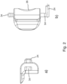
- Fig. 1 a depicts the femoral offset instrument 10 in an unmounted state and in an exploded view.
- the femur support 16 comprises two femur attachment members 20 for fixedly connecting the femur support 16 to the femur component 12.
- a medially arranged femur attachment member 20M extends medially from the femur support 16.
- a laterally arranged femur attachment member 20L extends laterally from the femur support 16.
- Each attachment member 20 may have a flat end 44 combined with two rounded ends 46, making it easier to position the attachment member 20 and offering greater precision when positioning.
- the femoral offset instrument 10 comprises a fixed peg 22 and a movable peg 24, both connected to the femoral offset instrument 10.
- the fixed peg 22 is fixedly connected to the femur support 16.
- the fixed peg 22 is connected to the medially arranged femur attachment member 20M.
- the movable peg 24 is arranged on the femur support 16 in a movable manner.
- the fixed peg 22 may have a flat 48 end combined with two rounded ends 50, making it easier to position the fixed peg 22 and offering greater precision when positioning.
- the movable peg 24 is fixedly connected to an operating element 26 of the femoral offset instrument 10.
- the movable peg 24 and the operating element 26 are realized as an integrally component.
- the laterally arranged femur attachment member 20L receives the operating element 26.
- the fixed peg 22 and the movable peg 24 of the femoral offset instrument 10 are arranged on the femur support 16 medially and laterally with regard to the marking element 18.
- the operating element 26 is manually operable, which allows retracting the movable peg 24 by applying a manual force against a tension force.
- the tension force is provided by spring 30.
- the tension force acts in the lateral direction.
- the movable peg connected to the operating element 26 extends laterally from the laterally arranged attachment member 20L in case no manual force is applied against the tension force, see fig. 1 .
- the movable peg can be retracted in the medial directing by applying a manual force on the operating element 26 against a tension force.
- the femur support 16 comprises two guiding grooves 32.
- the operating element 26 comprises two corresponding protrusions 34, wherein one protrusion is formed by the movable peg 24.
- the protrusions 34 are arranged in a respective guiding groove 32 each, wherein the femur support 16 and the operating element 26 are adapted such that the protrusions 34 might slide in the guiding grooves 32.
- the operating element 26 When operating the operating element 26 by applying a manual force or releasing the manual force, the operating element moves in the respective direction in a translatory manner guided by the guiding grooves 32.
- the two guiding grooves 32 and the two protrusions 34 are arranged distally and proximally relative to each other.
- the operating element 26 is secured to the femur support 16, for example via a suitable securing mechanism. Despite the securing, the operating element 26 and the femur support 16 are movable relative to each other to a given extent. The securing is done via two pins 36 located in corresponding recesses 38 of the femur support 16, the two pins 36 preventing the protrusions 34 from dropping out of the guiding grooves 32.
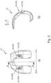
- connection mechanism comprises two recesses 40 arranged on the femur component 12 for receiving corresponding femur attachment members 20.
- the recesses 40M, 40L are medially and laterally arranged with regard to each other.
- the femur component 12 comprises further two receiving pockets 42, one for the fixed peg 22 and one for the movable peg 24.
- the receiving pocket 42M for receiving the fixed pin 22 extends from the medially arranged recess 40M in the medial direction and the receiving pocket 42L for receiving the movable pin 24 extends from the laterally arranged recess 40 L in the lateral direction.
- the femoral offset instrument and the femur component are positioned accordingly to each other, by positioning the medially arranged attachment member 20M in the medially arranged recess 40M such that the fixed peg 22 engages with the receiving pocket 42M.
- the movable peg 24 is retracted by applying a manual force on the operating element 26 against the tension force, such that the movable peg 24 is retracted in the medial direction.
- the femoral offset instrument 10 and the femur component 12 are aligned to each other accordingly by positioning the laterally arranged attachment member 20L in the recess 40L, and the manual force is released and the movable peg 24 snaps in the lateral direction into the respective receiving pocket 42 L due to the acting tension force.
- the proposed solution requires only manually pressing the operating element 26 and thereby retracting the movable peg 24 by applying a manual force against the tension force and releasing the operating element 26.
- the proposed solution avoids the use of screws or other connection variants, which require more effort.
- the femur component is a trial femur implant, see fig. 3 and 4 .
- the femur component is a femoral cutting guide, see fig. 5 and 6 .
- the marking element 18 is an offset eyeballing, which allows eyeballing of the femoral offset.
- the offset eyeballing helps the surgeon to determine the femoral offset to be used for positioning of an implant.
- the marking element 18 allows determine and/or measure and/or check the correct femoral offset.
- the offset bushing is a separate component, which is connectable to the femoral offset instrument.
- the offset bushing is rotatable around a rotational axis.
- the marking element 18 and the offset bushing may allow guiding of a drill for preparing the cone of the femur using a drill.
Landscapes
- Health & Medical Sciences (AREA)
- Orthopedic Medicine & Surgery (AREA)
- Life Sciences & Earth Sciences (AREA)
- Transplantation (AREA)
- Oral & Maxillofacial Surgery (AREA)
- General Health & Medical Sciences (AREA)
- Engineering & Computer Science (AREA)
- Biomedical Technology (AREA)
- Heart & Thoracic Surgery (AREA)
- Veterinary Medicine (AREA)
- Public Health (AREA)
- Animal Behavior & Ethology (AREA)
- Surgery (AREA)
- Physical Education & Sports Medicine (AREA)
- Vascular Medicine (AREA)
- Cardiology (AREA)
- Nuclear Medicine, Radiotherapy & Molecular Imaging (AREA)
- Dentistry (AREA)
- Medical Informatics (AREA)
- Molecular Biology (AREA)
- Biophysics (AREA)
- Surgical Instruments (AREA)
- Prostheses (AREA)
Abstract
The disclosure refers to a femoral offset system (14) for use in a knee arthroplasty procedure, in particular a revision procedure, comprising a femur component (12) being connectable to a distal portion of a femur, and an femoral offset instrument (10) being connectable to the femur component (12), wherein the femoral offset instrument (10) comprises a femur support (16), the femur support (16) being adapted to be connected to the femur component (12) via a connection mechanism.
Description
- The disclosure refers to a femoral offset system for use in a knee arthroplasty procedure, in particular a revision procedure comprising a femoral offset instrument and to such a femoral offset instrument. A femoral offset instrument allows to determine and/or measure and or check a femoral offset of a femoral implant on a distal portion of a femur bone. Such instruments are known from prior art.
- The purpose of the present disclosure is to provide a femoral offset system, which allows comfortable handling thereby simplifying the workflow when using the femoral offset system in a knee arthroplasty procedure.
- A first aspect refers to a femoral offset system for use in a knee arthroplasty procedure, in particular a revision procedure. The femoral offset system comprises a femur component being connectable to a distal portion of a femur, and a femoral offset instrument being connectable to the femur component. The femoral offset instrument comprises a femur support, the femur support being adapted to be connected to the femur component via a connection mechanism. The connection mechanism for connecting the femoral offset instrument to the femur component comprises: a fixed peg and a movable peg connected to the femoral offset instrument, a manually operable operating element, which allows retracting the movable peg by applying a manual force against a tension force, and receiving pockets for the fixed peg and the movable peg arranged on the femur component. For connecting the femoral offset instrument to the femur component, the movable peg is retracted by applying a manual force against a tension force, the femoral offset instrument and the femur component are aligned to each other accordingly, the manual force is released and the movable peg snaps into the respective receiving pocket due to the acting tension force.
- The connection mechanism allows to connect the femoral offset instrument to the femur component in a fixedly, statically, non-rotationally and undisplaceable but releasable manner.
- The proposed solution requires only manually pressing operating element and thereby retracting the movable peg by applying a manual force against a tension force and releasing the operating element. In particular, the proposed solution avoids the use of screws or other connection variants, which require more effort.
- According to an embodiment, the fixed peg and the movable peg of the femoral offset instrument are arranged on the femur support medially and laterally with regard to the marking element. The fixed peg is fixedly connected to the femur support. The movable peg is arranged on the femur support in a movable manner.
- Advantageously, the movable peg and the operating element are fixedly connected. The movable peg and the operating element might be fixedly connected via firmly bonding or other suitable connection manners. The movable peg and the manually operable operating element might be realized as an integrally component.
- In some exemplary embodiments, the femur support comprises at least one guiding groove, and the operating element comprises a corresponding protrusion arranged in said guiding groove, wherein the femur support and the operating element are adapted such that the protrusion can slide in the guiding groove. When operating the operating element by applying a manual force or releasing the manual force, the operating element moves in the respective direction in a translatory manner guided by the guiding groove.
- The two guiding grooves and the two protrusions may each be arranged distally and proximally relative to each other.
- Advantageously, the operating element is secured to the femur support, for example via a suitable securing mechanism. Despite the securing, the operating element and the femur support are movable relative to each other to a given extent. The securing might be done via a pin or two pins located in corresponding recesses of the femur support, the two pins preventing the protrusion(s) from falling out of the guiding groove(s).
- According to further preferred embodiments, the femur support comprises at least one femur attachment member for fixedly connecting the femur support to the femur component and the femur component comprises at least one corresponding recess for receiving the one femur attachment member. For example, the femur attachment member extends medially or laterally from the femur support.
- Advantageously, the femur support comprises two femur attachment members, the two femur attachment members being medially and laterally arranged with regard to the marking element, wherein the fixed peg is fixedly connected to one of the attachment member and the other one of the attachment members receives the operating element. For example, the medially arranged femur attachment member extends medially from the femur support. For example, the laterally arranged femur attachment member extends laterally from the femur support. In case the fixed peg is fixedly connected to the medially arranged femur attachment member, the fixed peg extends medially therefrom. In case the fixed peg is fixedly connected to the laterally arranged femur attachment member, the fixed peg extends laterally therefrom.
- In case the laterally arranged attachment member receives the operating element, the tension force acts in the lateral direction, and the movable peg connected to the operating element extends laterally from the laterally arranged attachment member in case no manual force is applied against the tension force.
- In case the medially arranged attachment member receives the operating element, the tension force acts in the medial direction, and the movable peg connected to the operating element extends medially from the medially arranged attachment member in case no manual force is applied against the tension force.
- The femur component might comprise two corresponding recesses for receiving the two femur attachment members, the recesses being medially and laterally arranged with regard to each other, wherein the receiving pockets for receiving the fixed pin and the movable pin extend from the recess in the medial and lateral directions, respectively.
- According to an example, the femur component is a trial femur implant and/or a femoral cutting guide. The femur component, in particular the trial femur implant or the femoral cutting guide is, temporarily connectable during knee arthroplasty procedure.
- According to an example, the marking element is an offset eyeballing. The marking element allows eyeballing of the femoral offset. Combined with an offset bushing, the marking element allows to determine and/or measure and/or check a femoral offset. The offset bushing is a separate component, which is connectable to the femoral offset instrument. Held by the femur support, the offset bushing is rotatable around a rotational axis. According to a further example, the marking element and the offset bushing may allow guiding of a drill for preparing the cone of the femur using a drill.
- A second aspect of the disclosure refers to a femoral offset instrument for a femoral offset system according to the described embodiments, the femoral offset instrument comprising a femur support, the femur support being adapted to be connected to the femur component via a connection mechanism, wherein the connection mechanism comprises:
a fixed peg and a movable peg connected to the femoral offset instrument, a manually operable operating element, which allows retracting the movable peg by applying a manual force against a tension force. - According to further embodiments, the femoral offset instrument might be designed as described above with regard to the femoral offset system.
- A third aspect of the disclosure refers to a femur component for a femoral offset system according to the described embodiments, the femur component being connectable to a distal portion of a femur and comprising receiving pockets for a fixed peg and a movable peg of the femoral offset instrument.
- According to further embodiments, the femur component might be designed as described above with regard to the femoral offset system.
- A fourth aspect of the disclosure refers a set of femoral offset systems and/or femoral offset instruments and/or femur components, comprising at least two femoral offset systems according to the described embodiments and/or at least two femur components according to the described embodiments and/or at least two femur components according to the described embodiments, wherein the at least two femoral offset systems and/or the at least two femur components and/or the two femur components differ in at least a size or a form.
- Further advantageous embodiments are derivable from the following description of Exemplary embodiments with reference to the drawings. In the drawings:
- Fig. 1
- schematically depicts a femoral offset instrument in different views (a) and b) and c));
- Fig. 2
- schematically depicts a part of a femoral offset instrument in different views (a) and b));
- Fig. 3
- schematically depicts a femur component, according to an embodiment in different views (a) and b));
- Fig. 4
- schematically depicts a femoral offset system according to an embodiment in different views (a) and b));
- Fig. 5
- schematically depicts a femur component, according to another embodiment in different views (a) and b));
- Fig. 6
- schematically depicts a femoral offset system according to another.
-
Figure 1 schematically depicts afemoral offset instrument 10. Thefemoral offset instrument 10 might be used together with afemur component 12 as depicted for example infigures 3 and5 infemoral offset system 14 as depicted for example infigures 4 and6 . - The femoral offset
system 14 is designed for use in a knee arthroplasty procedure, in particular a revision procedure. - The femoral offset
instrument 10 is right or left specific instrument with regard to a right or left femur. This means the femoral offsetinstrument 10 comprises a right or left orientation, which is indicated for example by an "R" or "L" displayed on the instrument. The following examples refer to a left specific instrument. - A distal, proximal, medial, lateral direction with regard to a left femur is indicated in the figures by respective arrows D/P, M/L.
- The
femur component 12 is temporarily connectable to a distal portion of a femur (not displayed). - The femoral offset
instrument 10 is connectable to thefemur component 12, see for examplefigures 4 and6 via a connection mechanism. The connection mechanism allows to connect the femoral offsetinstrument 10 to thefemur component 12 in a fixedly, statically, non-rotationally and undisplaceable but releasable manner. The design and functionality is described in the following in an exemplary manner with regard to the figures. - The femoral offset
instrument 10 comprises afemur support 16. Thefemur support 16 is adapted to be connected to thefemur component 12 via the connection mechanism. According to the examples, the femoral offsetinstrument 10 comprises a markingelement 18, which provides marking of the offset. -
Fig. 1 a) depicts the femoral offsetinstrument 10 in an unmounted state and in an exploded view.Fig. 1 b) and c) depict the femoral offsetinstrument 10 in a mounted state. - In the example, the
femur support 16 comprises two femur attachment members 20 for fixedly connecting thefemur support 16 to thefemur component 12. A medially arrangedfemur attachment member 20M extends medially from thefemur support 16. A laterally arrangedfemur attachment member 20L extends laterally from thefemur support 16. - Each attachment member 20 may have a
flat end 44 combined with two rounded ends 46, making it easier to position the attachment member 20 and offering greater precision when positioning. - The femoral offset
instrument 10 comprises a fixed peg 22 and amovable peg 24, both connected to the femoral offsetinstrument 10. The fixed peg 22 is fixedly connected to thefemur support 16. In the example, the fixed peg 22 is connected to the medially arrangedfemur attachment member 20M. Themovable peg 24 is arranged on thefemur support 16 in a movable manner. - The fixed peg 22 may have a flat 48 end combined with two rounded ends 50, making it easier to position the fixed peg 22 and offering greater precision when positioning.
- In the example, the
movable peg 24 is fixedly connected to anoperating element 26 of the femoral offsetinstrument 10. According to the example, themovable peg 24 and the operatingelement 26 are realized as an integrally component. In the example, the laterally arrangedfemur attachment member 20L receives the operatingelement 26. - Therefore, the fixed peg 22 and the
movable peg 24 of the femoral offsetinstrument 10 are arranged on thefemur support 16 medially and laterally with regard to the markingelement 18. - The operating
element 26 is manually operable, which allows retracting themovable peg 24 by applying a manual force against a tension force. In the example, the tension force is provided byspring 30. According to the example, the tension force acts in the lateral direction. The movable peg connected to theoperating element 26 extends laterally from the laterally arrangedattachment member 20L in case no manual force is applied against the tension force, seefig. 1 . The movable peg can be retracted in the medial directing by applying a manual force on the operatingelement 26 against a tension force. - In the example, the
femur support 16 comprises two guidinggrooves 32. The operatingelement 26 comprises two correspondingprotrusions 34, wherein one protrusion is formed by themovable peg 24. Theprotrusions 34 are arranged in arespective guiding groove 32 each, wherein thefemur support 16 and the operatingelement 26 are adapted such that theprotrusions 34 might slide in the guidinggrooves 32. When operating the operatingelement 26 by applying a manual force or releasing the manual force, the operating element moves in the respective direction in a translatory manner guided by the guidinggrooves 32. In the example, the two guidinggrooves 32 and the twoprotrusions 34 are arranged distally and proximally relative to each other. - In the example, the operating
element 26 is secured to thefemur support 16, for example via a suitable securing mechanism. Despite the securing, the operatingelement 26 and thefemur support 16 are movable relative to each other to a given extent. The securing is done via twopins 36 located in correspondingrecesses 38 of thefemur support 16, the twopins 36 preventing theprotrusions 34 from dropping out of the guidinggrooves 32. - With regard to the
femur component 12, the connection mechanism comprises two recesses 40 arranged on thefemur component 12 for receiving corresponding femur attachment members 20. The recesses 40M, 40L are medially and laterally arranged with regard to each other. - The
femur component 12 comprises further two receiving pockets 42, one for the fixed peg 22 and one for themovable peg 24. The receiving pocket 42M for receiving the fixed pin 22 extends from the medially arranged recess 40M in the medial direction and the receiving pocket 42L for receiving themovable pin 24 extends from the laterally arranged recess 40 L in the lateral direction. - For connecting the femoral offset instrument to the femur component, the following steps might be performed:
The femoral offset instrument and the femur component are positioned accordingly to each other, by positioning the medially arrangedattachment member 20M in the medially arranged recess 40M such that the fixed peg 22 engages with the receiving pocket 42M. - The
movable peg 24 is retracted by applying a manual force on the operatingelement 26 against the tension force, such that themovable peg 24 is retracted in the medial direction. - The femoral offset
instrument 10 and thefemur component 12 are aligned to each other accordingly by positioning the laterally arrangedattachment member 20L in the recess 40L, and the manual force is released and themovable peg 24 snaps in the lateral direction into the respective receiving pocket 42 L due to the acting tension force. - The proposed solution requires only manually pressing the
operating element 26 and thereby retracting themovable peg 24 by applying a manual force against the tension force and releasing the operatingelement 26. In particular, the proposed solution avoids the use of screws or other connection variants, which require more effort. - According to an example, the femur component is a trial femur implant, see
fig. 3 and4 . - According to a further example, the femur component is a femoral cutting guide, see
fig. 5 and6 . - According to the examples, the marking
element 18 is an offset eyeballing, which allows eyeballing of the femoral offset. During knee arthroplasty procedure, the offset eyeballing helps the surgeon to determine the femoral offset to be used for positioning of an implant. Combined with an offset bushing, which is not displayed in the figures, the markingelement 18 allows determine and/or measure and/or check the correct femoral offset. The offset bushing is a separate component, which is connectable to the femoral offset instrument. Held by thefemur support 16, the offset bushing is rotatable around a rotational axis. According to a further example, the markingelement 18 and the offset bushing may allow guiding of a drill for preparing the cone of the femur using a drill.
Claims (14)
- Femoral offset system (14) for use in a knee arthroplasty procedure, in particular a revision procedure, comprising a femur component (12) being connectable to a distal portion of a femur, and an femoral offset instrument (10) being connectable to the femur component (12), wherein the femoral offset instrument (10) comprises a femur support (16), the femur support (16) being adapted to be connected to the femur component (12) via a connection mechanism, wherein the connection mechanism comprises:
a fixed peg (22) and a movable peg (24) connected to the femoral offset instrument (10), a manually operable operating element (26), which allows retracting the movable peg (24) by applying a manual force against a tension force, and receiving pockets (42, 42M, 42L) for the fixed peg (22) and the movable peg (24) arranged on the femur component (12). - Femoral offset system (14) according to claim 1,
wherein the fixed peg (22) and the movable peg (24) of the femoral offset instrument (10) are arranged on the femur support (16) medially and laterally with regard to a marking element (18) of the femoral offset instrument (10). - Femoral offset system (14) according to any of the claims 1 or 2, wherein the movable peg (24) and the operating element (26) are fixedly connected, in particular the movable peg (24) and the operating element (26) are realized as an integrally component.
- Femoral offset system (14) according to any of the preceding claims, wherein the femur support (16) comprises at least one guiding groove (32), and the operating element (26) comprises a corresponding protrusion (34) arranged in said guiding groove (32), wherein the femur support (16) and the operating element (26) are adapted such that the protrusion (34) is adapted to slide in the guiding groove (32).
- Femoral offset system (14) according to claim 4,
wherein the movable peg (24) forms a protrusion (34) arranged in said guiding groove (32). - Femoral offset system (14) according to any of the preceding claims, wherein the operating element (26) is secured to the femur support (16).
- Femoral offset system (14) according to any of the preceding claims, wherein the femur support (16) comprises at least one femur attachment member (20) for fixedly connecting the femur support (16) to the femur component (12) and the femur component (12) comprises at least one corresponding recess (40) for receiving the one femur attachment member (20).
- Femoral offset system (14) according to claim 7,
wherein the femur support comprises two femur attachment members (20, 20M, 20L), the two femur attachment members being medially and laterally arranged with regard to the marking element (18), wherein the fixed peg (22) is fixedly connected to one of the attachment members (20M) and the other one of the attachment members (20L) receives the operating element (26). - Femoral offset system (14) according to claim 8,
wherein the femur component (12) comprises two corresponding recesses (40, 40M, 40L) for receiving the two femur attachment members (20, 20M, 20L), the recesses (40, 40M, 40L) being medially and laterally arranged with regard to each other, wherein the receiving pockets (42, 42M, 42L) for receiving the fixed pin (22) and the movable pin (24) extend from the recesses (40, 40M, 40L) in the medial and lateral directions, respectively. - Femoral offset system (14) according to any of the preceding claims, wherein the femur component (12) is a trial femur implant and/or a femoral cutting guide.
- Femoral offset system (14) according to any of the preceding claims, wherein the marking element (18) is an offset eyeballing.
- Femoral offset instrument (10) for a femoral offset system (14) according to any of the preceding claims, the femoral offset instrument (10) comprising a femur support (16), the femur support (16) being adapted to be connected to the femur component (12) via a connection mechanism, wherein the connection mechanism comprises:
a fixed peg (22) and a movable peg (24) connected to the femoral offset instrument (10), a manually operable operating element (26), which allows retracting the movable peg (22) by applying a manual force against a tension force. - Femur component (12) for a femoral offset system (14) according to any of the preceding claims 1 to 11, the femur component (12) being connectable to a distal portion of a femur and comprising receiving pockets (42, 42M, 42L) for a fixed peg (22) and a movable peg (24) of a femoral offset instrument (10).
- A set of femoral offset systems (14) and/or femoral offset instruments (10) and/or femur components (12), comprising at least two femoral offset systems (14) according to any of the claims 1 to 11 and/or at least two femur components (12) according to claim 12 and/or at least two femur components (12) according to claim 13, wherein the at least two femoral offset systems (14) and/or the at least two femur components (12) and/or the two femur components (12) differ in at least a size or a form.
Priority Applications (3)
| Application Number | Priority Date | Filing Date | Title |
|---|---|---|---|
| EP23204449.5A EP4541321A1 (en) | 2023-10-18 | 2023-10-18 | Femoral offset system for knee arthroplasty procedure |
| US18/915,702 US20250127633A1 (en) | 2023-10-18 | 2024-10-15 | Femoral offset system for knee arthroplasty procedure |
| JP2024182059A JP2025069940A (en) | 2023-10-18 | 2024-10-17 | Femoral Offset System in Knee Arthroplasty |
Applications Claiming Priority (1)
| Application Number | Priority Date | Filing Date | Title |
|---|---|---|---|
| EP23204449.5A EP4541321A1 (en) | 2023-10-18 | 2023-10-18 | Femoral offset system for knee arthroplasty procedure |
Publications (1)
| Publication Number | Publication Date |
|---|---|
| EP4541321A1 true EP4541321A1 (en) | 2025-04-23 |
Family
ID=88417393
Family Applications (1)
| Application Number | Title | Priority Date | Filing Date |
|---|---|---|---|
| EP23204449.5A Pending EP4541321A1 (en) | 2023-10-18 | 2023-10-18 | Femoral offset system for knee arthroplasty procedure |
Country Status (3)
| Country | Link |
|---|---|
| US (1) | US20250127633A1 (en) |
| EP (1) | EP4541321A1 (en) |
| JP (1) | JP2025069940A (en) |
Citations (6)
| Publication number | Priority date | Publication date | Assignee | Title |
|---|---|---|---|---|
| US5735856A (en) * | 1997-01-31 | 1998-04-07 | Johnson & Johnson Professional, Inc. | Orthopedic cutting guide and bushing |
| US20090125114A1 (en) * | 2007-10-10 | 2009-05-14 | Biomet Manufacturing Corp. | Knee joint prosthesis system and method for implantation |
| US20140276836A1 (en) * | 2013-03-15 | 2014-09-18 | Rebecca L. Chaney | Method of surgically preparing a patient's femur |
| US20170333212A1 (en) * | 2016-05-18 | 2017-11-23 | Depuy Ireland Unlimited Company | Orthopaedic instrument system for surgically-preparing a patient's femur |
| US20170340458A1 (en) * | 2011-06-06 | 2017-11-30 | Biomet Manufacturing, Llc | Method and apparatus for implanting a knee prosthesis |
| EP3967277A1 (en) * | 2020-09-10 | 2022-03-16 | Aesculap AG | Femoral stem offset adjustment system |
-
2023
- 2023-10-18 EP EP23204449.5A patent/EP4541321A1/en active Pending
-
2024
- 2024-10-15 US US18/915,702 patent/US20250127633A1/en active Pending
- 2024-10-17 JP JP2024182059A patent/JP2025069940A/en active Pending
Patent Citations (6)
| Publication number | Priority date | Publication date | Assignee | Title |
|---|---|---|---|---|
| US5735856A (en) * | 1997-01-31 | 1998-04-07 | Johnson & Johnson Professional, Inc. | Orthopedic cutting guide and bushing |
| US20090125114A1 (en) * | 2007-10-10 | 2009-05-14 | Biomet Manufacturing Corp. | Knee joint prosthesis system and method for implantation |
| US20170340458A1 (en) * | 2011-06-06 | 2017-11-30 | Biomet Manufacturing, Llc | Method and apparatus for implanting a knee prosthesis |
| US20140276836A1 (en) * | 2013-03-15 | 2014-09-18 | Rebecca L. Chaney | Method of surgically preparing a patient's femur |
| US20170333212A1 (en) * | 2016-05-18 | 2017-11-23 | Depuy Ireland Unlimited Company | Orthopaedic instrument system for surgically-preparing a patient's femur |
| EP3967277A1 (en) * | 2020-09-10 | 2022-03-16 | Aesculap AG | Femoral stem offset adjustment system |
Also Published As
| Publication number | Publication date |
|---|---|
| JP2025069940A (en) | 2025-05-01 |
| US20250127633A1 (en) | 2025-04-24 |
Similar Documents
| Publication | Publication Date | Title |
|---|---|---|
| US5658293A (en) | Guide platform associated with intramedullary rod | |
| US5569263A (en) | Adjustable provisional articulating device | |
| EP0761172B1 (en) | Apparatus for correction of spaces between bone resection planes for knee prostheses | |
| US5562674A (en) | Intramedullary rod with guide member locator | |
| ES2201090T3 (en) | FEMORAL AUXILIARY INSTRUMENTATION FOR THE IMPLEMENTATION OF A UNICOMPARTIMENTAL PROTECTION OF THE KNEE. | |
| AU2001262308B2 (en) | Instruments used for inserting a hip cup | |
| US7878989B2 (en) | Knee prostheses | |
| EP1550420B1 (en) | Joint prosthesis with adjustable head | |
| EP1013231A3 (en) | Epicondylar axis alignment-femoral positioning drill guide | |
| CN101883540A (en) | Modular neck for orthopaedic devices | |
| EP2640282B1 (en) | Surgical instrument system, surgical alignment guide and surgical rod | |
| DE10358926B4 (en) | Resektionsschnittlehre | |
| KR20190022975A (en) | Smart surgical instruments for artificial joint replacement | |
| US9119635B2 (en) | Surgical cutting guide, surgical alignment guide and surgical instrument system | |
| EP4541321A1 (en) | Femoral offset system for knee arthroplasty procedure | |
| US11071639B2 (en) | Brace and insertion-fitting member used therefore | |
| US12402892B2 (en) | Surgical instrument | |
| JP2024015981A (en) | Surgical instruments and surgical instrument systems | |
| CN109152578A (en) | Surgical equipment for surgery on human knee | |
| US20250114104A1 (en) | Patella impaction device and patella preparation set | |
| US7959639B1 (en) | Trialing system and method utilizing offset | |
| JP2025069940A5 (en) | ||
| CN114052874A (en) | Intramedullary nail sight and skeletal treatment system including the same | |
| EP4210638B1 (en) | Femoral stem offset adjustment system | |
| CN112367940A (en) | Clearance gauge and unit capable of confirming flexion clearance before femoral rear end resection |
Legal Events
| Date | Code | Title | Description |
|---|---|---|---|
| PUAI | Public reference made under article 153(3) epc to a published international application that has entered the european phase |
Free format text: ORIGINAL CODE: 0009012 |
|
| STAA | Information on the status of an ep patent application or granted ep patent |
Free format text: STATUS: THE APPLICATION HAS BEEN PUBLISHED |
|
| AK | Designated contracting states |
Kind code of ref document: A1 Designated state(s): AL AT BE BG CH CY CZ DE DK EE ES FI FR GB GR HR HU IE IS IT LI LT LU LV MC ME MK MT NL NO PL PT RO RS SE SI SK SM TR |
|
| STAA | Information on the status of an ep patent application or granted ep patent |
Free format text: STATUS: REQUEST FOR EXAMINATION WAS MADE |
|
| 17P | Request for examination filed |
Effective date: 20251010 |