EP4541296A1 - Patella holding device - Google Patents
Patella holding device Download PDFInfo
- Publication number
- EP4541296A1 EP4541296A1 EP23203902.4A EP23203902A EP4541296A1 EP 4541296 A1 EP4541296 A1 EP 4541296A1 EP 23203902 A EP23203902 A EP 23203902A EP 4541296 A1 EP4541296 A1 EP 4541296A1
- Authority
- EP
- European Patent Office
- Prior art keywords
- patella
- holding device
- chain
- holding
- links
- Prior art date
- Legal status (The legal status is an assumption and is not a legal conclusion. Google has not performed a legal analysis and makes no representation as to the accuracy of the status listed.)
- Granted
Links
Images

Classifications
-
- A—HUMAN NECESSITIES
- A61—MEDICAL OR VETERINARY SCIENCE; HYGIENE
- A61B—DIAGNOSIS; SURGERY; IDENTIFICATION
- A61B17/00—Surgical instruments, devices or methods
- A61B17/14—Surgical saws
- A61B17/15—Guides therefor
- A61B17/154—Guides therefor for preparing bone for knee prosthesis
- A61B17/158—Cutting patella
-
- A—HUMAN NECESSITIES
- A61—MEDICAL OR VETERINARY SCIENCE; HYGIENE
- A61B—DIAGNOSIS; SURGERY; IDENTIFICATION
- A61B17/00—Surgical instruments, devices or methods
- A61B17/02—Surgical instruments, devices or methods for holding wounds open, e.g. retractors; Tractors
- A61B17/025—Joint distractors
-
- A—HUMAN NECESSITIES
- A61—MEDICAL OR VETERINARY SCIENCE; HYGIENE
- A61B—DIAGNOSIS; SURGERY; IDENTIFICATION
- A61B17/00—Surgical instruments, devices or methods
- A61B17/56—Surgical instruments or methods for treatment of bones or joints; Devices specially adapted therefor
- A61B17/58—Surgical instruments or methods for treatment of bones or joints; Devices specially adapted therefor for osteosynthesis, e.g. bone plates, screws or setting implements
- A61B17/88—Osteosynthesis instruments; Methods or means for implanting or extracting internal or external fixation devices
- A61B17/8866—Osteosynthesis instruments; Methods or means for implanting or extracting internal or external fixation devices for gripping or pushing bones, e.g. approximators
-
- A—HUMAN NECESSITIES
- A61—MEDICAL OR VETERINARY SCIENCE; HYGIENE
- A61B—DIAGNOSIS; SURGERY; IDENTIFICATION
- A61B17/00—Surgical instruments, devices or methods
- A61B2017/0042—Surgical instruments, devices or methods with special provisions for gripping
-
- A—HUMAN NECESSITIES
- A61—MEDICAL OR VETERINARY SCIENCE; HYGIENE
- A61B—DIAGNOSIS; SURGERY; IDENTIFICATION
- A61B17/00—Surgical instruments, devices or methods
- A61B2017/0042—Surgical instruments, devices or methods with special provisions for gripping
- A61B2017/00438—Surgical instruments, devices or methods with special provisions for gripping connectable to a finger
-
- A—HUMAN NECESSITIES
- A61—MEDICAL OR VETERINARY SCIENCE; HYGIENE
- A61B—DIAGNOSIS; SURGERY; IDENTIFICATION
- A61B17/00—Surgical instruments, devices or methods
- A61B17/02—Surgical instruments, devices or methods for holding wounds open, e.g. retractors; Tractors
- A61B17/025—Joint distractors
- A61B2017/0268—Joint distractors for the knee
Definitions
- the invention relates to a patella holding device for holding a patella in a holding plane, according to US 2006/0161165 A1 .
- a patella As a part of a total knee replacement or total knee arthroplasty ("TKA") surgery, the posterior portion of a patella may be resected for implanting with a patellar knee component.
- the step of resecting the patella requires the use of a patella holding device for retaining or holding the patella during cutting.
- US 2006/0161165 A1 proposes to provide a pincer-like structure with two mutually movable handle parts, one handle part being connected to a first clamping section engaging the skin / subcutaneous tissues overlying the anterior of a patella and the other handle part being connected to a second clamping section engaging the posterior of a patella, thus providing a clamping action along an antero-posterior axis of the patella.
- One object of the present invention is to provide a patella holding device which allows for a reliable holding of a patella and for a comfortable handling by a surgeon.
- the patella holding device comprises two gripping elements which are connected to each other via a chain.
- the chain comprises chain links, wherein adjacent chain links are movable relative to each other about a rotation axis which is perpendicular to the holding plane.
- the chain elements provide a flexible structure for surrounding a holding zone of a patella. This flexibility ensures a reliable fit of the patella holding device and the patella which is independent of the size and shape of the patella. At the same time, the chain elements provide for a connection of the two gripping elements allowing for a comfortable handling by a surgeon.
- the holding plane is parallel or coincides with a plane defined by the medio-lateral axis and the proximal-distal axis of the patella.
- the holding plane is parallel to or coincides with a resection plane of the patella.
- the chain elements surrounding the holding zone of the patella are arranged within the holding plane and can be positioned such that the two gripping elements are arranged adjacent to each other.
- the gripping elements can be located at any angular position within the holding plane.
- the gripping elements can be arranged on a proximal, a lateral, a distal or a medial side of a patella and in any angular intermediate position, in accordance with the preference of a surgeon.
- a surgeon can use the patella holding device in a first orientation with respect to the holding plane and in a reverse orientation with respect to the holding plane.
- the chain comprises at least 8 pivot axes, preferably at least 12 rotation axes, in particular at least 16 pivot axes. A higher number of pivot axes will allow for a snug fit of the chain along the circumference of a holding zone of the patella.
- the chain comprises at most 20 pivot axes, limiting the number of parts to be assembled during production and the number of parts to be cleaned after use.
- the chain comprises chain links which are configured as outer links and chain links which are configured as inner links, wherein the outer links and the inner links are arranged in an alternate manner, thus providing a stable and space saving structure.
- the chain links have first outer surfaces which together define a support plane for supporting a resection tool.
- a resection tool can be a saw blade which is supported by the outer surfaces.
- the resection tool has a width which is great enough for the resection tool to be supported by at least two first outer surfaces at the same time, for example by at least two first outer surfaces of two adjacent outer chain links.
- At least some of the chain links have second outer surfaces which together define a second support plane for supporting a resection tool, the second outer surfaces being parallel to the first outer surfaces.
- a support plane for a resection tool can be provided independent of the first surfaces or the second surfaces being arranged at the level of a resection plane (in other words: a support plane is provided in a first orientation and in a reverse orientation of the patella holding device).
- the chain links comprise one protrusion or at least one protrusion which is arranged within the holding plane and configured to engage with the patella.
- the protrusions are arranged at inner links of the chain.
- the at least one protrusion provides an anchoring element or fixing element and may for example have a sharp corner, such as a tooth or a hook.
- a first gripping element is configured to be manipulated by a thumb of a hand of a surgeon and in that a second gripping element is configured to be manipulated by an index finger, in particular of the same hand of the surgeon.
- a surgeon may use his right or left hand in accordance with his preference.
- the two gripping elements have an identical shape and/or size.
- the gripping elements may be ring-shaped and/or trough-shaped.
- the two gripping elements have an identical shape and/or size.
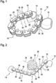
- a patella holding device 10 comprises two trough-shaped gripping elements 12 and 14.
- Each of the gripping elements may be manipulated by placing the top of a thumb or the top of an index finger of a surgeon into the trough.
- a surgeon may use the thumb and an index finger of the same hand.
- the gripping elements 12 and 14 are connected to each other by means of a chain 16.
- the chain 16 comprises outer chain links 18 and inner chain links 20 which are arranged in an alternate manner.
- the chain comprises 10 outer chain links 18 and 9 inner chain links 20.
- each of the gripping elements 12 and 14 is connected to an outer chain link 18, preferably in a non-movable manner.
- Adjacent links 18 and 20 are connected to and movable with respect to each other by means of chain pins 22, each chain pin 22 providing a rotational axis 24 around which adjacent chain links 18 and 20 can rotate or swivel within a holding plane 26 of the patella holding device 10.
- Fig. 2 illustrates an initial holding action of the patella holding device 10 within the holding plane 26 which is defined by a medio-lateral axis 28 and a proximal-distal axis 30 of a patella 32.
- the proximal-distal axis 30 is oriented in parallel with the main orientation of a patellar tendon (not shown in the drawings).
- the inner chain links 20 have a width as seen in a direction parallel to the rotation axes 24 which is smaller than the width of the outer chain links 18.
- the inner chain links 20 are each provided with one tooth-shaped protrusion 34 which is configured to engage with an engaging zone along the circumference of the patella 32.
- each outer chain links 18 comprises two plates or tabs 36, 38 which are spaced from another and overlap and adjacent inner chain link 18, see Fig. 2 .
- the tabs 36 of the outer chain links 18 each have a first outer surface 40, the plurality of outer surfaces 38 defining a first support plane 42 (schematically illustrated in Fig. 4 ).
- the tabs 38 of the outer chain links 18 each have a second outer surface 44, the plurality of outer surfaces 44 defining a second support plane 46 (schematically illustrated in Fig. 4 ).
- the support planes 42, 46 allow the support and guidance of a resection tool 48, for example a saw blade, see Fig. 4 , wherein the resection tool 48 is supported by the first support plane 42.
- a surgeon may place the chain 16 and its chain links 18, 20 within the holding plane 26 and around the circumference of the patella 32, see Fig. 3 .
- the two gripping elements 18, 20 may be positioned at any angular position within the clamping plane 34 (360 degrees of freedom).
- the patella holding device 10 may also be used in a reverse configuration in which the gripping elements 18, 20 face into an opposite direction and in which the resection tool 48 would be supported by the second support plane 46.
Landscapes
- Health & Medical Sciences (AREA)
- Surgery (AREA)
- Life Sciences & Earth Sciences (AREA)
- Medical Informatics (AREA)
- Animal Behavior & Ethology (AREA)
- Engineering & Computer Science (AREA)
- Biomedical Technology (AREA)
- Heart & Thoracic Surgery (AREA)
- Veterinary Medicine (AREA)
- Molecular Biology (AREA)
- Nuclear Medicine, Radiotherapy & Molecular Imaging (AREA)
- General Health & Medical Sciences (AREA)
- Public Health (AREA)
- Orthopedic Medicine & Surgery (AREA)
- Physical Education & Sports Medicine (AREA)
- Transplantation (AREA)
- Dentistry (AREA)
- Oral & Maxillofacial Surgery (AREA)
- Surgical Instruments (AREA)
Abstract
Description
- The invention relates to a patella holding device for holding a patella in a holding plane, according to
US 2006/0161165 A1 . - As a part of a total knee replacement or total knee arthroplasty ("TKA") surgery, the posterior portion of a patella may be resected for implanting with a patellar knee component. The step of resecting the patella requires the use of a patella holding device for retaining or holding the patella during cutting.
US 2006/0161165 A1 proposes to provide a pincer-like structure with two mutually movable handle parts, one handle part being connected to a first clamping section engaging the skin / subcutaneous tissues overlying the anterior of a patella and the other handle part being connected to a second clamping section engaging the posterior of a patella, thus providing a clamping action along an antero-posterior axis of the patella. - One object of the present invention is to provide a patella holding device which allows for a reliable holding of a patella and for a comfortable handling by a surgeon.
- This object is solved by the patella holding device with the features of claim 1. Preferred embodiments are defined in the dependent claims.
- According to the invention, the patella holding device comprises two gripping elements which are connected to each other via a chain. The chain comprises chain links, wherein adjacent chain links are movable relative to each other about a rotation axis which is perpendicular to the holding plane.
- The chain elements provide a flexible structure for surrounding a holding zone of a patella. This flexibility ensures a reliable fit of the patella holding device and the patella which is independent of the size and shape of the patella. At the same time, the chain elements provide for a connection of the two gripping elements allowing for a comfortable handling by a surgeon.
- According to a preferred embodiment, the holding plane is parallel or coincides with a plane defined by the medio-lateral axis and the proximal-distal axis of the patella.
- In particular, the holding plane is parallel to or coincides with a resection plane of the patella. The chain elements surrounding the holding zone of the patella are arranged within the holding plane and can be positioned such that the two gripping elements are arranged adjacent to each other. The gripping elements can be located at any angular position within the holding plane. For example, the gripping elements can be arranged on a proximal, a lateral, a distal or a medial side of a patella and in any angular intermediate position, in accordance with the preference of a surgeon. In addition, a surgeon can use the patella holding device in a first orientation with respect to the holding plane and in a reverse orientation with respect to the holding plane.
- In an embodiment, the chain comprises at least 8 pivot axes, preferably at least 12 rotation axes, in particular at least 16 pivot axes. A higher number of pivot axes will allow for a snug fit of the chain along the circumference of a holding zone of the patella.
- In one embodiment, the chain comprises at most 20 pivot axes, limiting the number of parts to be assembled during production and the number of parts to be cleaned after use.
- In one embodiment, the chain comprises chain links which are configured as outer links and chain links which are configured as inner links, wherein the outer links and the inner links are arranged in an alternate manner, thus providing a stable and space saving structure.
- According to a preferred embodiment, at least some of the chain links have first outer surfaces which together define a support plane for supporting a resection tool. Such a resection tool can be a saw blade which is supported by the outer surfaces. Preferably, the resection tool has a width which is great enough for the resection tool to be supported by at least two first outer surfaces at the same time, for example by at least two first outer surfaces of two adjacent outer chain links.
- According to a further preferred embodiment, at least some of the chain links have second outer surfaces which together define a second support plane for supporting a resection tool, the second outer surfaces being parallel to the first outer surfaces. In this way, a support plane for a resection tool can be provided independent of the first surfaces or the second surfaces being arranged at the level of a resection plane (in other words: a support plane is provided in a first orientation and in a reverse orientation of the patella holding device).
- To improve a holding effect of the patella holding device, at least some of the chain links comprise one protrusion or at least one protrusion which is arranged within the holding plane and configured to engage with the patella. For example, the protrusions are arranged at inner links of the chain. The at least one protrusion provides an anchoring element or fixing element and may for example have a sharp corner, such as a tooth or a hook.
- According to a preferred embodiment, a first gripping element is configured to be manipulated by a thumb of a hand of a surgeon and in that a second gripping element is configured to be manipulated by an index finger, in particular of the same hand of the surgeon. A surgeon may use his right or left hand in accordance with his preference. In a preferred embodiment, the two gripping elements have an identical shape and/or size.
- To provide a comfortable handling, the gripping elements may be ring-shaped and/or trough-shaped. In a preferred embodiment, the two gripping elements have an identical shape and/or size.
- Further features and advantages are the subject of the following description and of the diagrammatic illustration of embodiments.
- In the drawings:
- Figure 1
- shows a perspective view of one embodiment of a patella holding device;
- Figure 2
- shows a perspective view of an initial engagement of the holding device with a patella;
- Figure 3
- shows a perspective view of a complete engagement of the holding device with the patella; and
- Figure 4
- shows a perspective view of the configuration according to
Fig. 3 and of a resection tool. - According to the drawings, a
patella holding device 10 comprises two trough-shaped gripping elements - The
gripping elements chain 16. Thechain 16 comprisesouter chain links 18 andinner chain links 20 which are arranged in an alternate manner. For example, the chain comprises 10outer chain links 18 and 9inner chain links 20. For example, each of thegripping elements outer chain link 18, preferably in a non-movable manner. -
Adjacent links chain pins 22, eachchain pin 22 providing arotational axis 24 around whichadjacent chain links holding plane 26 of thepatella holding device 10. -
Fig. 2 illustrates an initial holding action of thepatella holding device 10 within theholding plane 26 which is defined by a medio-lateral axis 28 and a proximal-distal axis 30 of apatella 32. The proximal-distal axis 30 is oriented in parallel with the main orientation of a patellar tendon (not shown in the drawings). - The
inner chain links 20 have a width as seen in a direction parallel to therotation axes 24 which is smaller than the width of theouter chain links 18. - Preferably, the
inner chain links 20 are each provided with one tooth-shaped protrusion 34 which is configured to engage with an engaging zone along the circumference of thepatella 32. - Preferably, each
outer chain links 18 comprises two plates ortabs inner chain link 18, seeFig. 2 . - The
tabs 36 of theouter chain links 18 each have a firstouter surface 40, the plurality ofouter surfaces 38 defining a first support plane 42 (schematically illustrated inFig. 4 ). - The
tabs 38 of theouter chain links 18 each have a secondouter surface 44, the plurality ofouter surfaces 44 defining a second support plane 46 (schematically illustrated inFig. 4 ). - The
support planes resection tool 48, for example a saw blade, seeFig. 4 , wherein theresection tool 48 is supported by thefirst support plane 42. - In order to hold the patella 32 a surgeon may place the
chain 16 and itschain links holding plane 26 and around the circumference of thepatella 32, seeFig. 3 . The twogripping elements - The
patella holding device 10 may also be used in a reverse configuration in which thegripping elements resection tool 48 would be supported by thesecond support plane 46.
Claims (10)
- Patella holding device (10) for holding a patella (32) in a holding plane (26), characterized in that the patella holding device (10) comprises two gripping elements (12, 14) which are connected to each other via a chain (16) which comprises chain links (18, 20), wherein adjacent chain links (18, 20) are movable relative to each other about a rotation axis (24) which is perpendicular to the holding plane (26).
- Patella holding device (10) according to claim 1, characterized in that the holding plane (26) is parallel or coincides with a plane defined by the medio-lateral axis (30) and the proximal-distal axis (28) of the patella (32).
- Patella holding device (10) according to one of the preceding claims, characterized in that the chain (16) comprises at least 8 pivot axes (24), preferably at least 12 rotation axes (24), in particular at least 16 pivot axes (24).
- Patella holding device (10) according to one of the preceding claims, characterized in that the chain (16) comprises at most 20 pivot axes (24).
- Patella holding device (10) according to one of the preceding claims, characterized in that the chain (16) comprises chain links (18) which are configured as outer links and chain links (20) which are configured as inner links, wherein the outer links and the inner links are arranged in an alternate manner.
- Patella holding device (10) according to one of the preceding claims, characterized in that at least some of the chain links (18) have first outer surfaces (40) which together define a support plane (42) for supporting a resection tool (48).
- Patella holding device (10) according to claim 6, characterized in that at least some of the chain links (18) have second outer surfaces (44) which together define a second support plane (46) for supporting a resection tool, the second outer surfaces (46) being parallel to the first outer surfaces (40).
- Patella holding device (10) according to one of the preceding claims, characterized in that at least some of the chain links (20) comprise one protrusion (34) or at least one protrusion (34) which is arranged within the holding plane (26) and configured to engage with the patella (32).
- Patella holding device (10) according to one of the preceding claims, characterized in that a first gripping element (12) is configured to be manipulated by a thumb of a hand of a surgeon and in that a second gripping element (14) is configured to be manipulated by an index finger, in particular of the same hand of the surgeon.
- Patella holding device (10) according to one of the preceding claims, characterized in that the gripping elements (12, 14) are ring-shaped and/or trough-shaped.
Priority Applications (3)
| Application Number | Priority Date | Filing Date | Title |
|---|---|---|---|
| EP23203902.4A EP4541296B1 (en) | 2023-10-16 | 2023-10-16 | Patella holding device |
| JP2024179358A JP2025069091A (en) | 2023-10-16 | 2024-10-11 | Patella holding device |
| US18/914,465 US20250120686A1 (en) | 2023-10-16 | 2024-10-14 | Patella holding device |
Applications Claiming Priority (1)
| Application Number | Priority Date | Filing Date | Title |
|---|---|---|---|
| EP23203902.4A EP4541296B1 (en) | 2023-10-16 | 2023-10-16 | Patella holding device |
Publications (2)
| Publication Number | Publication Date |
|---|---|
| EP4541296A1 true EP4541296A1 (en) | 2025-04-23 |
| EP4541296B1 EP4541296B1 (en) | 2026-03-25 |
Family
ID=88417569
Family Applications (1)
| Application Number | Title | Priority Date | Filing Date |
|---|---|---|---|
| EP23203902.4A Active EP4541296B1 (en) | 2023-10-16 | 2023-10-16 | Patella holding device |
Country Status (3)
| Country | Link |
|---|---|
| US (1) | US20250120686A1 (en) |
| EP (1) | EP4541296B1 (en) |
| JP (1) | JP2025069091A (en) |
Citations (3)
| Publication number | Priority date | Publication date | Assignee | Title |
|---|---|---|---|---|
| US20060161165A1 (en) | 2002-05-10 | 2006-07-20 | Swanson Todd V | Patellar cutting guide |
| US20120101505A1 (en) * | 2010-10-26 | 2012-04-26 | Zimmer, Inc. | Patellar resection instrument with variable depth guide |
| CN112370145A (en) * | 2020-10-13 | 2021-02-19 | 皖南医学院第一附属医院(皖南医学院弋矶山医院) | Accurate-positioning reduction fixing forceps for traumatic orthopedics department |
Family Cites Families (1)
| Publication number | Priority date | Publication date | Assignee | Title |
|---|---|---|---|---|
| US2921489A (en) * | 1957-03-18 | 1960-01-19 | Standard Oil Co | Chain-type pipe wrench |
-
2023
- 2023-10-16 EP EP23203902.4A patent/EP4541296B1/en active Active
-
2024
- 2024-10-11 JP JP2024179358A patent/JP2025069091A/en active Pending
- 2024-10-14 US US18/914,465 patent/US20250120686A1/en active Pending
Patent Citations (3)
| Publication number | Priority date | Publication date | Assignee | Title |
|---|---|---|---|---|
| US20060161165A1 (en) | 2002-05-10 | 2006-07-20 | Swanson Todd V | Patellar cutting guide |
| US20120101505A1 (en) * | 2010-10-26 | 2012-04-26 | Zimmer, Inc. | Patellar resection instrument with variable depth guide |
| CN112370145A (en) * | 2020-10-13 | 2021-02-19 | 皖南医学院第一附属医院(皖南医学院弋矶山医院) | Accurate-positioning reduction fixing forceps for traumatic orthopedics department |
Also Published As
| Publication number | Publication date |
|---|---|
| EP4541296B1 (en) | 2026-03-25 |
| JP2025069091A (en) | 2025-04-30 |
| US20250120686A1 (en) | 2025-04-17 |
Similar Documents
| Publication | Publication Date | Title |
|---|---|---|
| US11998219B2 (en) | Surgical saw blade for wedge osteotomies | |
| US5913858A (en) | Instrumentation for implanting a spherical prosthesis | |
| JP4027798B2 (en) | Interphalangeal joint replacement device | |
| US5308350A (en) | Femoral distractor for use in knee surgery | |
| US8313530B2 (en) | Total knee arthroplasty system | |
| ES2638523T3 (en) | Prosthetic device with dual multi-axis support assembly | |
| ES2439715T3 (en) | Patella resection guide and assembly | |
| US4198712A (en) | Scaphoid implant | |
| US20060155294A1 (en) | Tibial/femoral recutter with paddle | |
| JP6092220B2 (en) | Surgical instruments | |
| JP2013071012A (en) | Patella drilling system | |
| US11974924B2 (en) | Modular patella trials | |
| US20120191199A1 (en) | Method and apparatus for distal radioulnar joint (druj) arthroplasty | |
| US9522007B2 (en) | Orthopedic saw blade | |
| EP3771456B1 (en) | Hybrid metal-backed glenoid component | |
| ES2654514T3 (en) | System for use in knee surgery | |
| US4969908A (en) | Lunate implant and method of stabilizing same | |
| US20220117611A1 (en) | Cutting guide apparatus for use in orthopedic surgery | |
| EP4541296A1 (en) | Patella holding device | |
| US9861372B2 (en) | Prosthetic implant and associated instruments | |
| EP4082452B1 (en) | Surgical cutting guide | |
| US20060100632A1 (en) | Apparatus and method for shaping a mammalian joint surface | |
| US20150190154A1 (en) | Distal femur cutting block and method of using the same | |
| JEBSON et al. | Proximal row carpectomy | |
| WO2004000175A1 (en) | Unicompartmental prosthetic knee joint device |
Legal Events
| Date | Code | Title | Description |
|---|---|---|---|
| PUAI | Public reference made under article 153(3) epc to a published international application that has entered the european phase |
Free format text: ORIGINAL CODE: 0009012 |
|
| STAA | Information on the status of an ep patent application or granted ep patent |
Free format text: STATUS: THE APPLICATION HAS BEEN PUBLISHED |
|
| AK | Designated contracting states |
Kind code of ref document: A1 Designated state(s): AL AT BE BG CH CY CZ DE DK EE ES FI FR GB GR HR HU IE IS IT LI LT LU LV MC ME MK MT NL NO PL PT RO RS SE SI SK SM TR |
|
| STAA | Information on the status of an ep patent application or granted ep patent |
Free format text: STATUS: REQUEST FOR EXAMINATION WAS MADE |
|
| 17P | Request for examination filed |
Effective date: 20250605 |
|
| GRAP | Despatch of communication of intention to grant a patent |
Free format text: ORIGINAL CODE: EPIDOSNIGR1 |
|
| STAA | Information on the status of an ep patent application or granted ep patent |
Free format text: STATUS: GRANT OF PATENT IS INTENDED |
|
| RIC1 | Information provided on ipc code assigned before grant |
Ipc: A61B 17/15 20060101AFI20250926BHEP Ipc: A61B 17/88 20060101ALI20250926BHEP |
|
| INTG | Intention to grant announced |
Effective date: 20251014 |
|
| GRAS | Grant fee paid |
Free format text: ORIGINAL CODE: EPIDOSNIGR3 |
|
| GRAA | (expected) grant |
Free format text: ORIGINAL CODE: 0009210 |
|
| STAA | Information on the status of an ep patent application or granted ep patent |
Free format text: STATUS: THE PATENT HAS BEEN GRANTED |
|
| AK | Designated contracting states |
Kind code of ref document: B1 Designated state(s): AL AT BE BG CH CY CZ DE DK EE ES FI FR GB GR HR HU IE IS IT LI LT LU LV MC ME MK MT NL NO PL PT RO RS SE SI SK SM TR |
|
| REG | Reference to a national code |
Ref country code: CH Ref legal event code: F10 Free format text: ST27 STATUS EVENT CODE: U-0-0-F10-F00 (AS PROVIDED BY THE NATIONAL OFFICE) Effective date: 20260325 Ref country code: GB Ref legal event code: FG4D |
|
| REG | Reference to a national code |
Ref country code: DE Ref legal event code: R096 Ref document number: 602023014001 Country of ref document: DE |
|
| REG | Reference to a national code |
Ref country code: IE Ref legal event code: FG4D |