EP4541244A1 - Portable vacuum cleaner - Google Patents
Portable vacuum cleaner Download PDFInfo
- Publication number
- EP4541244A1 EP4541244A1 EP24202245.7A EP24202245A EP4541244A1 EP 4541244 A1 EP4541244 A1 EP 4541244A1 EP 24202245 A EP24202245 A EP 24202245A EP 4541244 A1 EP4541244 A1 EP 4541244A1
- Authority
- EP
- European Patent Office
- Prior art keywords
- hose
- handle
- housing
- vacuum housing
- vacuum
- Prior art date
- Legal status (The legal status is an assumption and is not a legal conclusion. Google has not performed a legal analysis and makes no representation as to the accuracy of the status listed.)
- Pending
Links
Images



Classifications
-
- A—HUMAN NECESSITIES
- A47—FURNITURE; DOMESTIC ARTICLES OR APPLIANCES; COFFEE MILLS; SPICE MILLS; SUCTION CLEANERS IN GENERAL
- A47L—DOMESTIC WASHING OR CLEANING; SUCTION CLEANERS IN GENERAL
- A47L5/00—Structural features of suction cleaners
- A47L5/12—Structural features of suction cleaners with power-driven air-pumps or air-compressors, e.g. driven by motor vehicle engine vacuum
- A47L5/22—Structural features of suction cleaners with power-driven air-pumps or air-compressors, e.g. driven by motor vehicle engine vacuum with rotary fans
- A47L5/36—Suction cleaners with hose between nozzle and casing; Suction cleaners for fixing on staircases; Suction cleaners for carrying on the back
- A47L5/365—Suction cleaners with hose between nozzle and casing; Suction cleaners for fixing on staircases; Suction cleaners for carrying on the back of the vertical type, e.g. tank or bucket type
-
- A—HUMAN NECESSITIES
- A47—FURNITURE; DOMESTIC ARTICLES OR APPLIANCES; COFFEE MILLS; SPICE MILLS; SUCTION CLEANERS IN GENERAL
- A47L—DOMESTIC WASHING OR CLEANING; SUCTION CLEANERS IN GENERAL
- A47L9/00—Details or accessories of suction cleaners, e.g. mechanical means for controlling the suction or for effecting pulsating action; Storing devices specially adapted to suction cleaners or parts thereof; Carrying-vehicles specially adapted for suction cleaners
-
- A—HUMAN NECESSITIES
- A47—FURNITURE; DOMESTIC ARTICLES OR APPLIANCES; COFFEE MILLS; SPICE MILLS; SUCTION CLEANERS IN GENERAL
- A47L—DOMESTIC WASHING OR CLEANING; SUCTION CLEANERS IN GENERAL
- A47L9/00—Details or accessories of suction cleaners, e.g. mechanical means for controlling the suction or for effecting pulsating action; Storing devices specially adapted to suction cleaners or parts thereof; Carrying-vehicles specially adapted for suction cleaners
- A47L9/0009—Storing devices ; Supports, stands or holders
- A47L9/0018—Storing devices ; Supports, stands or holders integrated in or removably mounted upon the suction cleaner for storing parts of said suction cleaner
- A47L9/0027—Storing devices ; Supports, stands or holders integrated in or removably mounted upon the suction cleaner for storing parts of said suction cleaner specially adapted for holding the suction cleaning tools
-
- A—HUMAN NECESSITIES
- A47—FURNITURE; DOMESTIC ARTICLES OR APPLIANCES; COFFEE MILLS; SPICE MILLS; SUCTION CLEANERS IN GENERAL
- A47L—DOMESTIC WASHING OR CLEANING; SUCTION CLEANERS IN GENERAL
- A47L9/00—Details or accessories of suction cleaners, e.g. mechanical means for controlling the suction or for effecting pulsating action; Storing devices specially adapted to suction cleaners or parts thereof; Carrying-vehicles specially adapted for suction cleaners
- A47L9/0009—Storing devices ; Supports, stands or holders
- A47L9/0018—Storing devices ; Supports, stands or holders integrated in or removably mounted upon the suction cleaner for storing parts of said suction cleaner
- A47L9/0036—Storing devices ; Supports, stands or holders integrated in or removably mounted upon the suction cleaner for storing parts of said suction cleaner specially adapted for holding the suction hose
-
- A—HUMAN NECESSITIES
- A47—FURNITURE; DOMESTIC ARTICLES OR APPLIANCES; COFFEE MILLS; SPICE MILLS; SUCTION CLEANERS IN GENERAL
- A47L—DOMESTIC WASHING OR CLEANING; SUCTION CLEANERS IN GENERAL
- A47L9/00—Details or accessories of suction cleaners, e.g. mechanical means for controlling the suction or for effecting pulsating action; Storing devices specially adapted to suction cleaners or parts thereof; Carrying-vehicles specially adapted for suction cleaners
- A47L9/10—Filters; Dust separators; Dust removal; Automatic exchange of filters
-
- A—HUMAN NECESSITIES
- A47—FURNITURE; DOMESTIC ARTICLES OR APPLIANCES; COFFEE MILLS; SPICE MILLS; SUCTION CLEANERS IN GENERAL
- A47L—DOMESTIC WASHING OR CLEANING; SUCTION CLEANERS IN GENERAL
- A47L9/00—Details or accessories of suction cleaners, e.g. mechanical means for controlling the suction or for effecting pulsating action; Storing devices specially adapted to suction cleaners or parts thereof; Carrying-vehicles specially adapted for suction cleaners
- A47L9/24—Hoses or pipes; Hose or pipe couplings
- A47L9/248—Parts, details or accessories of hoses or pipes
-
- A—HUMAN NECESSITIES
- A47—FURNITURE; DOMESTIC ARTICLES OR APPLIANCES; COFFEE MILLS; SPICE MILLS; SUCTION CLEANERS IN GENERAL
- A47L—DOMESTIC WASHING OR CLEANING; SUCTION CLEANERS IN GENERAL
- A47L9/00—Details or accessories of suction cleaners, e.g. mechanical means for controlling the suction or for effecting pulsating action; Storing devices specially adapted to suction cleaners or parts thereof; Carrying-vehicles specially adapted for suction cleaners
- A47L9/28—Installation of the electric equipment, e.g. adaptation or attachment to the suction cleaner; Controlling suction cleaners by electric means
- A47L9/2868—Arrangements for power supply of vacuum cleaners or the accessories thereof
- A47L9/2884—Details of arrangements of batteries or their installation
-
- A—HUMAN NECESSITIES
- A47—FURNITURE; DOMESTIC ARTICLES OR APPLIANCES; COFFEE MILLS; SPICE MILLS; SUCTION CLEANERS IN GENERAL
- A47L—DOMESTIC WASHING OR CLEANING; SUCTION CLEANERS IN GENERAL
- A47L9/00—Details or accessories of suction cleaners, e.g. mechanical means for controlling the suction or for effecting pulsating action; Storing devices specially adapted to suction cleaners or parts thereof; Carrying-vehicles specially adapted for suction cleaners
- A47L9/32—Handles
-
- A—HUMAN NECESSITIES
- A47—FURNITURE; DOMESTIC ARTICLES OR APPLIANCES; COFFEE MILLS; SPICE MILLS; SUCTION CLEANERS IN GENERAL
- A47L—DOMESTIC WASHING OR CLEANING; SUCTION CLEANERS IN GENERAL
- A47L9/00—Details or accessories of suction cleaners, e.g. mechanical means for controlling the suction or for effecting pulsating action; Storing devices specially adapted to suction cleaners or parts thereof; Carrying-vehicles specially adapted for suction cleaners
- A47L9/32—Handles
- A47L9/322—Handles for hand-supported suction cleaners
-
- A—HUMAN NECESSITIES
- A47—FURNITURE; DOMESTIC ARTICLES OR APPLIANCES; COFFEE MILLS; SPICE MILLS; SUCTION CLEANERS IN GENERAL
- A47L—DOMESTIC WASHING OR CLEANING; SUCTION CLEANERS IN GENERAL
- A47L9/00—Details or accessories of suction cleaners, e.g. mechanical means for controlling the suction or for effecting pulsating action; Storing devices specially adapted to suction cleaners or parts thereof; Carrying-vehicles specially adapted for suction cleaners
- A47L9/32—Handles
- A47L9/327—Handles for suction cleaners with hose between nozzle and casing
Definitions
- the present subject matter relates to vacuum cleaners and more particularly to portable vacuum cleaners.
- a portable vacuum device in one embodiment, includes a vacuum housing including a motor housing, an inlet, a dust collection chamber, and a first airflow passage extending from the inlet to the dust collection chamber, a motor positioned within the motor chamber and configured to drive an impeller to generate an airflow, a hose defining a second airflow passage between a first end of the hose and a second end of the hose, the first end coupled to the inlet of the vacuum housing, and a handle coupled to the vacuum housing and rotatable relative to the vacuum housing about a rotational axis between a first position and a second position, wherein the handle defines a cradle configured to receive the hose.
- the hose rotates with the handle between the first position and the second position.
- a portable vacuum device in another embodiment, includes a vacuum housing defining an inlet, a hose defining an airflow passage between a first end of the hose and a second end of the hose, the first end coupled to the inlet of the vacuum housing, and a handle coupled to the vacuum housing and rotatable relative to the vacuum housing about a rotational axis between a first position and a second position.
- the handle defines a cradle configured to receive the hose.
- the handle includes a first arm coupled to the vacuum housing and rotatable at a first pivot point, a second arm coupled to the vacuum housing and rotatable at a second pivot point, and a hand engagement portion extending transverse to the first arm and the second arm and coupling the first arm to the second arm.
- the hose rotates with the handle between the first position and the second position.
- the first and second pivot points are offset from the hose positioned within the cradle.
- a portable vacuum device in yet another embodiment, includes a vacuum housing defining an inlet, a handle having a length extending between a first pivot point and a second pivot point, the handle coupled to the vacuum housing and rotatable relative to the vacuum housing between a first position and a second position offset approximately 90 degrees from the first position, and a hose coupled to the inlet of the vacuum housing and configured to, in a storage position, attach to the handle such that the hose extends along a majority of the length of the handle in the first position and the second position.
- FIG. 1 illustrates a portable vacuum device 100 (e.g., vacuum cleaner) according to an embodiment of the present disclosure.
- the vacuum cleaner 100 includes a vacuum housing 104 that defines an interior volume therein.
- the vacuum housing 104 extends vertically between a top 108 and a base 112 that is configured to rest upon a ground (or other generally horizontal surface).
- the portable vacuum device 100 is movable from one location to another by carrying the portable vacuum device 100 from one location to another and therefore, omits wheels or other systems for moving the vacuum device 100 along the floor.
- the base 112 may be coupled to wheels.
- a generally cylindrical sidewall 116 extends vertically between the top 108 and the base 112.
- the vacuum housing 104 defines a motor housing 120 and a dust collection chamber 136.
- the motor housing 120 is positioned vertically above the dust collection chamber 136.
- the motor housing 120 is positioned nearer to the top 108 than the dust collection chamber 136 and the dust collection chamber 136 is positioned nearer to the base 112 than the motor housing 120.
- the motor housing 120 includes an interior volume that supports a motor 124 and an impeller 128 coupled to and driven by the motor 124.
- the air mover i.e., the motor-driven impeller 1228 draws air into the vacuum housing 104 through an air inlet 132A formed in the motor housing 120.
- Various air outlets 132B are spaced about the motor housing 120 to exhaust the air drawn in through the air inlet 132A.
- the dust collection chamber 136 is a container configured to hold debris drawn in through the air inlet 132A and is separable from the remainder of the vacuum housing 104.
- a user input 140 (e.g., a button, a switch, slider, etc.) coupled to the housing 104 is engaged (e.g., pressed, switched, moved) by a user to separate the dust collection chamber 136 from the remainder of the housing 104 to permit emptying of the dust collection chamber.
- An airflow passage 152 extends between the inlet 148 and the dust collection chamber 136.
- the airflow passage 152 and the inlet 148 are integrally formed as a single component with the vacuum housing 104 (specifically, the upper half of the vacuum housing 104 that forms the motor housing 120).
- a filter 144 extends vertically downward into the dust collection chamber 136 to separate the air that entrains material into the dust collection chamber 136 from the material itself.
- the air mover 128 draws air and entrained material (e.g., dust, debris) through the inlet 148, through the airflow passage 152, and to the dust collection chamber 136.
- the entrained material collects within the dust collection chamber 136 and the air passes through the filter 144, into the motor housing 120, and through the outlets 132B of the housing 104.
- the housing 104 includes a battery receptacle 160 configured to receive a removable battery 156 ( Figs. 6-7 ) such that the portable vacuum device 100 is a cordless vacuum device.
- the removable battery 156 may be, for example, a rechargeable battery.
- the battery is an 18V battery.
- the battery is a 12V battery.
- the battery receptacle 156 has an identical mechanical and electrical mating interface as other dissimilar power tools (e.g., other vacuum devices, various indoor and outdoor power tools) such that the removable battery 156 is configured to be removed from the battery receptacle 160 and inserted into a separate power tool.
- a battery 160 may be removed from a separate power tool and inserted into the battery receptacle 160 of the portable vacuum device 100.
- the battery 156 and battery receptacle 160 may be replaced by a cord such that the portable vacuum device 100 is powered via a wall outlet.
- the housing 104 further includes a plurality of user inputs (e.g., buttons, switches, sliders, etc.) that allow a user to modify the operation of the vacuum device 100.
- a power button 164 is a first user input and energizes the motor 124 to generate a suction airflow when switched on. The power button 164 ceases to energize the motor 124 when switched off. In some embodiments, the power button 164 is engaged by the user a first time to energize the motor 124, a second time to modify the operational mode of the portable vacuum device 100, and a third time (or for a different duration than the press used to modify the operational mode) to deenergize the motor 124.
- a user input separate from the power button 164 is engaged by the user to change operational modes.
- the portable vacuum device 100 does not include multiple operation modes and the power button 164 only energizes and deenergizes the portable vacuum device 100.
- some embodiments incorporate an indicator light 168 that includes multiple (e.g., two) LEDs (light emitting diodes) and is positioned adjacent the power button 164 to indicate if the tool is in a first mode or a second speed mode.
- the operation of the vacuum device 100 is modified between the different operational modes.
- the different operational modes may be a low suction mode and a high suction mode corresponding to different motor speeds.
- the different operational modes may be a suction mode in which air is drawn in through the inlet 148 and a blow mode in which air is moved out of the housing 104 through the inlet 148.
- the different operational modes may correspond to the use of different batteries or different attachments.
- the user inputs 164, 168 are located on the top 108 of the housing 104 such that they are easily accessible from above when the vacuum device 100 is positioned on a floor surface.
- a hose 172 is coupled to the inlet 148 and defines a second airflow passage 176 ( Fig. 5 ) therein, effectively extending the airflow passage 152 within the housing 104.
- the hose 172 has a length that extends between a first end 180 and a second end 184.
- the first end 180 is coupled to the housing 104 at the inlet 148.
- the first end 180 is secured to the housing 104 such that the hose 172 is not removable from the housing 104 without tools and/or destruction.
- the hose 172 may be secured via an attachment structure (e.g., a twist locking structure) and removable by a user.
- the hose 172 is a flexible hose.
- the hose has a corrugated body 188. That extends between the first end 180 and the second end 184.
- the second end 184 includes a cuff 192, forming a more rigid structure configured to receive an accessory 196, 200.
- the second end 184 is an open end, providing an inlet for the second airflow passage 176 to draw material from the environment into the dust collection chamber 136. With the first end coupled to the inlet 148, the second end 184 of the flexible hose 172 is movable relative to the housing to reach various locations within the environment around the portable vacuum device 100.
- a first accessory 196 is a crevice tool, attachable to the cuff 192 of the hose 172 to decrease the generally circular opening of the hose 172 to a thinner rectangular slit, configured to fit within small crevices, such as between portions of a seat in a vehicle.
- a second accessory 200 is a pet tool accessory having one or more rubber blades for removing hair, such as pet hair.
- Each accessory 196, 200 is sized to separately engage the cuff 192 of the hose 172 to modify and/or extend the opening of the hose 172.
- Each of the first and second accessories 196, 200 are received within a respective accessory holder 204, 208 formed into the housing 104.
- each one of the accessory holders 204, 208 is formed as a recess or indent of the housing, providing a lower surface on which the accessory rests and a generally vertical sidewall extending upwards therefrom and sized to receive the respective accessory 196, 200.
- the accessory holders 204, 208 are sized and shaped to secure the respective accessory 196, 200 (e.g., a friction fit).
- an attachment feature such as a flexible detent, engages the accessory 196, 200 to retain the respective accessory 196, 200 within the accessory holder 204, 208.
- a handle 212 is coupled to the vacuum housing 104 and provides a surface that is available to grasp by a single hand of a user to lift and move the portable vacuum device 100.
- the handle 212 is generally U-shaped (or in the shape of an inverted-U in the perspective shown), having a first arm 224 coupled to a first side 244 of the housing 104 and a second arm 228 coupled to a second side 248 of the housing 104.
- the second side 248 is generally opposite the first side 244 such that at least a majority of the housing 104 is located between the two arms 224, 228.
- a hand engagement portion 232 extends transverse to the two arms 224, 228 and connects the two arms 224, 228 to form the generally U-shaped handle 212.
- a first position which is a use position and an upright position
- the two arms 224, 228 extend generally vertically upward from the housing 104 to the hand engagement portion 232.
- the hand engagement portion 232 of the handle 212 is presented at a height above the vacuum housing 104 to be grasped by a user.
- a user is able to wrap a hand most or all of the way around the hand engagement portion 232.
- the handle 212 is rotatable about a rotational axis 216 from the first position to a second position. More specifically, the first arm 224 is coupled to the first side 244 of the housing 104 at a first pivot point 236 and the second arm 228 is coupled to the second side 248 of the housing 104 at a second pivot point 240.
- the length of the handle extends between the first and second pivot points 236, 240 along the arms 224, 228 and hand engagement portion 232.
- the pivot points 236, 240 are defined by fasteners (e.g., threaded fasteners, rivets, etc.) that couple the handle 212 to the housing 104.
- the rotational axis 216 extends through the two pivot points 236, 240 of the handle.
- the second position is a storage position and a lowered position. In the second position, the two arms 224, 228 extend forward, rather than upward, extending partially around the front of the housing 104.
- the second position is rotationally offset from the first position by approximately ninety degrees.
- the second position is a storage position, decreasing the overall height of the vacuum device 100.
- each of the first and second arms 224, 228 of the handle 212 include multiple detent features 252, 256 that selectively engage a recess 260 in the housing 104 to maintain the handle in the first and second positions unless a force is applied to the handle with a magnitude sufficient to remove the detent feature 252, 256 from the recess 260.
- the arms 224, 228 may include a single detent feature that engages various recesses in the housing 104.
- the detent features 252, 256 and recesses 260 may be switched.
- the handle 212 defines a cradle 220 that receives the hose 172.
- the cradle 220 has a generally U-shaped (e.g., semicircular) cross-section sized to receive the generally circular cross-section of the hose 172.
- each of the first and second arms 224, 228 as well as the hand engagement portion 232 form a portion of the cradle 220.
- a majority of the length of the hose 172 (between the first and second ends 180, 184) is positioned within the cradle 220. Nearly an entirety (e.g., at least 90%, at least 95%) of the corrugated body 180 of the hose 172 is received within the cradle 220.
- hose 172 Positioning the hose 172 within the cradle 220, as shown, is a storage position of the hose 172.
- the hose 172 is removable (e.g., wholly removable) from the cradle 220 when in use such that the second end 184 of the hose 172 is movable to collect debris from different areas around the vacuum device 100.
- the handle 212 and/or the housing 104 define a retention member 264 that receives the hose 172 adjacent the second end 184 of the hose 172 to retain the hose within the cradle 220.
- the retention member 264 is a clip secured to the housing 104 within a recess sized to receive the cuff 192.
- the user inserts a portion of the cuff 192 between the clip 264 and the housing 104, thereby inserting a portion of the clip 264 inside the opening of the hose 172, elastically deforming the clip 264 to engage and hold the cuff 192 relative to the housing 104.
- the retention member 264 may be formed as a detent or recess formed within the housing that receives and engages (e.g., friction fit, detent, etc.) the cuff 192 to hold the hose 172 within the cradle 220.
- the handle 212 (such as the second arm 228 of the handle 212) may include a retention member.
- the hose 172 With the hose 172 positioned within the cradle 220 defined by the handle 212, rotation of the handle between the first and second positions likewise rotates the hose 172. As the hose is flexible, rotation of the handle 212 does not dislodge the first end 180 of the hose 172 from the inlet 148 of the housing 104 or dislodge the second end 184 from the engagement feature 264. As such, the hose 172 is configured to remain within the storage position of the hose 172 as the handle 212 rotates between the first and second positions.
- the pivot points 236, 240 are positioned forward of the handle 212 (i.e., offset in the direction that the handle 212 rotates from the first position to the second position).
- the rotational axis 216 defined by the pivot points 236, 240 is also therefore offset from (i.e., does not overlap) the handle 212 and the hose 172 positioned therein.
- the hose 172 is more easily rotated without binding, as compared to a location in which the hose overlaps the pivot points 236, 240.
- the hose 172 were aligned with the pivot points 236, 240, the hose would be significantly stretched and compressed at the pivot points 236, 240 when rotating between the first and second positions.
- the vacuum device 100 in the first position, has an overall height h1 measured vertically upward from a generally horizontal surface upon which the vacuum device rests.
- the height h1 of the vacuum device 100 in the first position extends from the base 112 in contact with the horizontal surface to the hose 172 positioned within the cradle 220 of the handle 212.
- the vacuum device 100 In the second position, as shown in Fig. 3 , the vacuum device 100 has an overall height h2 measured vertically that is less than the height h1.
- the height h2 is measured from the base 112 in contact with the horizontal surface to the uppermost surface.
- the uppermost surface is the handle 212 in the lowered storage position. In other embodiments, rotating the handle 212 to the storage position positions the handle entirely below the top 108 of the housing 104 such that the uppermost surface is the top 108 of the housing.
- a portable vacuum device includes a vacuum housing including a motor housing, an inlet, a dust collection chamber, and a first airflow passage extending from the inlet to the dust collection chamber, a motor positioned within the motor chamber and configured to drive an impeller to generate an airflow, a hose defining a second airflow passage between a first end of the hose and a second end of the hose, the first end coupled to the inlet of the vacuum housing, and a handle coupled to the vacuum housing and rotatable relative to the vacuum housing about a rotational axis between a first position and a second position, wherein the handle defines a cradle configured to receive the hose.
- the hose rotates with the handle between the first position and the second position.
- the hose is selectively removable from the cradle of the handle with the first end of the hose coupled to the inlet of the vacuum housing.
- the handle includes a first arm coupled to the vacuum housing and rotatable relative to the vacuum housing about the rotational axis at a first pivot point, a second arm coupled to the vacuum housing and rotatable relative to the vacuum housing about the rotational axis at a second pivot point, wherein the first pivot point is located on a first side of the vacuum housing, and wherein the second pivot point is located on a second side of the vacuum housing, opposite the first side of the vacuum housing.
- a hand engagement portion extending transverse to the first arm and the second arm and coupling the first arm to the second arm.
- the cradle of the handle has a generally U-shaped cross-section configured to receive the hose therein.
- the vacuum housing includes a base configured to engage a ground surface during normal operation, the portable vacuum device has a first height measured vertically upward from the base when the handle is in the first position, and the portable vacuum device has a second height measured vertically upward from the base when the handle is in the second position, the second height being less than the first height.
- the handle rotates approximately ninety degrees between the first position and the second position.
- the hose is a flexible hose such that the first end of the hose is engaged with the inlet of the vacuum housing in the first position and the second position.
- the hose is a corrugated hose.
- a detent is configured to selectively retain the handle in the first position and the second position.
- a retention member is configured to engage a portion of the hose adjacent the second end of the hose.
- the second end of the hose includes a cuff and the vacuum housing defines one or more accessory holders configured to receive a respective accessory tool that is selectively couplable to the cuff of the hose.
- the portable vacuum device includes a removable and rechargeable battery that is removable when the handle is in the first position and the second position.
- the vacuum housing defines a recess configured to receive the second end of the hose when the handle is in the first position and the second position.
- a portable vacuum device includes a vacuum housing defining an inlet, a hose defining an airflow passage between a first end of the hose and a second end of the hose, the first end coupled to the inlet of the vacuum housing, and a handle coupled to the vacuum housing and rotatable relative to the vacuum housing about a rotational axis between a first position and a second position.
- the handle defines a cradle configured to receive the hose.
- the handle includes a first arm coupled to the vacuum housing and rotatable at a first pivot point, a second arm coupled to the vacuum housing and rotatable at a second pivot point, and a hand engagement portion extending transverse to the first arm and the second arm and coupling the first arm to the second arm.
- the hose rotates with the handle between the first position and the second position, and the first and second pivot points are offset from the hose positioned within the cradle.
- at least a portion of the first arm, at least a portion of the second arm, and at least a portion of the hand engagement portion define the cradle configured to receive the hose.
- a portable vacuum device includes a vacuum housing defining an inlet, a handle having a length extending between a first pivot point and a second pivot point, the handle coupled to the vacuum housing and rotatable relative to the vacuum housing between a first position and a second position offset approximately 90 degrees from the first position, and a hose coupled to the inlet of the vacuum housing and configured to, in a storage position, attach to the handle such that the hose extends along a majority of the length of the handle in the first position and the second position.
- the hose is movable from the storage position to a use position, wherein, in the use position, the hose is configured to separate from the handle.
- the handle is generally U-shaped between the first and second pivot points, and the cross-section of the handle between the first and second pivot points is generally U-shaped to define a cradle that receives the hose in the storage position.
- a portable vacuum device comprising: a vacuum housing including a motor housing, an inlet, a dust collection chamber, and a first airflow passage extending from the inlet to the dust collection chamber; a motor positioned within the motor chamber and configured to drive an impeller to generate an airflow; a hose defining a second airflow passage between a first end of the hose and a second end of the hose, the first end coupled to the inlet of the vacuum housing; and a handle coupled to the vacuum housing and rotatable relative to the vacuum housing about a rotational axis between a first position and a second position, wherein the handle defines a cradle configured to receive the hose, wherein the hose rotates with the handle between the first position and the second position.
- the handle includes a first arm coupled to the vacuum housing and rotatable relative to the vacuum housing about the rotational axis at a first pivot point, a second arm coupled to the vacuum housing and rotatable relative to the vacuum housing about the rotational axis at a second pivot point, wherein the first pivot point is located on a first side of the vacuum housing, and wherein the second pivot point is located on a second side of the vacuum housing, opposite the first side of the vacuum housing.
- Clause 4 The portable vacuum device of clause 3, further comprising a hand engagement portion extending transverse to the first arm and the second arm and coupling the first arm to the second arm.
- Clause 5 The portable vacuum device of clause 4, wherein at least a portion of the first arm, at least a portion of the second arm, and at least a portion of the hand engagement portion define the cradle configured to receive the hose.
- the vacuum housing includes a base configured to engage a ground surface during normal operation , wherein the portable vacuum device has a first height measured vertically upward from the base when the handle is in the first position, and wherein the portable vacuum device has a second height measured vertically upward from the base when the handle is in the second position, the second height being less than the first height.
- Clause 11 The portable vacuum device of clause 1, further comprising a detent configured to selectively retain the handle in the first position and the second position.
- Clause 12 The portable vacuum device of clause 1, further comprising a retention member configured to engage a portion of the hose adjacent the second end of the hose.
- Clause 13 The portable vacuum device of clause 1, wherein the second end of the hose includes a cuff, wherein the vacuum housing defines one or more accessory holders configured to receive a respective accessory tool that is selectively couplable to the cuff of the hose.
- Clause 14 The portable vacuum device of clause 1, further comprising a removable and rechargeable battery, wherein the removable and rechargeable battery is removable when the handle is in the first position and the second position.
- Clause 15 The portable vacuum device of clause 1, wherein the vacuum housing defines a recess configured to receive the second end of the hose when the handle is in the first position and the second position.
- a portable vacuum device comprising: a vacuum housing defining an inlet; a hose defining an airflow passage between a first end of the hose and a second end of the hose, the first end coupled to the inlet of the vacuum housing, and a handle coupled to the vacuum housing and rotatable relative to the vacuum housing about a rotational axis between a first position and a second position, wherein the handle defines a cradle configured to receive the hose, wherein the handle includes a first arm coupled to the vacuum housing and rotatable at a first pivot point, a second arm coupled to the vacuum housing and rotatable at a second pivot point, and a hand engagement portion extending transverse to the first arm and the second arm and coupling the first arm to the second arm, wherein the hose rotates with the handle between the first position and the second position, and wherein the first and second pivot points are offset from the hose positioned within the cradle.
- Clause 17 The portable vacuum device of clause 16, wherein at least a portion of the first arm, at least a portion of the second arm, and at least a portion of the hand engagement portion define the cradle configured to receive the hose.
Landscapes
- Engineering & Computer Science (AREA)
- Mechanical Engineering (AREA)
- Electric Vacuum Cleaner (AREA)
Abstract
Description
- The present subject matter relates to vacuum cleaners and more particularly to portable vacuum cleaners.
- In one embodiment, a portable vacuum device includes a vacuum housing including a motor housing, an inlet, a dust collection chamber, and a first airflow passage extending from the inlet to the dust collection chamber, a motor positioned within the motor chamber and configured to drive an impeller to generate an airflow, a hose defining a second airflow passage between a first end of the hose and a second end of the hose, the first end coupled to the inlet of the vacuum housing, and a handle coupled to the vacuum housing and rotatable relative to the vacuum housing about a rotational axis between a first position and a second position, wherein the handle defines a cradle configured to receive the hose. The hose rotates with the handle between the first position and the second position.
- In another embodiment, a portable vacuum device includes a vacuum housing defining an inlet, a hose defining an airflow passage between a first end of the hose and a second end of the hose, the first end coupled to the inlet of the vacuum housing, and a handle coupled to the vacuum housing and rotatable relative to the vacuum housing about a rotational axis between a first position and a second position. The handle defines a cradle configured to receive the hose. The handle includes a first arm coupled to the vacuum housing and rotatable at a first pivot point, a second arm coupled to the vacuum housing and rotatable at a second pivot point, and a hand engagement portion extending transverse to the first arm and the second arm and coupling the first arm to the second arm. The hose rotates with the handle between the first position and the second position. The first and second pivot points are offset from the hose positioned within the cradle.
- In yet another embodiment, a portable vacuum device includes a vacuum housing defining an inlet, a handle having a length extending between a first pivot point and a second pivot point, the handle coupled to the vacuum housing and rotatable relative to the vacuum housing between a first position and a second position offset approximately 90 degrees from the first position, and a hose coupled to the inlet of the vacuum housing and configured to, in a storage position, attach to the handle such that the hose extends along a majority of the length of the handle in the first position and the second position.
- Other aspects of the present subject matter will become apparent by consideration of the detailed description and accompanying drawings.
-
-
FIG. 1 is a front perspective view of a portable vacuum cleaner according to an embodiment of the present disclosure, the portable vacuum cleaner having a handle in a first position. -
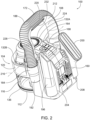
FIG. 2 is a rear perspective view of the portable vacuum cleaner ofFIG. 1 . -
FIG. 3 is a front perspective view of the portable vacuum cleaner ofFIG. 1 with the handle in a second position. -
FIG. 4 is a second perspective view of the portable vacuum cleaner ofFIG. 3 . -
FIG. 5 is a cross-sectional view of the portable vacuum cleaner, the cross-section taken through an inlet and a motor of the vacuum cleaner, as shown inFIG. 1 . -
FIG. 6 is a first side view of the portable vacuum cleaner ofFIG. 1 . -
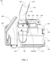
FIG. 7 is a second side view of the portable vacuum cleaner ofFIG. 1 . - Before any embodiments of the present subject matter are explained in detail, it is to be understood that the present subject matter is not limited in its application to the details of construction and the arrangement of components set forth in the following description or illustrated in the following drawings. The present subject matter is capable of other embodiments and of being practiced or of being carried out in various ways.
-
FIG. 1 illustrates a portable vacuum device 100 (e.g., vacuum cleaner) according to an embodiment of the present disclosure. Thevacuum cleaner 100 includes avacuum housing 104 that defines an interior volume therein. Thevacuum housing 104 extends vertically between atop 108 and abase 112 that is configured to rest upon a ground (or other generally horizontal surface). In the embodiment shown, theportable vacuum device 100 is movable from one location to another by carrying theportable vacuum device 100 from one location to another and therefore, omits wheels or other systems for moving thevacuum device 100 along the floor. In other embodiments, thebase 112 may be coupled to wheels. A generallycylindrical sidewall 116 extends vertically between thetop 108 and thebase 112. Thevacuum housing 104 defines amotor housing 120 and adust collection chamber 136. Themotor housing 120 is positioned vertically above thedust collection chamber 136. Written another way, themotor housing 120 is positioned nearer to thetop 108 than thedust collection chamber 136 and thedust collection chamber 136 is positioned nearer to thebase 112 than themotor housing 120. - As shown in
Fig. 5 , themotor housing 120 includes an interior volume that supports amotor 124 and animpeller 128 coupled to and driven by themotor 124. When energized, the air mover (i.e., the motor-driven impeller 128) draws air into thevacuum housing 104 through anair inlet 132A formed in themotor housing 120.Various air outlets 132B are spaced about themotor housing 120 to exhaust the air drawn in through theair inlet 132A. Thedust collection chamber 136 is a container configured to hold debris drawn in through theair inlet 132A and is separable from the remainder of thevacuum housing 104. A user input 140 (e.g., a button, a switch, slider, etc.) coupled to thehousing 104 is engaged (e.g., pressed, switched, moved) by a user to separate thedust collection chamber 136 from the remainder of thehousing 104 to permit emptying of the dust collection chamber. Anairflow passage 152 extends between theinlet 148 and thedust collection chamber 136. Theairflow passage 152 and theinlet 148 are integrally formed as a single component with the vacuum housing 104 (specifically, the upper half of thevacuum housing 104 that forms the motor housing 120). - A filter 144 (e.g., a pleated filter) extends vertically downward into the
dust collection chamber 136 to separate the air that entrains material into thedust collection chamber 136 from the material itself. Written another way, theair mover 128 draws air and entrained material (e.g., dust, debris) through theinlet 148, through theairflow passage 152, and to thedust collection chamber 136. The entrained material collects within thedust collection chamber 136 and the air passes through thefilter 144, into themotor housing 120, and through theoutlets 132B of thehousing 104. - As shown in
Fig. 2 , thehousing 104 includes abattery receptacle 160 configured to receive a removable battery 156 (Figs. 6-7 ) such that theportable vacuum device 100 is a cordless vacuum device. Theremovable battery 156 may be, for example, a rechargeable battery. In some embodiments, the battery is an 18V battery. In other embodiments, the battery is a 12V battery. In some embodiments, thebattery receptacle 156 has an identical mechanical and electrical mating interface as other dissimilar power tools (e.g., other vacuum devices, various indoor and outdoor power tools) such that theremovable battery 156 is configured to be removed from thebattery receptacle 160 and inserted into a separate power tool. Similarly, abattery 160 may be removed from a separate power tool and inserted into thebattery receptacle 160 of theportable vacuum device 100. In still other embodiments, thebattery 156 andbattery receptacle 160 may be replaced by a cord such that theportable vacuum device 100 is powered via a wall outlet. - With continued reference to
Fig. 2 , thehousing 104 further includes a plurality of user inputs (e.g., buttons, switches, sliders, etc.) that allow a user to modify the operation of thevacuum device 100. Apower button 164 is a first user input and energizes themotor 124 to generate a suction airflow when switched on. Thepower button 164 ceases to energize themotor 124 when switched off. In some embodiments, thepower button 164 is engaged by the user a first time to energize themotor 124, a second time to modify the operational mode of theportable vacuum device 100, and a third time (or for a different duration than the press used to modify the operational mode) to deenergize themotor 124. In other embodiments, a user input separate from thepower button 164 is engaged by the user to change operational modes. In still other embodiments, theportable vacuum device 100 does not include multiple operation modes and thepower button 164 only energizes and deenergizes theportable vacuum device 100. Optionally, some embodiments incorporate anindicator light 168 that includes multiple (e.g., two) LEDs (light emitting diodes) and is positioned adjacent thepower button 164 to indicate if the tool is in a first mode or a second speed mode. When thepower button 164 is engaged by a user, the operation of thevacuum device 100 is modified between the different operational modes. In one embodiment, the different operational modes may be a low suction mode and a high suction mode corresponding to different motor speeds. In another embodiment, the different operational modes may be a suction mode in which air is drawn in through theinlet 148 and a blow mode in which air is moved out of thehousing 104 through theinlet 148. In still other embodiments, the different operational modes may correspond to the use of different batteries or different attachments. In the embodiment shown, theuser inputs top 108 of thehousing 104 such that they are easily accessible from above when thevacuum device 100 is positioned on a floor surface. - A
hose 172 is coupled to theinlet 148 and defines a second airflow passage 176 (Fig. 5 ) therein, effectively extending theairflow passage 152 within thehousing 104. Thehose 172 has a length that extends between afirst end 180 and asecond end 184. Thefirst end 180 is coupled to thehousing 104 at theinlet 148. In some embodiments, thefirst end 180 is secured to thehousing 104 such that thehose 172 is not removable from thehousing 104 without tools and/or destruction. In other embodiments, thehose 172 may be secured via an attachment structure (e.g., a twist locking structure) and removable by a user. Thehose 172 is a flexible hose. In the embodiment shown, the hose has acorrugated body 188. That extends between thefirst end 180 and thesecond end 184. Thesecond end 184 includes acuff 192, forming a more rigid structure configured to receive anaccessory second end 184 is an open end, providing an inlet for thesecond airflow passage 176 to draw material from the environment into thedust collection chamber 136. With the first end coupled to theinlet 148, thesecond end 184 of theflexible hose 172 is movable relative to the housing to reach various locations within the environment around theportable vacuum device 100. -
Multiple accessories housing 104. Afirst accessory 196 is a crevice tool, attachable to thecuff 192 of thehose 172 to decrease the generally circular opening of thehose 172 to a thinner rectangular slit, configured to fit within small crevices, such as between portions of a seat in a vehicle. Asecond accessory 200 is a pet tool accessory having one or more rubber blades for removing hair, such as pet hair. Eachaccessory cuff 192 of thehose 172 to modify and/or extend the opening of thehose 172. Other accessories, such as a bristled accessory, an elongated nozzle, or an upholstery tool, may be additionally or alternatively coupled to thehousing 104 of thevacuum device 100. Each of the first andsecond accessories respective accessory holder housing 104. As shown inFig. 2 , each one of theaccessory holders respective accessory accessory holders respective accessory 196, 200 (e.g., a friction fit). In other embodiments, an attachment feature, such as a flexible detent, engages theaccessory respective accessory accessory holder - A
handle 212 is coupled to thevacuum housing 104 and provides a surface that is available to grasp by a single hand of a user to lift and move theportable vacuum device 100. Thehandle 212 is generally U-shaped (or in the shape of an inverted-U in the perspective shown), having afirst arm 224 coupled to afirst side 244 of thehousing 104 and asecond arm 228 coupled to asecond side 248 of thehousing 104. Thesecond side 248 is generally opposite thefirst side 244 such that at least a majority of thehousing 104 is located between the twoarms hand engagement portion 232 extends transverse to the twoarms arms U-shaped handle 212. - With reference to
Figs. 1-2 and5-7 , in a first position, which is a use position and an upright position, the twoarms housing 104 to thehand engagement portion 232. In the use position, thehand engagement portion 232 of thehandle 212 is presented at a height above thevacuum housing 104 to be grasped by a user. In the embodiment shown, a user is able to wrap a hand most or all of the way around thehand engagement portion 232. - With reference to
Figs. 3 and4 , thehandle 212 is rotatable about arotational axis 216 from the first position to a second position. More specifically, thefirst arm 224 is coupled to thefirst side 244 of thehousing 104 at afirst pivot point 236 and thesecond arm 228 is coupled to thesecond side 248 of thehousing 104 at asecond pivot point 240. The length of the handle extends between the first and second pivot points 236, 240 along thearms hand engagement portion 232. In one embodiment, the pivot points 236, 240 are defined by fasteners (e.g., threaded fasteners, rivets, etc.) that couple thehandle 212 to thehousing 104. Therotational axis 216 extends through the twopivot points arms housing 104. The second position is rotationally offset from the first position by approximately ninety degrees. The second position is a storage position, decreasing the overall height of thevacuum device 100. - With reference to
Figs. 6-7 , each of the first andsecond arms handle 212 include multiple detent features 252, 256 that selectively engage a recess 260 in thehousing 104 to maintain the handle in the first and second positions unless a force is applied to the handle with a magnitude sufficient to remove thedetent feature 252, 256 from the recess 260. In other embodiments, thearms housing 104. In still other embodiments, the detent features 252, 256 and recesses 260 may be switched. - The
handle 212 defines acradle 220 that receives thehose 172. Thecradle 220 has a generally U-shaped (e.g., semicircular) cross-section sized to receive the generally circular cross-section of thehose 172. In the embodiment shown, each of the first andsecond arms hand engagement portion 232 form a portion of thecradle 220. As shown inFig. 1 , a majority of the length of the hose 172 (between the first and second ends 180, 184) is positioned within thecradle 220. Nearly an entirety (e.g., at least 90%, at least 95%) of thecorrugated body 180 of thehose 172 is received within thecradle 220. Positioning thehose 172 within thecradle 220, as shown, is a storage position of thehose 172. Thehose 172 is removable (e.g., wholly removable) from thecradle 220 when in use such that thesecond end 184 of thehose 172 is movable to collect debris from different areas around thevacuum device 100. - In some embodiments, the
handle 212 and/or thehousing 104 define aretention member 264 that receives thehose 172 adjacent thesecond end 184 of thehose 172 to retain the hose within thecradle 220. As shown, theretention member 264 is a clip secured to thehousing 104 within a recess sized to receive thecuff 192. In operation, when a user repositions thehose 172 within the cradle 220 (e.g., after using the portable vacuum device 100), the user inserts a portion of thecuff 192 between theclip 264 and thehousing 104, thereby inserting a portion of theclip 264 inside the opening of thehose 172, elastically deforming theclip 264 to engage and hold thecuff 192 relative to thehousing 104. In other embodiments, theretention member 264 may be formed as a detent or recess formed within the housing that receives and engages (e.g., friction fit, detent, etc.) thecuff 192 to hold thehose 172 within thecradle 220. In other embodiments, the handle 212 (such as thesecond arm 228 of the handle 212) may include a retention member. - With the
hose 172 positioned within thecradle 220 defined by thehandle 212, rotation of the handle between the first and second positions likewise rotates thehose 172. As the hose is flexible, rotation of thehandle 212 does not dislodge thefirst end 180 of thehose 172 from theinlet 148 of thehousing 104 or dislodge thesecond end 184 from theengagement feature 264. As such, thehose 172 is configured to remain within the storage position of thehose 172 as thehandle 212 rotates between the first and second positions. The pivot points 236, 240 are positioned forward of the handle 212 (i.e., offset in the direction that thehandle 212 rotates from the first position to the second position). Therotational axis 216 defined by the pivot points 236, 240 is also therefore offset from (i.e., does not overlap) thehandle 212 and thehose 172 positioned therein. By offsetting the pivot points 236, 240 from thehose 172, thehose 172 is more easily rotated without binding, as compared to a location in which the hose overlaps the pivot points 236, 240. Written another way, if thehose 172 were aligned with the pivot points 236, 240, the hose would be significantly stretched and compressed at the pivot points 236, 240 when rotating between the first and second positions. By offsetting the pivot points 236, 240 from thehose 172, thehose 172 rotates around the pivot points 236, 240 at a distance, thereby maintaining a larger radius of thehose 172 and preventing binding or crimping of thehose 172. Further, as the use position of thehose 172 substantially separates thehose 172 from thehandle 212, thehose 172 is similarly configured to remain within the use position of thehose 172 as the handle rotates between the first and second positions. A user is able to secure or remove thehose 172 from thehandle 212 when the handle is in either of the first or second positions. - With reference to
Fig. 1 , in the first position, thevacuum device 100 has an overall height h1 measured vertically upward from a generally horizontal surface upon which the vacuum device rests. The height h1 of thevacuum device 100 in the first position extends from the base 112 in contact with the horizontal surface to thehose 172 positioned within thecradle 220 of thehandle 212. In the second position, as shown inFig. 3 , thevacuum device 100 has an overall height h2 measured vertically that is less than the height h1. The height h2 is measured from the base 112 in contact with the horizontal surface to the uppermost surface. In some embodiments, the uppermost surface is thehandle 212 in the lowered storage position. In other embodiments, rotating thehandle 212 to the storage position positions the handle entirely below the top 108 of thehousing 104 such that the uppermost surface is the top 108 of the housing. - A portable vacuum device includes a vacuum housing including a motor housing, an inlet, a dust collection chamber, and a first airflow passage extending from the inlet to the dust collection chamber, a motor positioned within the motor chamber and configured to drive an impeller to generate an airflow, a hose defining a second airflow passage between a first end of the hose and a second end of the hose, the first end coupled to the inlet of the vacuum housing, and a handle coupled to the vacuum housing and rotatable relative to the vacuum housing about a rotational axis between a first position and a second position, wherein the handle defines a cradle configured to receive the hose. The hose rotates with the handle between the first position and the second position. In some embodiments, the hose is selectively removable from the cradle of the handle with the first end of the hose coupled to the inlet of the vacuum housing. In some embodiments, the handle includes a first arm coupled to the vacuum housing and rotatable relative to the vacuum housing about the rotational axis at a first pivot point, a second arm coupled to the vacuum housing and rotatable relative to the vacuum housing about the rotational axis at a second pivot point, wherein the first pivot point is located on a first side of the vacuum housing, and wherein the second pivot point is located on a second side of the vacuum housing, opposite the first side of the vacuum housing. In some embodiments, a hand engagement portion extending transverse to the first arm and the second arm and coupling the first arm to the second arm. In some embodiments, at least a portion of the first arm, at least a portion of the second arm, and at least a portion of the hand engagement portion define the cradle configured to receive the hose. In some embodiments, the cradle of the handle has a generally U-shaped cross-section configured to receive the hose therein. In some embodiments, the vacuum housing includes a base configured to engage a ground surface during normal operation, the portable vacuum device has a first height measured vertically upward from the base when the handle is in the first position, and the portable vacuum device has a second height measured vertically upward from the base when the handle is in the second position, the second height being less than the first height. In some embodiments, the handle rotates approximately ninety degrees between the first position and the second position. In some embodiments, the hose is a flexible hose such that the first end of the hose is engaged with the inlet of the vacuum housing in the first position and the second position. In some embodiments, the hose is a corrugated hose. In some embodiments, a detent is configured to selectively retain the handle in the first position and the second position. In some embodiments, a retention member is configured to engage a portion of the hose adjacent the second end of the hose. In some embodiments, the second end of the hose includes a cuff and the vacuum housing defines one or more accessory holders configured to receive a respective accessory tool that is selectively couplable to the cuff of the hose. In some embodiments, the portable vacuum device includes a removable and rechargeable battery that is removable when the handle is in the first position and the second position. In some embodiments, the vacuum housing defines a recess configured to receive the second end of the hose when the handle is in the first position and the second position.
- A portable vacuum device includes a vacuum housing defining an inlet, a hose defining an airflow passage between a first end of the hose and a second end of the hose, the first end coupled to the inlet of the vacuum housing, and a handle coupled to the vacuum housing and rotatable relative to the vacuum housing about a rotational axis between a first position and a second position. The handle defines a cradle configured to receive the hose. The handle includes a first arm coupled to the vacuum housing and rotatable at a first pivot point, a second arm coupled to the vacuum housing and rotatable at a second pivot point, and a hand engagement portion extending transverse to the first arm and the second arm and coupling the first arm to the second arm. The hose rotates with the handle between the first position and the second position, and the first and second pivot points are offset from the hose positioned within the cradle. In some embodiments, at least a portion of the first arm, at least a portion of the second arm, and at least a portion of the hand engagement portion define the cradle configured to receive the hose.
- A portable vacuum device includes a vacuum housing defining an inlet, a handle having a length extending between a first pivot point and a second pivot point, the handle coupled to the vacuum housing and rotatable relative to the vacuum housing between a first position and a second position offset approximately 90 degrees from the first position, and a hose coupled to the inlet of the vacuum housing and configured to, in a storage position, attach to the handle such that the hose extends along a majority of the length of the handle in the first position and the second position. In some embodiments, the hose is movable from the storage position to a use position, wherein, in the use position, the hose is configured to separate from the handle. In some embodiments, the handle is generally U-shaped between the first and second pivot points, and the cross-section of the handle between the first and second pivot points is generally U-shaped to define a cradle that receives the hose in the storage position.
- Clause 1. A portable vacuum device comprising: a vacuum housing including a motor housing, an inlet, a dust collection chamber, and a first airflow passage extending from the inlet to the dust collection chamber; a motor positioned within the motor chamber and configured to drive an impeller to generate an airflow; a hose defining a second airflow passage between a first end of the hose and a second end of the hose, the first end coupled to the inlet of the vacuum housing; and a handle coupled to the vacuum housing and rotatable relative to the vacuum housing about a rotational axis between a first position and a second position, wherein the handle defines a cradle configured to receive the hose, wherein the hose rotates with the handle between the first position and the second position.
- Clause 2. The portable vacuum device of clause 1, wherein the hose is selectively removable from the cradle of the handle with the first end of the hose coupled to the inlet of the vacuum housing.
-
Clause 3. The portable vacuum device of clause 1, wherein the handle includes a first arm coupled to the vacuum housing and rotatable relative to the vacuum housing about the rotational axis at a first pivot point, a second arm coupled to the vacuum housing and rotatable relative to the vacuum housing about the rotational axis at a second pivot point, wherein the first pivot point is located on a first side of the vacuum housing, and wherein the second pivot point is located on a second side of the vacuum housing, opposite the first side of the vacuum housing. - Clause 4. The portable vacuum device of
clause 3, further comprising a hand engagement portion extending transverse to the first arm and the second arm and coupling the first arm to the second arm. -
Clause 5. The portable vacuum device of clause 4, wherein at least a portion of the first arm, at least a portion of the second arm, and at least a portion of the hand engagement portion define the cradle configured to receive the hose. - Clause 6. The portable vacuum device of clause 1, wherein the cradle of the handle has a generally U-shaped cross-section configured to receive the hose therein.
- Clause 7. The portable vacuum device of clause 1, wherein the vacuum housing includes a base configured to engage a ground surface during normal operation , wherein the portable vacuum device has a first height measured vertically upward from the base when the handle is in the first position, and wherein the portable vacuum device has a second height measured vertically upward from the base when the handle is in the second position, the second height being less than the first height.
- Clause 8. The portable vacuum device of clause 1, wherein the handle rotates approximately ninety degrees between the first position and the second position.
- Clause 9. The portable vacuum device of clause 1, wherein the hose is a flexible hose such that the first end of the hose is engaged with the inlet of the vacuum housing in the first position and the second position.
- Clause 10. The portable vacuum device of clause 9, wherein the hose is a corrugated hose.
- Clause 11. The portable vacuum device of clause 1, further comprising a detent configured to selectively retain the handle in the first position and the second position.
- Clause 12. The portable vacuum device of clause 1, further comprising a retention member configured to engage a portion of the hose adjacent the second end of the hose.
- Clause 13. The portable vacuum device of clause 1, wherein the second end of the hose includes a cuff, wherein the vacuum housing defines one or more accessory holders configured to receive a respective accessory tool that is selectively couplable to the cuff of the hose.
- Clause 14. The portable vacuum device of clause 1, further comprising a removable and rechargeable battery, wherein the removable and rechargeable battery is removable when the handle is in the first position and the second position.
- Clause 15. The portable vacuum device of clause 1, wherein the vacuum housing defines a recess configured to receive the second end of the hose when the handle is in the first position and the second position.
- Clause 16. A portable vacuum device comprising: a vacuum housing defining an inlet; a hose defining an airflow passage between a first end of the hose and a second end of the hose, the first end coupled to the inlet of the vacuum housing, and a handle coupled to the vacuum housing and rotatable relative to the vacuum housing about a rotational axis between a first position and a second position, wherein the handle defines a cradle configured to receive the hose, wherein the handle includes a first arm coupled to the vacuum housing and rotatable at a first pivot point, a second arm coupled to the vacuum housing and rotatable at a second pivot point, and a hand engagement portion extending transverse to the first arm and the second arm and coupling the first arm to the second arm, wherein the hose rotates with the handle between the first position and the second position, and wherein the first and second pivot points are offset from the hose positioned within the cradle.
- Clause 17. The portable vacuum device of clause 16, wherein at least a portion of the first arm, at least a portion of the second arm, and at least a portion of the hand engagement portion define the cradle configured to receive the hose.
- Clause 18. A portable vacuum device comprising: a vacuum housing defining an inlet; a handle having a length extending between a first pivot point and a second pivot point, the handle coupled to the vacuum housing and rotatable relative to the vacuum housing between a first position and a second position offset approximately 90 degrees from the first position; and a hose coupled to the inlet of the vacuum housing and configured to, in a storage position, attach to the handle such that the hose extends along a majority of the length of the handle in the first position and the second position.
- Clause 19. The portable vacuum device of clause 18, wherein the hose is movable from the storage position to a use position, wherein, in the use position, the hose is configured to separate from the handle.
- Clause 20. The portable vacuum device of clause 18, wherein the handle is generally U-shaped between the first and second pivot points, and wherein the cross-section of the handle between the first and second pivot points is generally U-shaped to define a cradle that receives the hose in the storage position.
- Although the present subject matter has been described in detail with reference to certain preferred embodiments, variations and modifications exist within the scope of one or more independent aspects of the subject matter as described.
Claims (15)
- A portable vacuum device comprising:a vacuum housing including a motor housing, an inlet, a dust collection chamber, and a first airflow passage extending from the inlet to the dust collection chamber;a motor positioned within the motor chamber and configured to drive an impeller to generate an airflow;a hose defining a second airflow passage between a first end of the hose and a second end of the hose, the first end coupled to the inlet of the vacuum housing; anda handle coupled to the vacuum housing and rotatable relative to the vacuum housing about a rotational axis between a first position and a second position, wherein the handle defines a cradle configured to receive the hose,wherein the hose rotates with the handle between the first position and the second position.
- The portable vacuum device of claim 1, wherein the hose is selectively removable from the cradle of the handle with the first end of the hose coupled to the inlet of the vacuum housing.
- The portable vacuum device of claim 1, wherein the handle includes a first arm coupled to the vacuum housing and rotatable relative to the vacuum housing about the rotational axis at a first pivot point, a second arm coupled to the vacuum housing and rotatable relative to the vacuum housing about the rotational axis at a second pivot point, wherein the first pivot point is located on a first side of the vacuum housing, and wherein the second pivot point is located on a second side of the vacuum housing, opposite the first side of the vacuum housing.
- The portable vacuum device of claim 3, further comprising a hand engagement portion extending transverse to the first arm and the second arm and coupling the first arm to the second arm.
- The portable vacuum device of claim 4, wherein at least a portion of the first arm, at least a portion of the second arm, and at least a portion of the hand engagement portion define the cradle configured to receive the hose.
- The portable vacuum device of claim 1, wherein the cradle of the handle has a generally U-shaped cross-section configured to receive the hose therein.
- The portable vacuum device of claim 1, wherein the vacuum housing includes a base configured to engage a ground surface during normal operation , wherein the portable vacuum device has a first height measured vertically upward from the base when the handle is in the first position, and wherein the portable vacuum device has a second height measured vertically upward from the base when the handle is in the second position, the second height being less than the first height.
- The portable vacuum device of claim 1, wherein the handle rotates approximately ninety degrees between the first position and the second position.
- The portable vacuum device of claim 1, wherein the hose is a flexible hose such that the first end of the hose is engaged with the inlet of the vacuum housing in the first position and the second position.
- The portable vacuum device of claim 9, wherein the hose is a corrugated hose.
- The portable vacuum device of claim 1, further comprising a detent configured to selectively retain the handle in the first position and the second position.
- The portable vacuum device of claim 1, further comprising a retention member configured to engage a portion of the hose adjacent the second end of the hose.
- The portable vacuum device of claim 1, wherein the second end of the hose includes a cuff, wherein the vacuum housing defines one or more accessory holders configured to receive a respective accessory tool that is selectively couplable to the cuff of the hose.
- A portable vacuum device comprising:a vacuum housing defining an inlet;a hose defining an airflow passage between a first end of the hose and a second end of the hose, the first end coupled to the inlet of the vacuum housing, anda handle coupled to the vacuum housing and rotatable relative to the vacuum housing about a rotational axis between a first position and a second position,wherein the handle defines a cradle configured to receive the hose,wherein the handle includes a first arm coupled to the vacuum housing and rotatable at a first pivot point, a second arm coupled to the vacuum housing and rotatable at a second pivot point, and a hand engagement portion extending transverse to the first arm and the second arm and coupling the first arm to the second arm,wherein the hose rotates with the handle between the first position and the second position, andwherein the first and second pivot points are offset from the hose positioned within the cradle.
- A portable vacuum device comprising:a vacuum housing defining an inlet;a handle having a length extending between a first pivot point and a second pivot point, the handle coupled to the vacuum housing and rotatable relative to the vacuum housing between a first position and a second position offset approximately 90 degrees from the first position; anda hose coupled to the inlet of the vacuum housing and configured to, in a storage position, attach to the handle such that the hose extends along a majority of the length of the handle in the first position and the second position.
Applications Claiming Priority (1)
| Application Number | Priority Date | Filing Date | Title |
|---|---|---|---|
| US18/489,526 US20250127352A1 (en) | 2023-10-18 | 2023-10-18 | Portable vacuum cleaner |
Publications (1)
| Publication Number | Publication Date |
|---|---|
| EP4541244A1 true EP4541244A1 (en) | 2025-04-23 |
Family
ID=92899938
Family Applications (1)
| Application Number | Title | Priority Date | Filing Date |
|---|---|---|---|
| EP24202245.7A Pending EP4541244A1 (en) | 2023-10-18 | 2024-09-24 | Portable vacuum cleaner |
Country Status (4)
| Country | Link |
|---|---|
| US (1) | US20250127352A1 (en) |
| EP (1) | EP4541244A1 (en) |
| CN (1) | CN119837436A (en) |
| AU (1) | AU2024220055A1 (en) |
Citations (3)
| Publication number | Priority date | Publication date | Assignee | Title |
|---|---|---|---|---|
| US20180132683A1 (en) * | 2016-11-15 | 2018-05-17 | Black & Decker Inc. | Cleaning device |
| US10548267B2 (en) * | 2016-08-08 | 2020-02-04 | Randy Streetman | Vacuum debris collection apparatus |
| US20220117451A1 (en) * | 2019-07-04 | 2022-04-21 | Positec Power Tools (Suzhou) Co., Ltd. | Vacuum cleaner |
Family Cites Families (1)
| Publication number | Priority date | Publication date | Assignee | Title |
|---|---|---|---|---|
| CN111281260A (en) * | 2018-12-07 | 2020-06-16 | 苏州宝时得电动工具有限公司 | Vehicle-mounted dust collector |
-
2023
- 2023-10-18 US US18/489,526 patent/US20250127352A1/en active Pending
-
2024
- 2024-09-24 EP EP24202245.7A patent/EP4541244A1/en active Pending
- 2024-09-25 AU AU2024220055A patent/AU2024220055A1/en active Pending
- 2024-09-26 CN CN202411353464.0A patent/CN119837436A/en active Pending
Patent Citations (3)
| Publication number | Priority date | Publication date | Assignee | Title |
|---|---|---|---|---|
| US10548267B2 (en) * | 2016-08-08 | 2020-02-04 | Randy Streetman | Vacuum debris collection apparatus |
| US20180132683A1 (en) * | 2016-11-15 | 2018-05-17 | Black & Decker Inc. | Cleaning device |
| US20220117451A1 (en) * | 2019-07-04 | 2022-04-21 | Positec Power Tools (Suzhou) Co., Ltd. | Vacuum cleaner |
Also Published As
| Publication number | Publication date |
|---|---|
| CN119837436A (en) | 2025-04-18 |
| AU2024220055A1 (en) | 2025-05-08 |
| US20250127352A1 (en) | 2025-04-24 |
Similar Documents
| Publication | Publication Date | Title |
|---|---|---|
| US12543905B2 (en) | Surface cleaning apparatus | |
| US9775484B2 (en) | Surface cleaning apparatus | |
| EP3641609B1 (en) | Surface cleaning apparatus | |
| CN110996739B (en) | Surface Cleaning Equipment | |
| EP3576588B1 (en) | A tool for a surface cleaning apparatus | |
| GB2268875A (en) | Vacuum cleaner | |
| US20190261824A1 (en) | All in the head surface cleaning apparatus | |
| EP3833233B1 (en) | Handheld vacuum cleaner | |
| CN112543609A (en) | Vacuum cleaning device | |
| JP6267896B2 (en) | Dual-use dust collector | |
| JP2018015323A (en) | Electric cleaning device | |
| GB2307849A (en) | A suction cleaner | |
| US20250127352A1 (en) | Portable vacuum cleaner | |
| KR101512232B1 (en) | Dust collecting device and electric cleaner with the same | |
| JP5382620B2 (en) | Portable vacuum cleaner | |
| CN216167166U (en) | Electric Floor Sweeper | |
| US20240108187A1 (en) | Vacuum Device | |
| JP7482288B1 (en) | Electric Vacuum Equipment | |
| JP2018015325A (en) | Electric cleaning device | |
| JP7013038B2 (en) | Vacuum cleaner with bag | |
| JP2006198152A (en) | Electric vacuum cleaner | |
| CN112566534A (en) | Battery powered vacuum cleaner | |
| EP4049572A2 (en) | Dustpan accessory tool for vacuum cleaner | |
| CN109008788A (en) | Handheld Cleaning Equipment | |
| JP4519662B2 (en) | Vacuum cleaner |
Legal Events
| Date | Code | Title | Description |
|---|---|---|---|
| PUAI | Public reference made under article 153(3) epc to a published international application that has entered the european phase |
Free format text: ORIGINAL CODE: 0009012 |
|
| STAA | Information on the status of an ep patent application or granted ep patent |
Free format text: STATUS: THE APPLICATION HAS BEEN PUBLISHED |
|
| AK | Designated contracting states |
Kind code of ref document: A1 Designated state(s): AL AT BE BG CH CY CZ DE DK EE ES FI FR GB GR HR HU IE IS IT LI LT LU LV MC ME MK MT NL NO PL PT RO RS SE SI SK SM TR |
|
| STAA | Information on the status of an ep patent application or granted ep patent |
Free format text: STATUS: REQUEST FOR EXAMINATION WAS MADE |
|
| GRAP | Despatch of communication of intention to grant a patent |
Free format text: ORIGINAL CODE: EPIDOSNIGR1 |
|
| STAA | Information on the status of an ep patent application or granted ep patent |
Free format text: STATUS: GRANT OF PATENT IS INTENDED |
|
| 17P | Request for examination filed |
Effective date: 20251021 |
|
| INTG | Intention to grant announced |
Effective date: 20251110 |
|
| RIC1 | Information provided on ipc code assigned before grant |
Ipc: A47L 9/24 20060101AFI20251031BHEP Ipc: A47L 9/32 20060101ALI20251031BHEP |
|
| GRAJ | Information related to disapproval of communication of intention to grant by the applicant or resumption of examination proceedings by the epo deleted |
Free format text: ORIGINAL CODE: EPIDOSDIGR1 |
|
| STAA | Information on the status of an ep patent application or granted ep patent |
Free format text: STATUS: REQUEST FOR EXAMINATION WAS MADE |
|
| INTC | Intention to grant announced (deleted) | ||
| GRAP | Despatch of communication of intention to grant a patent |
Free format text: ORIGINAL CODE: EPIDOSNIGR1 |
|
| STAA | Information on the status of an ep patent application or granted ep patent |
Free format text: STATUS: GRANT OF PATENT IS INTENDED |
|
| INTG | Intention to grant announced |
Effective date: 20260430 |