EP4541223A1 - Drying device - Google Patents
Drying device Download PDFInfo
- Publication number
- EP4541223A1 EP4541223A1 EP23204031.1A EP23204031A EP4541223A1 EP 4541223 A1 EP4541223 A1 EP 4541223A1 EP 23204031 A EP23204031 A EP 23204031A EP 4541223 A1 EP4541223 A1 EP 4541223A1
- Authority
- EP
- European Patent Office
- Prior art keywords
- drying device
- fan
- hub portion
- air
- heat source
- Prior art date
- Legal status (The legal status is an assumption and is not a legal conclusion. Google has not performed a legal analysis and makes no representation as to the accuracy of the status listed.)
- Withdrawn
Links
Images


Classifications
-
- A—HUMAN NECESSITIES
- A45—HAND OR TRAVELLING ARTICLES
- A45D—HAIRDRESSING OR SHAVING EQUIPMENT; EQUIPMENT FOR COSMETICS OR COSMETIC TREATMENTS, e.g. FOR MANICURING OR PEDICURING
- A45D20/00—Hair drying devices; Accessories therefor
- A45D20/04—Hot-air producers
- A45D20/08—Hot-air producers heated electrically
-
- A—HUMAN NECESSITIES
- A45—HAND OR TRAVELLING ARTICLES
- A45D—HAIRDRESSING OR SHAVING EQUIPMENT; EQUIPMENT FOR COSMETICS OR COSMETIC TREATMENTS, e.g. FOR MANICURING OR PEDICURING
- A45D20/00—Hair drying devices; Accessories therefor
- A45D20/04—Hot-air producers
- A45D20/08—Hot-air producers heated electrically
- A45D20/10—Hand-held drying devices, e.g. air douches
-
- A—HUMAN NECESSITIES
- A47—FURNITURE; DOMESTIC ARTICLES OR APPLIANCES; COFFEE MILLS; SPICE MILLS; SUCTION CLEANERS IN GENERAL
- A47K—SANITARY EQUIPMENT; ACCESSORIES THEREFOR, e.g. TOILET ACCESSORIES
- A47K10/00—Body-drying implements; Toilet paper; Holders therefor
- A47K10/48—Drying by means of hot air
-
- F—MECHANICAL ENGINEERING; LIGHTING; HEATING; WEAPONS; BLASTING
- F04—POSITIVE - DISPLACEMENT MACHINES FOR LIQUIDS; PUMPS FOR LIQUIDS OR ELASTIC FLUIDS
- F04D—NON-POSITIVE-DISPLACEMENT PUMPS
- F04D25/00—Pumping installations or systems
- F04D25/02—Units comprising pumps and their driving means
- F04D25/08—Units comprising pumps and their driving means the working fluid being air, e.g. for ventilation
- F04D25/084—Units comprising pumps and their driving means the working fluid being air, e.g. for ventilation hand fans
-
- F—MECHANICAL ENGINEERING; LIGHTING; HEATING; WEAPONS; BLASTING
- F04—POSITIVE - DISPLACEMENT MACHINES FOR LIQUIDS; PUMPS FOR LIQUIDS OR ELASTIC FLUIDS
- F04D—NON-POSITIVE-DISPLACEMENT PUMPS
- F04D29/00—Details, component parts, or accessories
- F04D29/26—Rotors specially for elastic fluids
- F04D29/32—Rotors specially for elastic fluids for axial flow pumps
- F04D29/38—Blades
- F04D29/384—Blades characterised by form
Definitions
- the invention relates to a drying device, such as a hair dryer or a hand dryer.
- Drying devices such as hairdryers and hand dryers typically include a heating element and a fan for air propulsion, to blow warm air towards an object to be dried (e.g., hair or a hand).
- Fans used in devices such as hairdryers are typically driven by a motor and, in some cases, significant amounts of energy can be required to drive the motor which in turn drives the fan. A stronger flow of air from the drying device can be achieved by using a larger fan.
- larger amounts of energy are required for larger fans, meaning a larger motor may be required, and larger amounts of energy may need to be provided to power the motor.
- a drying device such as a hair dryer or a hand dryer, which is capable of providing at least the same drying effect as existing drying devices, but which uses less power, or is more efficient. It would also be desirable to have a drying device that generates less noise during use, compared to existing drying devices that include a fan. The inventor of the present disclosure has recognised that one or both of these improvements may be realised by using a different type of fan in a drying device.
- a drying device includes, among other features, a toroidal fan for generating a flow of air.
- a toroidal fan which may have the same size (e.g., diameter) as a traditional axial flow fan, is capable of generating greater air flow than an equivalent (e.g., similar sized) axial flow fan.
- toroidal fans are typically quieter than fans traditionally used in drying devices, meaning that devices in which toroidal fans are used can be quieter than devices using traditional fans, providing a better user experience.
- the toroidal fan may include a hub portion; and at least one blade, each of the at least one blade connected to the hub portion at a first connection position and at a second connection position, such that a space is formed between the at least one blade and the hub portion.
- the first connection position and the second connection position may be at different distances along the length of the hub portion.
- the drying device may further comprise at least one heat source disposed at least partially within the housing, the at least one heat source configured such that heat generated by the at least one heat source is transferred to the flow of air generated by the toroidal fan.
- the at least one heat source may be located concentrically around the hub portion.
- the at least one heat source may be located at least partially within the space formed between the at least one blade and the hub portion.
- the at least one heat source is located in at least one of the following positions: i) between the toroidal fan and the air inlet; and ii) between the toroidal fan and the air outlet.
- the at least one heat source may be located at least partially within the hub portion.
- the housing may comprise a wall.
- the wall may comprise a recessed channel configured to receive part of the at least one blade of the toroidal fan.
- the recessed channel may be positioned concentrically around the hub portion.
- the drying device may further comprise a motor configured to drive the toroidal fan.
- the motor may, for example, be located at least partially within the hub portion.
- the drying device may be configured to at least partially dry a body part of a user.
- the drying device may comprise a hairdryer or a hand dryer.
- the drying device may comprise a hairdryer and may further comprise a handle to be held by a user during use.
- drying devices such as hand dryers and hair dryers.
- the drying devices disclosed herein include features intended to improve the efficiency of such devices when compared to existing drying devices, and to improve the experience of a user of such devices, by generating less noise than existing drying devices.
- a different type of fan than is traditionally used in such drying devices, namely a toroidal fan.
- each blade extends from a central hub/axis to a blade tip. It is the tips of the blades that create drag and energy losses, and also generate noise as the fan rotates.
- Each blade of a toroidal fan does not have a blade tip.
- each blade of the toroidal fan may be toroidal (e.g., curved or having a curved shape) with both of the two ends of the blade connected to a hub portion.
- the two ends of the blade may be connected at a same position of the hub portion or at two different positions.
- Each blade of a toroidal fan may be substantially circular, teardrop-shaped, arch-shaped or n-shaped.
- Existing drying devices include fans having a plurality of blades (e.g., twisted blades) attached to or extending from a central core or hub.
- a motor is used to drive the fan, which causes the hub and the blades to rotate about a central axis.
- a flow of air is generated, which helps to dry objects.
- propellers such as propellers installed on boats and aeroplanes. As a propeller rotates, air is forced in one direction, causing movement of the propeller (and any object attached to the propeller) in the opposite direction.
- a drying device includes a toroidal fan rather than a traditional fan.
- Fig. 1 is a schematic illustration of an example of a drying device 100 according to various embodiments.
- the drying device 100 comprises a housing 102 having an air inlet 104 via which air is received into the drying device and an air outlet 106 via which air is propelled from the drying device.
- the drying device 100 further comprises a toroidal fan 108 disposed at least partially within the housing 102, the toroidal fan being configured to generate a flow of air along an airflow path towards the air outlet 106 of the housing.
- the drying device 100 described herein with reference to the figures may include features other than those shown.
- the drying device may include one or more components for supporting the toroidal fan 108 or other components relative to the housing 102 or relative to one another, an axis on which the toroidal fan can rotate, a mechanism for driving the toroidal fan, a power source or a mechanism for providing power to the toroidal fan, and so on.
- the drying device 100 may further comprise a motor (not shown) configured to drive the toroidal fan 108.
- the motor may be located next to (e.g., along the axis of) the toroidal fan 108, for example between the toroidal fan and the air inlet 104 or between the toroidal fan and the air outlet 106. In other embodiments, however, the motor may be located at least partially within the hub portion 110 of the toroidal fan 108. By locating the motor within the hub portion 110 of the toroidal fan 108, savings may be made in terms of space and volume occupied by components within the drying device 100, meaning the drying device can be smaller than if the motor is positioned next to the toroidal fan.
- An advantage of using the toroidal fan 108 is that it is capable of generating an improved flow of air (e.g., more powerful) than a traditional fan, and may generate less noise.
- the toroidal fan 108 can be driven at a slower rotational speed (e.g., a lower number of rotations per minute, RPM) while still achieving the same drying effect as a traditional fan used in existing drying devices.
- RPM rotational speed
- the toroidal fan 108 can be even quieter, and can be driven with less power (if driven at a lower RPM), potentially reducing running costs and energy usage, and providing a better user experience.
- the toroidal fan 108 is disposed fully within the housing 102. However, in other examples, part of the toroidal fan 108 may extend partially outside of the housing 102.
- One or both of the air inlet 104 and the air outlet 106 may include a grill or grating (not shown) configured to at least partially cover the air inlet and/or air outlet, to prevent objects (e.g., fingers) from being inserted into the housing 102 via the air inlet and/or air outlet.
- a grill or grating may serve as a safety mechanism, reducing the likelihood that a person may be injured by placing their finger inside the drying device 100, and reducing the likelihood that other objects may be damaged by being inserted or falling into the drying device, where such fingers or objects could be struck by the toroidal fan 108 as it rotates.
- the air inlet 104 may, for example, be configured to receive ambient air from outside the housing 102.
- the air may, for example, be drawn into the air inlet 104 by the rotation of the toroidal fan 108.
- the air may then be propelled along an airflow path indicated by the arrows A towards the air outlet 106.
- Air propelled out of the air outlet 106 of the drying device 100 may be directed towards an object that is to be dried, such as air or hands of a user.
- the toroidal fan 108 may take many different forms, but in general may include a hub portion 110 and at least one blade 112. In the example shown in Fig. 1 , the toroidal fan 108 includes a first blade 112a, a second blade 112b, a third blade 112c and a fourth blade 112d. In other examples, however, the toroidal fan 108 may include more or fewer blades.
- the hub portion 110 serves as a core, to which the at least one blade 112 is connected or from which the at least one blade extends.
- Fig. 2 is an illustration of an example of a toroidal fan 108'.
- the toroidal fan 108' is a variation of the toroidal fan 108 shown in Fig. 1 . While generally the toroidal fan 108, 108' may include at least one blade 112, the toroidal fan 108' shown in Fig. 2 includes a hub portion 110 and a single blade 112' (e.g., the first blade). Each blade of the at least one blade (e.g., the first blade 112') is connected to the hub portion 110 in at least one position. In some examples, two ends of each blade may be connected to the same position of the hub portion 110, such that each blade forms a substantially round (e.g., 'O') or teardrop shape.
- a substantially round e.g., 'O'
- each blade may be connected to the hub portion 110 at a first connection position (e.g., a first end of the blade may be connected at the first connection position) and at a second connection position (e.g., a second end of the blade may be connected at the second connection position), such that a space is formed between the at least one blade (e.g., the first blade in this example) and the hub portion.
- the first connection position and the second connection position may be spaced apart from one another along a length of the hub portion and/or along (e.g., about) a circumference of the hub portion.
- the first blade 112' of the toroidal fan 108' may have a curved formation or may be arch-shaped or n-shaped, such that a space is formed between the hub portion 110 and the part of the first blade between the first connection position and the second connection position.
- the at least one blade may comprise a first blade 112a and a second blade 112b.
- the first connection position is at a first distance along a length of the hub portion
- the second connection position is at a second distance along the length of the hub portion.
- the first connection position and the second connection position are at different distances along the length of the hub portion.
- the two ends of a blade 112 are connected at different distances along the length of the hub portion 110.
- One or more of the blades 112 may be arch-shaped, such that the two ends of the blade are connected to (e.g., formed integrally with or attached to) the hub portion 110, and the part of the blade between the ends is spaced apart from the hub portion.
- the drying device 100 may, in some embodiments, further comprise at least one heat source 302 disposed at least partially within the housing 102, the at least one heat source configured such that heat generated by the at least one heat source is transferred to the flow of air generated by the toroidal fan 108.
- the heat source 302 may be positioned at various locations within the housing 102, depending on the size and shape of the drying device 100 and on the amount of space available within the housing 102.
- Fig. 3 is a schematic illustration of an example of the drying device 100 having a heat source 302 at a first position.
- the at least one heat source 302 may be located concentrically around the hub portion 110.
- the at least one heat source 302 may be substantially ring-shaped or annular, having a centre point that lies on a central axis of the hub portion 110.
- the at least one heat source 302 may be located at least partially within the space formed between the at least one blade 112 and the hub portion 110.
- a ring-shaped heat source 302 e.g., a coil annulus
- Such a heat source may be attached to the hub portion 110 at a region that does not rotate during use.
- the at least one heat source 302 may, in some embodiments, be positioned within the space or volume formed between a blade 112 and the hub portion 110. In this way, as the toroidal fan 108 rotates, the blades 112 of the toroidal fan propel warm air (i.e., air that has been heated by the at least one heat source 302) towards the air outlet 106.
- the at least one heat source 302 may have a size and/or shape based on the clearance between the blades 112 and the hub portion 110, such that, as the toroidal fan 108 rotates, the blades are not obstructed by the at least one heat source.
- an annular or ring-shaped heat source 302 may be provided adjacent to the at least one blade 112, along a length (e.g., axis of) the hub portion 110.
- multiple heat sources may be provided within the space formed between the blades 112 and the hub portion 110.
- multiple heat sources 302 may be connected to spokes extending from part of the hub portion 110 that does not rotate during use.
- alternative arrangements may be used to provide one or more heat sources 302 within the space formed between the blades 112 of the toroidal fan 108 and the hub portion 110 of the toroidal fan.
- the heat source(s) may be stationary relative to the toroidal fab 108 as it rotates.
- the heat source 302 may be connected to a static or stationary part of the hub portion 110.
- an internal part of the hub portion 110 may remain static (e.g., not rotating with the blades of the toroidal fan 108), and this may support the heat source 302 or provide a connection to the heat source.
- the hub portion 110 may include a split or gap between the positions where the blades 112 are connected to the hub portion, and the heat source 302 may be connected to a connector within the split or gap.
- Positioning the at least one heat source 302 within the footprint or volume of the toroidal fan 108 can help to reduce the overall size the drying device 100, since the at least one the source does not need to be placed next to the toroidal fan in this embodiment.
- arranging the at least one heat source 302 in this way may lead to improvements in efficiency of the drying device 100 since, as the air is heated by the at least one heat source, the air expands and may therefore be propelled at a greater speed through the air outlet 106.
- Positioning the at least one heat source 302 as shown in the embodiment of Fig. 3 also reduces disruption of airflow generated by the toroidal fan 108, while still providing effective heating of the air to be propelled by the fan.
- the at least one heat source 302 may take any suitable form for providing heat to the surrounding air.
- the at least one heat source 302 may comprise a coil heater, a "zigzag" heater, a ceramic heater, a ceramic ring, or the like.
- the at least one heat source 302 may be located between the toroidal fan 108 and the air inlet 104 or between the toroidal fan and the air outlet 106. In some embodiments, a first heat source 302 may be located between the toroidal fan 108 and the air inlet 104 and a second heat source may be located between the toroidal fan and the air outlet 106.
- Fig. 4 is a schematic illustration of an example of the drying device 100 in which the heat source 302 is located between the toroidal fan 108 and the air outlet 106.
- the toroidal fan 108 may propel air towards and through or past the heat source 302 such that the temperature of the propelled air increases as it passes the heat source.
- the heat source 302 may be configured such that air is able to pass through it or past it without significantly being impeded.
- the heat source 302 may be located next to or outside the air pathway along which areas propelled by the toroidal fan 108, so that the air is heated as the propelled air passes the heat source. In this way, a fast and/or powerful flow of air may be propelled from the drying device 100.
- Fig. 5 is a schematic illustration of an example of the drying device 100 in which the heat source 302 is located between the air inlet 104 and the toroidal fan 108.
- the heat source 302 may heat air drawn into the drying device via the air inlet 104, such that the temperature of the air is increased before it is propelled towards the air outlet 106 by the toroidal fan 108.
- multiple heat sources 302 may be provided within a drying device 100.
- a first heat source 302 may be provided in the location shown in Fig. 4 and a second heat source may be provided in the location shown in Fig. 5 .
- the at least one heat source 302 may be located at least partially within the hub portion 110 of the toroidal fan 108.
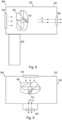
- Fig. 6 is a schematic illustration of an example of the drying device 100 in which the heat source 302 is located within the hub portion 110.
- the heat source 302 may be configured to heat the hub portion 100 and therefore the toroidal fan 108 and/or air surrounding the hub portion.
- a toroidal fan 108 helps to reduce the noise generated compared to a traditional fan.
- the noise generated may be reduced further by configuring the drying device 100 such that the toroidal fan rotates at least partially within a channel.
- Fig. 7 is a schematic illustration of a further example of the drying device 100 in which a channel is formed to aid with the reduction of noise generated by the toroidal fan 108.
- the housing 102 of the drying device 100 may comprise a wall, and the wall may comprise a recessed channel 702 configured to receive part of the at least one blade of the toroidal fan 108.
- a recessed channel 702 configured to receive part of the at least one blade of the toroidal fan 108.
- the recessed channel 702 may be ring-shaped.
- the recessed channel 702 may be positioned concentrically around the hub portion 110.
- the toroidal fan 108 may be positioned such that an end or tip of each blade 112 is within the recessed channel 702. In this way, amount of noise that is generated at the end or tip of each blade 112 of the toroidal fan 108 is reduced, due to the interaction of soundwaves with walls of the recessed channel.
- the toroidal fan 108 is shown to be narrower than (e.g., not as wide as) the toroidal fan shown in the other figures.
- a narrower fan may be used when it is intended to keep the size of the drying device 100 small.
- the drying device 100 disclosed herein may be suitable for drying any object, but may be configured to at least partially dry a body part of a user.
- the drying device 100 may comprise a hair dryer or a hand dryer.
- Fig. 8 is a schematic illustration of an example of a hair dryer 800
- Fig. 9 is a schematic illustration of an example of a hand dryer 900.
- the hair dryer 800 may comprise the drying device 100 and further comprises a handle 802 to be held by a user during use.
- the handle 802 may include one or more controls, such as buttons or switches that the user may use to operate the hair dryer 800, for example to switch the hairdryer on and off, to adjust the speed of rotation of the toroidal fan 108 and/or to adjust the temperature to which air is to be heated by the heat source 302.
- the hand dryer 900 may comprise the drying device 100, and may be configured such that a user positions their hands beneath the air outlet 106 to be dried.
- Other configurations of the drying device 100 may be implemented into devices used to dry other items.
- a drying device that can provide an improved user experience due to reduced noise generation (e.g., as a result of using a toroidal fan instead of a traditional noisier fan) and that is capable of effectively and efficiently drying an object.
- a computer program may be stored or distributed on a suitable medium, such as an optical storage medium or a solid-state medium supplied together with or as part of other hardware, but may also be distributed in other forms, such as via the Internet or other wired or wireless telecommunication systems. Any reference signs in the claims should not be construed as limiting the scope.
Landscapes
- Engineering & Computer Science (AREA)
- Mechanical Engineering (AREA)
- General Engineering & Computer Science (AREA)
- Health & Medical Sciences (AREA)
- Public Health (AREA)
- Structures Of Non-Positive Displacement Pumps (AREA)
Abstract
According to an aspect, there is provided a drying device (100) comprising a housing (102) having an air inlet (104) via which air is received into the drying device and an air outlet (106) via which air is propelled from the drying device; and a toroidal fan (108) disposed at least partially within the housing, the toroidal fan configured to generate a flow of air along an airflow path towards the air outlet of the housing.
Description
- The invention relates to a drying device, such as a hair dryer or a hand dryer.
- Drying devices, such as hairdryers and hand dryers typically include a heating element and a fan for air propulsion, to blow warm air towards an object to be dried (e.g., hair or a hand). Fans used in devices such as hairdryers are typically driven by a motor and, in some cases, significant amounts of energy can be required to drive the motor which in turn drives the fan. A stronger flow of air from the drying device can be achieved by using a larger fan. However, larger amounts of energy are required for larger fans, meaning a larger motor may be required, and larger amounts of energy may need to be provided to power the motor.
- Another downside of existing drying devices is that, in use, fans can generate large amounts of noise as they rotate, which can cause a negative experience for a user of a drying device that includes such a fan.
- There is, therefore, a desire for a drying device having a fan that addresses at least some of these issues.
- It would be desirable to have a drying device, such as a hair dryer or a hand dryer, which is capable of providing at least the same drying effect as existing drying devices, but which uses less power, or is more efficient. It would also be desirable to have a drying device that generates less noise during use, compared to existing drying devices that include a fan. The inventor of the present disclosure has recognised that one or both of these improvements may be realised by using a different type of fan in a drying device. Specifically, according to embodiments disclosed herein, a drying device includes, among other features, a toroidal fan for generating a flow of air. A toroidal fan, which may have the same size (e.g., diameter) as a traditional axial flow fan, is capable of generating greater air flow than an equivalent (e.g., similar sized) axial flow fan. Moreover, toroidal fans are typically quieter than fans traditionally used in drying devices, meaning that devices in which toroidal fans are used can be quieter than devices using traditional fans, providing a better user experience.
- According to a first specific aspect, there is provided a drying device comprising a housing having an air inlet via which air is received into the drying device and an air outlet via which air is propelled from the drying device; and a toroidal fan disposed at least partially within the housing, the toroidal fan configured to generate a flow of air along an airflow path towards the air outlet of the housing.
- The toroidal fan may include a hub portion; and at least one blade, each of the at least one blade connected to the hub portion at a first connection position and at a second connection position, such that a space is formed between the at least one blade and the hub portion.
- In some embodiments, the first connection position and the second connection position may be at different distances along the length of the hub portion.
- In some embodiments, the drying device may further comprise at least one heat source disposed at least partially within the housing, the at least one heat source configured such that heat generated by the at least one heat source is transferred to the flow of air generated by the toroidal fan.
- The at least one heat source may be located concentrically around the hub portion.
- In some embodiments, the at least one heat source may be located at least partially within the space formed between the at least one blade and the hub portion.
- In other embodiments, the at least one heat source is located in at least one of the following positions: i) between the toroidal fan and the air inlet; and ii) between the toroidal fan and the air outlet.
- The at least one heat source may be located at least partially within the hub portion.
- In some embodiments, the housing may comprise a wall. The wall may comprise a recessed channel configured to receive part of the at least one blade of the toroidal fan.
- The recessed channel may be positioned concentrically around the hub portion.
- In some embodiments, the drying device may further comprise a motor configured to drive the toroidal fan.
- The motor may, for example, be located at least partially within the hub portion.
- The drying device may be configured to at least partially dry a body part of a user.
- In some embodiments, the drying device may comprise a hairdryer or a hand dryer.
- In some embodiments, the drying device may comprise a hairdryer and may further comprise a handle to be held by a user during use.
- These and other aspects will be apparent from and elucidated with reference to the embodiment(s) described hereinafter.
- Exemplary embodiments will now be described, by way of example only, with reference to the following drawings, in which:
-
Fig. 1 is a schematic illustration of an example of a drying device according various embodiments; -
Fig. 2 is an illustration of an example of part of a toroidal fan; -
Fig. 3 is a schematic illustration of an example of a drying device according various embodiments; -
Fig. 4 is a schematic illustration of an example of a drying device according various embodiments; -
Fig. 5 is a schematic illustration of an example of a drying device according various embodiments; -
Fig. 6 is a schematic illustration of an example of a drying device according various embodiments; -
Fig. 7 is a schematic illustration of an example of a drying device according various embodiments; -
Fig. 8 is a schematic illustration of an example of a hair dryer; and -
Fig. 9 is a schematic illustration of an example of a hand dryer. - Various embodiments of the present disclosure relate to drying devices, such as hand dryers and hair dryers. The drying devices disclosed herein include features intended to improve the efficiency of such devices when compared to existing drying devices, and to improve the experience of a user of such devices, by generating less noise than existing drying devices. These and other advantages are achieved through the use of a different type of fan than is traditionally used in such drying devices, namely a toroidal fan. In a traditional (e.g., axial flow fan), each blade extends from a central hub/axis to a blade tip. It is the tips of the blades that create drag and energy losses, and also generate noise as the fan rotates. Each blade of a toroidal fan does not have a blade tip. Rather, each blade of the toroidal fan may be toroidal (e.g., curved or having a curved shape) with both of the two ends of the blade connected to a hub portion. The two ends of the blade may be connected at a same position of the hub portion or at two different positions. Each blade of a toroidal fan may be substantially circular, teardrop-shaped, arch-shaped or n-shaped.
- Existing drying devices include fans having a plurality of blades (e.g., twisted blades) attached to or extending from a central core or hub. A motor is used to drive the fan, which causes the hub and the blades to rotate about a central axis. As the fan rotates, a flow of air is generated, which helps to dry objects. Similar arrangements are used in propellers, such as propellers installed on boats and aeroplanes. As a propeller rotates, air is forced in one direction, causing movement of the propeller (and any object attached to the propeller) in the opposite direction.
- According to the present disclosure, a drying device includes a toroidal fan rather than a traditional fan.
- Referring to the drawings,
Fig. 1 is a schematic illustration of an example of adrying device 100 according to various embodiments. Thedrying device 100 comprises ahousing 102 having anair inlet 104 via which air is received into the drying device and anair outlet 106 via which air is propelled from the drying device. Thedrying device 100 further comprises atoroidal fan 108 disposed at least partially within thehousing 102, the toroidal fan being configured to generate a flow of air along an airflow path towards theair outlet 106 of the housing. - It should be noted that the
drying device 100 described herein with reference to the figures may include features other than those shown. For example, the drying device may include one or more components for supporting thetoroidal fan 108 or other components relative to thehousing 102 or relative to one another, an axis on which the toroidal fan can rotate, a mechanism for driving the toroidal fan, a power source or a mechanism for providing power to the toroidal fan, and so on. For example, in some embodiments, thedrying device 100 may further comprise a motor (not shown) configured to drive thetoroidal fan 108. In some embodiments, the motor may be located next to (e.g., along the axis of) thetoroidal fan 108, for example between the toroidal fan and theair inlet 104 or between the toroidal fan and theair outlet 106. In other embodiments, however, the motor may be located at least partially within thehub portion 110 of thetoroidal fan 108. By locating the motor within thehub portion 110 of thetoroidal fan 108, savings may be made in terms of space and volume occupied by components within thedrying device 100, meaning the drying device can be smaller than if the motor is positioned next to the toroidal fan. - An advantage of using the
toroidal fan 108 is that it is capable of generating an improved flow of air (e.g., more powerful) than a traditional fan, and may generate less noise. Thus, thetoroidal fan 108 can be driven at a slower rotational speed (e.g., a lower number of rotations per minute, RPM) while still achieving the same drying effect as a traditional fan used in existing drying devices. In this way, thetoroidal fan 108 can be even quieter, and can be driven with less power (if driven at a lower RPM), potentially reducing running costs and energy usage, and providing a better user experience. - In the example shown in
Fig. 1 , thetoroidal fan 108 is disposed fully within thehousing 102. However, in other examples, part of thetoroidal fan 108 may extend partially outside of thehousing 102. - One or both of the
air inlet 104 and theair outlet 106 may include a grill or grating (not shown) configured to at least partially cover the air inlet and/or air outlet, to prevent objects (e.g., fingers) from being inserted into thehousing 102 via the air inlet and/or air outlet. Such a grill or grating may serve as a safety mechanism, reducing the likelihood that a person may be injured by placing their finger inside thedrying device 100, and reducing the likelihood that other objects may be damaged by being inserted or falling into the drying device, where such fingers or objects could be struck by thetoroidal fan 108 as it rotates. - The
air inlet 104 may, for example, be configured to receive ambient air from outside thehousing 102. The air may, for example, be drawn into theair inlet 104 by the rotation of thetoroidal fan 108. The air may then be propelled along an airflow path indicated by the arrows A towards theair outlet 106. Air propelled out of theair outlet 106 of thedrying device 100 may be directed towards an object that is to be dried, such as air or hands of a user. - The
toroidal fan 108 may take many different forms, but in general may include ahub portion 110 and at least oneblade 112. In the example shown inFig. 1 , thetoroidal fan 108 includes afirst blade 112a, asecond blade 112b, athird blade 112c and afourth blade 112d. In other examples, however, thetoroidal fan 108 may include more or fewer blades. Thehub portion 110 serves as a core, to which the at least oneblade 112 is connected or from which the at least one blade extends. -
Fig. 2 is an illustration of an example of a toroidal fan 108'. The toroidal fan 108' is a variation of thetoroidal fan 108 shown inFig. 1 . While generally thetoroidal fan 108, 108' may include at least oneblade 112, the toroidal fan 108' shown inFig. 2 includes ahub portion 110 and a single blade 112' (e.g., the first blade). Each blade of the at least one blade (e.g., the first blade 112') is connected to thehub portion 110 in at least one position. In some examples, two ends of each blade may be connected to the same position of thehub portion 110, such that each blade forms a substantially round (e.g., 'O') or teardrop shape. In other examples, each blade may be connected to thehub portion 110 at a first connection position (e.g., a first end of the blade may be connected at the first connection position) and at a second connection position (e.g., a second end of the blade may be connected at the second connection position), such that a space is formed between the at least one blade (e.g., the first blade in this example) and the hub portion. The first connection position and the second connection position may be spaced apart from one another along a length of the hub portion and/or along (e.g., about) a circumference of the hub portion. As with the example shown inFig. 1 , the first blade 112' of the toroidal fan 108' may have a curved formation or may be arch-shaped or n-shaped, such that a space is formed between thehub portion 110 and the part of the first blade between the first connection position and the second connection position. - In a further example, the at least one blade may comprise a
first blade 112a and asecond blade 112b. The first connection position is at a first distance along a length of the hub portion, and the second connection position is at a second distance along the length of the hub portion. In other words, the first connection position and the second connection position are at different distances along the length of the hub portion. Thus, the two ends of ablade 112 are connected at different distances along the length of thehub portion 110. One or more of theblades 112 may be arch-shaped, such that the two ends of the blade are connected to (e.g., formed integrally with or attached to) thehub portion 110, and the part of the blade between the ends is spaced apart from the hub portion. - In some embodiments, the
drying device 100 may be used to dry an object using ambient (e.g., cold) air. In other embodiments, air may be heated by the drying device before it is propelled through theair outlet 106 towards the object to be dried. In an example, as air passes through thedrying device 100, the air may be heated, for example as it is propelled by thetoroidal fan 108. In other examples, air may be heated actively by a heater or heating device, so that the air propelled from theair outlet 106 of thedrying device 100 is warmer than the air drawn into theair inlet 104 of the drying device. -
Figs. 3 ,4 ,5 and6 show examples of embodiments incorporating a heating device. Thedrying device 100 may, in some embodiments, further comprise at least oneheat source 302 disposed at least partially within thehousing 102, the at least one heat source configured such that heat generated by the at least one heat source is transferred to the flow of air generated by thetoroidal fan 108. Theheat source 302 may be positioned at various locations within thehousing 102, depending on the size and shape of thedrying device 100 and on the amount of space available within thehousing 102. -
Fig. 3 is a schematic illustration of an example of thedrying device 100 having aheat source 302 at a first position. According to this embodiment, the at least oneheat source 302 may be located concentrically around thehub portion 110. For example, the at least oneheat source 302 may be substantially ring-shaped or annular, having a centre point that lies on a central axis of thehub portion 110. In some embodiments, the at least oneheat source 302 may be located at least partially within the space formed between the at least oneblade 112 and thehub portion 110. For example, a ring-shaped heat source 302 (e.g., a coil annulus) may be provided around thehub portion 110 within a void formed by theblades 112 of thetoroidal fan 108. Such a heat source may be attached to thehub portion 110 at a region that does not rotate during use. Thus, as shown inFig. 3 , the at least oneheat source 302 may, in some embodiments, be positioned within the space or volume formed between ablade 112 and thehub portion 110. In this way, as thetoroidal fan 108 rotates, theblades 112 of the toroidal fan propel warm air (i.e., air that has been heated by the at least one heat source 302) towards theair outlet 106. The at least oneheat source 302 may have a size and/or shape based on the clearance between theblades 112 and thehub portion 110, such that, as thetoroidal fan 108 rotates, the blades are not obstructed by the at least one heat source. In other examples, an annular or ring-shapedheat source 302 may be provided adjacent to the at least oneblade 112, along a length (e.g., axis of) thehub portion 110. - In some embodiments, instead of a ring-shaped
heat source 302, multiple heat sources may be provided within the space formed between theblades 112 and thehub portion 110. For example,multiple heat sources 302 may be connected to spokes extending from part of thehub portion 110 that does not rotate during use. In other embodiments, alternative arrangements may be used to provide one ormore heat sources 302 within the space formed between theblades 112 of thetoroidal fan 108 and thehub portion 110 of the toroidal fan. - In either example discussed above (e.g., a ring-shaped
heat source 302 or multiple heat sources), the heat source(s) may be stationary relative to thetoroidal fab 108 as it rotates. To achieve this, theheat source 302 may be connected to a static or stationary part of thehub portion 110. For example, an internal part of thehub portion 110 may remain static (e.g., not rotating with the blades of the toroidal fan 108), and this may support theheat source 302 or provide a connection to the heat source. In other words, thehub portion 110 may include a split or gap between the positions where theblades 112 are connected to the hub portion, and theheat source 302 may be connected to a connector within the split or gap. - Positioning the at least one
heat source 302 within the footprint or volume of the toroidal fan 108 (e.g., within the space formed between theblades 112 and the hub portion 110), can help to reduce the overall size thedrying device 100, since the at least one the source does not need to be placed next to the toroidal fan in this embodiment. Moreover, arranging the at least oneheat source 302 in this way may lead to improvements in efficiency of thedrying device 100 since, as the air is heated by the at least one heat source, the air expands and may therefore be propelled at a greater speed through theair outlet 106. Positioning the at least oneheat source 302 as shown in the embodiment ofFig. 3 also reduces disruption of airflow generated by thetoroidal fan 108, while still providing effective heating of the air to be propelled by the fan. - The at least one
heat source 302 may take any suitable form for providing heat to the surrounding air. For example, the at least oneheat source 302 may comprise a coil heater, a "zigzag" heater, a ceramic heater, a ceramic ring, or the like. - In some embodiments, the at least one
heat source 302 may be located between thetoroidal fan 108 and theair inlet 104 or between the toroidal fan and theair outlet 106. In some embodiments, afirst heat source 302 may be located between thetoroidal fan 108 and theair inlet 104 and a second heat source may be located between the toroidal fan and theair outlet 106. -
Fig. 4 is a schematic illustration of an example of thedrying device 100 in which theheat source 302 is located between thetoroidal fan 108 and theair outlet 106. In this example, thetoroidal fan 108 may propel air towards and through or past theheat source 302 such that the temperature of the propelled air increases as it passes the heat source. In such examples, theheat source 302 may be configured such that air is able to pass through it or past it without significantly being impeded. For example, theheat source 302 may be located next to or outside the air pathway along which areas propelled by thetoroidal fan 108, so that the air is heated as the propelled air passes the heat source. In this way, a fast and/or powerful flow of air may be propelled from thedrying device 100. -
Fig. 5 is a schematic illustration of an example of thedrying device 100 in which theheat source 302 is located between theair inlet 104 and thetoroidal fan 108. In this example, theheat source 302 may heat air drawn into the drying device via theair inlet 104, such that the temperature of the air is increased before it is propelled towards theair outlet 106 by thetoroidal fan 108. - In an alternative embodiment,
multiple heat sources 302 may be provided within adrying device 100. For example, afirst heat source 302 may be provided in the location shown inFig. 4 and a second heat source may be provided in the location shown inFig. 5 . - In some embodiments, the at least one
heat source 302 may be located at least partially within thehub portion 110 of thetoroidal fan 108.Fig. 6 is a schematic illustration of an example of thedrying device 100 in which theheat source 302 is located within thehub portion 110. In this example, theheat source 302 may be configured to heat thehub portion 100 and therefore thetoroidal fan 108 and/or air surrounding the hub portion. - As noted above, the use of a
toroidal fan 108 helps to reduce the noise generated compared to a traditional fan. However, according to some embodiments, the noise generated may be reduced further by configuring thedrying device 100 such that the toroidal fan rotates at least partially within a channel.Fig. 7 is a schematic illustration of a further example of thedrying device 100 in which a channel is formed to aid with the reduction of noise generated by thetoroidal fan 108. In such examples, thehousing 102 of thedrying device 100 may comprise a wall, and the wall may comprise a recessedchannel 702 configured to receive part of the at least one blade of thetoroidal fan 108. In the example shown inFig. 7 , in which the housing may be substantially cylindrical in shape, the recessedchannel 702 may be ring-shaped. The recessedchannel 702 may be positioned concentrically around thehub portion 110. Thetoroidal fan 108 may be positioned such that an end or tip of eachblade 112 is within the recessedchannel 702. In this way, amount of noise that is generated at the end or tip of eachblade 112 of thetoroidal fan 108 is reduced, due to the interaction of soundwaves with walls of the recessed channel. - In the example shown in
Fig. 7 , thetoroidal fan 108 is shown to be narrower than (e.g., not as wide as) the toroidal fan shown in the other figures. A narrower fan may be used when it is intended to keep the size of thedrying device 100 small. - The
drying device 100 disclosed herein may be suitable for drying any object, but may be configured to at least partially dry a body part of a user. In some embodiments, thedrying device 100 may comprise a hair dryer or a hand dryer.Fig. 8 is a schematic illustration of an example of ahair dryer 800, andFig. 9 is a schematic illustration of an example of ahand dryer 900. - Referring first to
Fig. 8 , thehair dryer 800 may comprise thedrying device 100 and further comprises ahandle 802 to be held by a user during use. Thehandle 802 may include one or more controls, such as buttons or switches that the user may use to operate thehair dryer 800, for example to switch the hairdryer on and off, to adjust the speed of rotation of thetoroidal fan 108 and/or to adjust the temperature to which air is to be heated by theheat source 302. - Referring now to
Fig. 9 , thehand dryer 900 may comprise thedrying device 100, and may be configured such that a user positions their hands beneath theair outlet 106 to be dried. Other configurations of thedrying device 100 may be implemented into devices used to dry other items. - According to the embodiments disclosed herein, a drying device is provided that can provide an improved user experience due to reduced noise generation (e.g., as a result of using a toroidal fan instead of a traditional noisier fan) and that is capable of effectively and efficiently drying an object.
- Variations to the disclosed embodiments can be understood and effected by those skilled in the art in practicing the principles and techniques described herein, from a study of the drawings, the disclosure and the appended claims. In the claims, the word "comprising" does not exclude other elements or steps, and the indefinite article "a" or "an" does not exclude a plurality. A single processor or other unit may fulfil the functions of several items recited in the claims. The mere fact that certain measures are recited in mutually different dependent claims does not indicate that a combination of these measures cannot be used to advantage. A computer program may be stored or distributed on a suitable medium, such as an optical storage medium or a solid-state medium supplied together with or as part of other hardware, but may also be distributed in other forms, such as via the Internet or other wired or wireless telecommunication systems. Any reference signs in the claims should not be construed as limiting the scope.
Claims (15)
- A drying device (100) comprising:a housing (102) having an air inlet (104) via which air is received into the drying device and an air outlet (106) via which air is propelled from the drying device; anda toroidal fan (108) disposed at least partially within the housing, the toroidal fan configured to generate a flow of air along an airflow path towards the air outlet of the housing.
- A drying device (100) according to claim 1, wherein the toroidal fan includes:a hub portion (110); andat least one blade (112), each of the at least one blade connected to the hub portion at a first connection position and at a second connection position, such that a space is formed between the at least one blade and the hub portion.
- A drying device (100) according to claim 2,
wherein the first connection position and the second connection position are at different distances along the length of the hub portion. - A drying device (100) according to any of the preceding claims, further comprising:
at least one heat source (302) disposed at least partially within the housing, the at least one heat source configured such that heat generated by the at least one heat source is transferred to the flow of air generated by the toroidal fan. - A drying device (100) according to claim 4, wherein the at least one heat source is located concentrically around the hub portion.
- A drying device (100) according to claim 4 or claim 5 when dependent on claim 2 or claim 3, wherein the at least one heat source is located at least partially within the space formed between the at least one blade and the hub portion.
- A drying device (100) according to claim 4, wherein the at least one heat source is located in at least one of the following positions:i) between the toroidal fan and the air inlet; andii) between the toroidal fan and the air outlet.
- A drying device (100) according to claim 4, wherein the at least one heat source is located at least partially within the hub portion.
- A drying device (100) according to any of the preceding claims, wherein the housing comprises a wall;
wherein the wall comprises a recessed channel (702) configured to receive part of the at least one blade of the toroidal fan. - A drying device (100) according to claim 9, wherein the recessed channel is positioned concentrically around the hub portion.
- A drying device (100) according to any of the preceding claims, further comprising:
a motor configured to drive the toroidal fan. - A drying device (100) according to claim 11, wherein the motor is located at least partially within the hub portion.
- A drying device (100) according to any of the preceding claims, wherein the drying device is configured to at least partially dry a body part of a user.
- A drying device (100) according to any of the preceding claims, wherein the drying device comprises a hairdryer (800) or a hand dryer (900).
- A drying device (100) according to any of claims 1 to 13, wherein the drying device comprises a hairdryer (800) and further comprises:
a handle (802) to be held by a user during use.
Priority Applications (2)
| Application Number | Priority Date | Filing Date | Title |
|---|---|---|---|
| EP23204031.1A EP4541223A1 (en) | 2023-10-17 | 2023-10-17 | Drying device |
| PCT/EP2024/078179 WO2025082783A1 (en) | 2023-10-17 | 2024-10-08 | Drying device |
Applications Claiming Priority (1)
| Application Number | Priority Date | Filing Date | Title |
|---|---|---|---|
| EP23204031.1A EP4541223A1 (en) | 2023-10-17 | 2023-10-17 | Drying device |
Publications (1)
| Publication Number | Publication Date |
|---|---|
| EP4541223A1 true EP4541223A1 (en) | 2025-04-23 |
Family
ID=88417222
Family Applications (1)
| Application Number | Title | Priority Date | Filing Date |
|---|---|---|---|
| EP23204031.1A Withdrawn EP4541223A1 (en) | 2023-10-17 | 2023-10-17 | Drying device |
Country Status (2)
| Country | Link |
|---|---|
| EP (1) | EP4541223A1 (en) |
| WO (1) | WO2025082783A1 (en) |
Cited By (1)
| Publication number | Priority date | Publication date | Assignee | Title |
|---|---|---|---|---|
| EP4575232A1 (en) * | 2023-12-18 | 2025-06-25 | The Boeing Company | Vehicle fan installation assembly |
Citations (9)
| Publication number | Priority date | Publication date | Assignee | Title |
|---|---|---|---|---|
| US2466915A (en) * | 1946-07-12 | 1949-04-12 | Stanley R Shields | Hair drier |
| US20110010958A1 (en) * | 2009-07-16 | 2011-01-20 | Wayne Clark | Quiet hair dryer |
| KR20110075761A (en) * | 2009-12-29 | 2011-07-06 | 윤근수 | Four Directional Hot and Cold Fan |
| CN202370869U (en) * | 2011-10-12 | 2012-08-08 | 张天文 | A clean air cooling and heating fan |
| CN104314845A (en) * | 2014-04-07 | 2015-01-28 | 彭萍芳 | Cellular thermal winter and summer axial flow fan |
| CN108999796A (en) * | 2017-06-06 | 2018-12-14 | 深圳市联创电器实业有限公司 | Two electricity consumption circulation fan of natural wind/warm wind |
| EP3896287B1 (en) * | 2020-04-14 | 2022-07-13 | Shenzhen Lianchuang Technology Group Co., Ltd | Channel-variable cooling and heating circulatingfan |
| CN116202123A (en) * | 2021-11-30 | 2023-06-02 | 广东美的环境电器制造有限公司 | Warmer |
| CN116255352A (en) * | 2023-05-11 | 2023-06-13 | 中国空气动力研究与发展中心低速空气动力研究所 | Anti-icing fan assembly and anti-icing fan system |
-
2023
- 2023-10-17 EP EP23204031.1A patent/EP4541223A1/en not_active Withdrawn
-
2024
- 2024-10-08 WO PCT/EP2024/078179 patent/WO2025082783A1/en active Pending
Patent Citations (9)
| Publication number | Priority date | Publication date | Assignee | Title |
|---|---|---|---|---|
| US2466915A (en) * | 1946-07-12 | 1949-04-12 | Stanley R Shields | Hair drier |
| US20110010958A1 (en) * | 2009-07-16 | 2011-01-20 | Wayne Clark | Quiet hair dryer |
| KR20110075761A (en) * | 2009-12-29 | 2011-07-06 | 윤근수 | Four Directional Hot and Cold Fan |
| CN202370869U (en) * | 2011-10-12 | 2012-08-08 | 张天文 | A clean air cooling and heating fan |
| CN104314845A (en) * | 2014-04-07 | 2015-01-28 | 彭萍芳 | Cellular thermal winter and summer axial flow fan |
| CN108999796A (en) * | 2017-06-06 | 2018-12-14 | 深圳市联创电器实业有限公司 | Two electricity consumption circulation fan of natural wind/warm wind |
| EP3896287B1 (en) * | 2020-04-14 | 2022-07-13 | Shenzhen Lianchuang Technology Group Co., Ltd | Channel-variable cooling and heating circulatingfan |
| CN116202123A (en) * | 2021-11-30 | 2023-06-02 | 广东美的环境电器制造有限公司 | Warmer |
| CN116255352A (en) * | 2023-05-11 | 2023-06-13 | 中国空气动力研究与发展中心低速空气动力研究所 | Anti-icing fan assembly and anti-icing fan system |
Non-Patent Citations (1)
| Title |
|---|
| ANONYMOUS: "3D-Datei Toroidal Turbine Desktop USB-Ventilator kostenlos Design für 3D-Drucker zum herunterladen Cults", 4 March 2023 (2023-03-04), pages 1 - 3, XP093139318, Retrieved from the Internet <URL:https://cults3d.com/de/modell-3d/verschiedene/toroidal-turbine-desktop-usb-fan> [retrieved on 20240308] * |
Cited By (1)
| Publication number | Priority date | Publication date | Assignee | Title |
|---|---|---|---|---|
| EP4575232A1 (en) * | 2023-12-18 | 2025-06-25 | The Boeing Company | Vehicle fan installation assembly |
Also Published As
| Publication number | Publication date |
|---|---|
| WO2025082783A1 (en) | 2025-04-24 |
Similar Documents
| Publication | Publication Date | Title |
|---|---|---|
| US5841943A (en) | Ducted flow hair dryer with multiple impellers | |
| US4794225A (en) | Tube axial handheld blow dryer for hair | |
| US4197448A (en) | Hand-held hair dryer | |
| US3303995A (en) | Fan motor cooling arrangement | |
| EP3626106B1 (en) | Dryer | |
| US4323761A (en) | Radiant heat hair dryer | |
| US6966125B2 (en) | Automatic air movement for hair dryers | |
| US20060196075A1 (en) | Hair dryer | |
| US4473000A (en) | Air blower with air directing vanes | |
| US20070294909A1 (en) | Noiseless hair dryer | |
| EP4541223A1 (en) | Drying device | |
| CN111315254B (en) | hair dryer | |
| CN204985083U (en) | Quiet wing unit and forced draught blower | |
| JP2013510256A (en) | Centrifugal ceiling fan | |
| US9746202B2 (en) | Dryer | |
| CN114876827A (en) | Hair drier | |
| JP2016173102A (en) | Noise reduction diffuser for electric blower | |
| CN209642498U (en) | Motor for small-sized hair care electric appliance and the hair care electric appliance with it | |
| CN106930214B (en) | hair dryer | |
| US5619612A (en) | Electric air heater with cage-shaped heating element comprised of resistance alloy strips and inclined guide vanes | |
| KR102585277B1 (en) | Fan Motor | |
| JP2003074496A (en) | Fan motor device | |
| US2091510A (en) | Motor cooling fan and blower | |
| CN113812745B (en) | Hair dryer including shock absorber support | |
| RU2810387C2 (en) | Portable hair styling device with improved ergonomics |
Legal Events
| Date | Code | Title | Description |
|---|---|---|---|
| PUAI | Public reference made under article 153(3) epc to a published international application that has entered the european phase |
Free format text: ORIGINAL CODE: 0009012 |
|
| STAA | Information on the status of an ep patent application or granted ep patent |
Free format text: STATUS: THE APPLICATION HAS BEEN PUBLISHED |
|
| AK | Designated contracting states |
Kind code of ref document: A1 Designated state(s): AL AT BE BG CH CY CZ DE DK EE ES FI FR GB GR HR HU IE IS IT LI LT LU LV MC ME MK MT NL NO PL PT RO RS SE SI SK SM TR |
|
| STAA | Information on the status of an ep patent application or granted ep patent |
Free format text: STATUS: THE APPLICATION IS DEEMED TO BE WITHDRAWN |
|
| 18D | Application deemed to be withdrawn |
Effective date: 20251024 |