EP4541162A1 - Agricultural field work vehicle - Google Patents
Agricultural field work vehicle Download PDFInfo
- Publication number
- EP4541162A1 EP4541162A1 EP23823887.7A EP23823887A EP4541162A1 EP 4541162 A1 EP4541162 A1 EP 4541162A1 EP 23823887 A EP23823887 A EP 23823887A EP 4541162 A1 EP4541162 A1 EP 4541162A1
- Authority
- EP
- European Patent Office
- Prior art keywords
- steering
- steering controller
- drive device
- agricultural field
- work vehicle
- Prior art date
- Legal status (The legal status is an assumption and is not a legal conclusion. Google has not performed a legal analysis and makes no representation as to the accuracy of the status listed.)
- Pending
Links
Images



Classifications
-
- A—HUMAN NECESSITIES
- A01—AGRICULTURE; FORESTRY; ANIMAL HUSBANDRY; HUNTING; TRAPPING; FISHING
- A01B—SOIL WORKING IN AGRICULTURE OR FORESTRY; PARTS, DETAILS, OR ACCESSORIES OF AGRICULTURAL MACHINES OR IMPLEMENTS, IN GENERAL
- A01B69/00—Steering of agricultural machines or implements; Guiding agricultural machines or implements on a desired track
- A01B69/007—Steering or guiding of agricultural vehicles, e.g. steering of the tractor to keep the plough in the furrow
- A01B69/008—Steering or guiding of agricultural vehicles, e.g. steering of the tractor to keep the plough in the furrow automatic
-
- A—HUMAN NECESSITIES
- A01—AGRICULTURE; FORESTRY; ANIMAL HUSBANDRY; HUNTING; TRAPPING; FISHING
- A01B—SOIL WORKING IN AGRICULTURE OR FORESTRY; PARTS, DETAILS, OR ACCESSORIES OF AGRICULTURAL MACHINES OR IMPLEMENTS, IN GENERAL
- A01B69/00—Steering of agricultural machines or implements; Guiding agricultural machines or implements on a desired track
Definitions
- the present invention relates to an agricultural field work vehicle.
- a steering controller in the literature, "steering controller” that is able to travel along a target route (in the literature, “target movement route”) is provided.
- the steering controller controls driving of a steering drive device (in the literature, “steering motor”) to travel along the target route in an automatic control state (in the literature, "automatic entry mode”).
- Patent Literature 1 Japanese Patent Application Laid-Open No. 2017-123804
- the steering controller controls driving of the steering drive device such that the agricultural field work vehicle travels along the target route, but it is conceivable that the agricultural field work vehicle does not travel along the target route appropriately only by the control of the steering controller.
- means for controlling driving of the steering drive device is required in addition to the control of the steering controller, but in the agricultural field work vehicle disclosed in Japanese Patent Application Laid-Open No. 2017-123804 , it is necessary to manually control driving of the steering drive device by changing the state of the steering controller to a non-control state (in the literature, "automatic cutting mode") once. Therefore, in order to return the steering controller to the automatic control state, an operator is forced to perform troublesome work.
- An object of the present invention is to provide an agricultural field work vehicle capable of executing further control while maintaining an automatic control state of a steering controller.
- An agricultural field work vehicle includes a traveling body including a steered wheel, a steering mechanism capable of steering the steered wheel, and a steering drive device capable of driving the steering mechanism to operate; a route setting unit configured to set a target route; a first steering controller configured to change a state to an automatic control state where driving of the steering drive device is controlled to travel along the target route and a non-control state where driving of the steering drive device is not controlled; and a second steering controller configured to control driving of the steering drive device separately from the first steering controller while maintaining the automatic control state in a case of the first steering controller being in the automatic control state.
- the second steering controller is provided in addition to the first steering controller capable of controlling driving of the steering drive device to travel along the target route.
- the second steering controller is configured to control driving of the steering drive device separately from the first steering controller while maintaining the automatic control state of the first steering controller. Therefore, even in a case where the traveling along the target route is not appropriately performed only by the control of the first steering controller, the second steering controller is able to control driving of the steering drive device separately as necessary.
- the automatic control state of the first steering controller is maintained, when the agricultural field work vehicle returns to a state of traveling appropriately along the target route based on the control of the second steering controller, the control of the first steering controller based on the automatic control state is able to be continued as it is.
- the first steering controller may be configured to output a first target command value to the steering drive device in the automatic control state, the first target command value being calculated to travel along the target route, and the second steering controller is configured to output a second target command value to the steering drive device, the second target command value being obtained by adding or subtracting a preset command value to or from the first target command value.
- the first steering controller is configured to output the target command value to the steering drive device. Therefore, the second steering controller is able to control the steering drive device as necessary only by calculating the target command value added or subtracted based on the target command value output by the first steering controller.
- the steering drive device may be an electric motor, and the first target command value and the second target command value may be current values, respectively.
- the steering drive device is the electric motor
- the first steering controller is configured to output the current value as the target command value to the electric motor. Therefore, the second steering controller is able to control the electric motor as necessary only by calculating the current value added or subtracted based on the current value output by the first steering controller.
- the second steering controller may be configured to control driving of the steering drive device in a case of a work device being mounted on the traveling body, and may be configured to be unable to control driving of the steering drive device in a case of the work device being not mounted on the traveling body.
- the traveling along the target route may not be appropriately performed only by the control of the first steering controller due to work of the work device.
- the control by the second steering controller is able to be performed only when the work device is mounted. Accordingly, it is possible to limit the control by the second steering controller to a necessary agricultural field. In addition, by unintentionally performing the control by the second steering controller in the unnecessary agricultural field, a concern that the steering control is unstable is avoided.
- the agricultural field work vehicle may further include a determiner configured to determine whether the work device is mounted on the traveling body, in which the determiner may be configured to automatically detect the work device.
- the configuration in which the control of the second steering controller is enabled in a case where the work device is mounted on the traveling body and the control of the second steering controller is disabled in a case where the work device is not mounted on the traveling body is easily realized by the automatic detection of the work device.
- the agricultural field work vehicle may further include an input unit configured to receive a manual operation; and a determiner configured to determine whether the work device is mounted on the traveling body, in which the determiner may be configured to detect the work device based on information input to the input unit by the manual operation.
- the configuration in which the control of the second steering controller is enabled in a case where the work device is mounted on the traveling body and the control of the second steering controller is disabled in a case where the work device is not mounted on the traveling body is easily realized only by the manual operation on the input unit.
- the work device may be a plow.
- the work device is the plow
- the plow when the plow plow plows an agricultural field surface, the plow receives a reaction force in one direction of left and right from the agricultural field surface with respect to a traveling direction of the agricultural field work vehicle. Therefore, the agricultural field work vehicle tends to slip in the left and right directions.
- the second steering controller is able to perform, for example, the control corresponding to the slip as necessary.
- the agricultural field work vehicle may further include an operation tool configured to receive a manual operation, in which the second steering controller may be configured to control driving of the steering drive device with priority over the first steering controller in a case of the first steering controller being in the automatic control state and the operation tool being operated.
- the control by the second steering controller when an operator determines that the control by the second steering controller is required, the control by the second steering controller is realized only by operating the operation tool. Accordingly, the operator is able to easily perform the separately required control while maintaining the automatic control state of the first steering controller.
- the second steering controller may be configured not to control driving of the steering drive device and the first steering controller is configured to control driving of the steering drive device in a case of the first steering controller being in the automatic control state and the operation tool being not operated.
- the control by the first steering controller is performed as it is when the operator does not operate the operation tool. Accordingly, by unintentionally performing the control by the second steering controller in the unnecessary agricultural field, a concern that the steering control is unstable is avoided.
- the second steering controller may be configured to control driving of the steering drive device with priority over the first steering controller in a case of the operation tool being operated for a long time of a preset first setting time or more.
- the control by the second steering controller is performed. Therefore, it is possible to confirm the intention of the operator to press the operation tool for a long time regarding whether to perform the control by the second steering controller.
- the second steering controller may be configured not to control driving of the steering drive device and the first steering controller may be configured to control driving of the steering drive device in a case of the operation tool being operated for a long time of a second setting time or more which is set to be longer than the first setting time.
- the agricultural field work vehicle may excessively turn and the steering control may be unstable.
- the control of the second steering controller is ended. As a result, a concern that the steering control is unstable is reduced.
- the second steering controller may be configured not to control driving of the steering drive device, and the route setting unit may be configured to displace the target route to one of left and right without changing an extending direction of the target route in a case of the operation tool being operated for a short time of the first setting time or less.
- the operation tool is also used as each operation tool for the displacement of the target route and the control by the second steering controller.
- the operation tool may include a first operation unit and a second operation unit
- the second steering controller may control driving of the steering drive device such that the steered wheel is directed to one of left and right with respect to a steering direction based on the control of the first steering controller in a case of the first operation unit being operated, and control driving of the steering drive device such that the steered wheel is directed to the other of left and right with respect to the steering direction based on the control of the first steering controller in a case of the second operation unit being operated.
- the operator in a case where the operator wants to adjust the steering direction to any of left and right, the operator is able to quickly adjust the traveling direction of the agricultural field work vehicle by operating any of the first operation unit and the second operation unit.
- the steering controller 1 may be a physical device such as a microcomputer or may be a combination of a device and software.
- the steering controller 1 includes a storage device.
- the storage device is, for example, a non-volatile memory (for example, a flash memory) or a ROM such as an EEPROM.
- the storage device stores data generated by each functional unit in the steering controller 1 primarily or constantly.
- the steering controller 1 includes a first steering controller 11, a second steering controller 12, a route setting unit 13, and a determiner 14.
- the route setting unit 13 sets a target route GL that is a target of work traveling in a field.
- the work traveling refers to performing work on the field with a work device mounted on a traveling body while traveling.
- the target route GL is a linear route as illustrated in FIGS. 3 , 5 .
- the target route GL may be a route including a curve.
- a detection value from a current sensor 32, a calculation value from a steering angle calculator 34, a positioning signal from a navigation positioning device 35, and a detection value from an inertial measurement device 36 are input to the first steering controller 11.
- a target current value (target command value) is output from the first steering controller 11 to an electric motor 31.
- the electric motor 31 is an example of an actuator for steering and corresponds to a "steering drive device" of the present invention.
- the target current value output from the first steering controller 11 to the electric motor 31 is referred to as a "first target current value" in the present embodiment.
- the first target current value is an example of a "first target command value" of the present invention.
- the second steering controller 12 will be described later.
- the electric motor 31 is operatively connected to a steering mechanism 3, and when the electric motor 31 is driven, the steering mechanism 3 is driven.
- the steering mechanism 3 includes a steering wheel 3A, and the steering wheel 3A receives a steering operation of the operator.
- the current sensor 32 detects an actual current value in the electric motor 31.
- a motor encoder 33 detects a rotation angle of the electric motor 31.
- the motor encoder 33 is configured to detect, for example, a rotation angle of the electric motor 31 in a range of -10800 degrees to +10800 degrees.
- the motor encoder 33 may be, for example, a resolver-type encoder or an optical encoder.
- the steering angle calculator 34 is configured to calculate a steering angle speed of a steered wheel 5A (wheel, crawler, or the like) in the agricultural field work vehicle based on the detection value of the motor encoder 33. In addition, the steering angle calculator 34 is configured to calculate the steering angle speed of the steered wheel 5A in the agricultural field work vehicle based on an amount of change in the detection value of the motor encoder 33 per unit time.
- the steering angle speed of the steered wheel 5A means a speed at which a direction of the steered wheel 5A (disconnected angle of the steered wheel 5A) changes. As the steering angle speed increases, the disconnected angle of the steered wheel 5A changes more steeply.
- the navigation positioning device 35 receives a positioning signal from an artificial satellite (not illustrated) used in a global navigation satellite system (GNSS, for example, GPS, GLONASS, Galileo, QZSS, BeiDou, and the like).
- GNSS global navigation satellite system
- the navigation positioning device 35 uses differential GPS (DGPS: relative positioning method), but real time kinematic GPS (RTK-GPS: interferometric positioning method) is able to also be used.
- DGPS relative positioning method
- RTK-GPS interferometric positioning method
- the inertial measurement device 36 is, for example, a gyroaccelerometer or a magnetic orientation sensor, and detects an angular speed of a yaw angle of the agricultural field work vehicle and accelerations in three axis directions orthogonal to each other over time.
- the inertial measurement device 36 is able to calculate the orientation change angle of the agricultural field work vehicle by integrating the angular speed. For this reason, measurement data measured by the inertial measurement device 36 includes data indicating the orientation (direction) of the agricultural field work vehicle.
- the inertial measurement device 36 is able to measure, in addition to the angular speed of the turning angle of the agricultural field work vehicle, the angular speed of right and left tilt angle of the agricultural field work vehicle, and forward and backward tilt angle of the agricultural field work vehicle, and the like. As described above, the inertial measurement device 36 detects the direction of a vehicle body of the agricultural field work vehicle.
- the first steering controller 11 calculates the position coordinates of the agricultural field work vehicle over time based on the positioning data output by the navigation positioning device 35. Accordingly, the first steering controller 11 acquires the position coordinates of the agricultural field work vehicle. Further, the first steering controller 11 calculates a posture orientation of the agricultural field work vehicle based on the position coordinates of the agricultural field work vehicle and the detection value of the inertial measurement device 36.
- the posture orientation of the agricultural field work vehicle is an orientation in which the agricultural field work vehicle moves forward or backward while moving straight.
- the first steering controller 11 calculates the initial posture orientation based on the current position coordinates of the tractor 5 and the position coordinates of the tractor 5 at a point where the tractor 5 has just traveled.
- the first steering controller 11 calculates a change amount of the orientation by performing integration processing on the angular speed detected by the inertial measurement device 36 during the traveling for the certain period of time.
- the first steering controller 11 updates the calculation result of the orientation by adding the calculated change amount of the orientation to the initial posture orientation. Thereafter, the change amount in the posture orientation is similarly calculated every certain period of time, and the calculation result of the posture orientation is sequentially updated. With the above configuration, the first steering controller 11 calculates the orientation of the tractor 5.
- the steering mechanism 3 illustrated in FIG. 1 is a mechanism for steering the steered wheel 5A of the tractor 5 in the form illustrated in FIG. 3 .
- the first steering controller 11 is configured to control the steering mechanism 3 to execute automatic steering of causing the tractor 5 to travel along the target route GL.
- a control method of the first steering controller 11 with respect to the steering mechanism 3 for example, known PID control is used.
- the first steering controller 11 has a plurality of control modes for controlling the steering mechanism 3.
- This control mode is able to be switched between a plurality of modes including a manual steering mode that is a mode in which automatic steering is not executed and an automatic steering mode that is a mode in which automatic steering is executable.
- This control mode may be configured to be switchable by a manual operation, or may be configured to be automatically switchable.
- the control mode of the first steering controller 11 is switched to the manual steering mode.
- the first steering controller 11 When the control mode of the first steering controller 11 is the manual steering mode, the first steering controller 11 does not output the first target current value to the electric motor 31. In this case, the wheels or the crawlers of the agricultural field work vehicle are steered in accordance with the manual operation of the steering wheel 3A in the steering mechanism 3. Therefore, when the control mode of the first steering controller 11 is the manual steering mode, the state of the first steering controller 11 is a non-control state where the automatic steering is not performed.
- the first steering controller 11 When the control mode of the first steering controller 11 is the automatic steering mode, the first steering controller 11 is configured to control to steer the agricultural field work vehicle such that the agricultural field work vehicle performs the automatic steering traveling along the target route GL based on the positioning data output by the navigation positioning device 35 and the detection value by the inertial measurement device 36.
- the state of the first steering controller 11 is an automatic control state where the automatic steering is performed. Therefore, the first steering controller 11 outputs the first target current value for the agricultural field work vehicle to travel along the target route GL in the automatic control state to the electric motor 31.
- the steering controller 1 is configured to change a state to a non-control state where automatic steering is not performed and an automatic control state where automatic steering is performed.
- the first steering controller 11 outputs the first target current value for the agricultural field work vehicle to travel along the target route GL to the electric motor 31 in the automatic control state.
- the traveling direction of the tractor 5 may change significantly against the intention.
- the work device is a plow 6 (see FIGS. 3 , 5 )
- the plow 6 receives a reaction force in one direction of left and right from the agricultural field surface with respect to the traveling direction of the tractor 5. Therefore, the tractor 5 is likely to slip in the left and right directions.
- the first steering controller 11 when the first steering controller 11 outputs the first target current value to the electric motor 31, a control gain of the first steering controller 11 tends to be set gently in order to prevent the tractor 5 from making a sudden turn. In this state, for example, when the steered wheel 5A or the like of the tractor 5 is fitted into a groove of a plowed soil A1 (see FIGS. 3 , 5 ), there is a concern that the return may take time only with the automatic steering of the first steering controller 11.
- the operator operates the steering wheel 3A to return the tractor 5 to the target route GL before the steered wheel 5A and the like are fitted into the groove of the plowed soil A1.
- the first steering controller 11 changes the state from the automatic control state to the non-control state. In this case, the operator is forced to perform troublesome work in order to return the state of the first steering controller 11 to the automatic control state.
- the second steering controller 12 is configured to control driving of the electric motor 31 separately from the first steering controller 11 while maintaining the automatic control state of the first steering controller 11 when the first steering controller 11 is in the automatic control state.
- the second steering controller 12 is configured to be capable of adding or subtracting a preset current value to or from the first target current value output from the first steering controller 11.
- the target current value obtained by adding or subtracting to or from the first target current value output from the first steering controller 11 is referred to as a "second target current value" in the present embodiment.
- the second target current value is an example of a "second target command value" of the present invention.
- the determination result of the determiner 14 and a signal from an operation tool 38 are input to the second steering controller 12.
- An input signal from an input unit 37 is input to the determiner 14.
- a three-point link mechanism (not illustrated) is provided at a rear portion of the traveling body of the tractor 5.
- the input unit 37 is configured to receive input of information related to the work device mounted on the three-point link mechanism.
- the determiner 14 is configured to determine whether the work device is mounted on the traveling body of the tractor 5 based on the information input to the input unit 37.
- the input unit 37 may be, for example, a communication port based on ISOBUS standard (international standard ISO 11783).
- the determiner 14 is configured to automatically detect the work device.
- the input unit 37 may be, for example, a touch panel-type operation screen display device mounted on the tractor 5, and may be configured to allow the operator to input the type of the work device by operating the operation screen display device.
- the determiner 14 is configured to detect the work device based on the information input to the input unit 37 by the manual operation.
- the operation tool 38 is provided with a left operation button 38L and a right operation button 38R.
- Each of the left operation button 38L and the right operation button 38R is, for example, a seesaw-type press button switch biased to a neutral position.
- the condition for the second steering controller 12 to output the second target current value includes the operation of the left operation button 38L or the right operation button 38R. That is, in a case where at least one of the left operation button 38L and the right operation button 38R is operated when the first steering controller 11 is in the automatic control state, the second steering controller 12 is configured to control driving of the electric motor 31 with priority over the first steering controller 11.
- the second steering controller 12 is configured not to control driving of the electric motor 31, and the first steering controller 11 is configured to control driving of the electric motor 31.
- the left operation button 38L is an example of a "first operation unit” of the present invention.
- the right operation button 38R is an example of a "second operation unit” of the present invention.
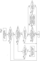
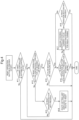
- the second steering controller 12 outputs the second target current value to the electric motor 31 based on processing of the flowcharts illustrated in FIGS. 2 , 4 .
- FIG. 2 is a flowchart when the left operation button 38L is operated.
- FIG. 4 is a flowchart when the right operation button 38R is operated.
- the steering controller 1 determines whether the first steering controller 11 is in the automatic control state (step #01). When the first steering controller 11 is in the non-control state (manual steering mode) (No in step #01), the processing based on the flowchart of FIG. 2 ends as it is. Then, the first steering controller 11 continuously outputs the first target current value to the electric motor 31.
- the steering controller 1 determines whether the left operation button 38L is continuously pressed for 0.5 seconds or more (step #02). When the left operation button 38L is not continuously pressed for 0.5 seconds or more (No in step #02), the steering controller 1 determines whether the left operation button 38L is not pressed (step #03).
- 0.5 seconds is an example of a "first setting time" of the present invention.
- the route setting unit 13 displaces the target route GL to the left by, for example, 5 to 10 centimeters without changing an extending direction of the target route GL (step #04).
- the navigation positioning device 35 uses the above-described DGPS, it is considered that the positioning error increases with the passage of time, and the target route GL is shifted to the right by an amount of the positioning error.
- the second steering controller 12 is configured not to control driving of the electric motor 31, and the route setting unit 13 is configured to displace the target route GL to the left without changing the extending direction of the target route GL. Then, the processing based on the flowchart of FIG. 2 is ended as it is, and the first steering controller 11 continuously outputs the first target current value to the electric motor 31.
- step #02 In a state where the left operation button 38L is not continuously pressed for 0.5 seconds or more (No in step #02), when the left operation button 38L is continuously pressed (No in step #03), the processing of step #02 and step #03 is repeated.
- step #02 the steering controller 1 determines whether the plow 6 is mounted on the traveling body of the tractor 5 based on the determination result of the determiner 14 (step #05).
- step #05 the processing based on the flowchart of FIG. 2 ends as it is.
- the first steering controller 11 continuously outputs the first target current value to the electric motor 31.
- the second steering controller 12 is configured to control driving of the electric motor 31 in a case where the plow 6 is mounted on the traveling body of the tractor 5, and is configured to be incapable of controlling driving of the electric motor 31 in a case where the plow 6 is not mounted on the traveling body of the tractor 5.
- the steering controller 1 determines whether the left operation button 38L is continuously pressed for 3 seconds or more (step #06). When the left operation button 38L is not continuously pressed for 3 seconds or more (No in step #06), the second steering controller 12 executes current value addition processing for left turning (step #07). In step #07, the second steering controller 12 outputs the second target current value to the electric motor 31 with priority over the first steering controller 11. In this case, the first steering controller 11 does not output the first target current value to the electric motor 31, and outputs only the second target current value to the electric motor 31.
- the second steering controller 12 is configured to control driving of the electric motor 31 with priority over the first steering controller 11 when the left operation button 38L is operated for a long time of 0.5 seconds or more.
- the second steering controller 12 controls driving of the electric motor 31 such that the steered wheel 5A is directed to the left side with respect to the steering direction based on the control of the first steering controller 11.
- the "current value addition processing for left turning” in a case where the right turning side is defined as addition and the left turning side is defined as subtraction, the "current value addition processing" may be rephrased as "current value subtraction processing".
- FIG. 3 illustrates a state where the plow 6 plows the agricultural field surface while the tractor 5 advances.
- the agricultural field surface after plowed by the plow 6 is illustrated as the plowed soil A1
- the agricultural field surface before plowed by the plow 6 is illustrated as an unplowed soil A2.
- the first steering controller 11 outputs the first target current value to the electric motor 31 such that the tractor 5 travels along the target route GL.
- the tractor 5 slips in the right direction (side on which the plowed soil A1 is located) as illustrated in a traveling trajectory FP.
- the operator operates the left operation button 38L at the point P1, and the second steering controller 12 executes the current value addition processing for left turning. Accordingly, even in a case where the steered wheel 5A of the tractor 5 is further steered to the left and a control gain of the first steering controller 11 is set gently, the tractor 5 is able to quickly return in the direction along the target route GL.
- step #08 When the left operation button 38L is not pressed (Yes in step #08), the processing based on the flowchart of FIG. 2 is ended as it is. Then, the first steering controller 11 outputs the first target current value to the electric motor 31 again.
- step #06, step #07, and step #08 are repeated.
- the processing based on the flowchart of FIG. 2 is ended as it is.
- the first steering controller 11 outputs the first target current value to the electric motor 31 again. That is, when the left operation button 38L is operated for a long time of 3 seconds or more, the second steering controller 12 is configured not to control driving of the electric motor 31, and the first steering controller 11 is configured to control driving of the electric motor 31.
- the 3 seconds is an example of a "second setting time" of the present invention.
- the flowchart of FIG. 4 is a flowchart in a case where the operator operates the right operation button 38R. Therefore, the processing of each step illustrated in the flowchart of FIG. 4 is the same as the processing of each step illustrated in FIG. 2 except for a difference between the left operation button 38L and the right operation button 38R, and a difference between left and right.
- the route setting unit 13 displaces the target route GL to the right by, for example, 5 to 10 centimeters. Accordingly, for example, in a case where the target route GL is shifted to the left by the amount of the positioning error of the navigation positioning device 35, the positional deviation of the target route GL in the left and right directions is eliminated.
- the second steering controller 12 is configured not to control driving of the electric motor 31, and the route setting unit 13 is configured to displace the target route GL to the right without changing the extending direction of the target route GL.
- step #17 the second steering controller 12 executes the current value addition processing for right turning.
- step #17 the second steering controller 12 outputs the second target current value to the electric motor 31 with priority over the first steering controller 11. That is, the second steering controller 12 is configured to control driving of the electric motor 31 with priority over the first steering controller 11 when the right operation button 38R is operated for a long time of 0.5 seconds or more. In this case, the second steering controller 12 controls driving of the electric motor 31 such that the steered wheel 5A is directed to the right with respect to the steering direction based on the control of the first steering controller 11.
- step #17 the first steering controller 11 does not output the first target current value to the electric motor 31, and outputs only the second target current value to the electric motor 31.
- step #16 when the right operation button 38R is operated for a long time of 3 seconds or more, the second steering controller 12 is configured not to control driving of the electric motor 31, and the first steering controller 11 is configured to control driving of the electric motor 31.
- the "current value addition processing for right turning” in a case where the left turning side is defined as addition and the right turning side is defined as subtraction, the "current value addition processing” may be rephrased as "current value subtraction processing”.
- FIG. 5 illustrates a state where the plow 6 plows the agricultural field surface while the tractor 5 advances.
- the agricultural field surface after plowed by the plow 6 is illustrated as the plowed soil A1
- the agricultural field surface before plowed by the plow 6 is illustrated as the unplowed soil A2.
- the first steering controller 11 outputs the first target current value to the electric motor 31 such that the tractor 5 travels along the target route GL, but as illustrated in the traveling trajectory FP, the tractor 5 slips in the left direction (side on which the plowed soil A1 is located).
- the operator operates the right operation button 38R at the point P1, and the second steering controller 12 executes the current value addition processing for right turning. Accordingly, even in a case where the steered wheel 5A of the tractor 5 is further steered to the right and the control gain of the first steering controller 11 is set gently, the tractor 5 is able to quickly return in the direction along the target route GL.
- the operator steers the steered wheel 5A to the unplowed soil A2 side by operating the left operation button 38L or the right operation button 38R. From this, for example, even in a case where the tractor 5 is likely to deviate significantly from the target route GL due to the slip, the operator is able to quickly return the tractor 5 to the target route GL by operating the left operation button 38L or the right operation button 38R.
- the first steering controller 11 when the operator operates the steering wheel 3A in a state where the first steering controller 11 is in the automatic control state, the first steering controller 11 changes the state from the automatic control state to the non-control state.
- the operator is able to quickly return the tractor 5 to the target route GL only by operating the left operation button 38L or the right operation button 38R without operating the steering wheel 3A. Then, the automatic control state of the first steering controller 11 continues as it is, and the tractor 5 travels along the target route GL.
- the operation tool 38 is used for both the displacement of the target route GL and the control by the second steering controller 12.
- the present invention is not limited to the configuration exemplified in the above-described embodiment, and representative different embodiments of the present invention will be described below.
- the present invention is able to be applied to an agricultural field work vehicle.
Landscapes
- Life Sciences & Earth Sciences (AREA)
- Engineering & Computer Science (AREA)
- Mechanical Engineering (AREA)
- Soil Sciences (AREA)
- Environmental Sciences (AREA)
- Guiding Agricultural Machines (AREA)
- Steering Control In Accordance With Driving Conditions (AREA)
- Control Of Position, Course, Altitude, Or Attitude Of Moving Bodies (AREA)
Abstract
An agricultural field work vehicle includes a traveling body including a steered wheel 5A, a steering mechanism 3 capable of steering the steered wheel 5A, and a steering drive device 31 capable of driving the steering mechanism 3 to operate; a route setting unit 13 configured to set a target route GL; a first steering controller 11 configured to change a state to an automatic control state where driving of the steering drive device 31 is controlled to travel along the target route GL and a non-control state where driving of the steering drive device 31 is not controlled; and a second steering controller 12 configured to control driving of the steering drive device 31 separately from the first steering controller 11 while maintaining the automatic control state in a case of the first steering controller 11 being in the automatic control state.
Description
- The present invention relates to an agricultural field work vehicle.
- For example, in an agricultural field work vehicle (in the literature, "work vehicle") disclosed in
Japanese Patent Application Laid-Open No. 2017-123804 - Patent Literature 1:
Japanese Patent Application Laid-Open No. 2017-123804 - By the way, in the agricultural field work vehicle disclosed in
Japanese Patent Application Laid-Open No. 2017-123804 Japanese Patent Application Laid-Open No. 2017-123804 - An object of the present invention is to provide an agricultural field work vehicle capable of executing further control while maintaining an automatic control state of a steering controller.
- An agricultural field work vehicle according to an aspect of the present invention includes a traveling body including a steered wheel, a steering mechanism capable of steering the steered wheel, and a steering drive device capable of driving the steering mechanism to operate; a route setting unit configured to set a target route; a first steering controller configured to change a state to an automatic control state where driving of the steering drive device is controlled to travel along the target route and a non-control state where driving of the steering drive device is not controlled; and a second steering controller configured to control driving of the steering drive device separately from the first steering controller while maintaining the automatic control state in a case of the first steering controller being in the automatic control state.
- According to the present invention, the second steering controller is provided in addition to the first steering controller capable of controlling driving of the steering drive device to travel along the target route. The second steering controller is configured to control driving of the steering drive device separately from the first steering controller while maintaining the automatic control state of the first steering controller. Therefore, even in a case where the traveling along the target route is not appropriately performed only by the control of the first steering controller, the second steering controller is able to control driving of the steering drive device separately as necessary. In this case, since the automatic control state of the first steering controller is maintained, when the agricultural field work vehicle returns to a state of traveling appropriately along the target route based on the control of the second steering controller, the control of the first steering controller based on the automatic control state is able to be continued as it is. As described above, according to the present invention, it is possible to realize an agricultural field work vehicle that is able to execute further control while maintaining the automatic control state of the steering controller.
- In the present invention, the first steering controller may be configured to output a first target command value to the steering drive device in the automatic control state, the first target command value being calculated to travel along the target route, and the second steering controller is configured to output a second target command value to the steering drive device, the second target command value being obtained by adding or subtracting a preset command value to or from the first target command value.
- According to the present configuration, the first steering controller is configured to output the target command value to the steering drive device. Therefore, the second steering controller is able to control the steering drive device as necessary only by calculating the target command value added or subtracted based on the target command value output by the first steering controller.
- In the present invention, the steering drive device may be an electric motor, and the first target command value and the second target command value may be current values, respectively.
- According to the present configuration, the steering drive device is the electric motor, and the first steering controller is configured to output the current value as the target command value to the electric motor. Therefore, the second steering controller is able to control the electric motor as necessary only by calculating the current value added or subtracted based on the current value output by the first steering controller.
- In the present invention, the second steering controller may be configured to control driving of the steering drive device in a case of a work device being mounted on the traveling body, and may be configured to be unable to control driving of the steering drive device in a case of the work device being not mounted on the traveling body.
- It is considered that the traveling along the target route may not be appropriately performed only by the control of the first steering controller due to work of the work device. According to the present configuration, the control by the second steering controller is able to be performed only when the work device is mounted. Accordingly, it is possible to limit the control by the second steering controller to a necessary agricultural field. In addition, by unintentionally performing the control by the second steering controller in the unnecessary agricultural field, a concern that the steering control is unstable is avoided.
- In the present invention, the agricultural field work vehicle may further include a determiner configured to determine whether the work device is mounted on the traveling body, in which the determiner may be configured to automatically detect the work device.
- With the present configuration, the configuration in which the control of the second steering controller is enabled in a case where the work device is mounted on the traveling body and the control of the second steering controller is disabled in a case where the work device is not mounted on the traveling body is easily realized by the automatic detection of the work device.
- In the present invention, the agricultural field work vehicle may further include an input unit configured to receive a manual operation; and a determiner configured to determine whether the work device is mounted on the traveling body, in which the determiner may be configured to detect the work device based on information input to the input unit by the manual operation.
- With the present configuration, the configuration in which the control of the second steering controller is enabled in a case where the work device is mounted on the traveling body and the control of the second steering controller is disabled in a case where the work device is not mounted on the traveling body is easily realized only by the manual operation on the input unit.
- In the present invention, the work device may be a plow.
- In a case where the work device is the plow, when the plow plows an agricultural field surface, the plow receives a reaction force in one direction of left and right from the agricultural field surface with respect to a traveling direction of the agricultural field work vehicle. Therefore, the agricultural field work vehicle tends to slip in the left and right directions. According to the present configuration, even in a case where the traveling along the target route is not appropriately performed only by the control of the first steering controller, the second steering controller is able to perform, for example, the control corresponding to the slip as necessary.
- In the present invention, the agricultural field work vehicle may further include an operation tool configured to receive a manual operation, in which the second steering controller may be configured to control driving of the steering drive device with priority over the first steering controller in a case of the first steering controller being in the automatic control state and the operation tool being operated.
- According to the present configuration, when an operator determines that the control by the second steering controller is required, the control by the second steering controller is realized only by operating the operation tool. Accordingly, the operator is able to easily perform the separately required control while maintaining the automatic control state of the first steering controller.
- In the present invention, the second steering controller may be configured not to control driving of the steering drive device and the first steering controller is configured to control driving of the steering drive device in a case of the first steering controller being in the automatic control state and the operation tool being not operated.
- According to the present configuration, when the operator determines that the control by the second steering controller is not necessary, the control by the first steering controller is performed as it is when the operator does not operate the operation tool. Accordingly, by unintentionally performing the control by the second steering controller in the unnecessary agricultural field, a concern that the steering control is unstable is avoided.
- In the present invention, the second steering controller may be configured to control driving of the steering drive device with priority over the first steering controller in a case of the operation tool being operated for a long time of a preset first setting time or more.
- According to the present configuration, in a case where the operator presses the operation tool for a long time of the first setting time or more, the control by the second steering controller is performed. Therefore, it is possible to confirm the intention of the operator to press the operation tool for a long time regarding whether to perform the control by the second steering controller.
- In the present invention, the second steering controller may be configured not to control driving of the steering drive device and the first steering controller may be configured to control driving of the steering drive device in a case of the operation tool being operated for a long time of a second setting time or more which is set to be longer than the first setting time.
- When the operation tool is pressed for a long time and the control by the second steering controller is performed for a long time, it is considered that the agricultural field work vehicle may excessively turn and the steering control may be unstable. According to the present configuration, when the operation tool is operated for a long time of the second setting time or more, the control of the second steering controller is ended. As a result, a concern that the steering control is unstable is reduced.
- In the present invention, the second steering controller may be configured not to control driving of the steering drive device, and the route setting unit may be configured to displace the target route to one of left and right without changing an extending direction of the target route in a case of the operation tool being operated for a short time of the first setting time or less.
- With the present configuration, the operation tool is also used as each operation tool for the displacement of the target route and the control by the second steering controller.
- In the present invention, the operation tool may include a first operation unit and a second operation unit, and the second steering controller may control driving of the steering drive device such that the steered wheel is directed to one of left and right with respect to a steering direction based on the control of the first steering controller in a case of the first operation unit being operated, and control driving of the steering drive device such that the steered wheel is directed to the other of left and right with respect to the steering direction based on the control of the first steering controller in a case of the second operation unit being operated.
- According to the present configuration, in a case where the operator wants to adjust the steering direction to any of left and right, the operator is able to quickly adjust the traveling direction of the agricultural field work vehicle by operating any of the first operation unit and the second operation unit.
-
-
FIG. 1 is a block diagram illustrating a steering controller; -
FIG. 2 is a flowchart illustrating processing in a case of a left operation button being operated; -
FIG. 3 is a diagram for describing current value addition processing for left turning performed by a second steering controller; -
FIG. 4 is a flowchart illustrating processing in a case of a right operation button being operated; and -
FIG. 5 is a diagram for describing current value addition processing for right turning performed by the second steering controller. - A steering controller 1 mounted on an agricultural field work vehicle will be described with reference to
FIG. 1 . The steering controller 1 may be a physical device such as a microcomputer or may be a combination of a device and software. Although not illustrated, the steering controller 1 includes a storage device. The storage device is, for example, a non-volatile memory (for example, a flash memory) or a ROM such as an EEPROM. The storage device stores data generated by each functional unit in the steering controller 1 primarily or constantly. - The steering controller 1 includes a
first steering controller 11, asecond steering controller 12, aroute setting unit 13, and adeterminer 14. Theroute setting unit 13 sets a target route GL that is a target of work traveling in a field. The work traveling refers to performing work on the field with a work device mounted on a traveling body while traveling. In the present embodiment, the target route GL is a linear route as illustrated inFIGS. 3 ,5 . The target route GL may be a route including a curve. - A detection value from a
current sensor 32, a calculation value from asteering angle calculator 34, a positioning signal from anavigation positioning device 35, and a detection value from aninertial measurement device 36 are input to thefirst steering controller 11. In addition, a target current value (target command value) is output from thefirst steering controller 11 to anelectric motor 31. Theelectric motor 31 is an example of an actuator for steering and corresponds to a "steering drive device" of the present invention. The target current value output from thefirst steering controller 11 to theelectric motor 31 is referred to as a "first target current value" in the present embodiment. The first target current value is an example of a "first target command value" of the present invention. Thesecond steering controller 12 will be described later. - The
electric motor 31 is operatively connected to asteering mechanism 3, and when theelectric motor 31 is driven, thesteering mechanism 3 is driven. In addition, thesteering mechanism 3 includes asteering wheel 3A, and thesteering wheel 3A receives a steering operation of the operator. - The
current sensor 32 detects an actual current value in theelectric motor 31. Amotor encoder 33 detects a rotation angle of theelectric motor 31. Themotor encoder 33 is configured to detect, for example, a rotation angle of theelectric motor 31 in a range of -10800 degrees to +10800 degrees. Themotor encoder 33 may be, for example, a resolver-type encoder or an optical encoder. - The
steering angle calculator 34 is configured to calculate a steering angle speed of a steeredwheel 5A (wheel, crawler, or the like) in the agricultural field work vehicle based on the detection value of themotor encoder 33. In addition, thesteering angle calculator 34 is configured to calculate the steering angle speed of the steeredwheel 5A in the agricultural field work vehicle based on an amount of change in the detection value of themotor encoder 33 per unit time. The steering angle speed of the steeredwheel 5A means a speed at which a direction of the steeredwheel 5A (disconnected angle of the steeredwheel 5A) changes. As the steering angle speed increases, the disconnected angle of the steeredwheel 5A changes more steeply. - The
navigation positioning device 35 receives a positioning signal from an artificial satellite (not illustrated) used in a global navigation satellite system (GNSS, for example, GPS, GLONASS, Galileo, QZSS, BeiDou, and the like). In the present embodiment, thenavigation positioning device 35 uses differential GPS (DGPS: relative positioning method), but real time kinematic GPS (RTK-GPS: interferometric positioning method) is able to also be used. - The
inertial measurement device 36 is, for example, a gyroaccelerometer or a magnetic orientation sensor, and detects an angular speed of a yaw angle of the agricultural field work vehicle and accelerations in three axis directions orthogonal to each other over time. Theinertial measurement device 36 is able to calculate the orientation change angle of the agricultural field work vehicle by integrating the angular speed. For this reason, measurement data measured by theinertial measurement device 36 includes data indicating the orientation (direction) of the agricultural field work vehicle. Although not described in detail, theinertial measurement device 36 is able to measure, in addition to the angular speed of the turning angle of the agricultural field work vehicle, the angular speed of right and left tilt angle of the agricultural field work vehicle, and forward and backward tilt angle of the agricultural field work vehicle, and the like. As described above, theinertial measurement device 36 detects the direction of a vehicle body of the agricultural field work vehicle. - The
first steering controller 11 calculates the position coordinates of the agricultural field work vehicle over time based on the positioning data output by thenavigation positioning device 35. Accordingly, thefirst steering controller 11 acquires the position coordinates of the agricultural field work vehicle. Further, thefirst steering controller 11 calculates a posture orientation of the agricultural field work vehicle based on the position coordinates of the agricultural field work vehicle and the detection value of theinertial measurement device 36. The posture orientation of the agricultural field work vehicle is an orientation in which the agricultural field work vehicle moves forward or backward while moving straight. - To describe with reference to
FIG. 3 , first, during the traveling of a tractor 5 which is an example of the agricultural field work vehicle, thefirst steering controller 11 calculates the initial posture orientation based on the current position coordinates of the tractor 5 and the position coordinates of the tractor 5 at a point where the tractor 5 has just traveled. Next, when the tractor 5 travels for a certain period of time after an initial posture orientation is calculated, thefirst steering controller 11 calculates a change amount of the orientation by performing integration processing on the angular speed detected by theinertial measurement device 36 during the traveling for the certain period of time. - Then, the
first steering controller 11 updates the calculation result of the orientation by adding the calculated change amount of the orientation to the initial posture orientation. Thereafter, the change amount in the posture orientation is similarly calculated every certain period of time, and the calculation result of the posture orientation is sequentially updated. With the above configuration, thefirst steering controller 11 calculates the orientation of the tractor 5. - The
steering mechanism 3 illustrated inFIG. 1 is a mechanism for steering the steeredwheel 5A of the tractor 5 in the form illustrated inFIG. 3 . Thefirst steering controller 11 is configured to control thesteering mechanism 3 to execute automatic steering of causing the tractor 5 to travel along the target route GL. As a control method of thefirst steering controller 11 with respect to thesteering mechanism 3, for example, known PID control is used. - The
first steering controller 11 has a plurality of control modes for controlling thesteering mechanism 3. This control mode is able to be switched between a plurality of modes including a manual steering mode that is a mode in which automatic steering is not executed and an automatic steering mode that is a mode in which automatic steering is executable. This control mode may be configured to be switchable by a manual operation, or may be configured to be automatically switchable. When the operator operates thesteering wheel 3A in a state where the control mode of thefirst steering controller 11 is the automatic steering mode, the control mode of thefirst steering controller 11 is switched to the manual steering mode. - When the control mode of the
first steering controller 11 is the manual steering mode, thefirst steering controller 11 does not output the first target current value to theelectric motor 31. In this case, the wheels or the crawlers of the agricultural field work vehicle are steered in accordance with the manual operation of thesteering wheel 3A in thesteering mechanism 3. Therefore, when the control mode of thefirst steering controller 11 is the manual steering mode, the state of thefirst steering controller 11 is a non-control state where the automatic steering is not performed. - When the control mode of the
first steering controller 11 is the automatic steering mode, thefirst steering controller 11 is configured to control to steer the agricultural field work vehicle such that the agricultural field work vehicle performs the automatic steering traveling along the target route GL based on the positioning data output by thenavigation positioning device 35 and the detection value by theinertial measurement device 36. - When the control mode of the
first steering controller 11 is the automatic steering mode, the state of thefirst steering controller 11 is an automatic control state where the automatic steering is performed. Therefore, thefirst steering controller 11 outputs the first target current value for the agricultural field work vehicle to travel along the target route GL in the automatic control state to theelectric motor 31. - As described above, the steering controller 1 is configured to change a state to a non-control state where automatic steering is not performed and an automatic control state where automatic steering is performed.
- As described above, the
first steering controller 11 outputs the first target current value for the agricultural field work vehicle to travel along the target route GL to theelectric motor 31 in the automatic control state. However, when the steeredwheel 5A or the like of the tractor 5 slips, there is a concern that the traveling direction of the tractor 5 may change significantly against the intention. In particular, in a case where the work device is a plow 6 (seeFIGS. 3 ,5 ), when theplow 6 plows an agricultural field surface, theplow 6 receives a reaction force in one direction of left and right from the agricultural field surface with respect to the traveling direction of the tractor 5. Therefore, the tractor 5 is likely to slip in the left and right directions. In addition, when thefirst steering controller 11 outputs the first target current value to theelectric motor 31, a control gain of thefirst steering controller 11 tends to be set gently in order to prevent the tractor 5 from making a sudden turn. In this state, for example, when the steeredwheel 5A or the like of the tractor 5 is fitted into a groove of a plowed soil A1 (seeFIGS. 3 ,5 ), there is a concern that the return may take time only with the automatic steering of thefirst steering controller 11. - In order to avoid such inconvenience, it is considered that the operator operates the
steering wheel 3A to return the tractor 5 to the target route GL before the steeredwheel 5A and the like are fitted into the groove of the plowed soil A1. However, as described above, when the operator operates thesteering wheel 3A in a state where thefirst steering controller 11 is in the automatic control state, thefirst steering controller 11 changes the state from the automatic control state to the non-control state. In this case, the operator is forced to perform troublesome work in order to return the state of thefirst steering controller 11 to the automatic control state. - In order to solve such a problem, in the present embodiment, the
second steering controller 12 is configured to control driving of theelectric motor 31 separately from thefirst steering controller 11 while maintaining the automatic control state of thefirst steering controller 11 when thefirst steering controller 11 is in the automatic control state. - The
second steering controller 12 is configured to be capable of adding or subtracting a preset current value to or from the first target current value output from thefirst steering controller 11. The target current value obtained by adding or subtracting to or from the first target current value output from thefirst steering controller 11 is referred to as a "second target current value" in the present embodiment. The second target current value is an example of a "second target command value" of the present invention. The determination result of thedeterminer 14 and a signal from anoperation tool 38 are input to thesecond steering controller 12. - An input signal from an
input unit 37 is input to thedeterminer 14. A three-point link mechanism (not illustrated) is provided at a rear portion of the traveling body of the tractor 5. Theinput unit 37 is configured to receive input of information related to the work device mounted on the three-point link mechanism. Thedeterminer 14 is configured to determine whether the work device is mounted on the traveling body of the tractor 5 based on the information input to theinput unit 37. - The
input unit 37 may be, for example, a communication port based on ISOBUS standard (international standard ISO 11783). In this case, thedeterminer 14 is configured to automatically detect the work device. - In addition, the
input unit 37 may be, for example, a touch panel-type operation screen display device mounted on the tractor 5, and may be configured to allow the operator to input the type of the work device by operating the operation screen display device. In this case, thedeterminer 14 is configured to detect the work device based on the information input to theinput unit 37 by the manual operation. - The
operation tool 38 is provided with aleft operation button 38L and aright operation button 38R. Each of theleft operation button 38L and theright operation button 38R is, for example, a seesaw-type press button switch biased to a neutral position. The condition for thesecond steering controller 12 to output the second target current value includes the operation of theleft operation button 38L or theright operation button 38R. That is, in a case where at least one of theleft operation button 38L and theright operation button 38R is operated when thefirst steering controller 11 is in the automatic control state, thesecond steering controller 12 is configured to control driving of theelectric motor 31 with priority over thefirst steering controller 11. In other words, in a case where neither theleft operation button 38L nor theright operation button 38R is operated when thefirst steering controller 11 is in the automatic control state, thesecond steering controller 12 is configured not to control driving of theelectric motor 31, and thefirst steering controller 11 is configured to control driving of theelectric motor 31. Theleft operation button 38L is an example of a "first operation unit" of the present invention. Theright operation button 38R is an example of a "second operation unit" of the present invention. - The
second steering controller 12 outputs the second target current value to theelectric motor 31 based on processing of the flowcharts illustrated inFIGS. 2 ,4 . -
FIG. 2 is a flowchart when theleft operation button 38L is operated.FIG. 4 is a flowchart when theright operation button 38R is operated. - The description will be made based on the flowchart of
FIG. 2 . When the operator presses theleft operation button 38L, first, the steering controller 1 determines whether thefirst steering controller 11 is in the automatic control state (step #01). When thefirst steering controller 11 is in the non-control state (manual steering mode) (No in step #01), the processing based on the flowchart ofFIG. 2 ends as it is. Then, thefirst steering controller 11 continuously outputs the first target current value to theelectric motor 31. - When the
first steering controller 11 is in the automatic control state (automatic steering mode) (Yes in step #01), the steering controller 1 determines whether theleft operation button 38L is continuously pressed for 0.5 seconds or more (step #02). When theleft operation button 38L is not continuously pressed for 0.5 seconds or more (No in step #02), the steering controller 1 determines whether theleft operation button 38L is not pressed (step #03). 0.5 seconds is an example of a "first setting time" of the present invention. - When the
left operation button 38L is not pressed within a time of less than 0.5 seconds (Yes in step #03), theroute setting unit 13 displaces the target route GL to the left by, for example, 5 to 10 centimeters without changing an extending direction of the target route GL (step #04). In a case where thenavigation positioning device 35 uses the above-described DGPS, it is considered that the positioning error increases with the passage of time, and the target route GL is shifted to the right by an amount of the positioning error. By shifting the target route GL to the left instep # 04 by theroute setting unit 13, the positional deviation of the target route GL in the left and right directions is eliminated. As described above, when theleft operation button 38L is operated for a short time of less than 0.5 seconds, thesecond steering controller 12 is configured not to control driving of theelectric motor 31, and theroute setting unit 13 is configured to displace the target route GL to the left without changing the extending direction of the target route GL. Then, the processing based on the flowchart ofFIG. 2 is ended as it is, and thefirst steering controller 11 continuously outputs the first target current value to theelectric motor 31. - In a state where the
left operation button 38L is not continuously pressed for 0.5 seconds or more (No in step #02), when theleft operation button 38L is continuously pressed (No in step #03), the processing ofstep # 02 andstep # 03 is repeated. - When the
left operation button 38L is continuously pressed for 0.5 seconds or more (Yes in step #02), the steering controller 1 determines whether theplow 6 is mounted on the traveling body of the tractor 5 based on the determination result of the determiner 14 (step #05). When theplow 6 is not mounted on the traveling body of the tractor 5 (No in step #05), the processing based on the flowchart ofFIG. 2 ends as it is. Then, thefirst steering controller 11 continuously outputs the first target current value to theelectric motor 31. That is, thesecond steering controller 12 is configured to control driving of theelectric motor 31 in a case where theplow 6 is mounted on the traveling body of the tractor 5, and is configured to be incapable of controlling driving of theelectric motor 31 in a case where theplow 6 is not mounted on the traveling body of the tractor 5. - When the
plow 6 is mounted on the traveling body of the tractor 5 (Yes in step #05), the steering controller 1 determines whether theleft operation button 38L is continuously pressed for 3 seconds or more (step #06). When theleft operation button 38L is not continuously pressed for 3 seconds or more (No in step #06), thesecond steering controller 12 executes current value addition processing for left turning (step #07). Instep # 07, thesecond steering controller 12 outputs the second target current value to theelectric motor 31 with priority over thefirst steering controller 11. In this case, thefirst steering controller 11 does not output the first target current value to theelectric motor 31, and outputs only the second target current value to theelectric motor 31. That is, thesecond steering controller 12 is configured to control driving of theelectric motor 31 with priority over thefirst steering controller 11 when theleft operation button 38L is operated for a long time of 0.5 seconds or more. In this case, thesecond steering controller 12 controls driving of theelectric motor 31 such that the steeredwheel 5A is directed to the left side with respect to the steering direction based on the control of thefirst steering controller 11. Regarding the "current value addition processing for left turning", in a case where the right turning side is defined as addition and the left turning side is defined as subtraction, the "current value addition processing" may be rephrased as "current value subtraction processing". -
FIG. 3 illustrates a state where theplow 6 plows the agricultural field surface while the tractor 5 advances. In the example illustrated inFIG. 3 , the agricultural field surface after plowed by theplow 6 is illustrated as the plowed soil A1, and the agricultural field surface before plowed by theplow 6 is illustrated as an unplowed soil A2. Thefirst steering controller 11 outputs the first target current value to theelectric motor 31 such that the tractor 5 travels along the target route GL. However, as described above, since theplow 6 receives a reaction force in one direction of left and right from the agricultural field surface, in the example illustrated inFIG. 3 , the tractor 5 slips in the right direction (side on which the plowed soil A1 is located) as illustrated in a traveling trajectory FP. Then, the operator operates theleft operation button 38L at the point P1, and thesecond steering controller 12 executes the current value addition processing for left turning. Accordingly, even in a case where the steeredwheel 5A of the tractor 5 is further steered to the left and a control gain of thefirst steering controller 11 is set gently, the tractor 5 is able to quickly return in the direction along the target route GL. - When the
left operation button 38L is not pressed (Yes in step #08), the processing based on the flowchart ofFIG. 2 is ended as it is. Then, thefirst steering controller 11 outputs the first target current value to theelectric motor 31 again. When theleft operation button 38L is continuously pressed in a state where three seconds have not elapsed after theleft operation button 38L is pressed (No in step #08),step # 06,step # 07, andstep # 08 are repeated. - When the
left operation button 38L is continuously pressed for 3 seconds or more (Yes in step #06), there is a concern that the tractor 5 may excessively turn. In this case as well, the processing based on the flowchart ofFIG. 2 is ended as it is. Then, thefirst steering controller 11 outputs the first target current value to theelectric motor 31 again. That is, when theleft operation button 38L is operated for a long time of 3 seconds or more, thesecond steering controller 12 is configured not to control driving of theelectric motor 31, and thefirst steering controller 11 is configured to control driving of theelectric motor 31. The 3 seconds is an example of a "second setting time" of the present invention. - The flowchart of
FIG. 4 is a flowchart in a case where the operator operates theright operation button 38R. Therefore, the processing of each step illustrated in the flowchart ofFIG. 4 is the same as the processing of each step illustrated inFIG. 2 except for a difference between theleft operation button 38L and theright operation button 38R, and a difference between left and right. - To supplement the flowchart of
FIG. 4 , instep # 14, theroute setting unit 13 displaces the target route GL to the right by, for example, 5 to 10 centimeters. Accordingly, for example, in a case where the target route GL is shifted to the left by the amount of the positioning error of thenavigation positioning device 35, the positional deviation of the target route GL in the left and right directions is eliminated. As described above, when theright operation button 38R is operated for a short time of less than 0.5 seconds, thesecond steering controller 12 is configured not to control driving of theelectric motor 31, and theroute setting unit 13 is configured to displace the target route GL to the right without changing the extending direction of the target route GL. - To supplement the flowchart of
FIG. 4 , instep # 17, thesecond steering controller 12 executes the current value addition processing for right turning. Instep # 17, thesecond steering controller 12 outputs the second target current value to theelectric motor 31 with priority over thefirst steering controller 11. That is, thesecond steering controller 12 is configured to control driving of theelectric motor 31 with priority over thefirst steering controller 11 when theright operation button 38R is operated for a long time of 0.5 seconds or more. In this case, thesecond steering controller 12 controls driving of theelectric motor 31 such that the steeredwheel 5A is directed to the right with respect to the steering direction based on the control of thefirst steering controller 11. In addition, instep # 17, thefirst steering controller 11 does not output the first target current value to theelectric motor 31, and outputs only the second target current value to theelectric motor 31. In addition, as illustrated instep # 16, when theright operation button 38R is operated for a long time of 3 seconds or more, thesecond steering controller 12 is configured not to control driving of theelectric motor 31, and thefirst steering controller 11 is configured to control driving of theelectric motor 31. Regarding the "current value addition processing for right turning", in a case where the left turning side is defined as addition and the right turning side is defined as subtraction, the "current value addition processing" may be rephrased as "current value subtraction processing". -
FIG. 5 illustrates a state where theplow 6 plows the agricultural field surface while the tractor 5 advances. In the example illustrated inFIG. 5 , the agricultural field surface after plowed by theplow 6 is illustrated as the plowed soil A1, and the agricultural field surface before plowed by theplow 6 is illustrated as the unplowed soil A2. In the example illustrated inFIG. 5 , thefirst steering controller 11 outputs the first target current value to theelectric motor 31 such that the tractor 5 travels along the target route GL, but as illustrated in the traveling trajectory FP, the tractor 5 slips in the left direction (side on which the plowed soil A1 is located). In this case, the operator operates theright operation button 38R at the point P1, and thesecond steering controller 12 executes the current value addition processing for right turning. Accordingly, even in a case where the steeredwheel 5A of the tractor 5 is further steered to the right and the control gain of thefirst steering controller 11 is set gently, the tractor 5 is able to quickly return in the direction along the target route GL. - In this way, for example, when the tractor 5 slips and is likely to fit into the groove on the plowed soil A1 side, the operator steers the steered
wheel 5A to the unplowed soil A2 side by operating theleft operation button 38L or theright operation button 38R. From this, for example, even in a case where the tractor 5 is likely to deviate significantly from the target route GL due to the slip, the operator is able to quickly return the tractor 5 to the target route GL by operating theleft operation button 38L or theright operation button 38R. - In addition, as described above, when the operator operates the
steering wheel 3A in a state where thefirst steering controller 11 is in the automatic control state, thefirst steering controller 11 changes the state from the automatic control state to the non-control state. In the present embodiment, the operator is able to quickly return the tractor 5 to the target route GL only by operating theleft operation button 38L or theright operation button 38R without operating thesteering wheel 3A. Then, the automatic control state of thefirst steering controller 11 continues as it is, and the tractor 5 travels along the target route GL. - Further, as illustrated in
FIGS. 2 ,4 , in the present embodiment, theoperation tool 38 is used for both the displacement of the target route GL and the control by thesecond steering controller 12. - The present invention is not limited to the configuration exemplified in the above-described embodiment, and representative different embodiments of the present invention will be described below.
- (1) The
electric motor 31 is illustrated as the "steering drive device" of the present invention. The steering drive device is not limited to the electric actuator exemplified by theelectric motor 31, and may be, for example, a hydraulic actuator such as a hydraulic motor or a hydraulic cylinder, or a hybrid actuator. The hybrid actuator is, for example, a hydraulic actuator or the like that drives a hydraulic pump with an electric servo motor. In a case where the steering drive device is the hydraulic motor, the hydraulic cylinder, or the like, the target command values (the first target command value and the second target command value) of the present invention may include, for example, an opening degree of a hydraulic valve with respect to the hydraulic motor, the hydraulic cylinder, or the like. In this case, the first target command value and the second target command value are command values related to the opening degree of the hydraulic valve. That is, thefirst steering controller 11 may be configured to output the first target command value calculated to travel along the target route GL to the steering drive device in the automatic control state, and thesecond steering controller 12 may be configured to output the second target command value obtained by adding or subtracting a command value set in advance to or from the first target command value to the steering drive device. - (2) In the above-described embodiment, the first setting time is set to 0.5 seconds, and the second setting time is set to 3 seconds. The present invention is not limited to this embodiment, and the first setting time and the second setting time is able to be appropriately changed to be set.
- (3) Each of the
left operation button 38L and theright operation button 38R may be, for example, a lever or a soft button displayed on a touch panel-type operation screen display device. In addition, theright operation button 38R may be the first operation unit, and theleft operation button 38L may be the second operation unit. In short, thesecond steering controller 12 may be configured to control driving of the electric motor 31 (steering drive device) such that the steeredwheel 5A is directed to one of left and right with respect to the steering direction based on the control of thefirst steering controller 11 when the first operation unit is operated, and to control driving of the electric motor 31 (steering drive device) such that the steeredwheel 5A is directed to the other of left and right with respect to the steering direction based on the control of thefirst steering controller 11 when the second operation unit is operated. - (4) In the above-described embodiment, the
operation tool 38 is used for both the displacement of the target route GL and the control by thesecond steering controller 12. The present invention is not limited to this embodiment, and for example, the displacement of the target route GL may be configured to be possible by operating another operation button. In this case, when theoperation tool 38 is operated, thesecond steering controller 12 may be configured to immediately output the second target current value (second target command value) to the electric motor 31 (steering drive device) without waiting for the long press of 0.5 seconds (first setting time). Alternatively, when theoperation tool 38 is operated, thesecond steering controller 12 may be configured to output the second target current value (second target command value) to the electric motor 31 (steering drive device) for a certain period of time set in advance from a timing at which the operator starts to press theoperation tool 38, regardless of whether the operator presses theoperation tool 38 for a long time. - (5) In the current value addition processing (
step # 07 and step #17) illustrated inFIGS. 2 ,4 , thesecond steering controller 12 outputs the second target current value (second target command value) to the electric motor 31 (steering drive device) with priority over thefirst steering controller 11. The present invention is not limited to this embodiment, and thesecond steering controller 12 may be configured to output the current value to the electric motor 31 (steering drive device) in parallel with thefirst steering controller 11. In this case, the second target current value (second target command value) may be an addition value or a subtraction value set in advance. A configuration may be adopted in which a total value of the first target current value (first target command value) calculated by thefirst steering controller 11 and the second target current value (second target command value) which is the addition value or the subtraction value is output to the electric motor 31 (steering drive device). - (6) The
first steering controller 11 controls driving of the electric motor 31 (steering drive device). The present invention is not limited thereto, and for example, thefirst steering controller 11 may also control the vehicle speed of the tractor 5. The agricultural field work vehicle may be configured to be capable of not only automatic steering but also automatic control of vehicle speed (including vehicle speed control in conjunction with control of the work device), automatic control of the work device, automatic turning control of the vehicle, automatic stop control of the vehicle, and the like. The automatic control of the work device includes, for example, automatic lifting and lowering control of the work device, automatic control of an angle (roll angle) of the work device, automatic control of a work width, automatic control of a work depth, automatic control of a scattering amount, automatic control of a seeding amount, automatic control of a fertilizing amount, and the like. - (7) In the above-described embodiment, the
plow 6 is exemplified as the work device. The present invention is not limited to this embodiment, and the work device may be, for example, a grass cutting device (boom mower, chopper, or the like), a mulcher, a stone picker, a seeding device, a rake, a tedder, a toward-type harvesting and sorting device, a pinching device, a tillage management device, or the like. - (8) In the above-described embodiment, the tractor 5 is exemplified as the agricultural field work vehicle, but the agricultural field work vehicle may be a rice transplanter, a harvester, a spreader, a mower, a tillage cultivator, or the like.
- In addition, the configuration disclosed in the above-described embodiment (including another embodiment, the same applies hereinafter) is able to be applied in combination with the configuration disclosed in another embodiment as long as there is no contradiction. In addition, the embodiments disclosed in the present specification are examples, and the embodiments of the present invention are not limited to these, and it is possible to appropriately modify the embodiments of the present invention within a range not departing from the object of the present invention.
- The present invention is able to be applied to an agricultural field work vehicle.
-
- 3: steering mechanism
- 5A: steered wheel
- 6: plow (work device)
- 11: first steering controller
- 12: second steering controller
- 13: route setting unit
- 14: determiner
- 31: electric motor (steering drive device)
- 37: input unit
- 38: operation tool
- 38L: left operation button (first operation unit)
- 38R: right operation button (second operation unit)
- GL: target route
Claims (13)
- An agricultural field work vehicle, comprising:a traveling body including a steered wheel, a steering mechanism capable of steering the steered wheel, and a steering drive device capable of driving the steering mechanism to operate;a route setting unit configured to set a target route;a first steering controller configured to change a state to an automatic control state where driving of the steering drive device is controlled to travel along the target route and a non-control state where driving of the steering drive device is not controlled; anda second steering controller configured to control driving of the steering drive device separately from the first steering controller while maintaining the automatic control state in a case of the first steering controller being in the automatic control state.
- The agricultural field work vehicle according to claim 1, wherein the first steering controller is configured to output a first target command value to the steering drive device in the automatic control state, the first target command value being calculated to travel along the target route, and
the second steering controller is configured to output a second target command value to the steering drive device, the second target command value being obtained by adding or subtracting a preset command value to or from the first target command value. - The agricultural field work vehicle according to claim 2, wherein the steering drive device is an electric motor, and
the first target command value and the second target command value are current values, respectively. - The agricultural field work vehicle according to any one of claims 1 to 3, wherein the second steering controller is configured to control driving of the steering drive device in a case of a work device being mounted on the traveling body, and is configured to be unable to control driving of the steering drive device in a case of the work device being not mounted on the traveling body.
- The agricultural field work vehicle according to claim 4, further comprising:a determiner configured to determine whether the work device is mounted on the traveling body,wherein the determiner is configured to automatically detect the work device.
- The agricultural field work vehicle according to claim 4, further comprising:an input unit configured to receive a manual operation; anda determiner configured to determine whether the work device is mounted on the traveling body,wherein the determiner is configured to detect the work device based on information input to the input unit by the manual operation.
- The agricultural field work vehicle according to any one of claims 4 to 6, wherein the work device is a plow.
- The agricultural field work vehicle according to any one of claims 1 to 7, further comprising:an operation tool configured to receive a manual operation,wherein the second steering controller is configured to control driving of the steering drive device with priority over the first steering controller in a case of the first steering controller being in the automatic control state and the operation tool being operated.
- The agricultural field work vehicle according to claim 8, wherein the second steering controller is configured not to control driving of the steering drive device and the first steering controller is configured to control driving of the steering drive device in a case of the first steering controller being in the automatic control state and the operation tool being not operated.
- The agricultural field work vehicle according to claim 8, wherein the second steering controller is configured to control driving of the steering drive device with priority over the first steering controller in a case of the operation tool being operated for a long time of a preset first setting time or more.
- The agricultural field work vehicle according to claim 10, wherein the second steering controller is configured not to control driving of the steering drive device and the first steering controller is configured to control driving of the steering drive device in a case of the operation tool being operated for a long time of a second setting time or more which is set to be longer than the first setting time.
- The agricultural field work vehicle according to claim 10 or 11, wherein the second steering controller is configured not to control driving of the steering drive device, and the route setting unit is configured to displace the target route to one of left and right without changing an extending direction of the target route in a case of the operation tool being operated for a short time of the first setting time or less.
- The agricultural field work vehicle according to any one of claims 8 to 12, wherein the operation tool includes a first operation unit and a second operation unit, and
the second steering controller controls driving of the steering drive device such that the steered wheel is directed to one of left and right with respect to a steering direction based on the control of the first steering controller in a case of the first operation unit being operated, and controls driving of the steering drive device such that the steered wheel is directed to the other of left and right with respect to the steering direction based on the control of the first steering controller in a case of the second operation unit being operated.
Applications Claiming Priority (2)
| Application Number | Priority Date | Filing Date | Title |
|---|---|---|---|
| JP2022096366A JP7717028B2 (en) | 2022-06-15 | 2022-06-15 | Field work vehicle |
| PCT/JP2023/021726 WO2023243597A1 (en) | 2022-06-15 | 2023-06-12 | Agricultural field work vehicle |
Publications (1)
| Publication Number | Publication Date |
|---|---|
| EP4541162A1 true EP4541162A1 (en) | 2025-04-23 |
Family
ID=89191292
Family Applications (1)
| Application Number | Title | Priority Date | Filing Date |
|---|---|---|---|
| EP23823887.7A Pending EP4541162A1 (en) | 2022-06-15 | 2023-06-12 | Agricultural field work vehicle |
Country Status (4)
| Country | Link |
|---|---|
| US (1) | US20250081874A1 (en) |
| EP (1) | EP4541162A1 (en) |
| JP (1) | JP7717028B2 (en) |
| WO (1) | WO2023243597A1 (en) |
Families Citing this family (1)
| Publication number | Priority date | Publication date | Assignee | Title |
|---|---|---|---|---|
| FR3122063B1 (en) * | 2021-04-22 | 2023-04-28 | Kuhn S A S | Method for adjusting and/or calibrating an agricultural machine |
Family Cites Families (17)
| Publication number | Priority date | Publication date | Assignee | Title |
|---|---|---|---|---|
| US20060167600A1 (en) * | 2005-01-27 | 2006-07-27 | Raven Industries, Inc. | Architecturally partitioned automatic steering system and method |
| FR2900285B1 (en) * | 2006-04-20 | 2012-08-10 | Pubert Henri Sas | MOTOCULTURE ELECTRICAL EQUIPMENT |
| US8700269B2 (en) * | 2011-03-08 | 2014-04-15 | Great Plains Manufacturing, Inc. | Steerable agricultural implement with multi-point hitch |
| CN103419650B (en) * | 2012-05-22 | 2016-03-30 | 比亚迪股份有限公司 | The power system of electronlmobil, electronlmobil and heating of battery method |
| US9709969B2 (en) * | 2013-03-15 | 2017-07-18 | Deere & Company | Methods and apparatus to control machine configurations |
| JP6260815B2 (en) | 2014-02-12 | 2018-01-17 | 株式会社ジェイテクト | Steering support device |
| US9439341B2 (en) * | 2014-08-08 | 2016-09-13 | Deere & Company | Multi-mode steering control for a vehicle |
| US9630318B2 (en) | 2014-10-02 | 2017-04-25 | Brain Corporation | Feature detection apparatus and methods for training of robotic navigation |
| JP6365332B2 (en) * | 2015-02-05 | 2018-08-01 | トヨタ自動車株式会社 | Vehicle control device |
| US9618938B2 (en) * | 2015-07-31 | 2017-04-11 | Ford Global Technologies, Llc | Field-based torque steering control |
| US11180189B2 (en) * | 2015-11-19 | 2021-11-23 | Agjunction Llc | Automated reverse implement parking |
| JP6552420B2 (en) | 2016-01-13 | 2019-07-31 | 株式会社クボタ | Work vehicle |
| JP6850759B2 (en) | 2018-03-27 | 2021-03-31 | ヤンマーパワーテクノロジー株式会社 | Autonomous steering device |
| JP7106418B2 (en) | 2018-10-04 | 2022-07-26 | 株式会社クボタ | work vehicle |
| US11338848B2 (en) * | 2019-02-20 | 2022-05-24 | Caterpillar Inc. | Alignment of steering controller angle and machine steering angle for transitioning between manual and autonomous operating modes |
| JP6766240B1 (en) * | 2019-09-06 | 2020-10-07 | 株式会社クボタ | Work vehicle |
| EP4028844B1 (en) * | 2019-09-09 | 2024-11-27 | Mtd Products Inc. | Real time kinematics power equipment device with auto-steering |
-
2022
- 2022-06-15 JP JP2022096366A patent/JP7717028B2/en active Active
-
2023
- 2023-06-12 WO PCT/JP2023/021726 patent/WO2023243597A1/en not_active Ceased
- 2023-06-12 EP EP23823887.7A patent/EP4541162A1/en active Pending
-
2024
- 2024-11-25 US US18/958,637 patent/US20250081874A1/en active Pending
Also Published As
| Publication number | Publication date |
|---|---|
| JP7717028B2 (en) | 2025-08-01 |
| JP2023183014A (en) | 2023-12-27 |
| WO2023243597A1 (en) | 2023-12-21 |
| US20250081874A1 (en) | 2025-03-13 |
Similar Documents
| Publication | Publication Date | Title |
|---|---|---|
| EP3822148B1 (en) | Work vehicle | |
| US9635798B2 (en) | Arrangement for automatically steering a combination of a self-propelled vehicle and an implement for cultivating a field | |
| EP4011185A1 (en) | Automatic travel system for work vehicle | |
| CN104603708B (en) | Agricultural automatic pilot and the method for guiding vehicle | |
| EP4068036B1 (en) | Autonomous travelling control system | |
| KR102709145B1 (en) | Travel working machine | |
| JP7290923B2 (en) | work vehicle | |
| US20250081874A1 (en) | Agricultural field work vehicle | |
| JP6809889B2 (en) | Work vehicle | |
| US20250212714A1 (en) | Work vehicle and method for controlling work vehicle | |
| JP2026031650A (en) | Field work vehicle | |
| JP6690518B2 (en) | Work vehicle | |
| EP3970464B1 (en) | Coupling device | |
| EP4079124B1 (en) | Work machine | |
| JP7106419B2 (en) | work vehicle | |
| EP3822149B1 (en) | Work vehicle | |
| JP7832909B2 (en) | Method for controlling work vehicles, control program for work vehicles, control system for work vehicles, and work system | |
| JP7161364B2 (en) | work vehicle | |
| JP6988972B2 (en) | Work vehicle | |
| JP7106418B2 (en) | work vehicle | |
| JP6788229B2 (en) | Automatic steering device for field work vehicles | |
| JP7832910B2 (en) | Method for controlling work vehicles, control program for work vehicles, control system for work vehicles, and work system | |
| JP2023151046A (en) | work vehicle | |
| WO2024135725A1 (en) | Work vehicle | |
| JP2022020811A (en) | Work vehicle |
Legal Events
| Date | Code | Title | Description |
|---|---|---|---|
| STAA | Information on the status of an ep patent application or granted ep patent |
Free format text: STATUS: THE INTERNATIONAL PUBLICATION HAS BEEN MADE |
|
| PUAI | Public reference made under article 153(3) epc to a published international application that has entered the european phase |
Free format text: ORIGINAL CODE: 0009012 |
|
| STAA | Information on the status of an ep patent application or granted ep patent |
Free format text: STATUS: REQUEST FOR EXAMINATION WAS MADE |
|
| 17P | Request for examination filed |
Effective date: 20241128 |
|
| AK | Designated contracting states |
Kind code of ref document: A1 Designated state(s): AL AT BE BG CH CY CZ DE DK EE ES FI FR GB GR HR HU IE IS IT LI LT LU LV MC ME MK MT NL NO PL PT RO RS SE SI SK SM TR |
|
| DAV | Request for validation of the european patent (deleted) | ||
| DAX | Request for extension of the european patent (deleted) |