EP4539531A1 - A method to shut down and restart radio units in open-ran cbrs networks - Google Patents
A method to shut down and restart radio units in open-ran cbrs networks Download PDFInfo
- Publication number
- EP4539531A1 EP4539531A1 EP24206198.4A EP24206198A EP4539531A1 EP 4539531 A1 EP4539531 A1 EP 4539531A1 EP 24206198 A EP24206198 A EP 24206198A EP 4539531 A1 EP4539531 A1 EP 4539531A1
- Authority
- EP
- European Patent Office
- Prior art keywords
- interface
- cima
- cms
- cdc
- alert
- Prior art date
- Legal status (The legal status is an assumption and is not a legal conclusion. Google has not performed a legal analysis and makes no representation as to the accuracy of the status listed.)
- Pending
Links
- 238000000034 method Methods 0.000 title claims description 25
- 238000001228 spectrum Methods 0.000 claims abstract description 49
- 238000012544 monitoring process Methods 0.000 claims abstract description 11
- 230000004044 response Effects 0.000 claims description 16
- 238000013475 authorization Methods 0.000 claims description 14
- 238000011084 recovery Methods 0.000 claims description 14
- 230000008859 change Effects 0.000 claims description 9
- 230000002045 lasting effect Effects 0.000 claims 6
- 230000006641 stabilisation Effects 0.000 claims 4
- 238000011105 stabilization Methods 0.000 claims 4
- 230000005540 biological transmission Effects 0.000 description 9
- 238000010586 diagram Methods 0.000 description 6
- 238000004891 communication Methods 0.000 description 5
- 230000005855 radiation Effects 0.000 description 4
- 241000070918 Cima Species 0.000 description 1
- 238000013459 approach Methods 0.000 description 1
- 230000002457 bidirectional effect Effects 0.000 description 1
- 230000001413 cellular effect Effects 0.000 description 1
- 238000001514 detection method Methods 0.000 description 1
- 238000005516 engineering process Methods 0.000 description 1
- 239000000463 material Substances 0.000 description 1
- 238000012986 modification Methods 0.000 description 1
- 230000004048 modification Effects 0.000 description 1
- 238000011176 pooling Methods 0.000 description 1
- 230000008569 process Effects 0.000 description 1
- 239000002699 waste material Substances 0.000 description 1
Images

Classifications
-
- H—ELECTRICITY
- H04—ELECTRIC COMMUNICATION TECHNIQUE
- H04W—WIRELESS COMMUNICATION NETWORKS
- H04W92/00—Interfaces specially adapted for wireless communication networks
- H04W92/04—Interfaces between hierarchically different network devices
- H04W92/045—Interfaces between hierarchically different network devices between access point and backbone network device
-
- H—ELECTRICITY
- H04—ELECTRIC COMMUNICATION TECHNIQUE
- H04W—WIRELESS COMMUNICATION NETWORKS
- H04W28/00—Network traffic management; Network resource management
- H04W28/02—Traffic management, e.g. flow control or congestion control
- H04W28/04—Error control
-
- H—ELECTRICITY
- H04—ELECTRIC COMMUNICATION TECHNIQUE
- H04L—TRANSMISSION OF DIGITAL INFORMATION, e.g. TELEGRAPHIC COMMUNICATION
- H04L41/00—Arrangements for maintenance, administration or management of data switching networks, e.g. of packet switching networks
- H04L41/06—Management of faults, events, alarms or notifications
- H04L41/0654—Management of faults, events, alarms or notifications using network fault recovery
- H04L41/0659—Management of faults, events, alarms or notifications using network fault recovery by isolating or reconfiguring faulty entities
- H04L41/0661—Management of faults, events, alarms or notifications using network fault recovery by isolating or reconfiguring faulty entities by reconfiguring faulty entities
-
- H—ELECTRICITY
- H04—ELECTRIC COMMUNICATION TECHNIQUE
- H04W—WIRELESS COMMUNICATION NETWORKS
- H04W24/00—Supervisory, monitoring or testing arrangements
- H04W24/04—Arrangements for maintaining operational condition
-
- H—ELECTRICITY
- H04—ELECTRIC COMMUNICATION TECHNIQUE
- H04W—WIRELESS COMMUNICATION NETWORKS
- H04W52/00—Power management, e.g. Transmission Power Control [TPC] or power classes
- H04W52/02—Power saving arrangements
- H04W52/0209—Power saving arrangements in terminal devices
- H04W52/0225—Power saving arrangements in terminal devices using monitoring of external events, e.g. the presence of a signal
- H04W52/0229—Power saving arrangements in terminal devices using monitoring of external events, e.g. the presence of a signal where the received signal is a wanted signal
- H04W52/0235—Power saving arrangements in terminal devices using monitoring of external events, e.g. the presence of a signal where the received signal is a wanted signal where the received signal is a power saving command
-
- H—ELECTRICITY
- H04—ELECTRIC COMMUNICATION TECHNIQUE
- H04W—WIRELESS COMMUNICATION NETWORKS
- H04W52/00—Power management, e.g. Transmission Power Control [TPC] or power classes
- H04W52/02—Power saving arrangements
- H04W52/0209—Power saving arrangements in terminal devices
- H04W52/0261—Power saving arrangements in terminal devices managing power supply demand, e.g. depending on battery level
- H04W52/0274—Power saving arrangements in terminal devices managing power supply demand, e.g. depending on battery level by switching on or off the equipment or parts thereof
- H04W52/028—Power saving arrangements in terminal devices managing power supply demand, e.g. depending on battery level by switching on or off the equipment or parts thereof switching on or off only a part of the equipment circuit blocks
-
- H—ELECTRICITY
- H04—ELECTRIC COMMUNICATION TECHNIQUE
- H04W—WIRELESS COMMUNICATION NETWORKS
- H04W88/00—Devices specially adapted for wireless communication networks, e.g. terminals, base stations or access point devices
- H04W88/08—Access point devices
- H04W88/085—Access point devices with remote components
-
- H—ELECTRICITY
- H04—ELECTRIC COMMUNICATION TECHNIQUE
- H04W—WIRELESS COMMUNICATION NETWORKS
- H04W24/00—Supervisory, monitoring or testing arrangements
- H04W24/02—Arrangements for optimising operational condition
-
- H—ELECTRICITY
- H04—ELECTRIC COMMUNICATION TECHNIQUE
- H04W—WIRELESS COMMUNICATION NETWORKS
- H04W76/00—Connection management
- H04W76/10—Connection setup
- H04W76/19—Connection re-establishment
-
- H—ELECTRICITY
- H04—ELECTRIC COMMUNICATION TECHNIQUE
- H04W—WIRELESS COMMUNICATION NETWORKS
- H04W88/00—Devices specially adapted for wireless communication networks, e.g. terminals, base stations or access point devices
- H04W88/18—Service support devices; Network management devices
Definitions
- the present disclosure is related to Open Radio Access Network (O-RAN) systems, and relates more particularly to O-RAN configuration for 4G and 5G citizens Broadband Radio Service (CBRS) networks.
- O-RAN Open Radio Access Network
- CBRS Citizens Broadband Radio Service
- CBRS citizens Broadband Radio Service
- FCC Federal Communications Commission
- IoT Internet of Things
- FIG. 1 which illustrates the CBRS architecture
- the spectrum is allocated and controlled by Spectrum Access System (SAS) 101.
- the CBRS devices (CBSD) 103 and Domain Proxy (DP) 102 have an interface (referenced as "WinnForum SAS-CBSD/DP Interface” in FIG. 1 ) with the SAS 101 for this function.
- the interface is defined by WinnForum standard.
- the CBRS spectrum is divided into three tiers: 1) Incumbent Access; 2) Priority Access License (PAL); and 3) General Authorized Access (GAA). Incumbent Access tier is reserved for the existing government and military users in the 3.5 GHz band.
- Priority Access License (PAL) tier which is designed for commercial users who have obtained a license for the frequency band, is used for large-scale wireless networks and high-speed broadband.
- General Authorized Access (GAA) tier which is available for unlicensed users who can access the frequency band on a non-interference basis, is designed for small-scale wireless networks and IoT devices.
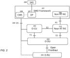
- the illustrated network functionalite is include Service Management and Orchestration (SMO) 201, O-RAN Central Unit (O-CU) 202, O-RAN Distributed Unit (O-DU) 203, O-RAN Radio Unit (O-RU) 204, O1 interface 205 connecting SMO 201 to O-CU 202, O-DU 203 and O-RU 204 (as well as other components which are not shown).
- SMO 201 which is a key element of the O-RAN architecture, provides a centralized platform for managing and orchestrating different network services.
- Cloud Management System (CMS) 206 is typically implemented in SMO 201 for management.
- CMS Cloud Management System
- DP 207 is typically located in the SMO 201 with a proprietary interface to CMS 206, as shown in FIG. 2 .
- DP 207 can also be part of CMS 206, or DP 207 can be part of Non-Real-Time Radio Intelligent Controller (Non-RT RIC) 209.
- Non-RT RIC Non-Real-Time Radio Intelligent Controller
- DP 207 has an external interface with SAS 208 shown in FIG. 2 .
- Near-RT RIC 210 is connected to each of Non-RT RIC 209, O-CU 202, and O-DU 203, via A1, E2 and E2 interfaces, respectively.
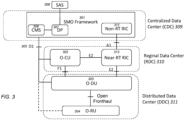
- the O1 interface 305 between CDC 309 and DDC 311 is considered an Operations and Management (O&M) interface, which is normally needed only for i) initial configuration of the radio cells (carrier served by O-RU), ii) any subsequent reconfigurations, and iii) for gathering the state information.
- O&M Operations and Management
- the cell operations can continue without any O&M connectivity because that connectivity is not needed to process any UE traffic. Therefore, the O1 interface does not need to be reliable, i.e., failure of the O1 interface will not impact the UE service.
- a CBRS O-RU deployed in an O-RAN-based CBRS network the following are implemented in the network: a centralized data center (CDC); multiple Distributed Data Centers (DDC's); CMS and DP located at the CDC; CBRS Interface Monitoring and Alert module located at the DDC (D-CIMA); at least one O-DU and multiple O-RUs located at each DDC, each DDC communicating with the CDC via an O1 interface.
- the D-CIMA alerts all associated O-DUs in the DDC so the O-DUs can shut down their O-RUs' transmission.
- the C-CIMA at the CDC alerts the status to the CMS and DP when the failure lasts more than specified Sc seconds threshold (this is for later recovery procedure).
- the C-CIMA at the CDC alerts CMS and DP of the recovery.
- the DP confirms the spectrum authorization and notifies the CMS, at which point the CMS sends restart instruction to the O-DUs only if the spectrum is still authorized.
- network includes both networks and internetworks of all kinds, including the Internet, and is not limited to any particular type of network or inter-network.
- first and second are used to distinguish one element, set, data, object or thing from another, and are not used to designate relative position or arrangement in time.
- Coupled means a relationship between or among two or more devices, apparatus, files, programs, applications, media, components, networks, systems, subsystems, and/or means, constituting any one or more of (a) a connection, whether direct or through one or more other devices, apparatus, files, programs, applications, media, components, networks, systems, subsystems, or means, (b) a communications relationship, whether direct or through one or more other devices, apparatus, files, programs, applications, media, components, networks, systems, subsystems, or means, and/or (c) a functional relationship in which the operation of any one or more devices, apparatus, files, programs, applications, media, components, networks, systems, subsystems, or means depends, in whole or in part, on the operation of any one or more others thereof.
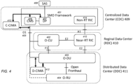
- O1 interface 405 connects CDC 409 to multiple DDCs 411 (only one is shown for the sake of clarity).
- the CDC 409 includes CMS 406 and DP 407.
- Each DDC contains at least one O-DU 403 (could be multiple O-Dus), and each O-DU 403 controls multiple ORUs 404 (only one is shown for the sake of clarity).
- Near-RT RIC 415 (of RDC 410) is connected to each of Non-RT RIC 414 (of CDC 409), O-CU 402 (of RDC 410), and O-DU 403 (of DDC 411), via A1, E2 and E2 interfaces, respectively.
- FIG. 4 additionally illustrates a D-CIMA 412 located in the DDC 411, which D-CIMA 412 monitors the O1 interface status.
- the monitoring service/functionality can be implemented according to ORAN Working Group 10 and 3GPP TS 28.537 standards, which rely on well-known heartbeat exchanges between two ends of the O1 interface (e.g., the implementation of the hearbeat exchange can use any open-source software, such as Bidirectional Forwarding Detection (BFD)), but the monitoring functionality is not deemed essential to the present disclosure.
- BFD Bidirectional Forwarding Detection
- each O-DU 403 manages multiple O-RUs 404 and can shut down or restart the transmission of the O-RUs 404.
- One D-CIMA 412 (located in DDC 411) can monitor multiple O1 Interfaces to each O-DU (if there are multiple O-DUs at the DDC).
- multiple D-CIMAs can be provided such that each D-CIMA monitors an associated O1 Interface for each O-DU. After the D-CIMA 412 detects a failure of O1 Interface for more than Sd seconds, D-CIMA 412 notifies all O-DUs 403 in the DDC 411 associated with the O1 Interface 405.
- each O-DU 403 shuts down or locks the O-RUs 404 to stop the O-RUs from radiating the signal.
- Sd is configurable based on the required time from the SAS 408 and the latency from the time the alert is generated to the time the shutdown is completed by the O-RU.
- a second CIMA, C-CIMA 413 located in CDC 409 also monitors the O1 Interface 405.
- the C-CIMA 413 detects a failure of O1 Interface 405 for more than Sc seconds, it notifies CMS 406 and DP 407 in CDC 409 to update the state change of the O1 Interface 405.
- Sc is configurable based on the required time from the SAS and the latency from the time the notification from the C-CIMA 413 is generated to the time the CMS 406 and DP 407 complete the state change.
- the C-CIMA 413 at the CDC 409 detects that O1 Interface 405 has recovered for more than Rc seconds
- the C-CIMA 413 alerts the CMS 406 of the recovery.
- the CMS 406 requests spectrum authorization status of the O-RU 404 from the DP 407. If the spectrum is still authorized, the CMS 406 sends a restart command to the O-DU 403, which in turn restarts the O-RU 404. If the spectrum is not authorized, the CMS 406 does not send the restart command to the O-DU 403, and the O-RU 404 remains in the shut-down state. If the spectrum has been changed by the SAS 408, the CMS 406 sends a new spectrum configuration and the restart command to the O-DU 404, which in turn applies the new spectrum configuration and restarts the O-RU 404.
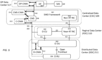
- CMS 506 is located at CDC 509, and DP 507 is located at DP Data Center 516, with an interface 516 connecting CMS 506 to DP 507.
- CMS-CIMA 514 (of CDC 509) and DP-CIMA 515 (of DP Data Center 516) are provided at the ends of the interface 516 connecting CMS 506 and DP 507, respectively.
- the CMS-CIMA 514 alerts the CMS 506 of the failure, and the CMS 506 will send a shutdown command to the O-DU 503 via the O1 interface 505.
- the O-DU 503 will shut down O-RU 504 signal radiation.
- Scm is configurable based on the required time from the SAS 508 and the latency from the time of the alert being generated by the CMS-CIMA 514 to the time the shutdown is completed by the O-RU 504.
- the DP-CIMA 515 (of DP Data Center 516) also monitor the interface 516 and sends an alert to the DP 507 after Sdp time period of continued failure of the interface 516.
- the DP 507 will update the status of the interface 516 to the CMS 506 and continue to exchange Heartbeat with the SAS 508.
- Sdp is configurable based on the required time from the SAS and the latency from the time the alert is generated by the DP-CIMA 515 to the time the DP 507 completes the state change.
- the DP-CIMA 515 observes that the interface 516 has recovered and has been stable for more than Rdp time period, the DP-CIMA 515 informs the DP 507 of the recovery.
- Rdp time period is configurable based on the required time to ensure the interface 516 is stable. If the spectrum is still authorized (which determination is made based on the heartbeat exchanged with the SAS 508 in the above step for determining the interface recovery), the DP 507 informs the CMS 506 of the spectrum authorization. The CMS 506 sends a restart command to the O-DU 503, which in turn restarts the O-RU 504. If the spectrum is not authorized, the O-RU 504 remains shut-down.
- the DP 507 can send a relinquishment of the spectrum to the SAS 508 so that the SAS 508 can allocate the spectrum to other CBSD users.
- the DP 507 can request a new spectrum (from the SAS).
- the DP 507 can retain the spectrum for the O-RU 504, but stop exchanging the Heartbeat messages with the SAS 508, thereby minimizing waste of resources on the Heartbeat. After both O1 interface 505 and the interface 516 recover, the DP 507 resumes the Heartbeat exchange with the SAS 508. After the SAS 508 confirms the spectrum is still authorized, the DP 507 notifies the CMS 506 of the spectrum authorization. The CMS 506 sends a restart command to the O-DU 503, which in turn restarts the O-RU 504.
Landscapes
- Engineering & Computer Science (AREA)
- Computer Networks & Wireless Communication (AREA)
- Signal Processing (AREA)
- Mobile Radio Communication Systems (AREA)
Abstract
A system for optimizing shut-down and restart of an Open Radio Access Network (O-RAN) radio unit (O-RU) deployed in an O-RAN Citizens Broadband Radio Service (CBRS) network includes: spectrum access system (SAS); CBRS Domain Proxy (DP) located in a Centralized Data Center (CDC); Cloud Management Service (CMS) located in the CDC; a first CBRS Interface Monitoring and Alert (CIMA) located in the CDC; a second CIMA located in a Distributed Data Center (DDC);at least one O-RAN Distributed Unit (O-DU) located in the DDC; a plurality of O-RAN Radio Units (O-RUs) located in the DDC; and an O1 interface connecting the CDC and DDC. The second CIMA located in the DDC monitors the O1 interface connection to the DDC, and if a failure of the O1 interface lasts longer than a specified time duration Sd, alerts the at least one O-DU regarding the failure of the O1 interface.
Description
- The present disclosure is related to Open Radio Access Network (O-RAN) systems, and relates more particularly to O-RAN configuration for 4G and 5G Citizens Broadband Radio Service (CBRS) networks.
- Citizens Broadband Radio Service (CBRS) is a wireless communication technology that operates in the 3.5 GHz band. CBRS was established by the Federal Communications Commission (FCC) in the United States to create a shared spectrum approach for wireless communication. CBRS is designed to support a wide range of applications, e.g., broadband access, Internet of Things (IoT) devices, and private wireless networks.
- As shown in
FIG. 1 , which illustrates the CBRS architecture, the spectrum is allocated and controlled by Spectrum Access System (SAS) 101. The CBRS devices (CBSD) 103 and Domain Proxy (DP) 102 have an interface (referenced as "WinnForum SAS-CBSD/DP Interface" inFIG. 1 ) with theSAS 101 for this function. The interface is defined by WinnForum standard. The CBRS spectrum is divided into three tiers: 1) Incumbent Access; 2) Priority Access License (PAL); and 3) General Authorized Access (GAA). Incumbent Access tier is reserved for the existing government and military users in the 3.5 GHz band. Priority Access License (PAL) tier, which is designed for commercial users who have obtained a license for the frequency band, is used for large-scale wireless networks and high-speed broadband. General Authorized Access (GAA) tier, which is available for unlicensed users who can access the frequency band on a non-interference basis, is designed for small-scale wireless networks and IoT devices. - As per FCC Rule Part 96 CBRS, CBRS requirements stipulate that if an Incumbent Access user (CBSD) would like to use the spectrum in a geographical area, the SAS will instruct PAL and GAA CBSDs to shut down their transmissions within 60 sec, and the SAS will subsequently instruct PAL and GAA CBSDs to resume once the Incumbent Access CBSD is not active anymore.
- In O-RAN networks (as well as in modern RAN networks), the network functionalities are split as illustrated in
FIG. 2 . The illustrated network functionaliteis include Service Management and Orchestration (SMO) 201, O-RAN Central Unit (O-CU) 202, O-RAN Distributed Unit (O-DU) 203, O-RAN Radio Unit (O-RU) 204,O1 interface 205 connectingSMO 201 to O-CU 202, O-DU 203 and O-RU 204 (as well as other components which are not shown). SMO 201, which is a key element of the O-RAN architecture, provides a centralized platform for managing and orchestrating different network services. Cloud Management System (CMS) 206 is typically implemented inSMO 201 for management. DP 207 is typically located in the SMO 201 with a proprietary interface toCMS 206, as shown inFIG. 2 . Alternatively, DP 207 can also be part of CMS 206, or DP 207 can be part of Non-Real-Time Radio Intelligent Controller (Non-RT RIC) 209. DP 207 has an external interface with SAS 208 shown inFIG. 2 . In addition, Near-RT RIC 210 is connected to each ofNon-RT RIC 209, O-CU 202, and O-DU 203, via A1, E2 and E2 interfaces, respectively. - As illustrated in
FIG. 3 , O-RAN components described above are typically placed in different geographical locations, connected by a transport interface forO1 interface 305, which can be a wireline or wireless, such as a microwave connection. As shown inFIG. 3 ,CMS 306 andDP 307 of the SMO 301, along with Non-RT RIC 312, are usually located in a centralized data center (CDC) 309. O-CU 302 can be at a reginal data center (RDC) 310 as shown, or alternatively at the CDC 309. O-DU 303 and O-RU 304 are at the Distributed Data Center (DDC) 311. There can be multiple O-DUs, each controlling multiple O-RUs. CDC 309, RDC 310 and DDC 311 can be considered as several O-Cloud in O-RAN terminology. In addition, Near-RT RIC 313 (of RDC 310) is connected to each of Non-RT RIC 312 (of CDC 309), O-CU 302 (of RDC 310), and O-DU 303 (of DDC 311), via A1, E2 and E2 interfaces, respectively. - The functionality of DP or CBSD can be implemented at the O-RU, but this implementation is not preferred because i) it will increase the cost of the radio and ii) the pooling of several CBSD to be served by a DP is complicated. Preferably, DP is used to represent CBSDs which are mapped to O-RUs, and DP is placed near CMS in the CDC. The functionality to shut down or restart O-RU transmission is performed by the O-DU.
- In typical O-RAN, e.g., as shown in
FIG. 3 , theO1 interface 305 between CDC 309 and DDC 311 is considered an Operations and Management (O&M) interface, which is normally needed only for i) initial configuration of the radio cells (carrier served by O-RU), ii) any subsequent reconfigurations, and iii) for gathering the state information. After the cell has been configured, the cell operations can continue without any O&M connectivity because that connectivity is not needed to process any UE traffic. Therefore, the O1 interface does not need to be reliable, i.e., failure of the O1 interface will not impact the UE service. However, a failure of the O1 interface creates a challenge in CBRS because, when the communication interface forO1 305 between the CDC 309 and the DDC 311 breaks, the O-DU 303 would lose contact with theDP 307. In this case, if the SAS 308 requests the CBSD (e.g., O-RU 304) to shut down its transmission, then the O-DU 303 cannot comply and the CBRS does not comply with FCC regulation. - One conventional solution in response to the O1 interface breaking is for the O-DU to shut down the O-RU transmission immediately. However, this solution is not ideal because the CBSD has 60 seconds to comply, and the interface could recover before 60 seconds expire. In addition, shutting down (or locking) the O-RU would mean service interruption as all UEs would be disconnected from the O-RU.
- If the O-RU has been shut down and the interface has recovered, one conventional solution is for the O-DU to restart the O-RU transmission immediately after the interface recovery. However, this solution is not ideal because the O-DU has been out of contact with the DP, and the SAS may have requested the DP to shut down the O-RU transmission. In this case, if the O-DU instructs the O-RU to restart the transmission without confirming with the DP first, then the CBSD does not comply with the FCC regulation.
- Accordingly, there is a need for a system and method for optimized implementation of shutting down and restarting radio units in Open-RAN CBRS networks.
- Accordingly, what is desired is a system and method to optimize implementation of shutting down and restarting radio units (e.g., O-RUs) in Open-RAN CBRS networks.
- According to an example system and method of the present disclosure, to shut down and restart signal radiation of a CBRS O-RU deployed in an O-RAN-based CBRS network, the following are implemented in the network: a centralized data center (CDC); multiple Distributed Data Centers (DDC's); CMS and DP located at the CDC; CBRS Interface Monitoring and Alert module located at the DDC (D-CIMA); at least one O-DU and multiple O-RUs located at each DDC, each DDC communicating with the CDC via an O1 interface. In the case the O1 interface fails and the failure lasts more than specified Sd seconds threshold, the D-CIMA alerts all associated O-DUs in the DDC so the O-DUs can shut down their O-RUs' transmission. The C-CIMA at the CDC alerts the status to the CMS and DP when the failure lasts more than specified Sc seconds threshold (this is for later recovery procedure). When the O1 interface is restored and stable for more than specified Rc time threshold, the C-CIMA at the CDC alerts CMS and DP of the recovery. The DP confirms the spectrum authorization and notifies the CMS, at which point the CMS sends restart instruction to the O-DUs only if the spectrum is still authorized.
- For this application, the following terms and definitions shall apply:
- The term "network" as used herein includes both networks and internetworks of all kinds, including the Internet, and is not limited to any particular type of network or inter-network.
- The terms "first" and "second" are used to distinguish one element, set, data, object or thing from another, and are not used to designate relative position or arrangement in time.
- The terms "coupled", "coupled to", "coupled with", "connected", "connected to", and "connected with" as used herein each mean a relationship between or among two or more devices, apparatus, files, programs, applications, media, components, networks, systems, subsystems, and/or means, constituting any one or more of (a) a connection, whether direct or through one or more other devices, apparatus, files, programs, applications, media, components, networks, systems, subsystems, or means, (b) a communications relationship, whether direct or through one or more other devices, apparatus, files, programs, applications, media, components, networks, systems, subsystems, or means, and/or (c) a functional relationship in which the operation of any one or more devices, apparatus, files, programs, applications, media, components, networks, systems, subsystems, or means depends, in whole or in part, on the operation of any one or more others thereof.
- The above-described and other features and advantages of the present disclosure will be appreciated and understood by those skilled in the art from the following detailed description, drawings, and appended claims.
-
-
FIG. 1 is a block diagram illustrating the CBRS architecture. -
FIG. 2 is a block diagram illustrating the O-RAN architecture with CMS and DP. -
FIG. 3 is a block diagram illustrating typical deployments of O-RAN components in different geographical locations. -
FIG. 4 is a block diagram illustrating various components of an example embodiment of a system and a method to shut down and restart signal radiation of an O-RU deployed in an O-RAN network. -
FIG. 5 is a block diagram illustrating various components of another example embodiment of a system and a method to shut down and restart signal radiation of an O-RU deployed in an O-RAN network. - In example embodiments of the system and method according to the present disclosure, optimized implementation of shutting down and restarting of a radio unit (e.g., O-RU) in O-RAN CBRS networks is provided. As shown in
FIG. 4 , which is a is a block diagram illustrating a first example embodiment,O1 interface 405 connectsCDC 409 to multiple DDCs 411 (only one is shown for the sake of clarity). TheCDC 409 includesCMS 406 andDP 407. Each DDC contains at least one O-DU 403 (could be multiple O-Dus), and each O-DU 403 controls multiple ORUs 404 (only one is shown for the sake of clarity). In addition, Near-RT RIC 415 (of RDC 410) is connected to each of Non-RT RIC 414 (of CDC 409), O-CU 402 (of RDC 410), and O-DU 403 (of DDC 411), via A1, E2 and E2 interfaces, respectively.FIG. 4 additionally illustrates a D-CIMA 412 located in theDDC 411, which D-CIMA 412 monitors the O1 interface status. The monitoring service/functionality can be implemented according to ORAN Working Group 10 and 3GPP TS 28.537 standards, which rely on well-known heartbeat exchanges between two ends of the O1 interface (e.g., the implementation of the hearbeat exchange can use any open-source software, such as Bidirectional Forwarding Detection (BFD)), but the monitoring functionality is not deemed essential to the present disclosure. - In the example embodiment shown in
FIG. 4 , each O-DU 403 manages multiple O-RUs 404 and can shut down or restart the transmission of the O-RUs 404. One D-CIMA 412 (located in DDC 411) can monitor multiple O1 Interfaces to each O-DU (if there are multiple O-DUs at the DDC). Alternatively, multiple D-CIMAs can be provided such that each D-CIMA monitors an associated O1 Interface for each O-DU. After the D-CIMA 412 detects a failure of O1 Interface for more than Sd seconds, D-CIMA 412 notifies all O-DUs 403 in theDDC 411 associated with theO1 Interface 405. In response to the notification, each O-DU 403 shuts down or locks the O-RUs 404 to stop the O-RUs from radiating the signal. Sd is configurable based on the required time from theSAS 408 and the latency from the time the alert is generated to the time the shutdown is completed by the O-RU. - In the example embodiment of
FIG. 4 , a second CIMA, C-CIMA 413 located inCDC 409, also monitors theO1 Interface 405. After the C-CIMA 413 detects a failure ofO1 Interface 405 for more than Sc seconds, it notifiesCMS 406 andDP 407 inCDC 409 to update the state change of theO1 Interface 405. Sc is configurable based on the required time from the SAS and the latency from the time the notification from the C-CIMA 413 is generated to the time theCMS 406 andDP 407 complete the state change. - After the C-
CIMA 413 at theCDC 409 detects thatO1 Interface 405 has recovered for more than Rc seconds, the C-CIMA 413 alerts theCMS 406 of the recovery. In response, theCMS 406 requests spectrum authorization status of the O-RU 404 from theDP 407. If the spectrum is still authorized, theCMS 406 sends a restart command to the O-DU 403, which in turn restarts the O-RU 404. If the spectrum is not authorized, theCMS 406 does not send the restart command to the O-DU 403, and the O-RU 404 remains in the shut-down state. If the spectrum has been changed by theSAS 408, theCMS 406 sends a new spectrum configuration and the restart command to the O-DU 404, which in turn applies the new spectrum configuration and restarts the O-RU 404. - According to another example embodiment illustrated in
FIG. 5 ,CMS 506 is located atCDC 509, andDP 507 is located atDP Data Center 516, with aninterface 516 connectingCMS 506 toDP 507. In this case, CMS-CIMA 514 (of CDC 509) and DP-CIMA 515 (of DP Data Center 516) are provided at the ends of theinterface 516 connectingCMS 506 andDP 507, respectively. If theinterface 516 fails for more than threshold Scm time period, the CMS-CIMA 514 alerts theCMS 506 of the failure, and theCMS 506 will send a shutdown command to the O-DU 503 via theO1 interface 505. In response to the shutdown command, the O-DU 503 will shut down O-RU 504 signal radiation. Scm is configurable based on the required time from theSAS 508 and the latency from the time of the alert being generated by the CMS-CIMA 514 to the time the shutdown is completed by the O-RU 504. - In the example embodiment of
FIG. 5 , the DP-CIMA 515 (of DP Data Center 516) also monitor theinterface 516 and sends an alert to theDP 507 after Sdp time period of continued failure of theinterface 516. TheDP 507 will update the status of theinterface 516 to theCMS 506 and continue to exchange Heartbeat with theSAS 508. Sdp is configurable based on the required time from the SAS and the latency from the time the alert is generated by the DP-CIMA 515 to the time theDP 507 completes the state change. When the DP-CIMA 515 observes that theinterface 516 has recovered and has been stable for more than Rdp time period, the DP-CIMA 515 informs theDP 507 of the recovery. Rdp time period is configurable based on the required time to ensure theinterface 516 is stable. If the spectrum is still authorized (which determination is made based on the heartbeat exchanged with theSAS 508 in the above step for determining the interface recovery), theDP 507 informs theCMS 506 of the spectrum authorization. TheCMS 506 sends a restart command to the O-DU 503, which in turn restarts the O-RU 504. If the spectrum is not authorized, the O-RU 504 remains shut-down. - In the example embodiment shown in
FIG. 5 , if either theO1 interface 505 or theinterface 516 between theCMS 506 and theDP 507 remains in the failed state for an extended period of time (e.g., exceeding a specified threshold duration), theDP 507 can send a relinquishment of the spectrum to theSAS 508 so that theSAS 508 can allocate the spectrum to other CBSD users. When theinterface 516 between theCMS 506 and theDP 507 has been restored, theDP 507 can request a new spectrum (from the SAS). Alternatively, if either theO1 interface 505 or theinterface 516 remains in the failed state for an extended period of time, theDP 507 can retain the spectrum for the O-RU 504, but stop exchanging the Heartbeat messages with theSAS 508, thereby minimizing waste of resources on the Heartbeat. After bothO1 interface 505 and theinterface 516 recover, theDP 507 resumes the Heartbeat exchange with theSAS 508. After theSAS 508 confirms the spectrum is still authorized, theDP 507 notifies theCMS 506 of the spectrum authorization. TheCMS 506 sends a restart command to the O-DU 503, which in turn restarts the O-RU 504. - While the present disclosure has been described with reference to one or more exemplary embodiments, it will be understood by those skilled in the art that various changes may be made and equivalents may be substituted for elements thereof without departing from the scope of the present disclosure. For example, although the example methods have been described in the context of 5G cellular networks, the example methods are equally applicable for 6G and other similar wireless networks in which BWP concept is applicable. In addition, many modifications may be made to adapt a particular situation or material to the teachings of the disclosure without departing from the scope thereof. Therefore, it is intended that the present disclosure not be limited to the particular embodiment(s) disclosed as the best mode contemplated, but that the disclosure will include all embodiments falling within the scope of the appended claims.
Claims (16)
- A system for optimizing at least one of shut-down and restart of an Open Radio Access Network (O-RAN) radio unit (O-RU) deployed in an O-RAN Citizens Broadband Radio Service (CBRS) network serving at least one CBRS device (CBSD), comprising:spectrum access system (SAS);CBRS Domain Proxy (DP) located in a Centralized Data Center (CDC);Cloud Management Service (CMS);a first CBRS Interface Monitoring and Alert (CIMA) located in the CDC;a second CIMA located in a Distributed Data Center (DDC);at least one O-RAN Distributed Unit (O-DU) located in the DDC;a plurality of O-RAN Radio Units (O-RUs) located in the DDC; andan O1 interface connecting the CDC and DDC;wherein:i) the second CIMA located in the DDC is configured to monitor the O1 interface connection to the DDC, and in the case a failure of the O1 interface lasting longer than a specified time duration Sd is detected, alert the at least one O-DU regarding the failure of the O1 interface; andii) in response to the alert from the second CIMA, the at least one O-DU shuts down the plurality of O-RUs.
- The system of claim 1, wherein the time duration Sd is specified based on i) a required time dictated by the SAS, and ii) an expected latency from the time the alert from the second CIMA is generated to the time when shut-down of the O-RUs is completed.
- The system of claim 2, wherein:i) the DP is located in the CDC; andii) the first CIMA located in the CDC is configured to monitor the O1 interface connection to the DDC, and in the case a failure of the O1 interface lasting longer than a specified time duration Sc is detected, alert the CMS and the DP to update change of state of the O-RUs, and wherein SC is specified based on i) a required time dictated by the SAS, and ii) an expected latency from the time the alert from the first CIMA is generated to the time when the CMS and the DP complete the update of the change of state of the O-RUs.
- The system of claim 1,wherein the CMS is located in the CDC, and wherein a restart procedure for the O-RUs is implemented by at least the first CIMA located in the CDC and the CMS as follows:i) the first CIMA located in the CDC is configured to monitor the O1 interface connection to the DDC, and in the case a recovery of the O1 interface lasting more than a specified time duration Rc is detected, alert the CMS of the O1 interface recovery, wherein Rc is specified based on a required time to ensure stabilization of the O1 interface;ii) the CMS is configured to request spectrum authorization status for the O-RU from the DP; and
one of:iii) in the case spectrum authorization is still valid, the CMS is configured to send a restart command to the O-DU to restart the O-RUs; oriv) in the case of change of spectrum by the SAS, the CMS is configured to send a new spectrum configuration and the restart command to the O-DU, whereby the O-DU applies the new configuration and restarts the O-RUs. - The system of claim 1, further comprising:a third CIMA located in the CDC; anda fourth CIMA located in a DP data center distinct from the CDC;wherein:i) the CMS is located in the CDC, and the DP is located in the DP data center, with a second interface connecting the CMS and the DP;ii) the third CIMA located in the CDC is configured to monitor the second interface, and in the case the second interface fails for a duration exceeding a specified time duration Scm, alert the CMS of the failure of the second interface, wherein Scm is specified based on a required time dictated by the SAS and an expected latency from the time the alert from the third CIMA is generated to the time when shut-down of the O-RUs is completed;iii) in response to the alert from the third CIMA, the CMS in configured to send a shut-down command to the O-DU via the O1 interface; andiv) in response to the shut-down command, the O-DU shuts down the O-RUs.
- The system of claim 5, wherein:the fourth CIMA located in the DP data center is configured to monitor the second interface, and in the case the second interface fails for a duration exceeding a specified time duration Sdp, alert the DP of the failure of the second interface, wherein Sdp is specified based on a required time dictated by the SAS and an expected latency from the time the alert from the fourth CIMA is generated to the time when the DP completes an update of status of the second interface; andin response to the alert from the fourth CIMA, the DP is configured to update the status of the second interface and continue to exchange heartbeats with the SAS to keep spectrum grant authorized.
- The system of claim 6, wherein:in the case the fourth CIMA located in the DP data center detects recovery of the second interface for a duration exceeding a specified time duration Rdp, the fourth CIMA is configured to alert the DP of the recovery, wherein Rdp is specified based on a time duration to ensure stabilization of the second interface; andin the case spectrum authorization is still valid, the DP is configured to notify the CMS of the spectrum authorization;in response to the spectrum authorization notification, the CMS is configured to send a restart command to the O-DU to restart the O-RUs.
- The system of claim 5, wherein:in the case one of the failure of the O1 interface or the failure of the second interface exceeds a specified threshold for an extended period of time, the DP is configured to send a relinquishment of spectrum notification to the SAS;in response to the relinquishment of spectrum notification, the SAS is configured to reallocate the spectrum from an original CBSD to a different CBSD; andin the case the second interface is subsequently recovered, the DP is configured to request a new spectrum from the SAS.
- A method for optimizing at least one of shut-down and restart of an Open Radio Access Network (O-RAN) radio unit (O-RU) deployed in an O-RAN Citizens Broadband Radio Service (CBRS) network serving at least one CBRS device (CBSD), said O-RAN CBRS network comprising a spectrum access system (SAS), a CBRS Domain Proxy (DP) located in a Centralized Data Center (CDC), a Cloud Management Service (CMS), a first CBRS Interface Monitoring and Alert (CIMA) located in the CDC, a second CIMA located in a Distributed Data Center (DDC), at least one O-RAN Distributed Unit (O-DU) located in the DDC, a plurality of O-RAN Radio Units (O-RUs) located in the DDC, and an O1 interface connecting the CDC and DDC, the method comprising:monitoring, by the second CIMA located in the DDC, the O1 interface connection to the DDC;in the case a failure of the O1 interface lasting longer than a specified time duration Sd is detected, sending by the second CIMA to the at least one O-DU an alert regarding the failure of the O1 interface; andshutting down, by the at least one O-DU, the plurality of O-RUs in response to the alert from the second CIMA.
- The method of claim 9, wherein the time duration Sd is specified based on i) a required time dictated by the SAS, and ii) an expected latency from the time the alert from the second CIMA is generated to the time when shut-down of the O-RUs is completed.
- The method of claim 10, wherein the DP is located in the CDC, and the method further comprising:monitoring, by the first CIMA located in the CDC, the O1 interface connection to the DDC; andin the case a failure of the O1 interface lasting longer than a specified time duration Sc is detected, sending by the first CIMA located in the CDS an alert to the CMS and the DP to update change of state of the O-RUs;wherein Sc is specified based on i) a required time dictated by the SAS, and ii) an expected latency from the time the alert from the first CIMA is generated to the time when the CMS and the DP complete the update of the change of state of the O-RUs.
- The method of claim 9, wherein the CMS is located in the CDC, and the method further comprising:
implementing a restart procedure for the O-RUs by at least the first CIMA located in the CDC and the CMS as follows:i) monitoring, by the first CIMA located in the CDC, the O1 interface connection to the DDC, and in the case a recovery of the O1 interface lasting more than a specified time duration Rc is detected, alerting the CMS of the O1 interface recovery, wherein Rc is specified based on a required time to ensure stabilization of the O1 interface;ii) requesting, by the CMS, spectrum authorization status for the O-RU from the DP; and one of:iii) in the case spectrum authorization is still valid, sending by the CMS a restart command to the O-DU to restart the O-RUs; oriv) in the case of change of spectrum by the SAS, sending by the CMS a new spectrum configuration and the restart command to the O-DU, whereby the O-DU applies the new configuration and restarts the O-RUs. - The method of claim 9, wherein a third CIMA located in the CDC is provided, a fourth CIMA located in a DP data center distinct from the CDC is provided, the CMS is located in the CDC, and the DP is located in the DP data center, with a second interface connecting the CMS and the DP, and the method further comprising:monitoring, by the third CIMA located in the CDC, the second interface, and in the case the second interface fails for a duration exceeding a specified time duration Scm, alerting the CMS of the failure of the second interface, wherein Scm is specified based on a required time dictated by the SAS and an expected latency from the time the alert from the third CIMA is generated to the time when shut-down of the O-RUs is completed;in response to the alert from the third CIMA, sending by the CMS a shut-down command to the O-DU via the O1 interface; andin response to the shut-down command, shutting down the O-RUs by the O-DU.
- The method of claim 13, further comprising:monitoring, by the fourth CIMA located in the DP data center, the second interface, and in the case the second interface fails for a duration exceeding a specified time duration Sdp, alerting the DP of the failure of the second interface, wherein Sdp is specified based on a required time dictated by the SAS and an expected latency from the time the alert from the fourth CIMA is generated to the time when the DP completes an update of status of the second interface; andin response to the alert from the fourth CIMA, performing the following by the DP: i) updating the status of the second interface; and ii) exchanging heartbeats with the SAS to keep spectrum grant authorized.
- The method of claim 14, further comprising:in the case the fourth CIMA located in the DP data center detects recovery of the second interface for a duration exceeding a specified time duration Rdp, alerting the DP of the recovery by the fourth CIMA, wherein Rdp is specified based on a time duration to ensure stabilization of the second interface;in the case spectrum authorization is still valid, notifying the CMS of the spectrum authorization by the DP; andin response to the spectrum authorization notification, sending a restart command to the O-DU by the CMS to restart the O-RUs.
- The method of claim 13, further comprising:in the case one of the failure of the O1 interface or the failure of the second interface exceeds a specified threshold for an extended period of time, sending by the DP a relinquishment of spectrum notification to the SAS;in response to the relinquishment of spectrum notification, reallocating the spectrum from an original CBSD to a different CBSD by the SAS; andin the case the second interface is subsequently recovered, requesting by the DP a new spectrum from the SAS.
Applications Claiming Priority (2)
| Application Number | Priority Date | Filing Date | Title |
|---|---|---|---|
| US202363590113P | 2023-10-13 | 2023-10-13 | |
| US18/907,799 US20250126516A1 (en) | 2023-10-13 | 2024-10-07 | Method to shut down and restart radio units in open-ran cbrs networks |
Publications (1)
| Publication Number | Publication Date |
|---|---|
| EP4539531A1 true EP4539531A1 (en) | 2025-04-16 |
Family
ID=93117276
Family Applications (1)
| Application Number | Title | Priority Date | Filing Date |
|---|---|---|---|
| EP24206198.4A Pending EP4539531A1 (en) | 2023-10-13 | 2024-10-11 | A method to shut down and restart radio units in open-ran cbrs networks |
Country Status (2)
| Country | Link |
|---|---|
| US (1) | US20250126516A1 (en) |
| EP (1) | EP4539531A1 (en) |
Citations (3)
| Publication number | Priority date | Publication date | Assignee | Title |
|---|---|---|---|---|
| US20210352488A1 (en) * | 2018-09-07 | 2021-11-11 | Nokia Solutions And Networks Oy | A highly available radio access network in a shared spectrum |
| US20230040563A1 (en) * | 2021-06-23 | 2023-02-09 | Mavenir Systems, Inc. | Supporting cbrs operation using non-real time ran intelligent controller (non-rt ric) applications |
| JP2023144649A (en) * | 2022-03-28 | 2023-10-11 | Kddi株式会社 | Communication devices, monitoring devices, control methods, and programs that make O-RAN operations more efficient |
-
2024
- 2024-10-07 US US18/907,799 patent/US20250126516A1/en active Pending
- 2024-10-11 EP EP24206198.4A patent/EP4539531A1/en active Pending
Patent Citations (3)
| Publication number | Priority date | Publication date | Assignee | Title |
|---|---|---|---|---|
| US20210352488A1 (en) * | 2018-09-07 | 2021-11-11 | Nokia Solutions And Networks Oy | A highly available radio access network in a shared spectrum |
| US20230040563A1 (en) * | 2021-06-23 | 2023-02-09 | Mavenir Systems, Inc. | Supporting cbrs operation using non-real time ran intelligent controller (non-rt ric) applications |
| JP2023144649A (en) * | 2022-03-28 | 2023-10-11 | Kddi株式会社 | Communication devices, monitoring devices, control methods, and programs that make O-RAN operations more efficient |
Non-Patent Citations (1)
| Title |
|---|
| "Publicly Available Specification (PAS); O-RAN Fronthaul Control, User and Synchronization Plane Specification v7.01- Nov 2021(ORAN-WG4.CUS.0-v07.01)", no. V0.0.2, 2 May 2022 (2022-05-02), pages 1 - 309, XP014432870, Retrieved from the Internet <URL:ftp://docbox.etsi.org/MSG/MSG/70-Draft/001140/MSG-001140v002.docx> [retrieved on 20220502] * |
Also Published As
| Publication number | Publication date |
|---|---|
| US20250126516A1 (en) | 2025-04-17 |
Similar Documents
| Publication | Publication Date | Title |
|---|---|---|
| US11323931B2 (en) | Communication method and apparatus for a terminal device moving from a first access node to a second access node | |
| RU2495548C2 (en) | Method, device and mobile communication system for providing uninterrupted service | |
| EP2064906B1 (en) | Method for recovering connectivity in the event of a failure in a radio communications system and controlling node thereof | |
| EP2525620B1 (en) | Method, device and communication system for dormancy timer control | |
| WO2018045877A1 (en) | Network slicing control method and related device | |
| KR20220133187A (en) | Method and apparatus for reporting failure of data transmission procedure for network optimization in wireless communication system | |
| EP3422795B1 (en) | Basic service set identifier (bssid) updating | |
| WO2020175906A1 (en) | Mobility condition change based on serving cell quality and connection release | |
| JP2025504891A (en) | Communication related to network slices | |
| EP3979690B1 (en) | Congestion control method and apparatus, computer storage medium and terminal | |
| EP2675196A1 (en) | Method for processing content network information, base station and content network system | |
| CN112399455B (en) | Lora gateway control method and Lora communication system | |
| US9843491B2 (en) | Network element in network management system, network management system, and network management method | |
| EP3841838B1 (en) | System and method for creating and managing private subnetworks of lte base stations | |
| EP3921998B1 (en) | Migration of computational service | |
| US20250126516A1 (en) | Method to shut down and restart radio units in open-ran cbrs networks | |
| US12058603B2 (en) | Systems and methods for preventing undesired access barring alleviation | |
| KR102939927B1 (en) | NF device and signaling control method performed in NF | |
| US20240430674A1 (en) | Communication related to use report | |
| CN114510247B (en) | Service deployment method, system and device for multi-access edge computing device | |
| CN116132855B (en) | Ring network protection method, device, electronic equipment and storage medium | |
| CN105072185A (en) | TR069 (Technical Report 069) remote monitoring method and system, and communication equipment | |
| CN107708212A (en) | The collocation method and device that chain rupture is held time | |
| EP2292036A2 (en) | Communication system and a method and call processor for use in the system | |
| KR101851225B1 (en) | Network security system and security policy distribution method thereof |
Legal Events
| Date | Code | Title | Description |
|---|---|---|---|
| PUAI | Public reference made under article 153(3) epc to a published international application that has entered the european phase |
Free format text: ORIGINAL CODE: 0009012 |
|
| STAA | Information on the status of an ep patent application or granted ep patent |
Free format text: STATUS: REQUEST FOR EXAMINATION WAS MADE |
|
| 17P | Request for examination filed |
Effective date: 20241011 |
|
| AK | Designated contracting states |
Kind code of ref document: A1 Designated state(s): AL AT BE BG CH CY CZ DE DK EE ES FI FR GB GR HR HU IE IS IT LI LT LU LV MC ME MK MT NL NO PL PT RO RS SE SI SK SM TR |