EP4539323A1 - Resonant hybrid flyback converter, led converter comprising the latter, and corresponding control method - Google Patents
Resonant hybrid flyback converter, led converter comprising the latter, and corresponding control method Download PDFInfo
- Publication number
- EP4539323A1 EP4539323A1 EP23202297.0A EP23202297A EP4539323A1 EP 4539323 A1 EP4539323 A1 EP 4539323A1 EP 23202297 A EP23202297 A EP 23202297A EP 4539323 A1 EP4539323 A1 EP 4539323A1
- Authority
- EP
- European Patent Office
- Prior art keywords
- flyback converter
- feedback
- resonant
- side switch
- control unit
- Prior art date
- Legal status (The legal status is an assumption and is not a legal conclusion. Google has not performed a legal analysis and makes no representation as to the accuracy of the status listed.)
- Pending
Links
Images

Classifications
-
- H—ELECTRICITY
- H02—GENERATION; CONVERSION OR DISTRIBUTION OF ELECTRIC POWER
- H02M—APPARATUS FOR CONVERSION BETWEEN AC AND AC, BETWEEN AC AND DC, OR BETWEEN DC AND DC, AND FOR USE WITH MAINS OR SIMILAR POWER SUPPLY SYSTEMS; CONVERSION OF DC OR AC INPUT POWER INTO SURGE OUTPUT POWER; CONTROL OR REGULATION THEREOF
- H02M3/00—Conversion of DC power input into DC power output
- H02M3/22—Conversion of DC power input into DC power output with intermediate conversion into AC
- H02M3/24—Conversion of DC power input into DC power output with intermediate conversion into AC by static converters
- H02M3/28—Conversion of DC power input into DC power output with intermediate conversion into AC by static converters using discharge tubes with control electrode or semiconductor devices with control electrode to produce the intermediate AC
- H02M3/325—Conversion of DC power input into DC power output with intermediate conversion into AC by static converters using discharge tubes with control electrode or semiconductor devices with control electrode to produce the intermediate AC using devices of a triode or a transistor type requiring continuous application of a control signal
- H02M3/335—Conversion of DC power input into DC power output with intermediate conversion into AC by static converters using discharge tubes with control electrode or semiconductor devices with control electrode to produce the intermediate AC using devices of a triode or a transistor type requiring continuous application of a control signal using semiconductor devices only
- H02M3/33507—Conversion of DC power input into DC power output with intermediate conversion into AC by static converters using discharge tubes with control electrode or semiconductor devices with control electrode to produce the intermediate AC using devices of a triode or a transistor type requiring continuous application of a control signal using semiconductor devices only with automatic control of the output voltage or current, e.g. flyback converters
- H02M3/33523—Conversion of DC power input into DC power output with intermediate conversion into AC by static converters using discharge tubes with control electrode or semiconductor devices with control electrode to produce the intermediate AC using devices of a triode or a transistor type requiring continuous application of a control signal using semiconductor devices only with automatic control of the output voltage or current, e.g. flyback converters with galvanic isolation between input and output of both the power stage and the feedback loop
-
- H—ELECTRICITY
- H02—GENERATION; CONVERSION OR DISTRIBUTION OF ELECTRIC POWER
- H02M—APPARATUS FOR CONVERSION BETWEEN AC AND AC, BETWEEN AC AND DC, OR BETWEEN DC AND DC, AND FOR USE WITH MAINS OR SIMILAR POWER SUPPLY SYSTEMS; CONVERSION OF DC OR AC INPUT POWER INTO SURGE OUTPUT POWER; CONTROL OR REGULATION THEREOF
- H02M1/00—Details of apparatus for conversion
- H02M1/0003—Details of control, feedback or regulation circuits
- H02M1/0009—Devices or circuits for detecting current in a converter
-
- H—ELECTRICITY
- H02—GENERATION; CONVERSION OR DISTRIBUTION OF ELECTRIC POWER
- H02M—APPARATUS FOR CONVERSION BETWEEN AC AND AC, BETWEEN AC AND DC, OR BETWEEN DC AND DC, AND FOR USE WITH MAINS OR SIMILAR POWER SUPPLY SYSTEMS; CONVERSION OF DC OR AC INPUT POWER INTO SURGE OUTPUT POWER; CONTROL OR REGULATION THEREOF
- H02M3/00—Conversion of DC power input into DC power output
- H02M3/22—Conversion of DC power input into DC power output with intermediate conversion into AC
- H02M3/24—Conversion of DC power input into DC power output with intermediate conversion into AC by static converters
- H02M3/28—Conversion of DC power input into DC power output with intermediate conversion into AC by static converters using discharge tubes with control electrode or semiconductor devices with control electrode to produce the intermediate AC
- H02M3/325—Conversion of DC power input into DC power output with intermediate conversion into AC by static converters using discharge tubes with control electrode or semiconductor devices with control electrode to produce the intermediate AC using devices of a triode or a transistor type requiring continuous application of a control signal
- H02M3/335—Conversion of DC power input into DC power output with intermediate conversion into AC by static converters using discharge tubes with control electrode or semiconductor devices with control electrode to produce the intermediate AC using devices of a triode or a transistor type requiring continuous application of a control signal using semiconductor devices only
- H02M3/33569—Conversion of DC power input into DC power output with intermediate conversion into AC by static converters using discharge tubes with control electrode or semiconductor devices with control electrode to produce the intermediate AC using devices of a triode or a transistor type requiring continuous application of a control signal using semiconductor devices only having several active switching elements
- H02M3/33571—Half-bridge at primary side of an isolation transformer
-
- H—ELECTRICITY
- H05—ELECTRIC TECHNIQUES NOT OTHERWISE PROVIDED FOR
- H05B—ELECTRIC HEATING; ELECTRIC LIGHT SOURCES NOT OTHERWISE PROVIDED FOR; CIRCUIT ARRANGEMENTS FOR ELECTRIC LIGHT SOURCES, IN GENERAL
- H05B45/00—Circuit arrangements for operating light-emitting diodes [LED]
- H05B45/30—Driver circuits
- H05B45/37—Converter circuits
- H05B45/3725—Switched mode power supply [SMPS]
- H05B45/382—Switched mode power supply [SMPS] with galvanic isolation between input and output
-
- H—ELECTRICITY
- H05—ELECTRIC TECHNIQUES NOT OTHERWISE PROVIDED FOR
- H05B—ELECTRIC HEATING; ELECTRIC LIGHT SOURCES NOT OTHERWISE PROVIDED FOR; CIRCUIT ARRANGEMENTS FOR ELECTRIC LIGHT SOURCES, IN GENERAL
- H05B45/00—Circuit arrangements for operating light-emitting diodes [LED]
- H05B45/30—Driver circuits
- H05B45/37—Converter circuits
- H05B45/3725—Switched mode power supply [SMPS]
- H05B45/385—Switched mode power supply [SMPS] using flyback topology
-
- H—ELECTRICITY
- H02—GENERATION; CONVERSION OR DISTRIBUTION OF ELECTRIC POWER
- H02M—APPARATUS FOR CONVERSION BETWEEN AC AND AC, BETWEEN AC AND DC, OR BETWEEN DC AND DC, AND FOR USE WITH MAINS OR SIMILAR POWER SUPPLY SYSTEMS; CONVERSION OF DC OR AC INPUT POWER INTO SURGE OUTPUT POWER; CONTROL OR REGULATION THEREOF
- H02M3/00—Conversion of DC power input into DC power output
- H02M3/01—Resonant DC/DC converters
Definitions
- a resonant hybrid flyback converter with output terminals for supplying a LED load
- a LED converter comprising such a resonant hybrid flyback converter
- a method for controlling the output current of a resonant hybrid flyback converter thereby ensuring a particularly high accuracy, reliability, and efficiency in the context of supplying a corresponding LED load with power.
- the resonant hybrid flyback converter furthermore comprises a feedback signal path indicating the output current on the secondary side of the SELV barrier of the resonant hybrid flyback converter, the feedback signal comprising a current sensing transformer on the secondary side of the SELV barrier and leading to the feedback-control unit arranged on the primary side of the SELV barrier.
- a particularly high accuracy, reliability, and efficiency can be ensured in the context of supplying a corresponding LED load with power.
- the analogue regulator comprises an operational amplifier supplied with the nominal value and the feedback signal, and one of a PI, P or PID unit supplied with an output signal and issuing the control signal.
- a PI, P or PID unit supplied with an output signal and issuing the control signal.
- a method for controlling the output current of a resonant hybrid flyback converter comprises a feedback-control unit, a half bridge arrangement comprising a high side switch and a low side switch, and a SELV barrier, wherein the feedback-control unit regulates the output current of the resonant hybrid flyback converter by varying an on-time of the high side switch, and a feedback signal path indicates the output current on the secondary side of the SELV barrier of the resonant hybrid flyback converter, the feedback signal comprising a current sensing transformer on the secondary side of the SELV barrier and leading to the feedback-control unit arranged on the primary side of the SELV barrier.
- a particularly high accuracy, reliability, and efficiency can be ensured in the context of supplying a corresponding LED load with power.
- an analogue regulator compares the feedback signal with a nominal value and issues a control signal as a function of the difference of the feedback signal and the nominal value
- an integrated circuitry such as an ASIC or microcontroller, is supplied with the control signal at an input pin and issues a high side switch control switching on and off the high side switch.
- efficiency can further be increased.
- FIG. 1 an exemplary embodiment of a resonant hybrid flyback converter 10 with output terminals for supplying a LED load 16 is depicted.
- the resonant hybrid flyback converter 10 comprises a feedback signal path 14 indicating the output current on the secondary side 13b of the SELV barrier 13 of the resonant hybrid flyback converter 10, the feedback signal comprising a current sensing transformer on the secondary side 13b of the SELV barrier 13 and leading to the feedback-control unit 11 arranged on the primary side 13a of the SELV barrier 13.
- the feedback-control unit 11 exemplarily comprises an analogue regulator 11a comparing the feedback signal with a nominal value and issuing a control signal as a function of the difference of the feedback signal and the nominal value, and an integrated circuitry 11b, such as an ASIC or microcontroller, being supplied with the control signal at an input pin and issuing a high side switch control switching on and off the high side switch 12a.
- analogue regulator 11a comparing the feedback signal with a nominal value and issuing a control signal as a function of the difference of the feedback signal and the nominal value
- an integrated circuitry 11b such as an ASIC or microcontroller
- Fig. 1 illustrate at least a major part of a LED converter 20 comprising the resonant hybrid flyback converter 10, a PFC circuitry supplying the resonant hybrid flyback converter 10 with a DC voltage, and the LED load 16 supplied by said resonant hybrid flyback converter 10.
- said PFC circuitry is not explicitly shown.
- the output of said regulation is the feedback signal which is fed into the feedback-control unit 11, especially the integrated circuitry 11b.
- analog regulation is exemplarily built up by the operational amplifier 15 and can be executed as P, PI or PID controller, exemplarily PI controller as already mentioned above.
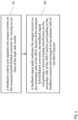
- Fig. 2 shows a flow chart of an exemplary embodiment of a method for controlling the output current of a resonant hybrid flyback converter, comprising a feedback-control unit, a half bridge arrangement comprising a high side switch and a low side switch, and a SELV barrier.
- a feedback signal path indicates the output current on the secondary side of the SELV barrier of the resonant hybrid flyback converter, the feedback signal comprising a current sensing transformer on the secondary side of the SELV barrier and leading to the feedback-control unit arranged on the primary side of the SELV barrier.
Landscapes
- Engineering & Computer Science (AREA)
- Power Engineering (AREA)
- Dc-Dc Converters (AREA)
- Circuit Arrangement For Electric Light Sources In General (AREA)
Abstract
A resonant hybrid flyback converter (10) with output terminals for supplying a LED load (16) is provided. Said resonant hybrid flyback converter (10) comprises a feedback-control unit (11), a half bridge arrangement (12) comprising a high side switch (12a) and a low side switch (12b), and a SELV barrier (13). In this context, the feedback-control unit (11) is arranged for regulating the output current of the resonant hybrid flyback converter (10) by varying an on-time of the high side switch (12a). The resonant hybrid flyback converter (10) further comprises a feedback signal path (14) indicating the output current on the secondary side (13b) of the SELV barrier (13) of the resonant hybrid flyback converter (10), the feedback signal comprising a current sensing transformer on the secondary side (13b) of the SELV barrier (13) and leading to the feedback-control unit (11) arranged on the primary side (13a) of the SELV barrier (13).
Description
- The invention relates to a resonant hybrid flyback converter with output terminals for supplying a LED load, a LED converter comprising such a resonant hybrid flyback converter, and a method for controlling the output current of a resonant hybrid flyback converter.
- Generally, in times of an increasing number of LED lighting applications, there is a growing need of a resonant hybrid flyback converter with output terminals for supplying a LED load, a LED converter comprising such a resonant hybrid flyback converter, and a method for controlling the output current of a resonant hybrid flyback converter in order to supply the corresponding LEDs of such applications with power in a particularly accurate, reliable, and efficient manner.
- Accordingly, there is the object to provide a resonant hybrid flyback converter with output terminals for supplying a LED load, a LED converter comprising such a resonant hybrid flyback converter, and a method for controlling the output current of a resonant hybrid flyback converter, thereby ensuring a particularly high accuracy, reliability, and efficiency in the context of supplying a corresponding LED load with power.
- This object is solved by the features of the first independent claim for a resonant hybrid flyback converter with output terminals for supplying a LED load, the features of the second independent claim for a LED converter comprising such a resonant hybrid flyback converter, and the features of the third independent claim for a method for controlling the output current of a resonant hybrid flyback converter.
- According to a first aspect of the invention, a resonant hybrid flyback converter with output terminals for supplying a LED load is provided. Said resonant converter hybrid flyback comprises a feedback-control unit, a half bridge arrangement comprising a high side switch and a low side switch, and a SELV barrier. In this context, the feedback-control unit is arranged for regulating the output current of the resonant hybrid flyback converter by varying an on-time of the high side switch. The resonant hybrid flyback converter furthermore comprises a feedback signal path indicating the output current on the secondary side of the SELV barrier of the resonant hybrid flyback converter, the feedback signal comprising a current sensing transformer on the secondary side of the SELV barrier and leading to the feedback-control unit arranged on the primary side of the SELV barrier. Advantageously, a particularly high accuracy, reliability, and efficiency can be ensured in the context of supplying a corresponding LED load with power.
- According to an implementation form of the first aspect of the invention, the feedback-control unit comprises an analogue regulator comparing the feedback signal with a nominal value and issuing a control signal as a function of the difference of the feedback signal and the nominal value, and an integrated circuitry, such as an ASIC or microcontroller, being supplied with the control signal at an input pin and issuing a high side switch control switching on and off the high side switch. Advantageously, for instance, efficiency can further be increased.
- According to a further implementation form of the first aspect of the invention, the analogue regulator comprises an operational amplifier supplied with the nominal value and the feedback signal, and one of a PI, P or PID unit supplied with an output signal and issuing the control signal. Advantageously, for example, inefficiencies can further be reduced.
- According to a second aspect of the invention, a LED converter is provided. Said LED converter comprises a resonant hybrid flyback converter according to the first aspect of the invention or any of its implementation forms, respectively, a PFC circuitry supplying the resonant hybrid flyback converter with a DC voltage, and a LED load supplied by said resonant hybrid flyback converter. Advantageously, a particularly high accuracy, reliability, and efficiency can be ensured in the context of supplying the LED load with power.
- According to a third aspect of the invention, a method for controlling the output current of a resonant hybrid flyback converter is provided. Said method comprises a feedback-control unit, a half bridge arrangement comprising a high side switch and a low side switch, and a SELV barrier, wherein the feedback-control unit regulates the output current of the resonant hybrid flyback converter by varying an on-time of the high side switch, and a feedback signal path indicates the output current on the secondary side of the SELV barrier of the resonant hybrid flyback converter, the feedback signal comprising a current sensing transformer on the secondary side of the SELV barrier and leading to the feedback-control unit arranged on the primary side of the SELV barrier. Advantageously, a particularly high accuracy, reliability, and efficiency can be ensured in the context of supplying a corresponding LED load with power.
- According to an implementation form of the third aspect of the invention, an analogue regulator compares the feedback signal with a nominal value and issues a control signal as a function of the difference of the feedback signal and the nominal value, and an integrated circuitry, such as an ASIC or microcontroller, is supplied with the control signal at an input pin and issues a high side switch control switching on and off the high side switch. Advantageously, for instance, efficiency can further be increased.
- Exemplary embodiments of the invention are now further explained with respect to the drawings by way of example only, and not for limitation. In the drawings:
- Fig. 1
- shows an exemplary embodiment of the first aspect of the invention in combination with an exemplary embodiment of a major part of the second aspect of the invention; and
- Fig. 2
- shows a flow chart of an exemplary embodiment of the third aspect of the invention.
- With respect to
Fig. 1 , an exemplary embodiment of a resonanthybrid flyback converter 10 with output terminals for supplying aLED load 16 is depicted. - In accordance with said
Fig. 1 , said resonanthybrid flyback converter 10 comprises a feedback-control unit 11, ahalf bridge arrangement 12 comprising ahigh side switch 12a, especially a high side field-effect transistor, and alow side switch 12b, especially a low side field-effect transistor, and aSELV barrier 13. - In this context, the feedback-
control unit 11 is arranged for regulating the output current of the resonanthybrid flyback converter 10 by varying an on-time of thehigh side switch 12a. - Furthermore, the resonant
hybrid flyback converter 10 comprises afeedback signal path 14 indicating the output current on thesecondary side 13b of theSELV barrier 13 of the resonanthybrid flyback converter 10, the feedback signal comprising a current sensing transformer on thesecondary side 13b of theSELV barrier 13 and leading to the feedback-control unit 11 arranged on theprimary side 13a of theSELV barrier 13. - As it can further be seen from
Fig. 1 , the feedback-control unit 11 exemplarily comprises an analogue regulator 11a comparing the feedback signal with a nominal value and issuing a control signal as a function of the difference of the feedback signal and the nominal value, and anintegrated circuitry 11b, such as an ASIC or microcontroller, being supplied with the control signal at an input pin and issuing a high side switch control switching on and off thehigh side switch 12a. - With respect to the analogue regulator 11a, it is noted that the analogue regulator 11a exemplarily comprises an
operational amplifier 15 supplied with the nominal value and the feedback signal, and one of a PI, P or PID unit supplied with an output signal and issuing the control signal. - In this exemplary case, as it can be seen from
Fig. 1 , a PI unit is used. Accordingly, the analogue regulator 11a may especially be understood as a PI regulator in this exemplary case according toFig. 1 . - For the sake of completeness, it is noted that
Fig. 1 illustrate at least a major part of aLED converter 20 comprising the resonanthybrid flyback converter 10, a PFC circuitry supplying the resonanthybrid flyback converter 10 with a DC voltage, and theLED load 16 supplied by said resonanthybrid flyback converter 10. In this context, said PFC circuitry is not explicitly shown. - With respect to the above-mentioned PFC circuitry, it is noted that said PFC circuitry may especially comprise or be a boost PFC circuitry.
- In addition to all the explanations above, the corresponding functioning of the resonant
hybrid flyback converter 10 or theLED converter 20, respectively, is summarized in the following. - Firstly, it is noted that the feedback-
control unit 11, especially the integratedcircuitry 11b, is used for LED current control with respect to theLED load 16. - Furthermore, the corresponding secondary side current is sensed exemplarily by a current sense transformer. Then, the correspondingly gained information is handed over to the primary side and an analog LED current regulation is done with aid of the feedback-
control unit 11, especially with the aid of the analogue regulator 11a. - Moreover, the output of said regulation is the feedback signal which is fed into the feedback-
control unit 11, especially the integratedcircuitry 11b. - In addition to this, the analog regulation is exemplarily built up by the
operational amplifier 15 and can be executed as P, PI or PID controller, exemplarily PI controller as already mentioned above. - Finally,
Fig. 2 shows a flow chart of an exemplary embodiment of a method for controlling the output current of a resonant hybrid flyback converter, comprising a feedback-control unit, a half bridge arrangement comprising a high side switch and a low side switch, and a SELV barrier. - As it can be seen from said
Fig. 2 , in accordance with afirst step 31, the feedback-control unit regulates the output current of the resonant hybrid flyback converter by varying an on-time of the high side switch. - In addition to this, in accordance with a
second step 32, a feedback signal path indicates the output current on the secondary side of the SELV barrier of the resonant hybrid flyback converter, the feedback signal comprising a current sensing transformer on the secondary side of the SELV barrier and leading to the feedback-control unit arranged on the primary side of the SELV barrier. - It is noted that it might be particularly advantageous if an analogue regulator compares the feedback signal with a nominal value and issues a control signal as a function of the difference of the feedback signal and the nominal value, and an integrated circuitry, such as an ASIC or microcontroller, is supplied with the control signal at an input pin and issues a high side switch control switching on and off the high side switch.
- It is further noted that it might be particularly advantageous if the method uses the resonant
hybrid flyback converter 10 according toFig. 1 . - Accordingly, the resonant hybrid flyback converter or the corresponding elements thereof, respectively, mentioned in the context of the method may especially be understood as the respective elements of
Fig. 1 . - While various embodiments of the present invention have been described above, it should be understood that they have been presented by way of example only, and not limitation. Numerous changes to the disclosed embodiments can be made in accordance with the disclosure herein without departing from the spirit or scope of the invention. Thus, the breadth and scope of the present invention should not be limited by any of the above described embodiments. Rather, the scope of the invention should be defined in accordance with the following claims and their equivalents.
- Although the invention has been illustrated and described with respect to one or more implementations, equivalent alterations and modifications will occur to others skilled in the art upon the reading and understanding of this specification and the annexed drawings. In addition, while a particular feature of the invention may have been disclosed with respect to only one of several implementations, such feature may be combined with one or more other features of the other implementations as may be desired and advantageous for any given or particular application.
Claims (6)
- Resonant hybrid flyback converter (10) with output terminals for supplying a LED load (16),
comprising:a feedback-control unit (11),a half bridge arrangement (12) comprising a high side switch (12a) and a low side switch (12b), anda SELV barrier (13),wherein the feedback-control unit (11) is arranged for regulating the output current of the resonant hybrid flyback converter (10) by varying an on-time of the high side switch (12a),furthermore comprising:
a feedback signal path (14) indicating the output current on the secondary side of the SELV barrier (13) of the resonant hybrid flyback converter (10), the feedback signal comprising a current sensing transformer on the secondary side (13b) of the SELV barrier (13) and leading to the feedback-control unit (11) arranged on the primary side (13a) of the SELV barrier (13). - The resonant hybrid flyback converter (10) of claim 1, wherein the feedback-control unit (11) comprises:an analogue regulator (11a) comparing the feedback signal with a nominal value and issuing a control signal as a function of the difference of the feedback signal and the nominal value, andan integrated circuitry (11b), such as an ASIC or microcontroller, being supplied with the control signal at an input pin and issuing a high side switch control switching on and off the high side switch (12a).
- The resonant hybrid flyback converter (10) of claim 2, wherein the analogue regulator (11a) comprises an operational amplifier (15) supplied with the nominal value and the feedback signal, and one of a PI, P or PID unit supplied with an output signal and issuing the control signal.
- A LED converter (20) comprising:a resonant hybrid flyback converter (10) according to any of the preceding claims,a PFC circuitry supplying the resonant hybrid flyback converter (10) with a DC voltage, anda LED load (16) supplied by said resonant hybrid flyback converter (10).
- A method for controlling the output current of a resonant hybrid flyback converter (10),
comprising:a feedback-control unit (11),a half bridge arrangement (12) comprising a high side switch (12a) and a low side switch (12b), anda SELV barrier (13),wherein the feedback-control unit (11) regulates (31) the output current of the resonant hybrid flyback converter (10) by varying an on-time of the high side switch (12a), and a feedback signal path (14) indicates (32) the output current on the secondary side (13b) of the SELV barrier (13) of the resonant hybrid flyback converter (10), the feedback signal comprising a current sensing transformer on the secondary side (13b) of the SELV barrier (13) and leading to the feedback-control unit (11) arranged on the primary side (13a) of the SELV barrier (13). - The method of claim 5,wherein an analogue regulator (11a) compares the feedback signal with a nominal value and issues a control signal as a function of the difference of the feedback signal and the nominal value, andan integrated circuitry (11b), such as an ASIC or microcontroller, is supplied with the control signal at an input pin and issues a high side switch control switching on and off the high side switch (12a).
Priority Applications (2)
| Application Number | Priority Date | Filing Date | Title |
|---|---|---|---|
| EP23202297.0A EP4539323A1 (en) | 2023-10-09 | 2023-10-09 | Resonant hybrid flyback converter, led converter comprising the latter, and corresponding control method |
| PCT/EP2024/078188 WO2025078322A1 (en) | 2023-10-09 | 2024-10-08 | Resonant hybrid flyback converter, led converter comprising the latter, and corresponding control method |
Applications Claiming Priority (1)
| Application Number | Priority Date | Filing Date | Title |
|---|---|---|---|
| EP23202297.0A EP4539323A1 (en) | 2023-10-09 | 2023-10-09 | Resonant hybrid flyback converter, led converter comprising the latter, and corresponding control method |
Publications (1)
| Publication Number | Publication Date |
|---|---|
| EP4539323A1 true EP4539323A1 (en) | 2025-04-16 |
Family
ID=88297001
Family Applications (1)
| Application Number | Title | Priority Date | Filing Date |
|---|---|---|---|
| EP23202297.0A Pending EP4539323A1 (en) | 2023-10-09 | 2023-10-09 | Resonant hybrid flyback converter, led converter comprising the latter, and corresponding control method |
Country Status (2)
| Country | Link |
|---|---|
| EP (1) | EP4539323A1 (en) |
| WO (1) | WO2025078322A1 (en) |
Citations (9)
| Publication number | Priority date | Publication date | Assignee | Title |
|---|---|---|---|---|
| US20160302268A1 (en) * | 2013-12-03 | 2016-10-13 | Tridonic Gmbh & Co Kg | Driver Circuit for Illuminants, Particularly LEDs |
| US20170238379A1 (en) * | 2014-10-17 | 2017-08-17 | Tridonic Gmbh & Co Kg | Operating Circuit for Energizing a Lamp, LED Converter, and Method for Operating an Operating Circuit |
| US20180027621A1 (en) * | 2015-04-17 | 2018-01-25 | Tridonic Gmbh & Co Kg | Converter for light sources |
| EP3269207B1 (en) * | 2015-03-11 | 2020-05-06 | Tridonic GmbH & Co. KG | Isolated interface with current transformer |
| EP3961892A1 (en) * | 2020-09-01 | 2022-03-02 | Tridonic GmbH & Co. KG | Led converter |
| US20220264723A1 (en) * | 2018-07-30 | 2022-08-18 | Lutron Technology Company Llc | Load control device for a light-emitting diode light source |
| US20220393601A1 (en) * | 2019-11-18 | 2022-12-08 | Tridonic Gmbh & Co Kg | Isolated primary side switched converter |
| US20230171863A1 (en) * | 2020-04-24 | 2023-06-01 | Redisem Ltd. | Power Converter and Method of Converting Power |
| EP4220925A1 (en) * | 2022-01-26 | 2023-08-02 | Tridonic GmbH & Co. KG | A switched converter |
-
2023
- 2023-10-09 EP EP23202297.0A patent/EP4539323A1/en active Pending
-
2024
- 2024-10-08 WO PCT/EP2024/078188 patent/WO2025078322A1/en active Pending
Patent Citations (9)
| Publication number | Priority date | Publication date | Assignee | Title |
|---|---|---|---|---|
| US20160302268A1 (en) * | 2013-12-03 | 2016-10-13 | Tridonic Gmbh & Co Kg | Driver Circuit for Illuminants, Particularly LEDs |
| US20170238379A1 (en) * | 2014-10-17 | 2017-08-17 | Tridonic Gmbh & Co Kg | Operating Circuit for Energizing a Lamp, LED Converter, and Method for Operating an Operating Circuit |
| EP3269207B1 (en) * | 2015-03-11 | 2020-05-06 | Tridonic GmbH & Co. KG | Isolated interface with current transformer |
| US20180027621A1 (en) * | 2015-04-17 | 2018-01-25 | Tridonic Gmbh & Co Kg | Converter for light sources |
| US20220264723A1 (en) * | 2018-07-30 | 2022-08-18 | Lutron Technology Company Llc | Load control device for a light-emitting diode light source |
| US20220393601A1 (en) * | 2019-11-18 | 2022-12-08 | Tridonic Gmbh & Co Kg | Isolated primary side switched converter |
| US20230171863A1 (en) * | 2020-04-24 | 2023-06-01 | Redisem Ltd. | Power Converter and Method of Converting Power |
| EP3961892A1 (en) * | 2020-09-01 | 2022-03-02 | Tridonic GmbH & Co. KG | Led converter |
| EP4220925A1 (en) * | 2022-01-26 | 2023-08-02 | Tridonic GmbH & Co. KG | A switched converter |
Non-Patent Citations (2)
| Title |
|---|
| CHOI W Y ET AL: "Efficient LED back-light power supply for liquid-crystal-display", 20070301, vol. 1, no. 2, 1 March 2007 (2007-03-01), pages 133 - 142, XP006028320 * |
| FRANCESCO SICHIROLLO ET AL: "Use of current controlled mutual inductor to limit recycling current in the AHB-Flyback converter", IECON 2012 - 38TH ANNUAL CONFERENCE ON IEEE INDUSTRIAL ELECTRONICS SOCIETY, IEEE, 25 October 2012 (2012-10-25), pages 4611 - 4616, XP032281786, ISBN: 978-1-4673-2419-9, DOI: 10.1109/IECON.2012.6389504 * |
Also Published As
| Publication number | Publication date |
|---|---|
| WO2025078322A1 (en) | 2025-04-17 |
Similar Documents
| Publication | Publication Date | Title |
|---|---|---|
| JP2010109168A (en) | Led driving device, led driving method, and lighting device | |
| US8519642B2 (en) | LED light emitting device | |
| CN101707874B (en) | Power control system for current regulated light sources | |
| US9837913B1 (en) | Control method to avoid capacitive mode switching for resonant converters | |
| US8044609B2 (en) | Circuits and methods for controlling LCD backlights | |
| JP4776596B2 (en) | Lighting control device for vehicle lamp | |
| US8610375B2 (en) | Adaptive bleeder circuit | |
| US10512137B2 (en) | LED drive circuit | |
| US20150091472A1 (en) | Lighting device | |
| US20060231745A1 (en) | Method and circuit arrangement for driving light-emitting diodes | |
| US9398672B2 (en) | Lighting device and illumination apparatus | |
| EP2563095A2 (en) | Lighting device, headlamp lighting device, and headlamp unit and vehicle having same | |
| Lohaus et al. | A dimmable LED driver with resistive DAC feedback control for adaptive voltage regulation | |
| US9210748B2 (en) | Systems and methods of driving multiple outputs | |
| US6977830B2 (en) | Power supply apparatus | |
| US7851940B2 (en) | Methods and apparatus for DC-DC converter having independent outputs | |
| US8957592B2 (en) | Electrical power conversion device and lighting device | |
| JP6320455B2 (en) | LED lighting device | |
| JP5289084B2 (en) | Power supply circuit and lighting device | |
| WO2025078322A1 (en) | Resonant hybrid flyback converter, led converter comprising the latter, and corresponding control method | |
| JP2018019025A (en) | Voltage conversion circuit, LED drive circuit, and voltage conversion circuit control method | |
| US11729883B1 (en) | LED driver with auxiliary output and low standby power | |
| TW200816127A (en) | Lighting apparatus and driving circuit thereof | |
| JP2016170894A (en) | Lighting device and illuminating fixture | |
| JP7484522B2 (en) | Lighting fixture, connection unit and lighting device |
Legal Events
| Date | Code | Title | Description |
|---|---|---|---|
| PUAI | Public reference made under article 153(3) epc to a published international application that has entered the european phase |
Free format text: ORIGINAL CODE: 0009012 |
|
| STAA | Information on the status of an ep patent application or granted ep patent |
Free format text: STATUS: THE APPLICATION HAS BEEN PUBLISHED |
|
| AK | Designated contracting states |
Kind code of ref document: A1 Designated state(s): AL AT BE BG CH CY CZ DE DK EE ES FI FR GB GR HR HU IE IS IT LI LT LU LV MC ME MK MT NL NO PL PT RO RS SE SI SK SM TR |
|
| STAA | Information on the status of an ep patent application or granted ep patent |
Free format text: STATUS: REQUEST FOR EXAMINATION WAS MADE |
|
| 17P | Request for examination filed |
Effective date: 20250903 |