EP4539322A1 - Burst mode control of resonant power converters - Google Patents
Burst mode control of resonant power converters Download PDFInfo
- Publication number
- EP4539322A1 EP4539322A1 EP23202296.2A EP23202296A EP4539322A1 EP 4539322 A1 EP4539322 A1 EP 4539322A1 EP 23202296 A EP23202296 A EP 23202296A EP 4539322 A1 EP4539322 A1 EP 4539322A1
- Authority
- EP
- European Patent Office
- Prior art keywords
- pwm
- resonant power
- time periods
- power converter
- time period
- Prior art date
- Legal status (The legal status is an assumption and is not a legal conclusion. Google has not performed a legal analysis and makes no representation as to the accuracy of the status listed.)
- Withdrawn
Links
Images



Classifications
-
- H—ELECTRICITY
- H02—GENERATION; CONVERSION OR DISTRIBUTION OF ELECTRIC POWER
- H02M—APPARATUS FOR CONVERSION BETWEEN AC AND AC, BETWEEN AC AND DC, OR BETWEEN DC AND DC, AND FOR USE WITH MAINS OR SIMILAR POWER SUPPLY SYSTEMS; CONVERSION OF DC OR AC INPUT POWER INTO SURGE OUTPUT POWER; CONTROL OR REGULATION THEREOF
- H02M1/00—Details of apparatus for conversion
- H02M1/0003—Details of control, feedback or regulation circuits
- H02M1/0032—Control circuits allowing low power mode operation, e.g. in standby mode
- H02M1/0035—Control circuits allowing low power mode operation, e.g. in standby mode using burst mode control
-
- H—ELECTRICITY
- H02—GENERATION; CONVERSION OR DISTRIBUTION OF ELECTRIC POWER
- H02M—APPARATUS FOR CONVERSION BETWEEN AC AND AC, BETWEEN AC AND DC, OR BETWEEN DC AND DC, AND FOR USE WITH MAINS OR SIMILAR POWER SUPPLY SYSTEMS; CONVERSION OF DC OR AC INPUT POWER INTO SURGE OUTPUT POWER; CONTROL OR REGULATION THEREOF
- H02M1/00—Details of apparatus for conversion
- H02M1/0048—Circuits or arrangements for reducing losses
- H02M1/0054—Transistor switching losses
- H02M1/0058—Transistor switching losses by employing soft switching techniques, i.e. commutation of transistors when applied voltage is zero or when current flow is zero
-
- H—ELECTRICITY
- H02—GENERATION; CONVERSION OR DISTRIBUTION OF ELECTRIC POWER
- H02M—APPARATUS FOR CONVERSION BETWEEN AC AND AC, BETWEEN AC AND DC, OR BETWEEN DC AND DC, AND FOR USE WITH MAINS OR SIMILAR POWER SUPPLY SYSTEMS; CONVERSION OF DC OR AC INPUT POWER INTO SURGE OUTPUT POWER; CONTROL OR REGULATION THEREOF
- H02M3/00—Conversion of DC power input into DC power output
- H02M3/01—Resonant DC/DC converters
-
- H—ELECTRICITY
- H02—GENERATION; CONVERSION OR DISTRIBUTION OF ELECTRIC POWER
- H02M—APPARATUS FOR CONVERSION BETWEEN AC AND AC, BETWEEN AC AND DC, OR BETWEEN DC AND DC, AND FOR USE WITH MAINS OR SIMILAR POWER SUPPLY SYSTEMS; CONVERSION OF DC OR AC INPUT POWER INTO SURGE OUTPUT POWER; CONTROL OR REGULATION THEREOF
- H02M3/00—Conversion of DC power input into DC power output
- H02M3/22—Conversion of DC power input into DC power output with intermediate conversion into AC
- H02M3/24—Conversion of DC power input into DC power output with intermediate conversion into AC by static converters
- H02M3/28—Conversion of DC power input into DC power output with intermediate conversion into AC by static converters using discharge tubes with control electrode or semiconductor devices with control electrode to produce the intermediate AC
- H02M3/325—Conversion of DC power input into DC power output with intermediate conversion into AC by static converters using discharge tubes with control electrode or semiconductor devices with control electrode to produce the intermediate AC using devices of a triode or a transistor type requiring continuous application of a control signal
- H02M3/335—Conversion of DC power input into DC power output with intermediate conversion into AC by static converters using discharge tubes with control electrode or semiconductor devices with control electrode to produce the intermediate AC using devices of a triode or a transistor type requiring continuous application of a control signal using semiconductor devices only
- H02M3/33569—Conversion of DC power input into DC power output with intermediate conversion into AC by static converters using discharge tubes with control electrode or semiconductor devices with control electrode to produce the intermediate AC using devices of a triode or a transistor type requiring continuous application of a control signal using semiconductor devices only having several active switching elements
- H02M3/33571—Half-bridge at primary side of an isolation transformer
-
- H—ELECTRICITY
- H05—ELECTRIC TECHNIQUES NOT OTHERWISE PROVIDED FOR
- H05B—ELECTRIC HEATING; ELECTRIC LIGHT SOURCES NOT OTHERWISE PROVIDED FOR; CIRCUIT ARRANGEMENTS FOR ELECTRIC LIGHT SOURCES, IN GENERAL
- H05B45/00—Circuit arrangements for operating light-emitting diodes [LED]
- H05B45/30—Driver circuits
- H05B45/32—Pulse-control circuits
- H05B45/327—Burst dimming
-
- H—ELECTRICITY
- H05—ELECTRIC TECHNIQUES NOT OTHERWISE PROVIDED FOR
- H05B—ELECTRIC HEATING; ELECTRIC LIGHT SOURCES NOT OTHERWISE PROVIDED FOR; CIRCUIT ARRANGEMENTS FOR ELECTRIC LIGHT SOURCES, IN GENERAL
- H05B45/00—Circuit arrangements for operating light-emitting diodes [LED]
- H05B45/30—Driver circuits
- H05B45/37—Converter circuits
- H05B45/3725—Switched mode power supply [SMPS]
- H05B45/39—Circuits containing inverter bridges
Definitions
- the present disclosure relates generally to the field of lighting technology, and more particularly to a resonant power converter for a light source, and to a luminaire comprising the same.
- a low-frequency pulse width modulation may be used to implement a burst mode control of a constant load current in accordance with a given dimming level (see FIG. 3 ).
- This non-monotonicity affects an accurate control of the dimming level as well as a compensation of disturbances by a closed-loop control of the constant load current.
- the resonant power converter may further comprise a memory, being configured to provide the successive values of the respective LF-PWM on-time periods T LF , HS ON , T LF , LS ON .
- a control variable such as an on-time period of a control signal 14, 15 of a switch 11, 12
- P proportional
- I integral
- D derivative
- the LF-PWM and HF-PWM may be synchronized.
- the LF-PWM on-time period T LF ON can only change by half of the HF-PWM cycle period T HF or more, and that higher resolutions, i.e., smaller steps, will lead to non-monocity.
- the LF-PWM on-time period T LF ON has been changed by less than half of the HF-PWM cycle period T HF , such that the HF-PWM on-time period ⁇ ⁇ T HF ON of the last HF-PWM cycle is truncated by the LF-PWM on-time period T LF ON .
- FIG. 4 illustrates a non-monotonic load current provided by the known burst mode control versus the given on-time period T LF ON .
- a resonant power converter In order for a resonant power converter to have Zero Voltage Switching (ZVS) turning on, it is usually used in inductive mode, so that the resonant current lags with respect to the voltage across the tank and load. This lag causes a negative instantaneous input power. In other words, during each half HF cycle, there exists an interval in which the direction of the instantaneous power is backward, i.e. from the resonant circuit to the source.
- ZVS Zero Voltage Switching
- FIG. 5 illustrates a fixed deadtime based burst mode control in accordance with the present disclosure.
- the control circuit 13 is configured to modulate the control signals 14, 15 of the switches 11, 12 concurrently in accordance with LF-PWM having a cycle period T LF and respective on-time periods T LF , HS ON , T LF , LS OB .
- the control circuit 13 is further configured to modulate the control signals 14, 15 of the switches 11, 12 alternatingly in accordance with HF-PWM having a cycle period T HF , a full on-time period T HF ON and a truncated on-time period ⁇ ⁇ T HF ON being truncated in accordance with the LF-PWM.
- the LF-PWM and HF-PWM may be synchronized.
- the full HF-PWM on-time periods T HF ON as well as the truncated HF-PWM on-time periods ⁇ ⁇ T HF ON of the modulated control signals 14, 15 may mutually be spaced by half of the HF-PWM cycle period T HF minus the full HF-PWM on-time period T HF ON (" fixed deadtime ").
- the LF-PWM on-time periods T LF , HS ON , T LF , LS ON of the modulated control signals 14, 15 may thus differ by the truncated HF-PWM on-time period ⁇ ⁇ T HF ON plus half of the HF-PWM cycle period T HF minus the full HF-PWM on-time period T HF ON .
- FIG. 6 illustrates a fixed frequency based burst mode control in accordance with the present disclosure.
- control circuit 13 is configured to modulate the control signals 14, 15 of the switches 11, 12 concurrently in accordance with LF-PWM having the cycle period T LF and the respective on-time periods T LF , HS ON , T LF , LS ON .
- control circuit 13 is configured to modulate the control signals 14, 15 of the switches 11, 12 alternatingly in accordance with HF-PWM having a cycle period T HF , the full on-time period T HF ON and the truncated on-time period ⁇ ⁇ T HF ON being truncated in accordance with the LF-PWM.
- the LF-PWM and HF-PWM may be synchronized.
- the LF-PWM on-time periods T LF , HS ON , T LF , LS ON of the modulated control signals 14, 15 may thus differ by half of the HF-PWM cycle period T HF .
- FIG. 7 illustrates a chirped frequency based burst mode control in accordance with the present disclosure.
- control circuit 13 is configured to modulate the control signals 14, 15 of the switches 11, 12 alternatingly in accordance with HF-PWM having a cycle period T HF , the full on-time period T HF ON and the truncated on-time period ⁇ ⁇ T HF ON being truncated in accordance with the LF-PWM.
- the truncated HF-PWM on-time periods ⁇ ⁇ T HF ON of the modulated control signals 14, 15 may mutually be shifted by half of the HF-PWM cycle period T HF minus a stepwise adjustable time period n ⁇ ⁇ t ( "chirped frequency" ) .
- the LF-PWM on-time periods T LF , HS ON , T LF , LS ON of the modulated control signals 14, 15 may thus differ by the truncated HF-PWM on-time period ⁇ ⁇ T HF ON plus half of the HF-PWM cycle period T HF minus the stepwise adjustable time period n ⁇ ⁇ t.
- FIG. 8 illustrates a monotonic load current provided by the chirped frequency based burst mode control versus the given on-time period T LF ON .
- integration over the last HF cycle yields positive values which increase the transmitted average (output) power due to HF-PWM such that the depicted black monotonic curve of the load power is obtained.
- the grey non-monotonic curve of FIG. 4 as a reference representing ordinary LF-PWM, wherein the integral over ⁇ may yield a negative value, depending on ⁇ (i.e., the HF-PWM on-time period ⁇ ⁇ T HF ON of the last HF-PWM cycle being truncated by the LF-PWM on-time period T LF ON ).
- FIG. 9 illustrates a fixed frequency based burst mode control featuring pulse frequency modulation, in accordance with the present disclosure.
- the control circuit 13 may further be configured to modulate the control signals 14, 15 of the switches 11, 12 concurrently in accordance with low-frequency pulse frequency modulations (LF-PFM) having a stepwise adjustable off-time period T LF OFF between successive values of the respective LF-PWM on-time periods T LF , HS ON , T LF , LS ON .
- LF-PFM low-frequency pulse frequency modulations
- off-time period T LF OFF may also undergo stepwise adjustment in terms of a decrease as well.
- the memory 16 mentioned in connection with FIGs. 1, 2 may be configured to provide the successive values of the respective LF-PWM on-time periods T LF , HS ON , T LF , LS ON .
- a computer program may be stored/distributed on a suitable medium, such as an optical storage medium or a solid-state medium supplied together with or as part of other hardware, but may also be distributed in other forms, such as via the Internet or other wired or wireless telecommunication systems.
- a suitable medium such as an optical storage medium or a solid-state medium supplied together with or as part of other hardware, but may also be distributed in other forms, such as via the Internet or other wired or wireless telecommunication systems.
Landscapes
- Engineering & Computer Science (AREA)
- Power Engineering (AREA)
- Dc-Dc Converters (AREA)
Abstract
Disclosed is a resonant power converter (1) for a light source (2). The converter (1) comprises a highside switch (11) and a low-side switch (12) connected in series between input electric potentials of the converter (1); and a control circuit (13), being configured to modulate control signals (14, 15) of the switches (11, 12) concurrently in accordance with low-frequency pulse-width modulations, LF-PWM, having a cycle period T LF and respective on-time periods 
, and alternatingly in accordance with high-frequency pulse width modulations, HF-PWM, having a cycle period T HF , a full on-time period 
and a truncated on-time period 
being truncated in accordance with the LF-PWM. This provides an accurate control of a dimming level of the light source (2) as well as a precise closed-loop control of the constant load current (or voltage).
Description
- The present disclosure relates generally to the field of lighting technology, and more particularly to a resonant power converter for a light source, and to a luminaire comprising the same.
- In high-frequency pulse width modulated (HF-PWM) resonant power converters (see
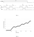
FIGs. 1, 2 ), a low-frequency pulse width modulation (LF-PWM) may be used to implement a burst mode control of a constant load current in accordance with a given dimming level (seeFIG. 3 ). - By increasing an on-time period

FIG. 3 ). This non-monotonic behavior is due to the traditional LF-PWM burst control. Mathematically, it may be demonstrated that the on-time period
- This non-monotonicity affects an accurate control of the dimming level as well as a compensation of disturbances by a closed-loop control of the constant load current.
- It is an object to overcome these and other drawbacks of the prior art.
- The foregoing and other objects are achieved by the features of the independent claims. Further implementation forms are apparent from the dependent claims, the description and the figures.
- According to a first aspect, a resonant power converter for a light source is provided. The converter comprises a high-side switch and a low-side switch connected in series between input electric potentials of the converter; and a control circuit, being configured to modulate control signals of the switches concurrently in accordance with low-frequency pulse-width modulations, LF-PWM, having a cycle period T LF and respective on-time periods



- The full HF-PWM on-time periods

- The truncated HF-PWM on-time periods


- The LF-PWM on-time periods


- The truncated HF-PWM on-time periods

- The LF-PWM on-time periods

- The truncated HF-PWM on-time periods

- The LF-PWM on-time periods


- The control circuit may further be configured to modulate the control signals of the switches concurrently in accordance with low-frequency pulse frequency modulations, LF-PFM, having a stepwise adjustable off-time period


- The resonant power converter may further comprise a memory, being configured to provide the successive values of the respective LF-PWM on-time periods

- The memory may further be configured to provide a step size of the LF-PFM off-time periods


- The LF-PWM and HF-PWM may be synchronized.
- According to a second aspect, a luminaire is provided, comprising a resonant power converter of the first aspect and a light source.
- The light source may comprise at least one light-emitting diode, LED.
- The present disclosure provides a burst mode controlled resonant converter providing monotonic output power/current and, as a side aspect, high dimming resolution at low output power/currents.
- This results in an accurate control of the dimming level as well as a precise closed-loop control of the constant load current (or voltage).
- The above-described aspects and implementations will now be explained with reference to the accompanying drawings, in which the same or similar reference numerals designate the same or similar elements.
- The drawings are to be regarded as being schematic representations, and elements illustrated in the drawings are not necessarily shown to scale. Rather, the various elements are represented such that their function and general purpose become apparent to those skilled in the art.
- FIGs. 1,2
- illustrate exemplary resonant power converters;
- FIG. 3
- illustrates a known burst mode control in accordance with a given on-time period

- FIG. 4
- illustrates a non-monotonic load current provided by the known burst mode control versus the given on-time period

- FIG. 5
- illustrates a fixed deadtime based burst mode control in accordance with the present disclosure;
- FIG. 6
- illustrates a fixed frequency based burst mode control in accordance with the present disclosure;
- FIG. 7
- illustrates a chirped frequency based burst mode control in accordance with the present disclosure;
- FIG. 8
- illustrates a monotonic load current provided by the chirped frequency based burst mode control versus the given on-time period

- FIG. 9
- illustrates a fixed frequency based burst mode control featuring pulse frequency modulation, in accordance with the present disclosure.
- In the following description, reference is made to the accompanying drawings, which form part of the disclosure, and which show, by way of illustration, specific aspects of embodiments of the invention or specific aspects in which embodiments of the present invention may be used. It is understood that embodiments of the invention may be used in other aspects and comprise structural or logical changes not depicted in the figures. The following detailed description, therefore, is not to be taken in a limiting sense, and the scope of the present invention is defined by the appended claims.
- For instance, it is understood that a disclosure in connection with a described method may also hold true for a corresponding apparatus or system configured to perform the method and vice versa. For example, if one or a plurality of specific method steps are described, a corresponding device may include one or a plurality of units, e.g. functional units, to perform the described one or plurality of method steps (e.g. one unit performing the one or plurality of steps, or a plurality of units each performing one or more of the plurality of steps), even if such one or more units are not explicitly described or illustrated in the figures. On the other hand, for example, if a specific apparatus is described based on one or a plurality of units, e.g. functional units, a corresponding method may include one step to perform the functionality of the one or plurality of units (e.g. one step performing the functionality of the one or plurality of units, or a plurality of steps each performing the functionality of one or more of the plurality of units), even if such one or plurality of steps are not explicitly described or illustrated in the figures. Further, it is understood that the features of the various exemplary embodiments and/or aspects described herein may be combined with each other, unless specifically noted otherwise.
-
FIGs. 1,2 illustrate exemplaryresonant power converters 1. - More specifically,
FIGs. 1, 2 show luminaires respectively comprising aresonant power converter 1 of the first aspect and a light source 2 (i.e., load). - The
light source 2 may comprise at least one light-emitting diode (LED). - Both
converters 1 respectively comprise a high-side switch 11 and a low-side switch 12 connected in series between input electric potentials of the converter 1 (i.e., a switching half-bridge/HB), and acontrol circuit 13, such as an application-specific integrated circuit (ASIC) or a microcontroller (µC). Note that theswitches - The
converter 1 ofFIG. 1 comprises an LCC topology (suitable as constant current source), whereas theconverter 1 ofFIG. 2 includes an LLC topology (suitable as constant voltage source). - The
converters 1 may further comprise amemory 16 being explained in more detail below, such as an electrically erasable programmable read-only memory (EPROM). - In accordance with a closed-loop control of a process variable such as a load current (or voltage), the same may be sensed, digitized, and subtracted from a desired setpoint to obtain a control error. In dependence of said control error, a control variable (such as an on-time period of a
control signal switch 11, 12) for theconverter 1 may be provided, based on proportional (P), integral (I) and/or derivative (D) terms. Typically a PI controller/compensator implementing P and I terms is deployed. -
FIG. 3 illustrates a known burst mode control in accordance with a given on-time period
- The topmost waveform of
FIG. 3 provides a low-frequency pulse-width modulation (LF-PWM) having a cycle period T LF and an on-time period
light source 2, and the waveforms underneath provide the high-frequency pulse width modulations (HF-PWM) having a cycle period THF, a full on-time period

- In particular, the LF-PWM and HF-PWM may be synchronized.
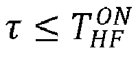
- As mentioned previously, it may be demonstrated that to prevent non-monotonicity, the LF-PWM on-time period

FIG. 3 , the LF-PWM on-time period


-
FIG. 4 illustrates a non-monotonic load current provided by the known burst mode control versus the given on-time period
- In order for a resonant power converter to have Zero Voltage Switching (ZVS) turning on, it is usually used in inductive mode, so that the resonant current lags with respect to the voltage across the tank and load. This lag causes a negative instantaneous input power. In other words, during each half HF cycle, there exists an interval in which the direction of the instantaneous power is backward, i.e. from the resonant circuit to the source.
- It is mathematically proven that using a LF-PWM to control the average output power POut of the
converter 1 corresponds to a definite integral from 0 to

- As

-
FIG. 5 illustrates a fixed deadtime based burst mode control in accordance with the present disclosure. - The
control circuit 13 is configured to modulate the control signals 14, 15 of theswitches 
- The
control circuit 13 is further configured to modulate the control signals 14, 15 of theswitches 

- In particular, the LF-PWM and HF-PWM may be synchronized.
- The full (n = 1..N) HF-PWM on-time periods

- From a different perspective, the full HF-PWM on-time periods


- The LF-PWM on-time periods


-
FIG. 6 illustrates a fixed frequency based burst mode control in accordance with the present disclosure. - As in the implementation of
FIG. 5 , thecontrol circuit 13 is configured to modulate the control signals 14, 15 of theswitches 
- It further applies that the
control circuit 13 is configured to modulate the control signals 14, 15 of theswitches 

- In particular, the LF-PWM and HF-PWM may be synchronized.
- Still, the full (n = 1.. N) HF-PWM on-time periods


- The LF-PWM on-time periods

-
FIG. 7 illustrates a chirped frequency based burst mode control in accordance with the present disclosure. - As in the implementation of
FIG. 6 , thecontrol circuit 13 is configured to modulate the control signals 14, 15 of theswitches 
- It also applies that the
control circuit 13 is configured to modulate the control signals 14, 15 of theswitches 

- Again, the full (n = 1..N) HF-PWM on-time periods

FIG. 6 , the truncated HF-PWM on-time periods
- Note that this implementation may be seen as a middle ground between the "fixed deadtime " (
FIG. 5 ) and "fixed frequency" (FIG. 6 ) implementations, because the stepwise adjustable time period n · Δt may - at least in theory - amount to the full HF-PWM on-time period

- The LF-PWM on-time periods


-
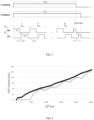
FIG. 8 illustrates a monotonic load current provided by the chirped frequency based burst mode control versus the given on-time period
- In the implementations of
FIGs. 5 - 7 , integration over the last HF cycle yields positive values which increase the transmitted average (output) power due to HF-PWM such that the depicted black monotonic curve of the load power is obtained. Note the grey non-monotonic curve ofFIG. 4 as a reference representing ordinary LF-PWM, wherein the integral over τ may yield a negative value, depending on τ (i.e., the HF-PWM on-time period

-
FIG. 9 illustrates a fixed frequency based burst mode control featuring pulse frequency modulation, in accordance with the present disclosure. - The
control circuit 13 may further be configured to modulate the control signals 14, 15 of theswitches 

- In accordance with
FIG. 9 , consider a ramp-up of the dimming level (i.e., duty cycle DLF) of thelight source 2. Starting on the lowest LF-PFM curve corresponding to


- Again, the off-time period


- Note that the off-time period

- This provides high dimming resolution especially at low load currents.
- The
memory 16 mentioned in connection withFIGs. 1, 2 may be configured to provide the successive values of the respective LF-PWM on-time periods
- The
memory 16 may further be configured to provide a step size (along the respective curve) of the LF-PFM off-time periods

- The present disclosure has been described in conjunction with various embodiments as examples as well as implementations. However, other variations can be understood and effected by those persons skilled in the art and practicing the claimed matter, from the studies of the drawings, this disclosure and the independent claims. In the claims as well as in the description the word "comprising" does not exclude other elements or steps and the indefinite article "a" or "an" does not exclude a plurality. A single element or other unit may fulfill the functions of several entities or items recited in the claims. The mere fact that certain measures are recited in the mutual different dependent claims does not indicate that a combination of these measures cannot be used in an advantageous implementation. A computer program may be stored/distributed on a suitable medium, such as an optical storage medium or a solid-state medium supplied together with or as part of other hardware, but may also be distributed in other forms, such as via the Internet or other wired or wireless telecommunication systems.
Claims (14)
- A resonant power converter (1) for a light source (2), comprisinga high-side switch (11) and a low-side switch (12) connected in series between input electric potentials of the converter (1); anda control circuit (13), being configured to modulate control signals (14, 15) of the switches (11, 12)- concurrently in accordance with low-frequency pulse-width modulations, LF-PWM, having a cycle period TLF and respective on-time periods
 - alternatingly in accordance with high-frequency pulse width modulations, HF-PWM, having a cycle period THF, a full on-time period

- The resonant power converter (1) of claim 1,
the full HF-PWM on-time periods
- The resonant power converter (1) of claim 2,
the truncated HF-PWM on-time periods

- The resonant power converter (1) of claim 3,
the LF-PWM on-time periods


- The resonant power converter (1) of claim 2,
the truncated HF-PWM on-time periods
- The resonant power converter (1) of claim 5,
the LF-PWM on-time periods
- The resonant power converter (1) of claim 2,
the truncated HF-PWM on-time periods
- The resonant power converter (1) of claim 7,
the LF-PWM on-time periods

- The resonant power converter (1) of any one of the claims 1 - 8,
the control circuit (13) further being configured to modulate the control signals (14, 15) of the switches (11, 12)- concurrently in accordance with low-frequency pulse frequency modulations, LF-PFM, having a stepwise adjustable off-time period

- The resonant power converter (1) of claim 9, further comprising
a memory (16), being configured to- provide the successive values of the respective LF-PWM on-time periods
- The resonant power converter (1) of claim 10,
the memory (16) further being configured to- provide a step size of the LF-PFM off-time periods

- The resonant power converter (1) of any one of the claims 1 - 11,
the LF-PWM and HF-PWM being synchronized. - A luminaire, comprisinga resonant power converter (1) of any one of the claims 1 - 12; anda light source (2).
- The luminaire of claim 13,
the light source (2) comprising at least one light-emitting diode, LED.
Priority Applications (3)
| Application Number | Priority Date | Filing Date | Title |
|---|---|---|---|
| EP23202296.2A EP4539322A1 (en) | 2023-10-09 | 2023-10-09 | Burst mode control of resonant power converters |
| PCT/EP2024/077558 WO2025078206A1 (en) | 2023-10-09 | 2024-10-01 | Burst mode control of resonant power converters |
| EP24782576.3A EP4767430A1 (en) | 2023-10-09 | 2024-10-01 | Burst mode control of resonant power converters |
Applications Claiming Priority (1)
| Application Number | Priority Date | Filing Date | Title |
|---|---|---|---|
| EP23202296.2A EP4539322A1 (en) | 2023-10-09 | 2023-10-09 | Burst mode control of resonant power converters |
Publications (1)
| Publication Number | Publication Date |
|---|---|
| EP4539322A1 true EP4539322A1 (en) | 2025-04-16 |
Family
ID=88296965
Family Applications (2)
| Application Number | Title | Priority Date | Filing Date |
|---|---|---|---|
| EP23202296.2A Withdrawn EP4539322A1 (en) | 2023-10-09 | 2023-10-09 | Burst mode control of resonant power converters |
| EP24782576.3A Pending EP4767430A1 (en) | 2023-10-09 | 2024-10-01 | Burst mode control of resonant power converters |
Family Applications After (1)
| Application Number | Title | Priority Date | Filing Date |
|---|---|---|---|
| EP24782576.3A Pending EP4767430A1 (en) | 2023-10-09 | 2024-10-01 | Burst mode control of resonant power converters |
Country Status (2)
| Country | Link |
|---|---|
| EP (2) | EP4539322A1 (en) |
| WO (1) | WO2025078206A1 (en) |
Citations (3)
| Publication number | Priority date | Publication date | Assignee | Title |
|---|---|---|---|---|
| US20100020570A1 (en) * | 2008-07-25 | 2010-01-28 | Melanson John L | Resonant switching power converter with burst mode transition shaping |
| US20140312789A1 (en) * | 2013-04-23 | 2014-10-23 | Virginia Tech Intellectual Properties, Inc. | Optimal Trajectory Control for LLC Resonant Converter for LED PWM Dimming |
| US20150084544A1 (en) * | 2012-03-21 | 2015-03-26 | Tridonic Gmbh & Co Kg | Operating circuit for leds, having dimming signal comprising high-frequency modulated pulse packet signal with harmonized frequencies |
-
2023
- 2023-10-09 EP EP23202296.2A patent/EP4539322A1/en not_active Withdrawn
-
2024
- 2024-10-01 EP EP24782576.3A patent/EP4767430A1/en active Pending
- 2024-10-01 WO PCT/EP2024/077558 patent/WO2025078206A1/en not_active Ceased
Patent Citations (3)
| Publication number | Priority date | Publication date | Assignee | Title |
|---|---|---|---|---|
| US20100020570A1 (en) * | 2008-07-25 | 2010-01-28 | Melanson John L | Resonant switching power converter with burst mode transition shaping |
| US20150084544A1 (en) * | 2012-03-21 | 2015-03-26 | Tridonic Gmbh & Co Kg | Operating circuit for leds, having dimming signal comprising high-frequency modulated pulse packet signal with harmonized frequencies |
| US20140312789A1 (en) * | 2013-04-23 | 2014-10-23 | Virginia Tech Intellectual Properties, Inc. | Optimal Trajectory Control for LLC Resonant Converter for LED PWM Dimming |
Non-Patent Citations (1)
| Title |
|---|
| FENG WEIYI ET AL: "Optimal Trajectory Control of LLC Resonant Converters for LED PWM Dimming", IEEE TRANSACTIONS ON POWER ELECTRONICS, INSTITUTE OF ELECTRICAL AND ELECTRONICS ENGINEERS, USA, vol. 29, no. 2, 1 February 2014 (2014-02-01), pages 979 - 987, XP011524645, ISSN: 0885-8993, [retrieved on 20130820], DOI: 10.1109/TPEL.2013.2257864 * |
Also Published As
| Publication number | Publication date |
|---|---|
| WO2025078206A1 (en) | 2025-04-17 |
| EP4767430A1 (en) | 2026-07-01 |
Similar Documents
| Publication | Publication Date | Title |
|---|---|---|
| EP2214457B1 (en) | Led dimming apparatus | |
| NL193647C (en) | Ignition chain for a vehicle discharge lamp. | |
| EP2294898B1 (en) | Controller for controlling an led assembly, lighting application and method for controlling an led assembly | |
| US8786208B2 (en) | Electronic device for driving light emitting diodes | |
| JP5693870B2 (en) | Switching power supply circuit | |
| US10622894B2 (en) | Synchronous converter | |
| JP6483749B2 (en) | Dimming drive circuit and control method thereof | |
| US20110234122A1 (en) | Circuitry for driving light emitting diodes and associated methods | |
| CN101631411A (en) | Dynamic headroom control for LED driver | |
| US10251227B2 (en) | Clocked electronic energy converter | |
| CN111182676B (en) | Dimming circuit and dimming control method | |
| JP6516311B2 (en) | Driver and method for driving at least two sets of solid state lighting elements | |
| WO2025078206A1 (en) | Burst mode control of resonant power converters | |
| FI125106B (en) | PWM dimming | |
| US11895749B2 (en) | Light emitting diode (LED) drive method and circuit, and LED lighting device | |
| US9585204B2 (en) | Driving circuit and control method thereof | |
| JP7199014B2 (en) | Actuator and method of illuminator assembly | |
| JP2012195251A (en) | Led drive circuit | |
| EP4135480B1 (en) | Led driver having self-adjusting feed-forward control | |
| US6781324B2 (en) | Ballast for at least one electric incandescent lamp | |
| EP4462665A1 (en) | Improved isolated, primary side switched resonant converter for supplying a led load | |
| EP4525280A1 (en) | Resonant hybrid flyback converter, and control arrangement for and method of operating the same | |
| WO2013047401A1 (en) | Led driving circuit |
Legal Events
| Date | Code | Title | Description |
|---|---|---|---|
| PUAI | Public reference made under article 153(3) epc to a published international application that has entered the european phase |
Free format text: ORIGINAL CODE: 0009012 |
|
| STAA | Information on the status of an ep patent application or granted ep patent |
Free format text: STATUS: THE APPLICATION HAS BEEN PUBLISHED |
|
| AK | Designated contracting states |
Kind code of ref document: A1 Designated state(s): AL AT BE BG CH CY CZ DE DK EE ES FI FR GB GR HR HU IE IS IT LI LT LU LV MC ME MK MT NL NO PL PT RO RS SE SI SK SM TR |
|
| STAA | Information on the status of an ep patent application or granted ep patent |
Free format text: STATUS: THE APPLICATION IS DEEMED TO BE WITHDRAWN |
|
| 18D | Application deemed to be withdrawn |
Effective date: 20251017 |