EP4539287A1 - A dc switch station - Google Patents
A dc switch station Download PDFInfo
- Publication number
- EP4539287A1 EP4539287A1 EP23203238.3A EP23203238A EP4539287A1 EP 4539287 A1 EP4539287 A1 EP 4539287A1 EP 23203238 A EP23203238 A EP 23203238A EP 4539287 A1 EP4539287 A1 EP 4539287A1
- Authority
- EP
- European Patent Office
- Prior art keywords
- direct current
- sub
- busbar
- neutral
- switches
- Prior art date
- Legal status (The legal status is an assumption and is not a legal conclusion. Google has not performed a legal analysis and makes no representation as to the accuracy of the status listed.)
- Pending
Links
Images

Classifications
-
- H—ELECTRICITY
- H02—GENERATION; CONVERSION OR DISTRIBUTION OF ELECTRIC POWER
- H02J—ELECTRIC POWER NETWORKS; CIRCUIT ARRANGEMENTS OR SYSTEMS FOR SUPPLYING OR DISTRIBUTING ELECTRIC POWER; SYSTEMS FOR STORING ELECTRIC ENERGY
- H02J1/00—Circuit arrangements for DC mains or DC distribution networks
- H02J1/08—Three-wire DC power distribution systems; Systems having more than three wires
- H02J1/084—Three-wire DC power distribution systems; Systems having more than three wires for selectively connecting the load or loads to one or several among a plurality of power lines or power sources
-
- H—ELECTRICITY
- H02—GENERATION; CONVERSION OR DISTRIBUTION OF ELECTRIC POWER
- H02H—EMERGENCY PROTECTIVE CIRCUIT ARRANGEMENTS
- H02H7/00—Emergency protective circuit arrangements specially adapted for specific types of electric machines or apparatus or for sectionalised protection of cable or line systems, and effecting automatic switching in the event of an undesired change from normal working conditions
- H02H7/26—Sectionalised protection of cable or line systems, e.g. for disconnecting a section on which a short-circuit, earth fault, or arc discharge has occured
- H02H7/268—Sectionalised protection of cable or line systems, e.g. for disconnecting a section on which a short-circuit, earth fault, or arc discharge has occured for DC systems
-
- H—ELECTRICITY
- H02—GENERATION; CONVERSION OR DISTRIBUTION OF ELECTRIC POWER
- H02J—ELECTRIC POWER NETWORKS; CIRCUIT ARRANGEMENTS OR SYSTEMS FOR SUPPLYING OR DISTRIBUTING ELECTRIC POWER; SYSTEMS FOR STORING ELECTRIC ENERGY
- H02J3/00—Circuit arrangements for AC mains or AC distribution networks
- H02J3/36—Arrangements for transfer of electric power between AC networks via high-voltage DC [HVDC] links; Arrangements for transfer of electric power between generators and networks via HVDC links
-
- H—ELECTRICITY
- H01—ELECTRIC ELEMENTS
- H01H—ELECTRIC SWITCHES; RELAYS; SELECTORS; EMERGENCY PROTECTIVE DEVICES
- H01H33/00—High-tension or heavy-current switches with arc-extinguishing or arc-preventing means
- H01H33/02—Details
- H01H33/59—Circuit arrangements not adapted to a particular application of the switch and not otherwise provided for, e.g. for ensuring operation of the switch at a predetermined point in the AC cycle
- H01H33/596—Circuit arrangements not adapted to a particular application of the switch and not otherwise provided for, e.g. for ensuring operation of the switch at a predetermined point in the AC cycle for interrupting DC
Definitions
- the present disclosure relates to a direct current (DC) switch station configured for a bipolar high voltage direct current (HVDC) system.
- DC direct current
- HVDC bipolar high voltage direct current
- HVDC voltage source converter
- the hybrid DC breakers have turned out to be useful in MTDC systems due to their low losses and high speed.
- a terminal including a VSC such as a multi-modular converter (MMC)
- MMC multi-modular converter
- HVDC transmission mediums such as overhead lines or cables
- a DC switch station configured for a bipolar HVDC system, the DC switch station comprising common busbars of positive pole, negative pole and neutral, respectively, several sub-busbars of positive pole, several sub-busbars of negative pole, and several sub-busbars of neutral, wherein each sub-busbar of positive pole and negative pole is connected to its respective common busbar via a high-speed DC circuit breaker with high current interrupting capability, and wherein each sub-busbar of positive pole and negative pole is connected to at least one HVDC transmission medium via DC switches having non-current interrupting capability, wherein each HVDC transmission medium is further connected to an HVDC converter station.
- the DC switch station can be considered to provide a radial grid of HVDC transmission mediums by the sub-busbars being connected to a common busbar, which offers a flexibility as to the number of converter stations which are interconnected in the radial grid.
- high-speed DC circuit breaker with high current interrupting capability as a DC circuit breaker which is significantly fast and which is capable of breaking a DC current during full operation while an operational current, or even an extraordinary high fault current, is flowing through it.
- DC switch having non-current interrupting capability as a switch which is capable of opening when the current through it is approximately zero, i.e. zero or close to zero.
- Those breaker and switch terms are common within the present field of technology and the person skilled in the art is familiar with them. It is advantageous, inter alia, from a pespective of cost-effectiveness to be able to use such a DC switch having non-current interrupting capability instead of a high-speed DC circuit breaker with high current interrupting capability when possible.
- each sub-bar of neutral is connected to the common busbar of neutral and to at least one high voltage direct current transmission medium via DC switches having non-current interrupting capability, wherein each HVDC transmission medium is further connected to an HVDC converter station.
- the DC switch station further comprises a ground switch between each sub-bar of neutral and ground, and a ground switch between the common busbar of neutral and ground, wherein the ground switches are low-speed switches having limited current interrupting capability.
- the ground switches are low-speed switches having limited current interrupting capability.
- the person skilled in the art would recognize the term "low-speed switch having limited current interrupting capability” as a switch which is slow compared to a high-speed switch and which is capable of opening at a modest current level, which is higher than approximately zero but significantly lower than the current at full operation.
- the top magnitude of the current at which the "low-speed switch having limited current interrupting capability" is capable of open may be about 2 kA to 5 kA.
- the "high-speed DC circuit breaker with high current interrupting capability” may be capable of open at magnitudes above 10 kA.
- the ground switches comprise resonance circuits.
- the DC switches between each sub-busbar of positive or negative pole and the respective HVDC transmission medium comprises two series connected switches, and a resistor connected in parallel with one of the series connected switches.
- each sub-bar of neutral 211-215 may be connected to the common busbar of neutral 210 and to at least one HVDC transmission medium 221-230 via DC switches 231-245 having non-current interrupting capability, wherein each HVDC transmission medium 221-230 may further be connected to an HVDC converter station 151-160.
- the converter stations 151-160 are given the same reference numerals as the converter stations 151-160 in Figure 1 , simply because they are the same.
- the active power and the reactive power of the converter station is reduced to zero, the converter station is blocked, and then the switches 131, 161, 231 between the respective HVDC transmission medium and sub-busbar are opened to shut down this part of the HVDC system. After maintenance work, this part can be reconnected without affecting the operation in the rest of the DC grid.
- the converter stations 151-160 may be energized from the AC side or from the DC side. For instance, if the converter station 151 is going to be energized from the DC side, then for both the positive pole and the negative pole the DC switch 132 having the resistor 161 in parallel is opened, and its series-connected DC switch 131 is closed. When the converter station 151 has been energized then the first-mentioned DC switch 132 is closed and the converter station 151 can be deblocked and begin its normal operation.
- the present DC switch station allows for switching parts of the HVDC system to operate in a point-to-point configuration. For instance, by opening, for the positive and negative poles, the DC breaker 116 between the common busbar 110 and the sub-busbar 111, opening, for the neutral, the DC switch 241 between the common busbar 210 and the sub-busbar 211, and closing the ground switch 246 between the sub-busbar 211 of neutral and ground, the converter stations 151, 152 connected to those sub-busbars 111, 211 becomes interconnected point-to-point.
- a converter station 300 it comprises first and second converters 301, 302, each having an AC side and a DC side.
- the converter station 300 further comprises two AC transformers 303, 304, connected to a respective one of the first and second converters 301, 302.
- the first converter 301 has a connection of positive pole 305, connected via a DC switch 306 to an HVDC transmission medium 307.
- the second converter 302 has a connection of negative pole 308, connected via a DC switch 309 to an HVDC transmission medium 310.
- first and second converters 301, 302 each has a connection of neutral connected via a neutral bus switch 311, 312 to a common neutral busbar 313, which in turn is grounded via a ground switch 314.
- the common neutral busbar 313 is connected, via a DC switch 315 to an HVDC transmission medium 316.
- two or more DC switch stations may be interconnected, as shown in Figure 4 , to form an even larger DC grid.
- the DC switch station arrangement at positive and negative pole 401 of a first DC switch station has a common busbar 402, which is connected via a DC breaker 403 to an HVDC transmission medium 404.
- the DC switch station arrangement at positive and negative pole 405 of a second DC switch station has a common busbar 406, which is connected via another DC breaker 407 to the same HVDC transmission medium 404.
- the first DC switch station is connected with first converter stations 408.
- the second DC switch station is connected with second converter stations 409.
- first and second converter stations 408, 409, and only some of the other elements as well have been provided with reference numerals in Figure 4 .
Landscapes
- Engineering & Computer Science (AREA)
- Power Engineering (AREA)
- Supply And Distribution Of Alternating Current (AREA)
- Direct Current Feeding And Distribution (AREA)
Abstract
Description
- The present disclosure relates to a direct current (DC) switch station configured for a bipolar high voltage direct current (HVDC) system.
- The increased global energy demands and the utilization of renewable energy generation have raised new requirements for the future electricity grid connection. The development of renewable energy and increasing the security of supply require large scale offshore and onshore network integration leading to transmit large amount of power over a long distance. HVDC becomes a more preferable choice in terms of transmitting a bulky amount of power over a long distance due to the transmission losses and smaller cable size for given power level when compared to traditional HVAC transmission system. A multi-terminal HVDC system (MTDC) using voltage source converter (VSC) technology has greater flexibility for large-scale renewable energy integration and transmission network connection due to its ability for independent power control of both active and reactive power, AC voltage support, and black-start capabilities. However, there is a major challenge as regards the protection of an MTDC system in the event of a fault at the DC side of the network including fault protection. The hybrid DC breakers have turned out to be useful in MTDC systems due to their low losses and high speed. In particular, they are used in DC switch stations where a terminal, including a VSC such as a multi-modular converter (MMC), is connected to two or more HVDC transmission mediums, such as overhead lines or cables, each having another terminal connected at a remote end of it, typically via another DC switch station. However, there is still a desire of finding the most appropriate way to build an MTDC system which is arranged for avoiding DC fault spread so that un-faulted parts can remain in operation.
- The present disclosure seeks to, at least partly, remedy the above discussed issues. To achieve this, a direct current switch station, as defined by the independent claim, is provided. Embodiments thereof are provided in the dependent claims.
- According to an aspect of the present disclosure, there is provided a DC switch station configured for a bipolar HVDC system, the DC switch station comprising common busbars of positive pole, negative pole and neutral, respectively, several sub-busbars of positive pole, several sub-busbars of negative pole, and several sub-busbars of neutral, wherein each sub-busbar of positive pole and negative pole is connected to its respective common busbar via a high-speed DC circuit breaker with high current interrupting capability, and wherein each sub-busbar of positive pole and negative pole is connected to at least one HVDC transmission medium via DC switches having non-current interrupting capability, wherein each HVDC transmission medium is further connected to an HVDC converter station. By this arrangement of busbars, sub-busbars, breakers and switches it is possible to quickly disconnect a faulty part of the system while letting the rest of the system continue to operate, and obtain this with a small number of breakers and switches. Additionally, the DC switch station can be considered to provide a radial grid of HVDC transmission mediums by the sub-busbars being connected to a common busbar, which offers a flexibility as to the number of converter stations which are interconnected in the radial grid.
- It should be noted that the person skilled in the art would recognize the term "high-speed DC circuit breaker with high current interrupting capability" as a DC circuit breaker which is significantly fast and which is capable of breaking a DC current during full operation while an operational current, or even an extraordinary high fault current, is flowing through it. Further, the person skilled in the art would recognize the term "DC switch having non-current interrupting capability" as a switch which is capable of opening when the current through it is approximately zero, i.e. zero or close to zero. Those breaker and switch terms are common within the present field of technology and the person skilled in the art is familiar with them. It is advantageous, inter alia, from a pespective of cost-effectiveness to be able to use such a DC switch having non-current interrupting capability instead of a high-speed DC circuit breaker with high current interrupting capability when possible.
- According to an embodiment, each sub-bar of neutral is connected to the common busbar of neutral and to at least one high voltage direct current transmission medium via DC switches having non-current interrupting capability, wherein each HVDC transmission medium is further connected to an HVDC converter station.
- According to an embodiment, the DC switch station further comprises a ground switch between each sub-bar of neutral and ground, and a ground switch between the common busbar of neutral and ground, wherein the ground switches are low-speed switches having limited current interrupting capability. The person skilled in the art would recognize the term "low-speed switch having limited current interrupting capability" as a switch which is slow compared to a high-speed switch and which is capable of opening at a modest current level, which is higher than approximately zero but significantly lower than the current at full operation. Although understood by the person skilled in the art, as merely a non-limiting example, the top magnitude of the current at which the "low-speed switch having limited current interrupting capability" is capable of open may be about 2 kA to 5 kA. In comparison the "high-speed DC circuit breaker with high current interrupting capability" may be capable of open at magnitudes above 10 kA.
- According to an embodiment, the ground switches comprise resonance circuits.
- According to an embodiment, the DC switches between each sub-busbar of positive or negative pole and the respective HVDC transmission medium comprises two series connected switches, and a resistor connected in parallel with one of the series connected switches.
- According to an embodiment, the high-speed DC circuit breaker is a hybride direct current breaker.
- According to an embodiment, each common busbar may be connected, via a high-speed direct current circuit breaker, to a further HVDC transmission medium, which in turn is connected with a corresponding common busbar of another direct current switch station.
- Other objectives, features and advantages of the disclosed embodiments will be apparent from the following detailed disclosure as well as from the drawings.
- It is noted that embodiments of the present disclosure relate to all possible combinations of features recited in the claims. Further, it will be appreciated that the various embodiments described for the system as defined in accordance with the first aspect and the embodiments described for the method according to the second aspect are all combinable with each other.
- This and other aspects of the present disclosure will now be described in more detail, with reference to the appended drawings showing embodiments of the disclosure.
-
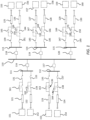
Figure 1 is a block diagram of a switch arrangement at a pole of an embodiment of a DC switch station according to the present disclosure. -
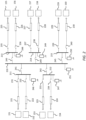
Figure 2 is a block diagram of a switch arrangement at the neutral of an embodiment of a DC switch station according to the present disclosure. -
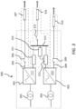
Figure 3 is a block diagram of an HVDC converter station. -
Figure 4 is a block diagram of two interconnected DC switch stations. -
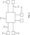
Figure 5 is a block diagram of a portion of an HVDC system. - According to the present disclosure, the DC switch station is configured for a bipolar HVDC system and comprises a common busbar of positive pole, a common busbar of negative pole, a common busbar of neutral, several sub-busbars of positive pole, several sub-busbars of negative pole, and several sub-busbars of neutral. A general structure, on a most schematic level, of a portion of the bipolar HVDC system is shown in
Figure 5 , and comprises aDC switch station 500,converter stations 501 and HVDC transmission mediums. TheDC switch station 500 is connected with theconverter stations 501 via the HVDCtransmission mediums 502. - According to an embodiment, the DC switch station comprises, at the positive pole, and at the negative pole, as shown in
Figure 1 , a common busbar ofpole 110, i.e. either positive pole or negative pole, and several sub-busbars 111-115, in the illustrated example five sub-busbars, which are each connected to the common busbar ofpole 110 via a respective high-speed DC circuit breaker 116-120. Thus, the block diagram ofFigure 1 is valid for both the positive pole and the negative pole. The high-speed DC circuit breakers 116-120 may be hybrid DC breakers or some other kind of DC circuit breakers having the capability of interrupting a high current at a high speed, i.e. within a short time from being commanded to open. As an example, an opening time for a hybrid DC breaker may be about 3 ms or less. - Each sub-busbar 111-115 may be connected to at least one HVDC transmission medium 121-130 via DC switches 131-150 having non-current interrupting capability. The transmission medium 121-130 may be, for example, an overhead transmission line or a cable. In this embodiment each sub-busbar 111-115 is connected to two HVDC transmission mediums 121-130. Each HVDC transmission medium 121-130 may further be connected to an HVDC converter station 151-160. The HVDC converter station 151-160 may also be called an HVDC terminal, and an example thereof will be briefly described below with reference to
Figure 3 . Generally, a core part of the converter station may comprise two converters, each having an alternating current (AC) side and a DC side. The AC sides are connected to the same alternating current (AC) grid or AC generator, such as, for instance, a renewable energy source, or to two different AC grids/generators. The DC sides are connected to a respective one of the positive and negative poles and in common to the neutral. - The DC switches 131-150 between each sub-busbar 111-115 of positive or negative pole and the respective HVDC transmission medium may comprise two series connected
switches current switches 132, 134, ..., 150. - Turning now to the neutral portion of the DC switch station, as illustrated in
Figure 2 , each sub-bar of neutral 211-215 may be connected to the common busbar of neutral 210 and to at least one HVDC transmission medium 221-230 via DC switches 231-245 having non-current interrupting capability, wherein each HVDC transmission medium 221-230 may further be connected to an HVDC converter station 151-160. InFigure 2 the converter stations 151-160 are given the same reference numerals as the converter stations 151-160 inFigure 1 , simply because they are the same. - Furthermore, a ground switch 246-250 may be connected between each sub-bar of neutral 211-215 and ground, and a further ground switch may be connected between the common busbar of neutral 210 and ground. The ground switches are low-speed switches having limited current interrupting capability. The internal structure of the ground switch 246-250 comprises a resonance circuit, which enables the ground switch 246-250 to interrupt a current of a certain magnitude.
- With the above exemplified switch and busbar arrangements a competent AC switch station has been obtained. For instance, the high-speed DC breakers 116-120 between the
common busbars 110 of positive and negative pole enables a faulted part to be quickly separated at the occurrence of any disturbance, thereby avoiding propagation of the disturbance to other parts of the HVDC system. Further, the DC switch station provides for a capability of performing maintenance of individual sections of the bipolar HVDC system without affecting the rest of the bipolar HVDC system. During full operation all breakers and switches, except the ground switches, are closed. Consider one of theconverter stations 151, which is connected via theHVDC transmission mediums sub-busbars 116 of positive pole, negative pole, and neutral, respectively. In order to perform maintenance on theconverter station 151, the active power and the reactive power of the converter station is reduced to zero, the converter station is blocked, and then theswitches - Depending on how the converter stations 151-160 are connected at the AC side they may be energized from the AC side or from the DC side. For instance, if the
converter station 151 is going to be energized from the DC side, then for both the positive pole and the negative pole the DC switch 132 having theresistor 161 in parallel is opened, and its series-connectedDC switch 131 is closed. When theconverter station 151 has been energized then the first-mentioned DC switch 132 is closed and theconverter station 151 can be deblocked and begin its normal operation. - Furthermore, the present DC switch station allows for switching parts of the HVDC system to operate in a point-to-point configuration. For instance, by opening, for the positive and negative poles, the
DC breaker 116 between thecommon busbar 110 and the sub-busbar 111, opening, for the neutral, theDC switch 241 between thecommon busbar 210 and the sub-busbar 211, and closing theground switch 246 between the sub-busbar 211 of neutral and ground, theconverter stations sub-busbars - Referring now to
Figure 3 , according to an example of aconverter station 300 it comprises first andsecond converters converter station 300 further comprises twoAC transformers second converters first converter 301 has a connection ofpositive pole 305, connected via aDC switch 306 to anHVDC transmission medium 307. Similarly, thesecond converter 302 has a connection ofnegative pole 308, connected via aDC switch 309 to anHVDC transmission medium 310. Further, the first andsecond converters neutral bus switch neutral busbar 313, which in turn is grounded via aground switch 314. The commonneutral busbar 313 is connected, via aDC switch 315 to anHVDC transmission medium 316. - Further, two or more DC switch stations may be interconnected, as shown in
Figure 4 , to form an even larger DC grid. The DC switch station arrangement at positive andnegative pole 401 of a first DC switch station has acommon busbar 402, which is connected via aDC breaker 403 to anHVDC transmission medium 404. The DC switch station arrangement at positive andnegative pole 405 of a second DC switch station has acommon busbar 406, which is connected via anotherDC breaker 407 to the sameHVDC transmission medium 404. The first DC switch station is connected with first converter stations 408., and the second DC switch station is connected withsecond converter stations 409. For reasons of simplicity only some of the first andsecond converter stations Figure 4 . - While the present disclosure has been illustrated and described in detail in the drawings and foregoing description, such illustration and description are to be considered illustrative or exemplary and not restrictive.
- Although features and elements are described above in particular combinations, each feature or element can be used alone without the other features and elements or in various combinations with or without other features and elements.
- Other variations to the disclosed embodiments can be understood and effected by those skilled in the art in practicing the present disclosure, from a study of the drawings, the description, and the appended claims. In the claims, the word "comprising" does not exclude other elements or steps, and the indefinite article "a" or "an" does not exclude a plurality. A single processor or other unit may fulfill the functions of several items recited in the claims. The mere fact that certain features are recited in mutually different dependent claims does not indicate that a combination of these features cannot be used to advantage. Any reference signs in the claims should not be construed as limiting the scope.
Claims (7)
- A direct current switch station configured for a bipolar high voltage direct current system, the direct current switch station comprising common busbars of positive pole, negative pole and neutral, respectively, several sub-busbars of positive pole, several sub-busbars of negative pole, and several sub-busbars of neutral, wherein each sub-busbar of positive pole and negative pole is connected to its respective common busbar via a high-speed direct current circuit breaker with high current interrupting capability, and wherein each sub-busbar of positive pole and negative pole is connected to at least one high voltage direct current transmission medium via direct current switches having non-current interrupting capability, wherein each high voltage direct current transmission medium is further connected to a high voltage direct current converter station.
- The direct current switch station according to claim 1, wherein each sub-bar of neutral is connected to the common busbar of neutral and to at least one high voltage direct current transmission medium via direct current switches having non-current interrupting capability, wherein each hvdc transmission medium is further connected to an hvdc converter.
- The direct current switch station according to any one of the preceding claims, further comprising a ground switch between each sub-bar of neutral and ground, and a ground switch between the common busbar of neutral and ground, wherein the ground switches are low-speed switches having limited current interrupting capability.
- The direct current switch station according to claim 3, wherein the ground switches comprise resonance circuits.
- The direct current switch station according to any one of the preceding claims, wherein the direct current switches between each sub-busbar of positive or negative pole and the respective high voltage direct current transmission medium comprises two series connected direct current switches, and a resistor connected in parallel with one of the series connected direct current switches.
- The direct current switch station according to any one of the preceding claims, wherein the high-speed DC circuit breaker is a hybride direct current breaker.
- The direct current switch station according to any one of the preceding claims, wherein each common busbar is connected, via a high-speed direct current circuit breaker, to a further HVDC transmission medium, which in turn is connected with a corresponding common busbar of another direct current switch station.
Priority Applications (3)
| Application Number | Priority Date | Filing Date | Title |
|---|---|---|---|
| EP23203238.3A EP4539287A1 (en) | 2023-10-12 | 2023-10-12 | A dc switch station |
| CN202480065056.7A CN122029716A (en) | 2023-10-12 | 2024-10-11 | DC switching station |
| PCT/EP2024/078740 WO2025078631A1 (en) | 2023-10-12 | 2024-10-11 | A dc switch station |
Applications Claiming Priority (1)
| Application Number | Priority Date | Filing Date | Title |
|---|---|---|---|
| EP23203238.3A EP4539287A1 (en) | 2023-10-12 | 2023-10-12 | A dc switch station |
Publications (1)
| Publication Number | Publication Date |
|---|---|
| EP4539287A1 true EP4539287A1 (en) | 2025-04-16 |
Family
ID=88412263
Family Applications (1)
| Application Number | Title | Priority Date | Filing Date |
|---|---|---|---|
| EP23203238.3A Pending EP4539287A1 (en) | 2023-10-12 | 2023-10-12 | A dc switch station |
Country Status (3)
| Country | Link |
|---|---|
| EP (1) | EP4539287A1 (en) |
| CN (1) | CN122029716A (en) |
| WO (1) | WO2025078631A1 (en) |
Citations (3)
| Publication number | Priority date | Publication date | Assignee | Title |
|---|---|---|---|---|
| US20120234796A1 (en) * | 2009-10-27 | 2012-09-20 | Abb Technology Ag | hvdc breaker and control apparatus for controlling an hvdc breaker |
| US20210119444A1 (en) * | 2018-04-27 | 2021-04-22 | General Electric Technology Gmbh | Hvdc transmission schemes |
| CN115000921A (en) * | 2022-05-07 | 2022-09-02 | 华南理工大学 | An integrated DC circuit breaker and method for handling DC faults |
Family Cites Families (2)
| Publication number | Priority date | Publication date | Assignee | Title |
|---|---|---|---|---|
| WO2012000545A1 (en) * | 2010-06-30 | 2012-01-05 | Abb Technology Ag | An hvdc transmission system, an hvdc station and a method of operating an hvdc station |
| CN110492516B (en) * | 2019-07-29 | 2020-07-14 | 南方电网科学研究院有限责任公司 | A UHV multi-terminal flexible direct current transmission converter station system and its control method |
-
2023
- 2023-10-12 EP EP23203238.3A patent/EP4539287A1/en active Pending
-
2024
- 2024-10-11 CN CN202480065056.7A patent/CN122029716A/en active Pending
- 2024-10-11 WO PCT/EP2024/078740 patent/WO2025078631A1/en active Pending
Patent Citations (3)
| Publication number | Priority date | Publication date | Assignee | Title |
|---|---|---|---|---|
| US20120234796A1 (en) * | 2009-10-27 | 2012-09-20 | Abb Technology Ag | hvdc breaker and control apparatus for controlling an hvdc breaker |
| US20210119444A1 (en) * | 2018-04-27 | 2021-04-22 | General Electric Technology Gmbh | Hvdc transmission schemes |
| CN115000921A (en) * | 2022-05-07 | 2022-09-02 | 华南理工大学 | An integrated DC circuit breaker and method for handling DC faults |
Also Published As
| Publication number | Publication date |
|---|---|
| CN122029716A (en) | 2026-05-12 |
| WO2025078631A1 (en) | 2025-04-17 |
Similar Documents
| Publication | Publication Date | Title |
|---|---|---|
| Tang et al. | Basic topology and key devices of the five-terminal DC grid | |
| Deng et al. | Operation and control of a DC-grid offshore wind farm under DC transmission system faults | |
| Adapa | High-wire act: HVdc technology: The state of the art | |
| EP3651305A1 (en) | Chained multi-port grid-connected interface apparatus and control method | |
| Zheng et al. | An integrated control and protection scheme based on FBSM-MMC active current limiting strategy for DC distribution network | |
| Koldby et al. | Challenges on the road to an offshore HVDC grid | |
| Shi et al. | Enhanced control of offshore wind farms connected to MTDC network using partially selective DC fault protection | |
| Hu et al. | Intelligent DC-DC converter based substations enable breakerless MVDC grids | |
| Liu et al. | Analysis and protection of converter-side AC faults in a cascaded converter-based MVDC link: ANGLE-DC project | |
| Qi et al. | DC power distribution: New opportunities and challenges | |
| Yuefeng et al. | Research on control and protection system for Shanghai Nanhui MMC VSC-HVDC demonstration project | |
| CN111600334B (en) | Alternating current fault diagnosis and ride-through control method for four-terminal wind power direct current power grid | |
| Saadeh et al. | Power system analysis of moving from HVAC to HVDC in the presence of renewable energy resources | |
| WO2015175346A1 (en) | Protection device for dc collection systems | |
| An et al. | Experience from the world’s first HVDC grid | |
| Zelingher et al. | Convertible static compensator project-hardware overview | |
| Haeusler et al. | HVDC solutions for integration of the renewable energy resources | |
| EP1974431B1 (en) | A converter station | |
| CN219535643U (en) | Wind power plant full-direct-current collecting and sending-out system based on multi-port direct-current transformer | |
| WO2025078631A1 (en) | A dc switch station | |
| CN110556798A (en) | A fault partition method suitable for DC power distribution system | |
| CN116231730A (en) | A full DC collecting and sending system of wind farm based on multi-port DC transformer | |
| Shi et al. | Overview of multi-terminal VSC HVDC transmission for large offshore wind farms | |
| Zhang et al. | DC Voltage Control and DC Fault Protection Scheme for Multi-Voltage Level DC Grids with High Voltage DC/DC Transformer | |
| Yuan et al. | Simulation study for a hybrid multi-terminal HVDC system |
Legal Events
| Date | Code | Title | Description |
|---|---|---|---|
| PUAI | Public reference made under article 153(3) epc to a published international application that has entered the european phase |
Free format text: ORIGINAL CODE: 0009012 |
|
| STAA | Information on the status of an ep patent application or granted ep patent |
Free format text: STATUS: THE APPLICATION HAS BEEN PUBLISHED |
|
| AK | Designated contracting states |
Kind code of ref document: A1 Designated state(s): AL AT BE BG CH CY CZ DE DK EE ES FI FR GB GR HR HU IE IS IT LI LT LU LV MC ME MK MT NL NO PL PT RO RS SE SI SK SM TR |
|
| STAA | Information on the status of an ep patent application or granted ep patent |
Free format text: STATUS: REQUEST FOR EXAMINATION WAS MADE |
|
| 17P | Request for examination filed |
Effective date: 20251016 |
|
| RIN1 | Information on inventor provided before grant (corrected) |
Inventor name: JIANG-HAEFNER, YING Inventor name: ABDALRAHMAN, ADIL Inventor name: KANNAN, VINOTHKUMAR |