EP4539277A1 - Switchgear - Google Patents
Switchgear Download PDFInfo
- Publication number
- EP4539277A1 EP4539277A1 EP23203556.8A EP23203556A EP4539277A1 EP 4539277 A1 EP4539277 A1 EP 4539277A1 EP 23203556 A EP23203556 A EP 23203556A EP 4539277 A1 EP4539277 A1 EP 4539277A1
- Authority
- EP
- European Patent Office
- Prior art keywords
- component
- guiding vanes
- guiding
- guide structure
- air guide
- Prior art date
- Legal status (The legal status is an assumption and is not a legal conclusion. Google has not performed a legal analysis and makes no representation as to the accuracy of the status listed.)
- Pending
Links
Images
Classifications
-
- H—ELECTRICITY
- H02—GENERATION; CONVERSION OR DISTRIBUTION OF ELECTRIC POWER
- H02B—BOARDS, SUBSTATIONS OR SWITCHING ARRANGEMENTS FOR THE SUPPLY OR DISTRIBUTION OF ELECTRIC POWER
- H02B1/00—Frameworks, boards, panels, desks, casings; Details of substations or switching arrangements
- H02B1/56—Cooling; Ventilation
-
- H—ELECTRICITY
- H02—GENERATION; CONVERSION OR DISTRIBUTION OF ELECTRIC POWER
- H02B—BOARDS, SUBSTATIONS OR SWITCHING ARRANGEMENTS FOR THE SUPPLY OR DISTRIBUTION OF ELECTRIC POWER
- H02B13/00—Arrangement of switchgear in which switches are enclosed in, or structurally associated with, a casing, e.g. cubicle
-
- H—ELECTRICITY
- H02—GENERATION; CONVERSION OR DISTRIBUTION OF ELECTRIC POWER
- H02G—INSTALLATION OF ELECTRIC CABLES OR LINES, OR OF COMBINED OPTICAL AND ELECTRIC CABLES OR LINES
- H02G5/00—Installations of bus-bars
- H02G5/10—Cooling
Definitions
- busbars heat up due to the passage of electrical current via Joule heating.
- the first component is a busbar.
- the first component is not oriented horizontally or vertically, but is at an angle.
- one or more of the plurality of guiding vanes are parallel to the first surface of the first component.
- the second surface of the first component is parallel to the first surface of the first component.
- one or more of the plurality of guiding vanes are parallel to the second surface of the first component.
- switchgear comprises:
- the second component is a busbar.
- the first component is adjacent to and parallel to the second component, for example two busbars one above the other with an air gap between them.
- the second component is not oriented horizontally or vertically, but is at an angle.
- one or more of the plurality of guiding vanes are parallel to the first surface of the second component.
- the first surface of the second component is flat.
- one or more of the plurality of guiding vanes are configured to direct air to enter the air guide structure at the entrance then flow tangentially to a second surface of the second component and then leave the air guide structure at the exit.
- the second surface of the second component is flat.
- one or more of the plurality of guiding vanes are parallel to the second surface of the second component.
- the upper outer guiding vane is located above the second component.
- the plurality of guiding vanes comprises a lower outer guiding vane located below the first component, and the lower outer guiding vane extends from the entrance of the guide structure to the exit of the air guide structure.
- the lower outer guiding vane is located below the second component.
- the plurality of guiding vanes comprises one or more rear guiding vanes located at the exit of the air guide structure.
- the one or more rear guiding vanes comprises a plurality of rear guiding vanes, and a honey comb structure is formed at least in part from the plurality of rear guiding vanes.
- one or more of the plurality of guiding vanes are airfoils.
- Fig. 2 relates to a new air guiding structure that is located around one or more hot components in a compartment of a switchgear.
- the first surface of the first component is flat.
- one or more of the plurality of guiding vanes are configured to direct air to enter the air guide structure at the entrance then flow tangentially to a second surface of the first component and then leave the air guide structure at the exit.
- switchgear comprises:
- the second component is a busbar.
- one or more of the plurality of guiding vanes are parallel to the first surface of the second component.
- the first surface of the second component is flat.
- the second surface of the second component is flat.
- the second component is parallel to the first component
- the plurality of guiding vanes comprises an upper outer guiding vane 30 located above the first component, and the upper outer guiding vane extends from the entrance of the guide structure to the exit of the air guide structure.
- the plurality of guiding vanes comprises one or more rear guiding vanes 60 located at the exit of the air guide structure.
- one or more of the plurality of guiding vanes are flat plates.
- one or more of the plurality of guiding vanes are airfoils.
- the airfoils are non-cambered airfoils.
- the plurality of guiding vanes are formed from an insulating material.
- the plurality of guiding vanes are formed from plastic.
- the air directed into the air guide structure come from outside of a compartment within which the components to be cooled are located and is directed out of the compartment after passing through the air guide structure.
- the air directed into the air guide structure come from outside of a compartment within which the components to be cooled are located and is directed out of the compartment after passing through the air guide structure.
- a system of outer and inner guiding vanes are attached to and/or spaced around hot components in the busbar compartment. These guiding vanes correct the air flow vector and prevent air flow separation. This system also promotes steady air flow into and out of the busbar compartment. Subsequent improvement in cooling allows designers to use less of expansive materials like copper, providing significant economical benefit.
Landscapes
- Engineering & Computer Science (AREA)
- Power Engineering (AREA)
- Cooling Or The Like Of Electrical Apparatus (AREA)
- Air-Conditioning For Vehicles (AREA)
- Structures Of Non-Positive Displacement Pumps (AREA)
Abstract
The present invention relates to a low voltage, medium voltage or high voltage switchgear, comprising:
- a first component (10); and
- an air guide structure comprising a plurality of guiding vanes (30, 40, 50, 60);
wherein the plurality of guiding vanes are located adjacent to the first component; and
wherein one or more of the plurality of guiding vanes are configured to direct air to enter the air guide structure at an entrance then flow tangentially to a first surface of the first component and then leave the air guide structure at an exit.
- a first component (10); and
- an air guide structure comprising a plurality of guiding vanes (30, 40, 50, 60);
wherein the plurality of guiding vanes are located adjacent to the first component; and
wherein one or more of the plurality of guiding vanes are configured to direct air to enter the air guide structure at an entrance then flow tangentially to a first surface of the first component and then leave the air guide structure at an exit.
Description
- The present invention relates to improved cooling of components in a low voltage, medium voltage or high voltage switchgear.
- In the low, medium and high voltage applications, components that carry current such as busbars heat up due to the passage of electrical current via Joule heating.
- These hot components must be cooled.
- A significant percentage of the cooling is sought to be achieved by air flowing over a surface of a hot component. Therefore, the ability to cool component is directly dependent upon the quantity and quality of the air flowing around the components.
- In many cases hot components are not ideally positioned relative to an airflow vector in a given location, causing flow separation. Such a phenomenon causes airflow to circulate around hot parts or to avoid a hot component completely, negatively affecting the cooling performance.
-
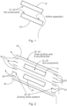
Fig. 1 shows an example of how air cannot follow an abrupt change in direction forced by a hot component, leading to flow separation. Such separation causes boundary layer detachment, formation of reverse flow and recirculation, decreasing cooling ability of air. InFig. 1 the two hot components arebusbars - In most cases the shape of such components cannot be easily modified, because the components often have shapes that serve purposes other than a shape that would be more optimum for cooling.
- There is a need to address these problems.
- Therefore, it would be advantageous to have an improved ability to cool hot components in a switchgear using air.
- The object of the present invention is solved with the subject matter of the independent claims, wherein further embodiments are incorporated in the dependent claims.
- In a first aspect, there is provided a low voltage, medium voltage or high voltage switchgear, comprising:
- a first component; and
- an air guide structure comprising a plurality of guiding vanes.
- In an example, the first component is a busbar.
- In an example, the first component is not oriented horizontally or vertically, but is at an angle.
- In an example, one or more of the plurality of guiding vanes are parallel to the first surface of the first component.
- In an example, the first surface of the first component is flat.
- In an example, one or more of the plurality of guiding vanes are configured to direct air to enter the air guide structure at the entrance then flow tangentially to a second surface of the first component and then leave the air guide structure at the exit.
- In an example, the second surface of the first component is flat.
- In an example, the second surface of the first component is parallel to the first surface of the first component.
- In an example, one or more of the plurality of guiding vanes are parallel to the second surface of the first component.
- In an example, switchgear comprises:
- a second component.
- In an example, the second component is a busbar.
- In an example, the first component is adjacent to and parallel to the second component, for example two busbars one above the other with an air gap between them.
- In an example, the second component is not oriented horizontally or vertically, but is at an angle.
- In an example, one or more of the plurality of guiding vanes are parallel to the first surface of the second component.
- In an example, the first surface of the second component is flat.
- In an example, one or more of the plurality of guiding vanes are configured to direct air to enter the air guide structure at the entrance then flow tangentially to a second surface of the second component and then leave the air guide structure at the exit.
- In an example, the second surface of the second component is flat.
- In an example, the second surface of the second component is parallel to the first surface of the first component.
- In an example, one or more of the plurality of guiding vanes are parallel to the second surface of the second component.
- In an example, the second component is parallel to the first component;
In an example, the plurality of guiding vanes comprises an upper outer guiding vane located above the first component, and the upper outer guiding vane extends from the entrance of the guide structure to the exit of the air guide structure. - In an example, the upper outer guiding vane is located above the second component.
- In an example, the plurality of guiding vanes comprises a lower outer guiding vane located below the first component, and the lower outer guiding vane extends from the entrance of the guide structure to the exit of the air guide structure.
- In an example, the lower outer guiding vane is located below the second component.
- In an example, the plurality of guiding vanes comprises one or more front guiding vanes located at the entrance of the air guide structure.
- In an example, the one or more front guiding vanes comprises a plurality of front guiding vanes, and a honey comb structure is formed at least in part from the plurality of front guiding vanes.
- In an example, the plurality of guiding vanes comprises one or more rear guiding vanes located at the exit of the air guide structure.
- In an example, the one or more rear guiding vanes comprises a plurality of rear guiding vanes, and a honey comb structure is formed at least in part from the plurality of rear guiding vanes.
- In an example, one or more of the plurality of guiding vanes are flat plates.
- In an example, one or more of the plurality of guiding vanes are airfoils.
- In an example, the airfoils are non-cambered airfoils.
- In an example, the airfoils are heavily-cambered airfoils.
- In an example, the plurality of guiding vanes are formed from an insulating material.
- In an example, the plurality of guiding vanes are formed from plastic.
- The above aspect and examples will become apparent from and be elucidated with reference to the embodiments described hereinafter.
- Exemplary embodiments will be described in the following with reference to the following drawings:
-
Fig. 1 shows a representation of airflow around hot components and airflow separation; and -
Fig. 2 shows a representation of a new air guiding structure located around hot components. -
Fig. 2 relates to a new air guiding structure that is located around one or more hot components in a compartment of a switchgear. - An exemplar new low voltage, medium voltage or high voltage switchgear comprises:
- a
first component 10; and - an air guide structure comprising a plurality of guiding
vanes - In an example, the first component is a busbar.
- In an example, the first component is not oriented horizontally or vertically, but is at an angle.
- In an example, one or more of the plurality of guiding vanes are parallel to the first surface of the first component.
- In an example, the first surface of the first component is flat.
- In an example, one or more of the plurality of guiding vanes are configured to direct air to enter the air guide structure at the entrance then flow tangentially to a second surface of the first component and then leave the air guide structure at the exit.
- In an example, the second surface of the first component is flat.
- In an example, the second surface of the first component is parallel to the first surface of the first component.
- In an example, one or more of the plurality of guiding vanes are parallel to the second surface of the first component.
- In an example, switchgear comprises:
- a
second component 20. - In an example, the second component is a busbar.
- In an example, the first component is adjacent to and parallel to the second component, for example two busbars one above the other with an air gap between them.
- In an example, the second component is not oriented horizontally or vertically, but is at an angle.
- In an example, one or more of the plurality of guiding vanes are parallel to the first surface of the second component.
- In an example, the first surface of the second component is flat.
- In an example, one or more of the plurality of guiding vanes are configured to direct air to enter the air guide structure at the entrance then flow tangentially to a second surface of the second component and then leave the air guide structure at the exit.
- In an example, the second surface of the second component is flat.
- In an example, the second surface of the second component is parallel to the first surface of the first component.
- In an example, one or more of the plurality of guiding vanes are parallel to the second surface of the second component.
- In an example, the second component is parallel to the first component;
- In an example, the plurality of guiding vanes comprises an upper
outer guiding vane 30 located above the first component, and the upper outer guiding vane extends from the entrance of the guide structure to the exit of the air guide structure. - In an example, the upper outer guiding vane is located above the second component.
- In an example, the plurality of guiding vanes comprises a lower
outer guiding vane 40 located below the first component, and the lower outer guiding vane extends from the entrance of the guide structure to the exit of the air guide structure. - In an example, the lower outer guiding vane is located below the second component.
- In an example, the plurality of guiding vanes comprises one or more
front guiding vanes 50 located at the entrance of the air guide structure. - In an example, the one or more front guiding vanes comprises a plurality of front guiding vanes, and a honey comb structure is formed at least in part from the plurality of front guiding vanes.
- In an example, the plurality of guiding vanes comprises one or more
rear guiding vanes 60 located at the exit of the air guide structure. - In an example, the one or more rear guiding vanes comprises a plurality of rear guiding vanes, and a honey comb structure is formed at least in part from the plurality of rear guiding vanes.
- In an example, one or more of the plurality of guiding vanes are flat plates.
- In an example, one or more of the plurality of guiding vanes are airfoils.
- In an example, the airfoils are non-cambered airfoils.
- In an example, the airfoils are heavily-cambered airfoils.
- In an example, the plurality of guiding vanes are formed from an insulating material.
- In an example, the plurality of guiding vanes are formed from plastic.
- In an example, the air directed into the air guide structure come from outside of a compartment within which the components to be cooled are located and is directed out of the compartment after passing through the air guide structure. Thus, not only are the hot components cooled, but the interior of the compartment as a whole is cooled.
- Thus, the new development provides for improved cooling of components inside a busbar space of low, medium or high-voltage applications.
- Conductors inside the switchgear generate heat when conducting current, and the new development provides for improved air cooling of these components.
- In particular, the conducting parts in a busbar compartment in a traditional switchgear design are relatively difficult to cool because of their shape and position inside the busbar compartment. Their shape often causes flow separation that decreases the cooling ability. The shape of the busbar compartment itself causes major flow separations, flow oscillations and disrupts steady flow of air and thus reducing cooling even further. However, the new development enables the busbars to be cooled by air.
- The new development relates to the use of a system of guiding vanes inside an aerodynamic cover. Such a system corrects an air velocity vector to make it become tangential to a hot component surface and forces air to efficiently utilize the surface of hot part to maximize cooling.
- The aerodynamic cover is formed in part from upper 30 and lower 40 guiding vanes, and the vanes inside this cover are guiding
vanes 50 at the front of the cover and guidingvanes 60 at the rear of the cover. - The
inner guiding vanes inner guiding vanes - Thus, through the new development cooling effectiveness can be significantly improved by adding air flow guiding vane system onto existing busbar designs to guide air to flow with low angle of attack relative to conductors in the busbar compartment.
- In a specific embodiment, a system of outer and inner guiding vanes are attached to and/or spaced around hot components in the busbar compartment. These guiding vanes correct the air flow vector and prevent air flow separation. This system also promotes steady air flow into and out of the busbar compartment. Subsequent improvement in cooling allows designers to use less of expansive materials like copper, providing significant economical benefit.
- It is also good practice to create the system from plastic or another insulating material, in order to avoid di-electric phenomena.
- The improved cooling means that components, such as busbars, can be made from less copper, providing economic advantages.
-
- 10
- First hot component - e.g. busbar
- 20
- Second hot component - e.g. busbar
- 30
- Upper outer guiding vane
- 40
- Lower outer guiding vane
- 50
- Front guiding vanes
- 60
- Front guiding vanes
- While the invention has been illustrated and described in detail in the drawings and foregoing description, such illustration and description are to be considered illustrative or exemplary and not restrictive. The invention is not limited to the disclosed embodiments. Other variations to the disclosed embodiments can be understood and effected by those skilled in the art in practicing a claimed invention, from a study of the drawings, the disclosure, and the dependent claims.
Claims (15)
- A low voltage, medium voltage or high voltage switchgear, comprising:- a first component (10); and- an air guide structure comprising a plurality of guiding vanes (30, 40, 50, 60);wherein the plurality of guiding vanes are located adjacent to the first component; andwherein one or more of the plurality of guiding vanes are configured to direct air to enter the air guide structure at an entrance then flow tangentially to a first surface of the first component and then leave the air guide structure at an exit.
- Switchgear according to claim 1, wherein the first surface of the first component is flat.
- Switchgear according to any of claims 1-2, the switchgear comprising:- a second component (20);wherein the second component is adjacent to the first component;wherein the plurality of guiding vanes are located adjacent to the second component; andwherein one or more of the plurality of guiding vanes are configured to direct air to enter the air guide structure at the entrance then flow tangentially to a first surface of the second component and then leave the air guide structure at the exit.
- Switchgear according to claim 3, wherein the first surface of the second component is flat.
- Switchgear according to any of claims 3-4, wherein the second component is parallel to the first component;
- Switchgear according to any of claims 1-5, wherein the plurality of guiding vanes comprises an upper outer guiding vane (30) located above the first component, and wherein the upper outer guiding vane extends from the entrance of the guide structure to the exit of the air guide structure.
- Switchgear according to claim 6 when dependent upon any of claims 3-5, wherein the upper outer guiding vane is located above the second component.
- Switchgear according to any of claims 1-7, wherein the plurality of guiding vanes comprises a lower outer guiding vane (40) located below the first component, and wherein the lower outer guiding vane extends from the entrance of the guide structure to the exit of the air guide structure.
- Switchgear according to claim 8 when dependent upon any of claims 3-7, wherein the lower outer guiding vane is located below the second component.
- Switchgear according to any of claims 1-9, wherein the plurality of guiding vanes comprises one or more front guiding vanes (50) located at the entrance of the air guide structure.
- Switchgear according to claim 10, wherein the one or more front guiding vanes comprises a plurality of front guiding vanes, and wherein a honey comb structure is formed at least in part from the plurality of front guiding vanes.
- Switchgear according to any of claims 1-11, wherein the plurality of guiding vanes comprises one or more rear guiding vanes (60) located at the exit of the air guide structure.
- Switchgear according to claim 12, wherein the one or more rear guiding vanes comprises a plurality of rear guiding vanes, and wherein a honey comb structure is formed at least in part from the plurality of rear guiding vanes.
- Switchgear according to any of claims 1-13, wherein one or more of the plurality of guiding vanes are flat plates.
- Switchgear according to any of claims 1-14, wherein one or more of the plurality of guiding vanes are airfoils.
Priority Applications (3)
| Application Number | Priority Date | Filing Date | Title |
|---|---|---|---|
| EP23203556.8A EP4539277A1 (en) | 2023-10-13 | 2023-10-13 | Switchgear |
| US18/911,391 US20250125594A1 (en) | 2023-10-13 | 2024-10-10 | Switchgear |
| CN202411422839.4A CN119834094A (en) | 2023-10-13 | 2024-10-12 | Switching device |
Applications Claiming Priority (1)
| Application Number | Priority Date | Filing Date | Title |
|---|---|---|---|
| EP23203556.8A EP4539277A1 (en) | 2023-10-13 | 2023-10-13 | Switchgear |
Publications (1)
| Publication Number | Publication Date |
|---|---|
| EP4539277A1 true EP4539277A1 (en) | 2025-04-16 |
Family
ID=88413028
Family Applications (1)
| Application Number | Title | Priority Date | Filing Date |
|---|---|---|---|
| EP23203556.8A Pending EP4539277A1 (en) | 2023-10-13 | 2023-10-13 | Switchgear |
Country Status (3)
| Country | Link |
|---|---|
| US (1) | US20250125594A1 (en) |
| EP (1) | EP4539277A1 (en) |
| CN (1) | CN119834094A (en) |
Citations (6)
| Publication number | Priority date | Publication date | Assignee | Title |
|---|---|---|---|---|
| DE29720765U1 (en) * | 1997-11-22 | 1998-01-15 | Aeg Sachsenwerk Gmbh, 93055 Regensburg | Air-cooled electrical device |
| US7272003B2 (en) * | 2003-08-13 | 2007-09-18 | Abb Research Ltd | Encapsulated switching devices having heat emission elements |
| JP2011087427A (en) * | 2009-10-16 | 2011-04-28 | Mitsubishi Electric Corp | Phase separation bus |
| CN210273437U (en) * | 2019-09-17 | 2020-04-07 | 郑州郑开电气有限公司 | Straightway bus duct and switchgear applying same |
| CN112701603A (en) * | 2021-01-25 | 2021-04-23 | 中科瑞能电气股份有限公司 | Heat dissipation switch cabinet of pull-out type |
| EP2983258B1 (en) * | 2014-08-08 | 2021-09-29 | ABB Schweiz AG | Electrical equipment and a method of manufacturing |
-
2023
- 2023-10-13 EP EP23203556.8A patent/EP4539277A1/en active Pending
-
2024
- 2024-10-10 US US18/911,391 patent/US20250125594A1/en active Pending
- 2024-10-12 CN CN202411422839.4A patent/CN119834094A/en active Pending
Patent Citations (6)
| Publication number | Priority date | Publication date | Assignee | Title |
|---|---|---|---|---|
| DE29720765U1 (en) * | 1997-11-22 | 1998-01-15 | Aeg Sachsenwerk Gmbh, 93055 Regensburg | Air-cooled electrical device |
| US7272003B2 (en) * | 2003-08-13 | 2007-09-18 | Abb Research Ltd | Encapsulated switching devices having heat emission elements |
| JP2011087427A (en) * | 2009-10-16 | 2011-04-28 | Mitsubishi Electric Corp | Phase separation bus |
| EP2983258B1 (en) * | 2014-08-08 | 2021-09-29 | ABB Schweiz AG | Electrical equipment and a method of manufacturing |
| CN210273437U (en) * | 2019-09-17 | 2020-04-07 | 郑州郑开电气有限公司 | Straightway bus duct and switchgear applying same |
| CN112701603A (en) * | 2021-01-25 | 2021-04-23 | 中科瑞能电气股份有限公司 | Heat dissipation switch cabinet of pull-out type |
Also Published As
| Publication number | Publication date |
|---|---|
| US20250125594A1 (en) | 2025-04-17 |
| CN119834094A (en) | 2025-04-15 |
Similar Documents
| Publication | Publication Date | Title |
|---|---|---|
| CN103687397B (en) | A kind of reinforcing sealed cabinet device | |
| EP3273557B1 (en) | Thermal cooling interface for electrical joints | |
| EP3089569B1 (en) | Subrack and terminal | |
| EP4539277A1 (en) | Switchgear | |
| CN108592155A (en) | Heat dissipation spit of fland body and have its oily spit of fland | |
| CN110518512A (en) | Combined trunking | |
| KR20140055599A (en) | Radiation fin attached bus bar | |
| US9362070B2 (en) | ARC extinguishing chamber for an electric protection apparatus and electric protection apparatus comprising same | |
| EP2036418B1 (en) | Electronic module configured for failure containment and system including same | |
| EP3109974B1 (en) | Systems for improved heat transfer from rotor coils | |
| CN105051853A (en) | Gas cooler for a medium voltage switchgear assembly | |
| CN203722487U (en) | Off-grid inverter device | |
| CN210273437U (en) | Straightway bus duct and switchgear applying same | |
| EP4480824A1 (en) | Chordwise ice protection heater | |
| CN221306340U (en) | Electric control cabinet and air conditioner | |
| CN206611137U (en) | A kind of vertically arranged heat sinking chip bus duct | |
| CN206673523U (en) | A kind of heat sinking chip bus duct | |
| CN206865074U (en) | A kind of vertically arranged novel air flow-guiding type bus duct | |
| US12037133B2 (en) | Shielding arrangement for aircraft wiring | |
| EP4459816A1 (en) | Low or medium voltage switchgear | |
| CN221306341U (en) | Electric control cabinet and air conditioner | |
| CN224054546U (en) | A high-efficiency heat dissipation electrical box and a range hood containing the same. | |
| CN205811484U (en) | Bus duct shell | |
| CN207936792U (en) | Radiator and cooking apparatus with it | |
| CN214848432U (en) | Series connection mechanism for direct-current large-shell-frame molded case circuit breaker |
Legal Events
| Date | Code | Title | Description |
|---|---|---|---|
| PUAI | Public reference made under article 153(3) epc to a published international application that has entered the european phase |
Free format text: ORIGINAL CODE: 0009012 |
|
| STAA | Information on the status of an ep patent application or granted ep patent |
Free format text: STATUS: THE APPLICATION HAS BEEN PUBLISHED |
|
| AK | Designated contracting states |
Kind code of ref document: A1 Designated state(s): AL AT BE BG CH CY CZ DE DK EE ES FI FR GB GR HR HU IE IS IT LI LT LU LV MC ME MK MT NL NO PL PT RO RS SE SI SK SM TR |
|
| STAA | Information on the status of an ep patent application or granted ep patent |
Free format text: STATUS: REQUEST FOR EXAMINATION WAS MADE |
|
| 17P | Request for examination filed |
Effective date: 20251007 |