EP4539261A1 - Rotatable conductor conduit assembly for dress cover - Google Patents

Rotatable conductor conduit assembly for dress cover Download PDF

Info

Publication number
EP4539261A1
EP4539261A1 EP24202124.4A EP24202124A EP4539261A1 EP 4539261 A1 EP4539261 A1 EP 4539261A1 EP 24202124 A EP24202124 A EP 24202124A EP 4539261 A1 EP4539261 A1 EP 4539261A1
Authority
EP
European Patent Office
Prior art keywords
dress cover
conduit
flange
accordance
conductor
Prior art date
Legal status (The legal status is an assumption and is not a legal conclusion. Google has not performed a legal analysis and makes no representation as to the accuracy of the status listed.)
Pending
Application number
EP24202124.4A
Other languages
German (de)
French (fr)
Inventor
Justin Kopelos
Jack Farrell
Daniel Vernon
Current Assignee (The listed assignees may be inaccurate. Google has not performed a legal analysis and makes no representation or warranty as to the accuracy of the list.)
Aptiv Technologies AG
Original Assignee
Aptiv Technologies AG
Priority date (The priority date is an assumption and is not a legal conclusion. Google has not performed a legal analysis and makes no representation as to the accuracy of the date listed.)
Filing date
Publication date
Application filed by Aptiv Technologies AG filed Critical Aptiv Technologies AG
Publication of EP4539261A1 publication Critical patent/EP4539261A1/en
Pending legal-status Critical Current

Links

Images

Classifications

    • HELECTRICITY
    • H01ELECTRIC ELEMENTS
    • H01RELECTRICALLY-CONDUCTIVE CONNECTIONS; STRUCTURAL ASSOCIATIONS OF A PLURALITY OF MUTUALLY-INSULATED ELECTRICAL CONNECTING ELEMENTS; COUPLING DEVICES; CURRENT COLLECTORS
    • H01R13/00Details of coupling devices of the kinds covered by groups H01R12/70 or H01R24/00 - H01R33/00
    • H01R13/58Means for relieving strain on wire connection, e.g. cord grip, for avoiding loosening of connections between wires and terminals within a coupling device terminating a cable
    • H01R13/5841Means for relieving strain on wire connection, e.g. cord grip, for avoiding loosening of connections between wires and terminals within a coupling device terminating a cable allowing different orientations of the cable with respect to the coupling direction
    • HELECTRICITY
    • H01ELECTRIC ELEMENTS
    • H01RELECTRICALLY-CONDUCTIVE CONNECTIONS; STRUCTURAL ASSOCIATIONS OF A PLURALITY OF MUTUALLY-INSULATED ELECTRICAL CONNECTING ELEMENTS; COUPLING DEVICES; CURRENT COLLECTORS
    • H01R13/00Details of coupling devices of the kinds covered by groups H01R12/70 or H01R24/00 - H01R33/00
    • H01R13/46Bases; Cases
    • H01R13/502Bases; Cases composed of different pieces
    • H01R13/506Bases; Cases composed of different pieces assembled by snap action of the parts
    • HELECTRICITY
    • H02GENERATION; CONVERSION OR DISTRIBUTION OF ELECTRIC POWER
    • H02GINSTALLATION OF ELECTRIC CABLES OR LINES, OR OF COMBINED OPTICAL AND ELECTRIC CABLES OR LINES
    • H02G3/00Installations of electric cables or lines or protective tubing therefor in or on buildings, equivalent structures or vehicles
    • H02G3/02Details
    • H02G3/04Protective tubing or conduits, e.g. cable ladders or cable troughs
    • H02G3/0462Tubings, i.e. having a closed section
    • H02G3/0487Tubings, i.e. having a closed section with a non-circular cross-section
    • HELECTRICITY
    • H02GENERATION; CONVERSION OR DISTRIBUTION OF ELECTRIC POWER
    • H02GINSTALLATION OF ELECTRIC CABLES OR LINES, OR OF COMBINED OPTICAL AND ELECTRIC CABLES OR LINES
    • H02G3/00Installations of electric cables or lines or protective tubing therefor in or on buildings, equivalent structures or vehicles
    • H02G3/02Details
    • H02G3/04Protective tubing or conduits, e.g. cable ladders or cable troughs
    • H02G3/0406Details thereof
    • H02G3/0418Covers or lids; Their fastenings

Definitions

  • This disclosure is directed to a dress cover for a connector of an elongate conductor, particularly to a dress cover that is rotatable to several different orientations.
  • Dress covers are used with electrical connectors to route elongate conductors, such as high speed coaxial data transmission cables, exiting the electrical connectors in a directed direction and to provide an appropriate bend radius for the conductors. A proper bend radius is especially important for data transmission cables.
  • Existing dress covers are manufactured with a fixed orientation to the connectors to which they are attached. This requires a dedicated tool to manufacture each of the dress cover orientations.
  • the dress cover 100 includes a flange 202 that is configured to be attached to an electrical connector (not shown) and an angled conductor conduit, hereafter referred to as the conduit 204, that is rotatably attached to the flange 202.
  • FIG. 1 shows the conduit 204 in a 6 o'clock orientation relative to the flange 202
  • FIG. 3 shows the conduit 204 in a 3 o'clock orientation relative to the flange 202.
  • the flange 202 has a base 402 that is configured to be secured to the electrical connector by a plurality of attaching features 404, e.g., latched locking arms, that engage a housing of the electrical connector.
  • the flange 202 also includes a hollow cylindrical collar 406 which is configured to contain the data transmission cables as they exit the electrical connector.
  • a free end 408 of the collar 406 has a circumferential ridge 410 that engages with retaining features in the conduit 204 to rotatably retain the conduit 204 to the flange 202.
  • the collar 406 also defines a plurality of slots 412 that are configured to engage with alignment features of the conduit 204 to align the conduit 204 in the desired orientation relative to the flange 202.
  • the flange 202 has two halves 414 that are joined by a living hinge 416.
  • the flange 202 also has corresponding locking features 418 on each half 414 that are configured to secure the flange 202 around the data transmission cables.
  • the flange 202 is divided into two halves 414, thereby allowing the flange 202 to be placed over the data transmission cables and attached to the electrical connector after the data transmission cables are secured within the electrical connector.
  • the collar may be of a unitary design.
  • the rotatability of the conduit 204 relative to the flange 202 of the dress cover 100 provides the benefit of allowing assembly operators to reposition the flange during assembly operations to aid installation and proper cable routing.
  • the rotatable dress cover 100 presented herein allows two components (flange 202, conduit 204) to replace up to five separate fixed dress cover components.
  • the techniques described herein relate to a dress cover, wherein the locking features include a flexible locking arm extending from the connector conduit, the flexible locking arm defining a latch on its free end and wherein the locking features further include an aperture defined by the collar and configured to receive the latch.
  • the techniques described herein relate to a dress cover, wherein the conductor conduit defines a pair of the locking arm, the latches on the pair of the locking arm being spaced at 180 degrees from one another.
  • the techniques described herein relate to a dress cover, wherein the two conduit halves are further joined by a locking loop extending from one of the two conduit halves engaging a locking tab on the other of the two conduit halves, the hinge arranged between the locking loop and the locking tab.
  • the techniques described herein relate to a dress cover, wherein the two conduit halves includes a plurality of the hinge, a plurality of the locking loop, and a plurality of the locking tab.
  • the techniques described herein relate to a dress cover, wherein the flange includes two flange halves, the two flange halves being joined by a hinge.
  • the techniques described herein relate to a dress cover, wherein the hinge includes a living hinge integrally formed with the two flange halves.
  • the techniques described herein relate to a dress cover, wherein the two flange halves are further joined by a locking loop extending from one of the two flange halves engaging a locking tab on the other of the two flange halves, the hinge arranged between the locking loop and the locking tab.
  • 'one or more' includes a function being performed by one element, a function being performed by more than one element, e.g., in a distributed fashion, several functions being performed by one element, several functions being performed by several elements, or any combination of the above.
  • first, second, etc. are, in some instances, used herein to describe various elements, these elements should not be limited by these terms. These terms are only used to distinguish one element from another.
  • a first contact could be termed a second contact, and, similarly, a second contact could be termed a first contact, without departing from the scope of the various described embodiments.
  • the first contact and the second contact are both contacts, but they are not the same contact.
  • the term “if' is, optionally, construed to mean “when” or “upon” or “in response to determining” or “in response to detecting,” depending on the context.
  • the phrase “if it is determined” or “if [a stated condition or event] is detected” is, optionally, construed to mean “upon determining” or “in response to determining” or “upon detecting [the stated condition or event]” or “in response to detecting [the stated condition or event],” depending on the context.

Landscapes

  • Engineering & Computer Science (AREA)
  • Architecture (AREA)
  • Civil Engineering (AREA)
  • Structural Engineering (AREA)
  • Connector Housings Or Holding Contact Members (AREA)
  • Details Of Indoor Wiring (AREA)
  • Details Of Connecting Devices For Male And Female Coupling (AREA)

Abstract

A dress cover (100) designed to house and guide an elongate conductor is disclosed herein. The dress cover (100) includes a flange (202) for connection to a connector and a conductor conduit (204) that is rotatably affixed to the flange (202). The conductor conduit (204) can be secured in various radial orientations with respect to the flange (202), providing flexibility in directing the conductor within the dress cover (100). This innovative design allows for efficient containment and guidance of the conductor, enhancing the functionality and versatility of the dress cover (100) in various applications.

Description

  • This disclosure is directed to a dress cover for a connector of an elongate conductor, particularly to a dress cover that is rotatable to several different orientations.
  • Dress covers are used with electrical connectors to route elongate conductors, such as high speed coaxial data transmission cables, exiting the electrical connectors in a directed direction and to provide an appropriate bend radius for the conductors. A proper bend radius is especially important for data transmission cables. Existing dress covers are manufactured with a fixed orientation to the connectors to which they are attached. This requires a dedicated tool to manufacture each of the dress cover orientations.
  • Previous approaches for containing and directing elongate conductors have typically involved fixed conduits or channels that are permanently attached to a connector or flange. These fixed conduits limit the flexibility and adjustability of the conductor's orientation, making it challenging to accommodate various installation configurations and requirements. Additionally, fixed conduits may not provide optimal positioning for the conductor, leading to potential inefficiencies or difficulties during installation and use.
  • Some existing solutions have attempted to address the limitations of fixed conduits by incorporating swivel mechanisms or adjustable joints to allow for limited rotational movement of the conduit relative to the connector. While these designs offer some degree of flexibility in positioning the conductor, they often lack the ability to securely lock the conduit in place once the desired orientation is achieved. This can result in unintended movement or misalignment of the conductor during operation, potentially leading to performance issues or safety concerns.
  • Other conventional approaches have focused on utilizing separate components or accessories to redirect or guide elongate conductors, such as clips, clamps, or brackets. However, these solutions can be cumbersome, complex, and may require additional assembly steps, increasing the overall complexity and cost of the system. Moreover, these add-on components may not provide a seamless integration with the connector or flange, leading to potential compatibility issues or inefficiencies in the overall assembly process. None of these approaches have provided a comprehensive solution that combines the features described in this disclosure.
  • In some aspects, the techniques described herein relate to a dress cover configured to contain and direct an elongate conductor, including a flange configured to be attached to a connector and a conductor conduit configured to be rotatably attached to the flange and configured to be secured in one of a plurality of radial orientations relative to the flange.
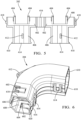
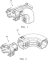
    • FIG. 1 is an isometric view of a rotatable dress cover attached to an electrical connector according to some embodiments.
    • FIG. 2 is an exploded view of the rotatable dress cover of FIG. 1 rotated to a different orientation according to some embodiments.
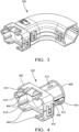
    • FIG. 3 is an isometric view of the rotatable dress cover of FIG. 1 rotated to a different orientation relative to the electrical connector according to some embodiments.
    • FIG. 4 is an isometric view of a flange of the rotatable dress cover of FIG. 1 according to some embodiments.
    • FIG. 5 is a top view of the flange of FIG. 4 in an unassembled condition according to some embodiments.
    • FIG. 6 is an isometric view of a conductor conduit of the rotatable dress cover of FIG. 1 according to some embodiments.
    • FIG. 7 is a top view of the conductor conduit of FIG. 6 in an unassembled condition according to some embodiments.
    • FIGs. 8A-8D are end views of the rotatable dress cover of FIG. 1 rotated to four different orthogonal orientations according to some embodiments.
    • FIG. 8E is an end view of the flange of FIG. 4 used as a standalone dress cover according to some embodiments.
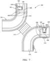
  • A non-limiting example of a rotatable dress cover 100 that can have different radial orientations is illustrated in FIG. 1 . High speed coaxial data transmission cables require a proper bend radius to maintain their designed transmission characteristics. The illustrated rotatable dress cover 100 may be used to provide the proper bend radius, volume, and exit orientation for a plurality of data transmission cables exiting an electrical connector.
  • As shown in the exploded view of FIG. 2 , the dress cover 100 includes a flange 202 that is configured to be attached to an electrical connector (not shown) and an angled conductor conduit, hereafter referred to as the conduit 204, that is rotatably attached to the flange 202. FIG. 1 shows the conduit 204 in a 6 o'clock orientation relative to the flange 202, while FIG. 3 shows the conduit 204 in a 3 o'clock orientation relative to the flange 202.
  • As illustrated in FIG.4 , the flange 202 has a base 402 that is configured to be secured to the electrical connector by a plurality of attaching features 404, e.g., latched locking arms, that engage a housing of the electrical connector. The flange 202 also includes a hollow cylindrical collar 406 which is configured to contain the data transmission cables as they exit the electrical connector. A free end 408 of the collar 406 has a circumferential ridge 410 that engages with retaining features in the conduit 204 to rotatably retain the conduit 204 to the flange 202. The collar 406 also defines a plurality of slots 412 that are configured to engage with alignment features of the conduit 204 to align the conduit 204 in the desired orientation relative to the flange 202. The slots 412 shown here are rectangular slots having a rounded bottom surface arranged around the collar 406 and spaced at substantially 90 degree intervals around the collar 406. As used herein, the term "substantially 90 degrees" means 90 degrees ± 15 degrees. Alternative embodiments of the flange may be envisioned wherein the slots have different slot and/or different spacing between the slots. For example, the alternative slots may be rectangular apertures extending through the collar 406.
  • As shown in FIGs. 4 and 5 , the flange 202 has two halves 414 that are joined by a living hinge 416. The flange 202 also has corresponding locking features 418 on each half 414 that are configured to secure the flange 202 around the data transmission cables. The flange 202 is divided into two halves 414, thereby allowing the flange 202 to be placed over the data transmission cables and attached to the electrical connector after the data transmission cables are secured within the electrical connector. In alternative embodiments, the collar may be of a unitary design.
  • As illustrated in FIG. 6 , the alignment features of the conduit 204 include a pair of locking arms 602 that are arranged substantially opposite one another, e.g., radially offset by 180 degrees ± 10 degrees. The locking arms 602 have latches 604 on one end that engage the slots 412 in the collar 406. In this example, the locking arms 602 are attached to the conduit 204 by a pair of flex beams 620 that allow the latches 604 to disengage the slots 412 by pressing on the end of the locking arms 602 opposite the latch 604. In alternative embodiments of the conduit, the locking arms may be cantilevered.
  • The retention features of the conduit 204 are a plurality of grooves 606 in an inner surface 608 of the conduit 204 in which the ridge 410 of the collar 406 is received in a "tongue-and-groove" arrangement, thereby rotatably securing the conduit 204 to the flange 202.
  • As shown in FIGs. 6 and 7 , the conduit 204 has two halves 610 that are joined by a living hinge 612. The conduit 204 also has corresponding locking features 614 on each of the two halves 610 that are configured to secure the conduit 204 around the data transmission cables and to the flange 202. The conduit 204 being divided into two halves 610 allows the conduit 204 to be placed over the data transmission cables and attached to the flange 202 after the data transmission cables are secured within the electrical connector. In alternative embodiments, the two halves 610 may be separate and secured to one another by the locking features 614 or by other means.
  • The conduit 204 has a generally octagonal cross section that provides four flat sides 616, 618 with pairs of the four flat sides 616, 618 arranged opposite one another. The four flat sides 616, 618 allow easier and better alignment for the cantilevered arms 602 with the slots 412 in the collar 406 and allow easier and better alignment for the corresponding locking features 614.
  • The conduit 204 may be oriented in a 12 o'clock position as shown in FIG. 8A , a 3 o'clock position as shown in FIG. 8B , a 6 o'clock position as shown in FIG. 8C , or a 9 o'clock position as shown in FIG. 8D . As shown in FIG. 8E , the flange 202 may be used separately to provide a dress cover with a shorter straight conduit.
  • The rotatability of the conduit 204 relative to the flange 202 of the dress cover 100 provides the benefit of allowing assembly operators to reposition the flange during assembly operations to aid installation and proper cable routing. The rotatable dress cover 100 presented herein allows two components (flange 202, conduit 204) to replace up to five separate fixed dress cover components.
  • While the conduit 204 of the dress cover 100 presented herein is bent to a right-angled shape, other embodiments of the conduit may be envisioned in which the conduit is bent to any angle between 0 and 180 degrees.
  • While the conduit 204 of the dress cover 100 presented herein is configured to be arranged at one of several predetermined orientations relative to the flange 202, other embodiment of the dress cover may be envisioned in which the conduit may be arranged in any orientation relative to the flange and is not fixed in any particular orientation.
  • While the examples presented herein are directed to a dress cover for an electrical connector, alternative embodiments of the dress cover may be envisioned that are configured for fiber optic cables, pneumatic conduits, hydraulic conduits, or a combination of any of these types of conductors.
  • Discussion of Possible Embodiments
  • In some aspects, the techniques described herein relate to a dress cover configured to contain and direct an elongate conductor, including: a flange configured to be attached to a connector; and a conductor conduit configured to be rotatably attached to the flange and configured to be secured in one of a plurality of radial orientations relative to the flange.
  • The dress cover of the preceding paragraph can optionally include, additionally and/or alternatively any, one or more of the following features/steps, configurations and/or additional components.
  • In some aspects, the techniques described herein relate to a dress cover, wherein the conductor conduit and the flange include locking features configured to secure the conductor conduit in the one of the plurality of radial orientations relative to the flange.
  • In some aspects, the techniques described herein relate to a dress cover, wherein the flange defines a cylindrical collar, and the conductor conduit defines a collar opening configured to receive the collar.
  • In some aspects, the techniques described herein relate to a dress cover, wherein a free end of the collar defines a circumferential ridge that is received in a plurality of grooves in an inner surface of the conductor conduit.
  • In some aspects, the techniques described herein relate to a dress cover, wherein the locking features include a flexible locking arm extending from the connector conduit, the flexible locking arm defining a latch on its free end and wherein the locking features further include an aperture defined by the collar and configured to receive the latch.
  • In some aspects, the techniques described herein relate to a dress cover, wherein the conductor conduit includes a curved section configured to arrange an exit opening of the conductor conduit in a non-parallel orientation to the collar opening.
  • In some aspects, the techniques described herein relate to a dress cover, wherein the collar opening has a first pair of surfaces arranged substantially parallel to one another and a second pair of surfaces arranged substantially parallel, the first pair of surfaces being arranged perpendicular to the second pair of surfaces.
  • In some aspects, the techniques described herein relate to a dress cover, wherein the collar opening has curved surfaces between each of the first pair of surfaces and the second pair of surfaces.
  • In some aspects, the techniques described herein relate to a dress cover, wherein one of the first pair of surfaces defines the flexible locking arm.
  • In some aspects, the techniques described herein relate to a dress cover, wherein the collar defines a plurality of the aperture arranged around the collar and spaced to provide one of the plurality of radial orientations of the conductor conduit relative to the flange.
  • In some aspects, the techniques described herein relate to a dress cover, wherein the collar defines four apertures in the plurality of the aperture spaced at 90 degrees from one another.
  • In some aspects, the techniques described herein relate to a dress cover, wherein the conductor conduit defines a plurality of the locking arm arranged around the conductor conduit and spaced to provide one of the plurality of radial orientations of the conductor conduit relative to the flange.
  • In some aspects, the techniques described herein relate to a dress cover, wherein the conductor conduit defines a pair of the locking arm, the latches on the pair of the locking arm being spaced at 180 degrees from one another.
  • In some aspects, the techniques described herein relate to a dress cover, wherein the conductor conduit includes two conduit halves, the two conduit halves being joined by a hinge.
  • In some aspects, the techniques described herein relate to a dress cover, wherein the hinge includes a living hinge integrally formed with the two conduit halves.
  • In some aspects, the techniques described herein relate to a dress cover, wherein the two conduit halves are further joined by a locking loop extending from one of the two conduit halves engaging a locking tab on the other of the two conduit halves, the hinge arranged between the locking loop and the locking tab.
  • In some aspects, the techniques described herein relate to a dress cover, wherein the two conduit halves includes a plurality of the hinge, a plurality of the locking loop, and a plurality of the locking tab.
  • In some aspects, the techniques described herein relate to a dress cover, wherein the flange includes two flange halves, the two flange halves being joined by a hinge.
  • In some aspects, the techniques described herein relate to a dress cover, wherein the hinge includes a living hinge integrally formed with the two flange halves.
  • In some aspects, the techniques described herein relate to a dress cover, wherein the two flange halves are further joined by a locking loop extending from one of the two flange halves engaging a locking tab on the other of the two flange halves, the hinge arranged between the locking loop and the locking tab.
  • While the invention has been described with reference to an exemplary embodiment(s), it will be understood by those skilled in the art that various changes may be made, and equivalents may be substituted for elements thereof without departing from the scope of the invention. In addition, many modifications may be made to adapt a particular situation or material to the teachings of the invention without departing from the essential scope thereof. Therefore, it is intended that the invention is not limited to the disclosed embodiment(s), but that the invention will include all embodiments falling within the scope of the appended claims.
  • As used herein, 'one or more' includes a function being performed by one element, a function being performed by more than one element, e.g., in a distributed fashion, several functions being performed by one element, several functions being performed by several elements, or any combination of the above.
  • It will also be understood that, although the terms first, second, etc. are, in some instances, used herein to describe various elements, these elements should not be limited by these terms. These terms are only used to distinguish one element from another. For example, a first contact could be termed a second contact, and, similarly, a second contact could be termed a first contact, without departing from the scope of the various described embodiments. The first contact and the second contact are both contacts, but they are not the same contact.
  • The terminology used in the description of the various described embodiments herein is for the purpose of describing particular embodiments only and is not intended to be limiting. As used in the description of the various described embodiments and the appended claims, the singular forms "a", "an" and "the" are intended to include the plural forms as well, unless the context clearly indicates otherwise. It will also be understood that the term "and/or" as used herein refers to and encompasses any and all possible combinations of one or more of the associated listed items. It will be further understood that the terms "includes," "including," "comprises," and/or "comprising," when used in this specification, specify the presence of stated features, integers, steps, operations, elements, and/or components, but do not preclude the presence or addition of one or more other features, integers, steps, operations, elements, components, and/or groups thereof.
  • As used herein, the term "if' is, optionally, construed to mean "when" or "upon" or "in response to determining" or "in response to detecting," depending on the context. Similarly, the phrase "if it is determined" or "if [a stated condition or event] is detected" is, optionally, construed to mean "upon determining" or "in response to determining" or "upon detecting [the stated condition or event]" or "in response to detecting [the stated condition or event]," depending on the context.
  • Additionally, while terms of ordinance or orientation may be used herein these elements should not be limited by these terms. All terms of ordinance or orientation, unless stated otherwise, are used for purposes distinguishing one element from another, and do not denote any particular order, order of operations, direction or orientation unless stated otherwise.
Claims (15)

  1. A dress cover (100) configured to contain and direct an elongate conductor, comprising:
    a flange (202) configured to be attached to a connector; and
    a conductor conduit (204) configured to be rotatably attached to the flange (202) and configured to be secured in one of a plurality of radial orientations relative to the flange (202).
  2. The dress cover (100) in accordance with claim 1, wherein the conductor conduit (204) and the flange (202) comprise locking features (404) configured to secure the conductor conduit (204) in the one of the plurality of radial orientations relative to the flange (202).
  3. The dress cover (100) in accordance with claim 2, wherein the flange (202) defines a cylindrical collar (406), and the conductor conduit (204) defines a collar opening configured to receive the collar (406).
  4. The dress cover (100) in accordance with claim 3, wherein a free end (408) of the collar (406) defines a circumferential ridge (410) that is received in a plurality of grooves (606) in an inner surface (608) of the conductor conduit (204).
  5. The dress cover (100) in accordance with claim 4, wherein the locking features (404) comprise a flexible locking arm (602) extending from the connector conduit (204), the flexible locking arm (620) defining a latch (604) on its free end (408) and wherein the locking features (404) further comprise an aperture (412) defined by the collar (406) and configured to receive the latch (604).
  6. The dress cover (100) in accordance with claim 5, wherein the collar opening has a first pair of surfaces (618) arranged substantially parallel to one another and a second pair of surfaces (616) arranged substantially parallel, the first pair of surfaces (618) being arranged perpendicular to the second pair of surfaces (616).
  7. The dress cover (100) in accordance with claim 6, wherein the collar opening has curved surfaces between each of the first pair of surfaces (618) and the second pair of surfaces (616).
  8. The dress cover (100) in accordance with claim 6 or 7, wherein one of the first pair of surfaces (618) defines the flexible locking arm (602).
  9. The dress cover (100) in accordance with any one of claims 5 to 8, wherein the collar (406) defines a plurality of the aperture (412) arranged around the collar (406) and spaced to provide one of the plurality of radial orientations of the conductor conduit (204) relative to the flange (202).
  10. The dress cover (100) in accordance with claim 9, wherein the collar (406) defines four apertures in the plurality of the aperture (412) spaced at 90 degrees from one another.
  11. The dress cover (100) in accordance with claim 9 or 10, wherein the conductor conduit (204) defines a plurality of the locking arm (602) arranged around the conductor conduit (204) and spaced to provide one of the plurality of radial orientations of the conductor conduit (204) relative to the flange (202).
  12. The dress cover (100) in accordance with claim 11, wherein the conductor conduit (204) defines a pair of the locking arm (602), the latches (604) on the pair of the locking arm (602) being spaced at 180 degrees from one another.
  13. The dress cover (100) in accordance with any one of claims 4 to 12, wherein the conductor conduit (204) comprises a curved section configured to arrange an exit opening of the conductor conduit (204) in a non-parallel orientation to the collar opening.
  14. The dress cover (100) in accordance with any one of the preceding claims, wherein the conductor conduit (204) comprises two conduit (204) halves, the two conduit halves (610) being joined by a hinge (612).
  15. The dress cover (100) in accordance with claim 14, wherein the hinge (612) comprises a living hinge integrally formed with the two conduit halves (610).
EP24202124.4A 2023-10-10 2024-09-24 Rotatable conductor conduit assembly for dress cover Pending EP4539261A1 (en)

Applications Claiming Priority (2)

Application Number Priority Date Filing Date Title
US202363543361P 2023-10-10 2023-10-10
US18/888,546 US20250118924A1 (en) 2023-10-10 2024-09-18 Rotatable conductor conduit assembly for dress cover

Publications (1)

Publication Number Publication Date
EP4539261A1 true EP4539261A1 (en) 2025-04-16

Family

ID=92899979

Family Applications (1)

Application Number Title Priority Date Filing Date
EP24202124.4A Pending EP4539261A1 (en) 2023-10-10 2024-09-24 Rotatable conductor conduit assembly for dress cover

Country Status (3)

Country Link
US (1) US20250118924A1 (en)
EP (1) EP4539261A1 (en)
CN (1) CN119812821A (en)

Citations (4)

* Cited by examiner, † Cited by third party
Publication number Priority date Publication date Assignee Title
FR2712740A1 (en) * 1993-11-19 1995-05-24 Sylea Guide device for guiding series of electrical conductors leaving rear of connector
DE102007029593A1 (en) * 2007-06-27 2009-01-08 Fränkische Rohrwerke Gebr. Kirchner GmbH + Co. KG Plug protection cap has extension element that is fixed at basic element with respect to relative rotation between each other towards extending direction of plug retaining section, particularly parallel running axle
US7494376B1 (en) * 2008-03-10 2009-02-24 Tyco Electronics Corporation Multiple direction wire cover with positioning latch and position assurance lock
EP3758160A1 (en) * 2019-06-28 2020-12-30 Aptiv Technologies Limited Connector shell with an orientable conduit, method for mounting a connector and connector equipped with this shell

Patent Citations (4)

* Cited by examiner, † Cited by third party
Publication number Priority date Publication date Assignee Title
FR2712740A1 (en) * 1993-11-19 1995-05-24 Sylea Guide device for guiding series of electrical conductors leaving rear of connector
DE102007029593A1 (en) * 2007-06-27 2009-01-08 Fränkische Rohrwerke Gebr. Kirchner GmbH + Co. KG Plug protection cap has extension element that is fixed at basic element with respect to relative rotation between each other towards extending direction of plug retaining section, particularly parallel running axle
US7494376B1 (en) * 2008-03-10 2009-02-24 Tyco Electronics Corporation Multiple direction wire cover with positioning latch and position assurance lock
EP3758160A1 (en) * 2019-06-28 2020-12-30 Aptiv Technologies Limited Connector shell with an orientable conduit, method for mounting a connector and connector equipped with this shell

Also Published As

Publication number Publication date
US20250118924A1 (en) 2025-04-10
CN119812821A (en) 2025-04-11

Similar Documents

Publication Publication Date Title
US20080128164A1 (en) Conduit connector assembly
US5908327A (en) Electrical connector with cover assembly
US7576290B1 (en) Electrical cable connector assembly and retaining spring
US6220889B1 (en) Adjustable cable egress mechanism for cable connectors
US6049040A (en) Universal cable guide
US6934456B2 (en) Cable trough cover
US11662041B2 (en) Support clip
CN109565168A (en) Hanger for mounting cable
EP3319191B1 (en) Articulated guide for cables
US10677377B2 (en) Conduit clip and conduit clip arrangement with a conduit clip and a conduit
US6459038B1 (en) Two-piece up-spout fitting for wiring duct
US6450834B1 (en) Panel mounting system for electrical connectors
CN114868058B (en) Terminal system components with branch/adapter modules
JPH1027646A (en) Connector
US10483735B1 (en) Ninety degree snap fit electrical fitting for connection of electrical cables to an electrical box
US6968864B2 (en) Rotary holder for corrugated tube
AU683991B2 (en) A cable routing device
EP0641047A1 (en) Connector assembly for a photoelectric sensor
JP2021173417A (en) Female connector and connector assembly
EP4539261A1 (en) Rotatable conductor conduit assembly for dress cover
CN104470688B (en) structure for robot
US7022914B1 (en) Electrical connectors
JPH10133060A (en) Optical fiber connector device
US11387639B2 (en) Electrical box cable connector
US5390968A (en) Flat elbow/one direction tee fitting

Legal Events

Date Code Title Description
PUAI Public reference made under article 153(3) epc to a published international application that has entered the european phase

Free format text: ORIGINAL CODE: 0009012

STAA Information on the status of an ep patent application or granted ep patent

Free format text: STATUS: THE APPLICATION HAS BEEN PUBLISHED

AK Designated contracting states

Kind code of ref document: A1

Designated state(s): AL AT BE BG CH CY CZ DE DK EE ES FI FR GB GR HR HU IE IS IT LI LT LU LV MC ME MK MT NL NO PL PT RO RS SE SI SK SM TR

STAA Information on the status of an ep patent application or granted ep patent

Free format text: STATUS: REQUEST FOR EXAMINATION WAS MADE

17P Request for examination filed

Effective date: 20250603