EP4539243A1 - Battery cell, battery, and electric device - Google Patents
Battery cell, battery, and electric device Download PDFInfo
- Publication number
- EP4539243A1 EP4539243A1 EP23838621.3A EP23838621A EP4539243A1 EP 4539243 A1 EP4539243 A1 EP 4539243A1 EP 23838621 A EP23838621 A EP 23838621A EP 4539243 A1 EP4539243 A1 EP 4539243A1
- Authority
- EP
- European Patent Office
- Prior art keywords
- connecting portion
- tab
- battery cell
- face
- electrode terminal
- Prior art date
- Legal status (The legal status is an assumption and is not a legal conclusion. Google has not performed a legal analysis and makes no representation as to the accuracy of the status listed.)
- Pending
Links
Images



Classifications
-
- H—ELECTRICITY
- H01—ELECTRIC ELEMENTS
- H01M—PROCESSES OR MEANS, e.g. BATTERIES, FOR THE DIRECT CONVERSION OF CHEMICAL ENERGY INTO ELECTRICAL ENERGY
- H01M50/00—Constructional details or processes of manufacture of the non-active parts of electrochemical cells other than fuel cells, e.g. hybrid cells
- H01M50/50—Current conducting connections for cells or batteries
- H01M50/531—Electrode connections inside a battery casing
-
- H—ELECTRICITY
- H01—ELECTRIC ELEMENTS
- H01M—PROCESSES OR MEANS, e.g. BATTERIES, FOR THE DIRECT CONVERSION OF CHEMICAL ENERGY INTO ELECTRICAL ENERGY
- H01M50/00—Constructional details or processes of manufacture of the non-active parts of electrochemical cells other than fuel cells, e.g. hybrid cells
- H01M50/20—Mountings; Secondary casings or frames; Racks, modules or packs; Suspension devices; Shock absorbers; Transport or carrying devices; Holders
- H01M50/204—Racks, modules or packs for multiple batteries or multiple cells
- H01M50/207—Racks, modules or packs for multiple batteries or multiple cells characterised by their shape
- H01M50/209—Racks, modules or packs for multiple batteries or multiple cells characterised by their shape adapted for prismatic or rectangular cells
-
- H—ELECTRICITY
- H01—ELECTRIC ELEMENTS
- H01M—PROCESSES OR MEANS, e.g. BATTERIES, FOR THE DIRECT CONVERSION OF CHEMICAL ENERGY INTO ELECTRICAL ENERGY
- H01M10/00—Secondary cells; Manufacture thereof
- H01M10/04—Construction or manufacture in general
-
- H—ELECTRICITY
- H01—ELECTRIC ELEMENTS
- H01M—PROCESSES OR MEANS, e.g. BATTERIES, FOR THE DIRECT CONVERSION OF CHEMICAL ENERGY INTO ELECTRICAL ENERGY
- H01M50/00—Constructional details or processes of manufacture of the non-active parts of electrochemical cells other than fuel cells, e.g. hybrid cells
- H01M50/10—Primary casings; Jackets or wrappings
- H01M50/102—Primary casings; Jackets or wrappings characterised by their shape or physical structure
- H01M50/103—Primary casings; Jackets or wrappings characterised by their shape or physical structure prismatic or rectangular
-
- H—ELECTRICITY
- H01—ELECTRIC ELEMENTS
- H01M—PROCESSES OR MEANS, e.g. BATTERIES, FOR THE DIRECT CONVERSION OF CHEMICAL ENERGY INTO ELECTRICAL ENERGY
- H01M50/00—Constructional details or processes of manufacture of the non-active parts of electrochemical cells other than fuel cells, e.g. hybrid cells
- H01M50/40—Separators; Membranes; Diaphragms; Spacing elements inside cells
- H01M50/471—Spacing elements inside cells other than separators, membranes or diaphragms; Manufacturing processes thereof
- H01M50/474—Spacing elements inside cells other than separators, membranes or diaphragms; Manufacturing processes thereof characterised by their position inside the cells
-
- H—ELECTRICITY
- H01—ELECTRIC ELEMENTS
- H01M—PROCESSES OR MEANS, e.g. BATTERIES, FOR THE DIRECT CONVERSION OF CHEMICAL ENERGY INTO ELECTRICAL ENERGY
- H01M50/00—Constructional details or processes of manufacture of the non-active parts of electrochemical cells other than fuel cells, e.g. hybrid cells
- H01M50/40—Separators; Membranes; Diaphragms; Spacing elements inside cells
- H01M50/471—Spacing elements inside cells other than separators, membranes or diaphragms; Manufacturing processes thereof
- H01M50/477—Spacing elements inside cells other than separators, membranes or diaphragms; Manufacturing processes thereof characterised by their shape
-
- H—ELECTRICITY
- H01—ELECTRIC ELEMENTS
- H01M—PROCESSES OR MEANS, e.g. BATTERIES, FOR THE DIRECT CONVERSION OF CHEMICAL ENERGY INTO ELECTRICAL ENERGY
- H01M50/00—Constructional details or processes of manufacture of the non-active parts of electrochemical cells other than fuel cells, e.g. hybrid cells
- H01M50/50—Current conducting connections for cells or batteries
- H01M50/528—Fixed electrical connections, i.e. not intended for disconnection
-
- H—ELECTRICITY
- H01—ELECTRIC ELEMENTS
- H01M—PROCESSES OR MEANS, e.g. BATTERIES, FOR THE DIRECT CONVERSION OF CHEMICAL ENERGY INTO ELECTRICAL ENERGY
- H01M50/00—Constructional details or processes of manufacture of the non-active parts of electrochemical cells other than fuel cells, e.g. hybrid cells
- H01M50/50—Current conducting connections for cells or batteries
- H01M50/531—Electrode connections inside a battery casing
- H01M50/533—Electrode connections inside a battery casing characterised by the shape of the leads or tabs
-
- H—ELECTRICITY
- H01—ELECTRIC ELEMENTS
- H01M—PROCESSES OR MEANS, e.g. BATTERIES, FOR THE DIRECT CONVERSION OF CHEMICAL ENERGY INTO ELECTRICAL ENERGY
- H01M50/00—Constructional details or processes of manufacture of the non-active parts of electrochemical cells other than fuel cells, e.g. hybrid cells
- H01M50/50—Current conducting connections for cells or batteries
- H01M50/531—Electrode connections inside a battery casing
- H01M50/536—Electrode connections inside a battery casing characterised by the method of fixing the leads to the electrodes, e.g. by welding
-
- H—ELECTRICITY
- H01—ELECTRIC ELEMENTS
- H01M—PROCESSES OR MEANS, e.g. BATTERIES, FOR THE DIRECT CONVERSION OF CHEMICAL ENERGY INTO ELECTRICAL ENERGY
- H01M50/00—Constructional details or processes of manufacture of the non-active parts of electrochemical cells other than fuel cells, e.g. hybrid cells
- H01M50/50—Current conducting connections for cells or batteries
- H01M50/543—Terminals
- H01M50/547—Terminals characterised by the disposition of the terminals on the cells
- H01M50/55—Terminals characterised by the disposition of the terminals on the cells on the same side of the cell
-
- H—ELECTRICITY
- H01—ELECTRIC ELEMENTS
- H01M—PROCESSES OR MEANS, e.g. BATTERIES, FOR THE DIRECT CONVERSION OF CHEMICAL ENERGY INTO ELECTRICAL ENERGY
- H01M50/00—Constructional details or processes of manufacture of the non-active parts of electrochemical cells other than fuel cells, e.g. hybrid cells
- H01M50/50—Current conducting connections for cells or batteries
- H01M50/543—Terminals
- H01M50/552—Terminals characterised by their shape
- H01M50/553—Terminals adapted for prismatic, pouch or rectangular cells
-
- H—ELECTRICITY
- H01—ELECTRIC ELEMENTS
- H01M—PROCESSES OR MEANS, e.g. BATTERIES, FOR THE DIRECT CONVERSION OF CHEMICAL ENERGY INTO ELECTRICAL ENERGY
- H01M50/00—Constructional details or processes of manufacture of the non-active parts of electrochemical cells other than fuel cells, e.g. hybrid cells
- H01M50/50—Current conducting connections for cells or batteries
- H01M50/572—Means for preventing undesired use or discharge
- H01M50/584—Means for preventing undesired use or discharge for preventing incorrect connections inside or outside the batteries
- H01M50/586—Means for preventing undesired use or discharge for preventing incorrect connections inside or outside the batteries inside the batteries, e.g. incorrect connections of electrodes
-
- H—ELECTRICITY
- H01—ELECTRIC ELEMENTS
- H01M—PROCESSES OR MEANS, e.g. BATTERIES, FOR THE DIRECT CONVERSION OF CHEMICAL ENERGY INTO ELECTRICAL ENERGY
- H01M50/00—Constructional details or processes of manufacture of the non-active parts of electrochemical cells other than fuel cells, e.g. hybrid cells
- H01M50/50—Current conducting connections for cells or batteries
- H01M50/572—Means for preventing undesired use or discharge
- H01M50/584—Means for preventing undesired use or discharge for preventing incorrect connections inside or outside the batteries
- H01M50/59—Means for preventing undesired use or discharge for preventing incorrect connections inside or outside the batteries characterised by the protection means
- H01M50/593—Spacers; Insulating plates
-
- H—ELECTRICITY
- H01—ELECTRIC ELEMENTS
- H01M—PROCESSES OR MEANS, e.g. BATTERIES, FOR THE DIRECT CONVERSION OF CHEMICAL ENERGY INTO ELECTRICAL ENERGY
- H01M2220/00—Batteries for particular applications
- H01M2220/20—Batteries in motive systems, e.g. vehicle, ship, plane
-
- Y—GENERAL TAGGING OF NEW TECHNOLOGICAL DEVELOPMENTS; GENERAL TAGGING OF CROSS-SECTIONAL TECHNOLOGIES SPANNING OVER SEVERAL SECTIONS OF THE IPC; TECHNICAL SUBJECTS COVERED BY FORMER USPC CROSS-REFERENCE ART COLLECTIONS [XRACs] AND DIGESTS
- Y02—TECHNOLOGIES OR APPLICATIONS FOR MITIGATION OR ADAPTATION AGAINST CLIMATE CHANGE
- Y02E—REDUCTION OF GREENHOUSE GAS [GHG] EMISSIONS, RELATED TO ENERGY GENERATION, TRANSMISSION OR DISTRIBUTION
- Y02E60/00—Enabling technologies; Technologies with a potential or indirect contribution to GHG emissions mitigation
- Y02E60/10—Energy storage using batteries
Definitions
- This application pertains to the field of battery technologies, and in particular, to a battery cell, a battery, and an electric apparatus.
- the battery cells can be combined into a system for using new renewable energy.
- Embodiments of this application provide a battery cell, a battery, and an electric apparatus, which implement direct connection between a tab and an electrode terminal, thereby increasing the energy density of the battery.
- an embodiment of this application provides a battery cell, including a housing, an electrode terminal, and an electrode assembly.
- the electrode terminal is disposed on the housing, and the electrode assembly is accommodated in the housing.
- the electrode assembly includes a main body portion and a tab, the tab extends out of an end face of the main body portion, the tab includes a first connecting portion and a second connecting portion, the first connecting portion is configured to be connected to the electrode terminal, and the second connecting portion is configured to be connected to the main body portion.
- the first connecting portion is configured to be connected to the electrode terminal
- the second connecting portion is configured to be connected to the main body portion.
- the connectable range of the first connecting portion in the length direction of the end face can be expanded, facilitating direct connection of the first connecting portion with the electrode terminal. This optimizes the internal structure of the battery cell, increases the available space for the electrode assembly, and increases the energy density of the battery cell.
- the first connecting portion is connected to the electrode terminal to form a connection region, and along a length direction of the end face, at least part of the connection region exceeds the second connecting portion.
- connection region exceeds the second connecting portion along the length direction of the end face, a connection position between the first connecting portion and the electrode terminal can be on an exceeding portion of the first connecting portion. Even if a position where the tab is led out is not aligned with the electrode terminal, the tab can still be connected to the electrode terminal via the part of the first connecting portion exceeding the second connecting portion.
- a size of the first connecting portion is greater than a size of the second connecting portion.
- the first connecting portion can obtain a larger area, facilitating connection to the electrode terminal.
- a notch is provided at a joint between the second connecting portion and the main body portion.
- the arrangement of the notch can shrink a size of a connection position of the second connecting portion to the main body portion, increasing a distance between the second connecting portion and another component in the battery cell (for example, an insulating plate between the electrode assembly and the first wall), thereby avoiding interference between the second connecting portion and other components.
- the tab is L-shaped or T-shaped.
- the size of the first connecting portion in the length direction of the end face can be significantly increased, facilitating connection of the tab with the electrode terminal. This also significantly reduces the size of the second connecting portion in the length direction of the end face, preventing the second connecting portion from contacting the protruding block.
- the tab includes a positive electrode tab and a negative electrode tab, the positive electrode tab and the negative electrode tab are both located on the end face, the positive electrode tab and the negative electrode tab each include a first connecting portion and a second connecting portion, and the first connecting portion of the positive electrode tab and the first connecting portion of the negative electrode tab extend in opposite directions.
- the tab can meet the setting requirements of different types of electrode terminals.
- the two first connecting portions extend in directions approaching each other.
- the electrode terminal is located on both sides of the second connecting portions of the positive electrode tab and the negative electrode tab, the two first connecting portions extend in directions back away from each other.
- the housing includes a first wall, the electrode terminal is disposed on the first wall, and the end face faces the first wall.
- the electrode terminal is located at one end of the first wall, and the positive electrode tab and the negative electrode tab extend in directions leaving each other.
- the lead-out positions of the positive electrode tab and the negative electrode tab on the end face can be gathered towards the center, reducing interference of the positive electrode tab and the negative electrode tab with components on both sides.
- This furthermore allows for a greater spacing between connection regions on the positive electrode tab and the negative electrode tab, thereby improving the safety of the battery cell.
- the first wall is also provided with an insulating plate on a side facing the electrode assembly, and the insulating plate is configured to insulate the first wall from the electrode assembly.
- limiting the relative distance between the protruding block and the second connecting portion can significantly reduce the problem of short circuit caused by mutual squeezing and abutting between the second connecting portion and the protruding block.
- the first connecting portion is bent relative to the second connecting portion.
- bending the first connecting portion and the second connecting portion can reduce the space occupied by the tabs, thereby increasing the energy density of the battery cell.
- an embodiment of this application provides a battery, including the foregoing battery cell.
- the term "and/or" is only an associative relationship for describing associated objects, indicating that three relationships may be present.
- a and/or B may indicate the following three cases: presence of only A, presence of both A and B, and presence of only B.
- the character "/" in this specification generally indicates an "or" relationship between contextually associated objects.
- multiple means more than two (inclusive).
- multiple groups means more than two (inclusive) groups
- multiple pieces means more than two (inclusive) pieces.
- the technical terms “mounting”, “connection”, “join”, and “fastening” should be understood in their general senses. For example, they may refer to a fixed connection, a detachable connection, or an integral connection, may refer to a mechanical connection or an electrical connection, and may refer to a direct connection, an indirect connection through an intermediary, an internal communication between two elements, or an interaction between two elements. Persons of ordinary skills in the art can understand specific meanings of these terms in this application as appropriate to specific situations.
- a battery cell typically includes a housing and an electrode assembly, where the electrode assembly is a crucial part for completing the electrochemical process of the battery. It usually consists of electrode plates and a separator, with the electrode plates including a positive electrode plate and a negative electrode plate.
- the positive electrode plate and negative electrode plate each include a current collector and an active material layer applied to it.
- the electrochemical process mainly relies on the movement of metal ions, such as lithium ions, between the positive electrode plate and negative electrode plate within the active material layer. Therefore, the energy density of a battery cell is closely related to the volume ratio of the electrode assembly.
- an electrode terminal needs to be disposed on the housing.
- a side of the electrode terminal near the inside of the housing needs to be connected to the electrode assembly.
- a tab is arranged to be connected with the electrode terminal.
- a connecting component is usually used to connect the tab with the electrode terminal.
- arranging the connecting component additionally occupies the space in the housing, reducing the space available for the electrode assembly and thus decreasing the energy density of the battery cell.
- the inventors found that adjusting the structure of the tab can efficiently connect the tab to the electrode terminal without a connecting component. This reduces the internal structure of the housing and increases the space available for the electrode assembly, thereby increasing the energy density of the battery.
- the inventors of this application have conducted in-depth research and designed a battery cell, a battery, and an electric apparatus.
- An embodiment of this application provides an electric apparatus that uses a battery as a power source.
- the electric apparatus may be but is not limited to a mobile phone, a tablet, a notebook computer, an electric toy, an electric tool, an electric bicycle, an electric car, a ship, or a spacecraft.
- the electric toy may include a fixed or mobile electric toy, for example, a game console, an electric toy car, an electric toy ship, and an electric toy airplane.
- the spacecraft may include an airplane, a rocket, a space shuttle, a spaceship, and the like.
- the electric apparatus of an embodiment of this application being a vehicle 1000 is used as an example for description of the following embodiments.
- FIG. 1 is a schematic structural diagram of a vehicle 1000 according to some embodiments of this application.
- the vehicle 1000 may be a fossil fuel vehicle, a natural-gas vehicle, or a new energy vehicle, where the new energy vehicle may be a battery electric vehicle, a hybrid electric vehicle, a range-extended vehicle, or the like.
- the vehicle 1000 is provided with a battery 100 inside, where the battery 100 may be disposed at the bottom, front or rear of the vehicle 1000.
- the battery 100 may be configured to supply power to the vehicle 1000.
- the battery 100 may be used as an operational power source for the vehicle 1000.
- the vehicle 1000 may further include a controller 200 and a motor 300, where the controller 200 is configured to control the battery 100 to supply power to the motor 300, for example, to satisfy power needs of start, navigation, and driving of the vehicle 1000.
- the battery 100 can be used as not only the operational power source for the vehicle 1000 but also a driving power source for the vehicle 1000, replacing or partially replacing fossil fuel or natural gas to provide driving traction for the vehicle 1000.
- the battery mentioned in the embodiments of this application is a single physical module that includes one or more battery cells for providing higher voltage and capacity.
- the battery mentioned in this application may include a battery module, a battery pack, or the like.
- FIG. 2 is a schematic structural diagram of a battery 100 according to some embodiments of this application.
- the battery 100 includes a box 110.
- the box 110 may include a first box portion 111 and a second box portion 112 connected together. After connected in parallel, in series, or in parallel and series, multiple battery cells are placed in the space formed by the first box portion 111 and the second box portion 112 through connection.
- the shapes of the first box portion 111 and the second box portion 112 can be determined according to the shape formed by combined multiple battery cells.
- the battery cell may be cylindrical, flat, rectangular, or of other shapes. This embodiment of this application does not limit this.
- the battery cells include but are not limited to cylindrical battery cells, prismatic battery cells, and pouch battery cells. This embodiment of this application does not limit this.
- the battery 100 may further include other structures, such as a busbar component configured to achieve electrical connection between multiple battery cells, which is detailed herein.
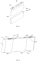
- FIG. 3 is a schematic structural diagram of a battery cell according to some embodiments of this application
- FIG. 4 is a schematic structural diagram of an electrode assembly 103 according to some embodiments of this application.
- some embodiments of this application provide a battery cell 10, including a housing 101, an electrode terminal 102, and an electrode assembly 103.
- the electrode terminal 102 is disposed on the housing 101, and the electrode assembly 103 is accommodated in the housing 101.
- the electrode assembly 103 includes a main body portion 1 and a tab 2, the tab 2 extends out of an end face 11 of the main body portion 1, the tab 2 includes a first connecting portion 21 and a second connecting portion 22, the first connecting portion 21 is configured to be connected to the electrode terminal 102, and the second connecting portion 22 is configured to be connected to the main body portion 1.
- a length direction an x-axis direction in FIG. 4
- at least part of the first connecting portion 21 exceeds the second connecting portion 22.
- the housing 101 is a component used for forming the internal environment of the battery cell.
- the formed internal environment can be used for accommodating the electrode assembly 103, electrolyte (not shown in the figure), and other components.
- the housing 101 may have various structural forms, such as a cuboid or a cylinder.
- the shape of the housing 101 can be determined according to the specific shape of the electrode assembly 103.
- the housing 101 may be made of various materials, such as copper, iron, aluminum, stainless steel, aluminum alloy, and plastic. This is not particularly limited in the embodiments of this application.
- the electrode assembly 103 is an assembly used for electrochemical reaction in the battery cell.
- the electrode assembly 103 is mainly formed by winding or stacking a positive electrode plate and a negative electrode plate, and a separator is usually sandwiched between the positive electrode plate and the negative electrode plate.
- Part of the positive electrode plate with an active substance, part of the negative electrode plate with the active substance, and the separator constitute the main body portion 1 of the electrode assembly 103.
- Parts of the positive electrode plate and negative electrode plate without the active substance each form a tab 2.
- a positive electrode active substance and a negative electrode active substance react with an electrolyte, and the tabs 2 are connected to the electrode terminals 102 to form a current loop.
- the electrode terminal 102 is used to be electrically connected with the tab 2, such that the electrical energy is led out of or introduced into the battery cell.
- the electrode terminal 102 has one end arranged in the housing 101 to be connected with the tab 2, and the other end arranged outside the housing 101.
- the connectable range of the first connecting portion 21 in the length direction of the end face can be expanded, facilitating direct connection of the first connecting portion 21 with the electrode terminal 102. This optimizes the internal structure of the battery cell, increases the available space for the electrode assembly 103, and increases the energy density of the battery cell.
- the housing 101 may include a shell 1012 and an end cover 1011.
- the shell 1012 is a hollow structure with an opening on one side, and the end cover 1011 covers the opening of the shell 1012 to enable a sealed connection, so as to create a sealed space for accommodating the electrode assembly 103 and an electrolyte.
- the electrode terminal 102 is arranged on the end cover 1011.
- the electrode terminal 102 may include a positive electrode terminal 102 and a negative electrode terminal 102.
- the positive electrode terminal 102 and the negative electrode terminal 102 are configured to be connected to a positive electrode tab and a negative electrode tab on the electrode assembly 103, so as to output the electrical energy generated by the electrode assembly 103.
- the housing 101 may further have other structures.
- the housing 101 includes a shell 1012 and two end covers 1011.
- the shell 1012 is a hollow structure with openings on two opposite sides.
- One end cover 1011 corresponds to and covers one opening of the shell 1012, enabling a sealed connection, so as to create a sealed space for accommodating the electrode assembly 103 and the electrolyte.
- the positive electrode terminal 102 and the negative electrode terminal 102 may be mounted on the same end cover 1011 or on different end covers 1011.
- FIG. 5 is a schematic structural diagram of an electrode assembly 103 according to some other embodiments of this application.
- the second connecting portion 22 includes a first end 221 and a second end 222 being opposite each other, and the first connecting portion 21 at least extends to exceed one of the first end 221 and the second end 222.
- FIG. 6 is a schematic structural diagram of an electrode assembly 103 according to still some other embodiments of this application.
- FIG. 7 is a schematic structural front view according to the embodiments in FIG. 6 .
- FIG. 8 is a schematic structural top view according to the embodiments in FIG. 6 .
- the first connecting portion 21 includes a first edge 212 and a second edge 213, where the first edge and the second edge 213 can be arranged at an included angle with the width direction of the end face (the y-axis direction in FIGs. 6 and 8 ).
- the first edge 212 and the second edge 213 may be arranged as straight lines or curves.
- the first end 221 and the second end 222 are arranged at an included angle to the direction perpendicular to the end face (the z-axis direction in FIG. 7 ).
- the extension direction of the first connecting portion 21 may be perpendicular to the width direction of the end face, and the extension direction of the second connecting portion 22 may be parallel to the direction perpendicular to the end face, and in the length direction of the end face, the first connecting portion 21 and the second connecting portion 22 staggered.
- a size of the first connecting portion 21 may be less than a size of the second connecting portion 22.
- the first connecting portion 21 is connected to the electrode terminal 102 to form a connection region 211, and in the length direction of the end face (the x-axis direction in FIGs. 4 to 6 ), at least part of the connection region exceeds the second connecting portion 22.
- connection region 211 is the connection region between the first connecting portion 21 and the electrode terminal 102 after they are connected. For example, if the first connecting portion 21 is welded to the electrode terminal 102, the connection region 211 is a welded region formed through welding. If the first connecting portion 21 is glued to the electrode terminal 102, the connection region 211 is a glued region formed through gluing.
- connection region 211 exceeds the second connecting portion 22 along the length direction of the end face, a connection position between the first connecting portion 21 and the electrode terminal 102 can be on an exceeding portion of the first connecting portion 21. Even if a position where the tab 2 is led out is not aligned with the electrode terminal 102, the tab 2 can still be connected to the electrode terminal 102 via the part of the first connecting portion 21 exceeding the second connecting portion 22.
- the second connecting portion 22 includes a first end 221 and a second end 222 being opposite each other.
- the connection region 211 may be partially located outside the first end 221 and the second end 222, or may be entirely located outside the first end 221 and the second end 222.
- the size of the first connecting portion 21 is greater than the size of the second connecting portion 22 in the length direction of the end face (the x-axis direction in FIG. 4 ). As the size of the first connecting portion 21 is greater than the size of the second connecting portion 22 in the length direction of the end face, the first connecting portion 21 can obtain a larger area, facilitating connection to the electrode terminal 102.
- a notch 23 is provided at the joint between the second connecting portion 22 and the main body portion 1.
- the arrangement of the notch 23 can shrink a size of a connection position of the second connecting portion 22 to the main body portion 1, increasing a distance between the second connecting portion 22 and another component in the battery cell (for example, an insulating plate between the electrode assembly and the first wall), thereby avoiding interference between the second connecting portion 22 and other components.
- the tab 2 is L-shaped or T-shaped.
- the size of the first connecting portion 21 in the length direction (the x-axis direction in FIG. 4 ) of the end face can be significantly increased, facilitating connection of the tab 2 with the electrode terminal 102.
- This also significantly reduces the size of the second connecting portion 22 in the length direction of the end face, preventing the second connecting portion 22 from contacting the protruding block 31.
- the tab 2 when the tab 2 is L-shaped, the horizontal section of the L-shape is the first connecting portion 21, and the vertical section of the L-shape is the second connecting portion 22.
- the tab 2 when the tab 2 is T-shaped, one of the two edges connected to the center of the other edge is the first connecting portion 21, and the other is the second connecting portion 22.
- the tab 2 includes a positive electrode tab 201 and a negative electrode tab 202, the positive electrode tab 201 and the negative electrode tab 202 are both located on the end face, the positive electrode tab 201 and the negative electrode tab 202 each include a first connecting portion 21 and a second connecting portion 22, and the first connecting portion 21 of the positive electrode tab 201 and the first connecting portion 21 of the negative electrode tab 202 extend in opposite directions.
- the first connecting portion 21 of the positive electrode tab 201 and the first connecting portion 21 of the negative electrode tab 202 extend in opposite directions, meaning that the first connecting portion 21 of the positive electrode tab 201 and the first connecting portion 21 of the negative electrode tab 202 may extend in directions approaching each other, or the first connecting portion 21 of the positive electrode tab 201 and the first connecting portion 21 of the negative electrode tab 202 may extend in directions back away from each other.
- the tab 2 can meet the setting requirements of different types of electrode terminals 102.
- the electrode terminal 102 when the electrode terminal 102 is located between the second connecting portions 22 of the positive electrode tab 201 and the negative electrode tab 202, the two first connecting portions 21 extend in directions approaching each other.
- the electrode terminal 102 is located on both sides of the second connecting portions 22 of the positive electrode tab 201 and the negative electrode tab 202, the two first connecting portions 21 extend in directions back away from each other.
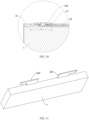
- FIG. 9 is a schematic diagram of an internal structure of a battery cell according to some embodiments of this application.
- FIG. 10 is a schematic structural diagram at an electrode terminal 102 in FIG. 9 .
- the housing 101 includes a first wall, the electrode terminal 102 is disposed on the first wall, and the end face 11 faces the first wall.
- the electrode terminal 102 is located at one end of the first wall, and the positive electrode tab 201 and the negative electrode tab 202 extend in directions leaving each other.
- the lead-out positions of the positive electrode tab 201 and the negative electrode tab 202 on the end face 11 can be gathered towards the center, reducing interference of the positive electrode tab 201 and the negative electrode tab 202 with components on both sides. This furthermore allows for a greater spacing between connection regions on the positive electrode tab 201 and the negative electrode tab 202, thereby improving the safety of the battery cell.
- the first wall is also provided with an insulating plate 3 on a side facing the electrode assembly 103, and the insulating plate 3 is configured to insulate the first wall from the electrode assembly 103.
- the insulating plate 3 may be made of a material such as plastic or rubber.
- the insulating plate 3 is provided with a protruding block 31 extending towards the end face, the protruding block 31 abuts against the end face, and the protruding block 31 can reduce the shaking of the electrode assembly 103.
- a distance between the second connecting portion 22 and the insulating plate is L, where L ⁇ 0.5 mm. Limiting the relative distance between the protruding block 31 and the second connecting portion 22 can significantly reduce the problem of short circuit caused by mutual squeezing and abutting between the second connecting portion 22 and the protruding block 31.
- the distance between the second connecting portion 22 and the insulating plate is L, where 0.5 mm ⁇ L ⁇ 70 mm.
- the distance L between the second connecting portion 22 and the insulating plate may be 1 mm, 3 mm, 5 mm, 10 mm, 20 mm, 30 mm, 40 mm, 50 mm, or 60 mm.
- at least three protruding blocks 31 are provided, respectively corresponding to two sides and the middle of the end face.
- the distance between the second connecting portion 22 and the insulating plate may be a distance between the second connecting portion 22 of the positive electrode tab and one of the protruding blocks 31, and the distance between the second connecting portion 22 and the insulating plate may also be a distance between the second connecting portion 22 of the negative electrode tab and one of the protruding blocks 31.
- FIG. 11 is a schematic structural diagram of an electrode assembly 103 according to yet some embodiments of this application.
- the tab 2 includes multiple layers of sub tabs, and in adjacent two of the layers of sub tabs, a projection of the sub tab close to the electrode terminal 102 on the end face covers a projection of the sub tab far from the electrode terminal 102.
- the sizes of the sub tabs are gradually increased in the direction towards the electrode terminal 102, such that the sub tab on a side close to the electrode terminal 102 can completely cover the sub tab on a side away from the electrode terminal 102.
- the tab 2 is formed by stacking multiple layers of sub tabs.
- the sub tab of the inner layer is bent at a small angle, while the sub tab of the outer layer is bent at a large angle. Therefore, with the same size set, the edges of the bent tab 2 are uneven and difficult to standardize. As a result, after placed in the housing 101, the electrode assembly 103 is likely to interfere with it.
- the area of the sub tabs increases arithmetically or geometrically.
- the area of the first connecting portion 21 on the sub tabs increases arithmetically or geometrically.
- the first connecting portion 21 is bent relative to the second connecting portion 22. Bending the first connecting portion 21 and the second connecting portion 22 can reduce the space occupied by the tabs 2, thereby increasing the energy density of the battery cell.
- a battery is further provided, including the foregoing battery cell.
- an electric apparatus including the foregoing battery cell and configured to provide electrical energy.
- a battery cell including the housing 101, the electrode terminal 102, and the electrode assembly 103.
- the electrode terminal 102 is disposed on the housing 101, and the electrode assembly 103 is accommodated in the housing 101.
- the electrode assembly 103 includes a main body portion 1 and a tab 2, and the tab 2 extends out of an end face 11 of the main body portion 1.
- the tab 2 includes a first connecting portion 21 and a second connecting portion 22, where the first connecting portion 21 is bent relative to the second connecting portion 22.
- the first connecting portion 21 is configured to be connected to the electrode terminal 102, and the second connecting portion 22 is configured to be connected to the main body portion 1.
- the second connecting portion 22 is configured to be connected to the main body portion 1.
- at least part of the first connecting portion 21 exceeds the second connecting portion 22.
- the first connecting portion 21 is connected to the electrode terminal 102 to form a connection region, and along a length direction of the end face, the connection region exceeds the second connecting portion 22. Along the length direction of the end face, a size of the first connecting portion 21 is greater than a size of the second connecting portion 22.
- the tab 2 is L-shaped or T-shaped.
- the tab 2 includes a positive electrode tab 201 and a negative electrode tab 202, the positive electrode tab 201 and the negative electrode tab 202 are both located on the end face, and the positive electrode tab 201 and the negative electrode tab 202 each include a first connecting portion 21 and a second connecting portion 22.
- the housing 101 includes a first wall, the electrode terminal 102 is disposed on the first wall, and the end face faces the first wall.
- the electrode terminal 102 is located at one end of the first wall, and the positive electrode tab and the negative electrode tab extend in directions leaving each other.
- the first wall is also provided with an insulating plate 3 on a side facing the electrode assembly 103, and the insulating plate 3 is configured to insulate the first wall from the electrode assembly 103.
- the insulating plate 3 is provided with a protruding block 31 extending towards the end face, the protruding block 31 abuts against the end face, and along the length direction of the end face, a distance between the second connecting portion 22 and the insulating plate is L, where L ⁇ 0.5 mm.
- the tab 2 includes multiple layers of sub tabs, and in adjacent two of the layers of sub tabs, a projection of the sub tab close to the electrode terminal 102 on the end face covers a projection of the sub tab far from the electrode terminal 102.
- the connectable range of the first connecting portion 21 in the length direction of the end face can be expanded, facilitating direct connection of the first connecting portion 21 with the electrode terminal 102. This optimizes the internal structure of the battery cell, increases the available space for the electrode assembly 103, and increases the energy density of the battery cell.
Landscapes
- Chemical & Material Sciences (AREA)
- Chemical Kinetics & Catalysis (AREA)
- Electrochemistry (AREA)
- General Chemical & Material Sciences (AREA)
- Engineering & Computer Science (AREA)
- Manufacturing & Machinery (AREA)
- Connection Of Batteries Or Terminals (AREA)
Abstract
Description
- This application claims priority to
Chinese Patent Application No. 202210823644.5, filed on July 14, 2022 - This application pertains to the field of battery technologies, and in particular, to a battery cell, a battery, and an electric apparatus.
- With the increasing depletion of natural resources and the worsening damage to the environment, there is a growing interest across various fields in apparatus that can store energy and effectively utilize stored energy. The battery cells can be combined into a system for using new renewable energy.
- How the energy density of battery cells is increased is an important research direction in battery technologies.
- Embodiments of this application provide a battery cell, a battery, and an electric apparatus, which implement direct connection between a tab and an electrode terminal, thereby increasing the energy density of the battery.
- According to a first aspect, an embodiment of this application provides a battery cell, including a housing, an electrode terminal, and an electrode assembly. The electrode terminal is disposed on the housing, and the electrode assembly is accommodated in the housing. The electrode assembly includes a main body portion and a tab, the tab extends out of an end face of the main body portion, the tab includes a first connecting portion and a second connecting portion, the first connecting portion is configured to be connected to the electrode terminal, and the second connecting portion is configured to be connected to the main body portion. Along a length direction of the end face, at least part of the first connecting portion exceeds the second connecting portion.
- With the use of the foregoing structure, as the first connecting portion exceeds the second connecting portion in the length direction of the end face, the connectable range of the first connecting portion in the length direction of the end face can be expanded, facilitating direct connection of the first connecting portion with the electrode terminal. This optimizes the internal structure of the battery cell, increases the available space for the electrode assembly, and increases the energy density of the battery cell.
- In some optional embodiments of this application, the first connecting portion is connected to the electrode terminal to form a connection region, and along a length direction of the end face, at least part of the connection region exceeds the second connecting portion.
- With the use of the foregoing structure, as the connection region exceeds the second connecting portion along the length direction of the end face, a connection position between the first connecting portion and the electrode terminal can be on an exceeding portion of the first connecting portion. Even if a position where the tab is led out is not aligned with the electrode terminal, the tab can still be connected to the electrode terminal via the part of the first connecting portion exceeding the second connecting portion.
- In some optional embodiments of this application, along the length direction of the end face, a size of the first connecting portion is greater than a size of the second connecting portion.
- With the use of the foregoing structure, as the size of the first connecting portion is greater than the size of the second connecting portion in the length direction of the end face, the first connecting portion can obtain a larger area, facilitating connection to the electrode terminal.
- In some optional embodiments of this application, a notch is provided at a joint between the second connecting portion and the main body portion.
- With the use of the foregoing structure, the arrangement of the notch can shrink a size of a connection position of the second connecting portion to the main body portion, increasing a distance between the second connecting portion and another component in the battery cell (for example, an insulating plate between the electrode assembly and the first wall), thereby avoiding interference between the second connecting portion and other components.
- In some optional embodiments of this application, the tab is L-shaped or T-shaped.
- With the use of the foregoing structure, as the tab is arranged to be L-shaped or T-shaped, the size of the first connecting portion in the length direction of the end face can be significantly increased, facilitating connection of the tab with the electrode terminal. This also significantly reduces the size of the second connecting portion in the length direction of the end face, preventing the second connecting portion from contacting the protruding block.
- In some optional embodiments of this application, the tab includes a positive electrode tab and a negative electrode tab, the positive electrode tab and the negative electrode tab are both located on the end face, the positive electrode tab and the negative electrode tab each include a first connecting portion and a second connecting portion, and the first connecting portion of the positive electrode tab and the first connecting portion of the negative electrode tab extend in opposite directions.
- With the use of the foregoing structure, as the first connecting portions of the positive electrode tab and the negative electrode tab extend in opposite directions, the tab can meet the setting requirements of different types of electrode terminals. For example, when the electrode terminal is located between the second connecting portions of the positive electrode tab and the negative electrode tab, the two first connecting portions extend in directions approaching each other. When the electrode terminal is located on both sides of the second connecting portions of the positive electrode tab and the negative electrode tab, the two first connecting portions extend in directions back away from each other.
- In some optional embodiments of this application, the housing includes a first wall, the electrode terminal is disposed on the first wall, and the end face faces the first wall.
- In some optional embodiments of this application, the electrode terminal is located at one end of the first wall, and the positive electrode tab and the negative electrode tab extend in directions leaving each other.
- With the use of the foregoing structure, as the electrode terminal is disposed at the end of the first wall and the positive electrode tab and the negative electrode tab extend in directions leaving each other, the lead-out positions of the positive electrode tab and the negative electrode tab on the end face can be gathered towards the center, reducing interference of the positive electrode tab and the negative electrode tab with components on both sides. This furthermore allows for a greater spacing between connection regions on the positive electrode tab and the negative electrode tab, thereby improving the safety of the battery cell.
- In some optional embodiments of this application, the first wall is also provided with an insulating plate on a side facing the electrode assembly, and the insulating plate is configured to insulate the first wall from the electrode assembly.
- In some optional embodiments of this application, the insulating plate is provided with a protruding block extending towards the end face, the protruding block abuts against the end face, and along the length direction of the end face, a distance between the second connecting portion and the insulating plate is L, where L ≥ 0.5 mm.
- With the use of the foregoing structure, limiting the relative distance between the protruding block and the second connecting portion can significantly reduce the problem of short circuit caused by mutual squeezing and abutting between the second connecting portion and the protruding block.
- In some optional embodiments of this application, the tab includes multiple layers of sub tabs, and in adjacent two of the layers of sub tabs, a projection of the sub tab close to the electrode terminal on the end face covers a projection of the sub tab far from the electrode terminal.
- With the use of the foregoing structure, gradually increasing the size of the sub tabs in the direction towards the electrode terminal allows the sub tab on a side close to the electrode terminal to completely cover the sub tab on a side away from the electrode terminal, improving the current carrying capacity of the tab and reducing interference of the tab with the protruding block.
- In some optional embodiments of this application, the first connecting portion is bent relative to the second connecting portion.
- With the use of the foregoing structure, bending the first connecting portion and the second connecting portion can reduce the space occupied by the tabs, thereby increasing the energy density of the battery cell.
- According to a second aspect, an embodiment of this application provides a battery, including the foregoing battery cell.
- According to a third aspect, an embodiment of this application provides an electric apparatus, which includes the foregoing battery cell and is configured to provide electrical energy.
- Compared with the related art, in the battery cell, the battery, and the electric apparatus of the embodiments of this application, as the first connecting portion exceeds the second connecting portion in the length direction of the end face, the connectable range of the first connecting portion in the length direction of the end face can be expanded, facilitating direct connection of the first connecting portion with the electrode terminal. This optimizes the internal structure of the battery cell, increases the available space for the electrode assembly, and increases the energy density of the battery cell.
- To describe the technical solutions in the embodiments of this application more clearly, the following briefly describes the accompanying drawings required for describing the embodiments of this application. Apparently, the accompanying drawings in the following description show merely some embodiments of this application, and a person of ordinary skills in the art may still derive other drawings from the accompanying drawings without creative efforts.
-
FIG. 1 is a schematic structural diagram of a vehicle according to some embodiments of this application. -
FIG. 2 is a schematic structural diagram of a battery according to some embodiments of this application. -
FIG. 3 is a schematic structural diagram of a battery cell according to some embodiments of this application. -
FIG. 4 is a schematic structural diagram of an electrode assembly according to some embodiments of this application. -
FIG. 5 is a schematic structural diagram of an electrode assembly according to some other embodiments of this application. -
FIG. 6 is a schematic structural diagram of an electrode assembly according to still some other embodiments of this application. -
FIG. 7 is a schematic structural front view according to the embodiments inFIG. 6 . -
FIG. 8 is a schematic structural top view according to the embodiments inFIG. 6 . -
FIG. 9 is a schematic diagram of an internal structure of a battery cell according to some embodiments of this application. -
FIG. 10 is a schematic structural diagram at an electrode terminal inFIG. 9 . -
FIG. 11 is a schematic structural diagram of an electrode assembly according to yet some embodiments of this application. - In the accompanying drawings:
1000. vehicle; 100. battery; 200. controller; 300. motor; 110. box; 111. first box portion; 112. second box portion; 101. housing; 1011. end cover; 1012. shell; 102. electrode terminal; 103. electrode assembly; 1. main body portion; 11. end face; 2. tab; 201. positive electrode tab; 202. negative electrode tab; 21. first connecting portion; 211. connection region; 212. first edge; 213. second edge; 22. second connecting portion; 221. first end; 222. second end; 23. notch; 3. insulating plate; and 31. protruding block. - The following describes in detail embodiments of technical solutions of this application with reference to the accompanying drawings. The following embodiments are merely intended for a clearer description of the technical solutions of this application and therefore are used as just examples which do not constitute any limitations on the protection scope of this application.
- Unless otherwise defined, all technical and scientific terms used herein shall have the same meanings as commonly understood by persons skilled in the art to which this application relates. The terms used herein are intended to merely describe the specific embodiments rather than to limit this application. The terms "include", "comprise", and "have" and any other variations thereof in the specification, claims and brief description of drawings of this application are intended to cover non-exclusive inclusions.
- In the descriptions of the embodiments of this application, the technical terms "first", "second", and the like are merely intended to distinguish between different objects, and shall not be understood as any indication or implication of relative importance or any implicit indication of the number, specific sequence, or primarysecondary relationship of the technical features indicated.
- Reference to "embodiment" in the specification means that specific features, structures, or characteristics described with reference to the embodiment may be included in at least one embodiment of this application. The word "embodiment" appearing in various places in this specification does not necessarily refer to the same embodiment or an independent or alternative embodiment that is exclusive of other embodiments. It is explicitly or implicitly understood by persons skilled in the art that the embodiments described herein may be combined with other embodiments.
- In the description of the embodiments of this application, the term "and/or" is only an associative relationship for describing associated objects, indicating that three relationships may be present. For example, A and/or B may indicate the following three cases: presence of only A, presence of both A and B, and presence of only B. In addition, the character "/" in this specification generally indicates an "or" relationship between contextually associated objects.
- In the descriptions of the embodiments of this application, the term "multiple" means more than two (inclusive). Similarly, "multiple groups" means more than two (inclusive) groups, and "multiple pieces" means more than two (inclusive) pieces.
- In the description of the embodiments of this application, the orientations or positional relationships indicated by the technical terms "center", "longitudinal" "transverse", "length", "width", "thickness", "upper", "lower", "front", "rear", "left", "right", "vertical", "horizontal", "top", "bottom", "inside", "outside", "clockwise", "counterclockwise", "axial", "radial", "circumferential", and the like are based on the orientations or positional relationships as shown in the accompanying drawings. These terms are merely for ease and brevity of the description of the embodiments of this application rather than indicating or implying that the means or components mentioned must have specific orientations, or must be constructed or manipulated according to specific orientations, and therefore shall not be construed as any limitations on embodiments of this application.
- In the description of the embodiments of this application, unless otherwise specified and defined explicitly, the technical terms "mounting", "connection", "join", and "fastening" should be understood in their general senses. For example, they may refer to a fixed connection, a detachable connection, or an integral connection, may refer to a mechanical connection or an electrical connection, and may refer to a direct connection, an indirect connection through an intermediary, an internal communication between two elements, or an interaction between two elements. Persons of ordinary skills in the art can understand specific meanings of these terms in this application as appropriate to specific situations.
- The development of battery technology requires consideration of multiple design factors, such as cycle life and battery safety. The energy density of a battery cell has become a constraint on the further promotion of batteries.
- A battery cell typically includes a housing and an electrode assembly, where the electrode assembly is a crucial part for completing the electrochemical process of the battery. It usually consists of electrode plates and a separator, with the electrode plates including a positive electrode plate and a negative electrode plate. The positive electrode plate and negative electrode plate each include a current collector and an active material layer applied to it. The electrochemical process mainly relies on the movement of metal ions, such as lithium ions, between the positive electrode plate and negative electrode plate within the active material layer. Therefore, the energy density of a battery cell is closely related to the volume ratio of the electrode assembly.
- The inventors noted that in a battery cell, to lead out the electrical energy from the electrode assembly, an electrode terminal needs to be disposed on the housing. A side of the electrode terminal near the inside of the housing needs to be connected to the electrode assembly. For the convenience of leading out the electrical energy on the electrode assembly, a tab is arranged to be connected with the electrode terminal. However, due to limitation of the production process, it is difficult to completely align the positions of the tab and the electrode terminal. To improve the connection efficiency between the electrode terminal and the tab, a connecting component is usually used to connect the tab with the electrode terminal. Clearly, arranging the connecting component additionally occupies the space in the housing, reducing the space available for the electrode assembly and thus decreasing the energy density of the battery cell.
- To alleviate the problem of reduced energy density in the battery cell, the inventors found that adjusting the structure of the tab can efficiently connect the tab to the electrode terminal without a connecting component. This reduces the internal structure of the housing and increases the space available for the electrode assembly, thereby increasing the energy density of the battery.
- Based on the foregoing consideration, the inventors of this application have conducted in-depth research and designed a battery cell, a battery, and an electric apparatus.
- An embodiment of this application provides an electric apparatus that uses a battery as a power source. The electric apparatus may be but is not limited to a mobile phone, a tablet, a notebook computer, an electric toy, an electric tool, an electric bicycle, an electric car, a ship, or a spacecraft. The electric toy may include a fixed or mobile electric toy, for example, a game console, an electric toy car, an electric toy ship, and an electric toy airplane. The spacecraft may include an airplane, a rocket, a space shuttle, a spaceship, and the like.
- For ease of description, the electric apparatus of an embodiment of this application being a
vehicle 1000 is used as an example for description of the following embodiments. - As shown in
FIG. 1, FIG. 1 is a schematic structural diagram of avehicle 1000 according to some embodiments of this application. Thevehicle 1000 may be a fossil fuel vehicle, a natural-gas vehicle, or a new energy vehicle, where the new energy vehicle may be a battery electric vehicle, a hybrid electric vehicle, a range-extended vehicle, or the like. Thevehicle 1000 is provided with abattery 100 inside, where thebattery 100 may be disposed at the bottom, front or rear of thevehicle 1000. Thebattery 100 may be configured to supply power to thevehicle 1000. For example, thebattery 100 may be used as an operational power source for thevehicle 1000. Thevehicle 1000 may further include acontroller 200 and amotor 300, where thecontroller 200 is configured to control thebattery 100 to supply power to themotor 300, for example, to satisfy power needs of start, navigation, and driving of thevehicle 1000. - In some embodiments of this application, the
battery 100 can be used as not only the operational power source for thevehicle 1000 but also a driving power source for thevehicle 1000, replacing or partially replacing fossil fuel or natural gas to provide driving traction for thevehicle 1000. - The battery mentioned in the embodiments of this application is a single physical module that includes one or more battery cells for providing higher voltage and capacity. For example, the battery mentioned in this application may include a battery module, a battery pack, or the like.
- As shown in
FIG. 2, FIG. 2 is a schematic structural diagram of abattery 100 according to some embodiments of this application. In some embodiments of this application, thebattery 100 includes abox 110. Thebox 110 may include afirst box portion 111 and asecond box portion 112 connected together. After connected in parallel, in series, or in parallel and series, multiple battery cells are placed in the space formed by thefirst box portion 111 and thesecond box portion 112 through connection. The shapes of thefirst box portion 111 and thesecond box portion 112 can be determined according to the shape formed by combined multiple battery cells. The battery cell may be cylindrical, flat, rectangular, or of other shapes. This embodiment of this application does not limit this. According to the packaging methods, the battery cells include but are not limited to cylindrical battery cells, prismatic battery cells, and pouch battery cells. This embodiment of this application does not limit this. In addition, thebattery 100 may further include other structures, such as a busbar component configured to achieve electrical connection between multiple battery cells, which is detailed herein. -
FIG. 3 is a schematic structural diagram of a battery cell according to some embodiments of this application;FIG. 4 is a schematic structural diagram of anelectrode assembly 103 according to some embodiments of this application. - As shown in
FIGs. 3 and 4 , some embodiments of this application provide abattery cell 10, including ahousing 101, anelectrode terminal 102, and anelectrode assembly 103. Theelectrode terminal 102 is disposed on thehousing 101, and theelectrode assembly 103 is accommodated in thehousing 101. Theelectrode assembly 103 includes amain body portion 1 and atab 2, thetab 2 extends out of anend face 11 of themain body portion 1, thetab 2 includes a first connectingportion 21 and a second connectingportion 22, the first connectingportion 21 is configured to be connected to theelectrode terminal 102, and the second connectingportion 22 is configured to be connected to themain body portion 1. Along a length direction (an x-axis direction inFIG. 4 ) of the end face, at least part of the first connectingportion 21 exceeds the second connectingportion 22. - The
housing 101 is a component used for forming the internal environment of the battery cell. The formed internal environment can be used for accommodating theelectrode assembly 103, electrolyte (not shown in the figure), and other components. Thehousing 101 may have various structural forms, such as a cuboid or a cylinder. For example, the shape of thehousing 101 can be determined according to the specific shape of theelectrode assembly 103. Thehousing 101 may be made of various materials, such as copper, iron, aluminum, stainless steel, aluminum alloy, and plastic. This is not particularly limited in the embodiments of this application. - The
electrode assembly 103 is an assembly used for electrochemical reaction in the battery cell. For example, theelectrode assembly 103 is mainly formed by winding or stacking a positive electrode plate and a negative electrode plate, and a separator is usually sandwiched between the positive electrode plate and the negative electrode plate. Part of the positive electrode plate with an active substance, part of the negative electrode plate with the active substance, and the separator constitute themain body portion 1 of theelectrode assembly 103. Parts of the positive electrode plate and negative electrode plate without the active substance each form atab 2. During charge and discharge of the battery, a positive electrode active substance and a negative electrode active substance react with an electrolyte, and thetabs 2 are connected to theelectrode terminals 102 to form a current loop. - The
electrode terminal 102 is used to be electrically connected with thetab 2, such that the electrical energy is led out of or introduced into the battery cell. For example, theelectrode terminal 102 has one end arranged in thehousing 101 to be connected with thetab 2, and the other end arranged outside thehousing 101. - As the first connecting
portion 21 exceeds the second connectingportion 22 in the length direction of the end face, the connectable range of the first connectingportion 21 in the length direction of the end face can be expanded, facilitating direct connection of the first connectingportion 21 with theelectrode terminal 102. This optimizes the internal structure of the battery cell, increases the available space for theelectrode assembly 103, and increases the energy density of the battery cell. - Optionally, the
housing 101 may include ashell 1012 and anend cover 1011. Theshell 1012 is a hollow structure with an opening on one side, and theend cover 1011 covers the opening of theshell 1012 to enable a sealed connection, so as to create a sealed space for accommodating theelectrode assembly 103 and an electrolyte. Theelectrode terminal 102 is arranged on theend cover 1011. Theelectrode terminal 102 may include apositive electrode terminal 102 and anegative electrode terminal 102. Thepositive electrode terminal 102 and thenegative electrode terminal 102 are configured to be connected to a positive electrode tab and a negative electrode tab on theelectrode assembly 103, so as to output the electrical energy generated by theelectrode assembly 103. - Optionally, the
housing 101 may further have other structures. For example, thehousing 101 includes ashell 1012 and two end covers 1011. Theshell 1012 is a hollow structure with openings on two opposite sides. Oneend cover 1011 corresponds to and covers one opening of theshell 1012, enabling a sealed connection, so as to create a sealed space for accommodating theelectrode assembly 103 and the electrolyte. In this structure, thepositive electrode terminal 102 and thenegative electrode terminal 102 may be mounted on thesame end cover 1011 or on different end covers 1011. -
FIG. 5 is a schematic structural diagram of anelectrode assembly 103 according to some other embodiments of this application. Referring toFIGs. 4 and5 , optionally, in the length direction of the end face (the x-axis direction inFIGs. 4 and5 ), the second connectingportion 22 includes afirst end 221 and asecond end 222 being opposite each other, and the first connectingportion 21 at least extends to exceed one of thefirst end 221 and thesecond end 222. -
FIG. 6 is a schematic structural diagram of anelectrode assembly 103 according to still some other embodiments of this application.FIG. 7 is a schematic structural front view according to the embodiments inFIG. 6 .FIG. 8 is a schematic structural top view according to the embodiments inFIG. 6 . ReferencingFIGs. 6 to 8 , optionally, in the length direction of the end face (the x-axis direction inFIG. 8 ), the first connectingportion 21 includes afirst edge 212 and asecond edge 213, where the first edge and thesecond edge 213 can be arranged at an included angle with the width direction of the end face (the y-axis direction inFIGs. 6 and8 ). Optionally, thefirst edge 212 and thesecond edge 213 may be arranged as straight lines or curves. - Referencing
FIGs. 6 to 8 , optionally, thefirst end 221 and thesecond end 222 are arranged at an included angle to the direction perpendicular to the end face (the z-axis direction inFIG. 7 ). - Optionally, the extension direction of the first connecting
portion 21 may be perpendicular to the width direction of the end face, and the extension direction of the second connectingportion 22 may be parallel to the direction perpendicular to the end face, and in the length direction of the end face, the first connectingportion 21 and the second connectingportion 22 staggered. Specifically, along the length direction of the end face, a size of the first connectingportion 21 may be less than a size of the second connectingportion 22. - As shown in
FIGs. 4 to 6 , in some optional embodiments of this application, the first connectingportion 21 is connected to theelectrode terminal 102 to form aconnection region 211, and in the length direction of the end face (the x-axis direction inFIGs. 4 to 6 ), at least part of the connection region exceeds the second connectingportion 22. - The
connection region 211 is the connection region between the first connectingportion 21 and theelectrode terminal 102 after they are connected. For example, if the first connectingportion 21 is welded to theelectrode terminal 102, theconnection region 211 is a welded region formed through welding. If the first connectingportion 21 is glued to theelectrode terminal 102, theconnection region 211 is a glued region formed through gluing. - As the
connection region 211 exceeds the second connectingportion 22 along the length direction of the end face, a connection position between the first connectingportion 21 and theelectrode terminal 102 can be on an exceeding portion of the first connectingportion 21. Even if a position where thetab 2 is led out is not aligned with theelectrode terminal 102, thetab 2 can still be connected to theelectrode terminal 102 via the part of the first connectingportion 21 exceeding the second connectingportion 22. - Optionally, in the length direction of the end face (the x-axis direction in
FIGs. 4 to 6 ), the second connectingportion 22 includes afirst end 221 and asecond end 222 being opposite each other. Theconnection region 211 may be partially located outside thefirst end 221 and thesecond end 222, or may be entirely located outside thefirst end 221 and thesecond end 222. - As shown in
FIG. 4 , in some optional embodiments of this application, in the length direction of the end face (the x-axis direction inFIG. 4 ), the size of the first connectingportion 21 is greater than the size of the second connectingportion 22. As the size of the first connectingportion 21 is greater than the size of the second connectingportion 22 in the length direction of the end face, the first connectingportion 21 can obtain a larger area, facilitating connection to theelectrode terminal 102. - As shown in
FIGs. 4 to 6 , in some optional embodiments of this application, anotch 23 is provided at the joint between the second connectingportion 22 and themain body portion 1. The arrangement of thenotch 23 can shrink a size of a connection position of the second connectingportion 22 to themain body portion 1, increasing a distance between the second connectingportion 22 and another component in the battery cell (for example, an insulating plate between the electrode assembly and the first wall), thereby avoiding interference between the second connectingportion 22 and other components. - As shown in
FIG. 4 , in some optional embodiments of this application, thetab 2 is L-shaped or T-shaped. As thetab 2 is arranged to be L-shaped or T-shaped, the size of the first connectingportion 21 in the length direction (the x-axis direction inFIG. 4 ) of the end face can be significantly increased, facilitating connection of thetab 2 with theelectrode terminal 102. This also significantly reduces the size of the second connectingportion 22 in the length direction of the end face, preventing the second connectingportion 22 from contacting the protrudingblock 31. - Optionally, when the
tab 2 is L-shaped, the horizontal section of the L-shape is the first connectingportion 21, and the vertical section of the L-shape is the second connectingportion 22. Optionally, when thetab 2 is T-shaped, one of the two edges connected to the center of the other edge is the first connectingportion 21, and the other is the second connectingportion 22. - As shown in
FIGs. 3 to 6 , in some optional embodiments of this application, thetab 2 includes apositive electrode tab 201 and anegative electrode tab 202, thepositive electrode tab 201 and thenegative electrode tab 202 are both located on the end face, thepositive electrode tab 201 and thenegative electrode tab 202 each include a first connectingportion 21 and a second connectingportion 22, and the first connectingportion 21 of thepositive electrode tab 201 and the first connectingportion 21 of thenegative electrode tab 202 extend in opposite directions. - The first connecting
portion 21 of thepositive electrode tab 201 and the first connectingportion 21 of thenegative electrode tab 202 extend in opposite directions, meaning that the first connectingportion 21 of thepositive electrode tab 201 and the first connectingportion 21 of thenegative electrode tab 202 may extend in directions approaching each other, or the first connectingportion 21 of thepositive electrode tab 201 and the first connectingportion 21 of thenegative electrode tab 202 may extend in directions back away from each other. - As the first connecting portions of the positive electrode tab and the negative electrode tab extend in opposite directions, the
tab 2 can meet the setting requirements of different types ofelectrode terminals 102. For example, when theelectrode terminal 102 is located between the second connectingportions 22 of thepositive electrode tab 201 and thenegative electrode tab 202, the two first connectingportions 21 extend in directions approaching each other. When theelectrode terminal 102 is located on both sides of the second connectingportions 22 of thepositive electrode tab 201 and thenegative electrode tab 202, the two first connectingportions 21 extend in directions back away from each other. -
FIG. 9 is a schematic diagram of an internal structure of a battery cell according to some embodiments of this application.FIG. 10 is a schematic structural diagram at anelectrode terminal 102 inFIG. 9 . - As shown in
FIGs. 3 ,9 , and10 , in some optional embodiments of this application, thehousing 101 includes a first wall, theelectrode terminal 102 is disposed on the first wall, and theend face 11 faces the first wall. - As shown in
FIGs. 3 ,9 , and10 , in some optional embodiments of this application, theelectrode terminal 102 is located at one end of the first wall, and thepositive electrode tab 201 and thenegative electrode tab 202 extend in directions leaving each other. As theelectrode terminal 102 is disposed at the end of the first wall and thepositive electrode tab 201 and thenegative electrode tab 202 extend in directions leaving each other, the lead-out positions of thepositive electrode tab 201 and thenegative electrode tab 202 on theend face 11 can be gathered towards the center, reducing interference of thepositive electrode tab 201 and thenegative electrode tab 202 with components on both sides. This furthermore allows for a greater spacing between connection regions on thepositive electrode tab 201 and thenegative electrode tab 202, thereby improving the safety of the battery cell. - As shown in
FIGs. 3 ,9 , and10 , in some optional embodiments of this application, the first wall is also provided with an insulatingplate 3 on a side facing theelectrode assembly 103, and the insulatingplate 3 is configured to insulate the first wall from theelectrode assembly 103. The insulatingplate 3 may be made of a material such as plastic or rubber. - As shown in
FIGs. 3 ,9 , and10 , in some optional embodiments of this application, the insulatingplate 3 is provided with a protrudingblock 31 extending towards the end face, the protrudingblock 31 abuts against the end face, and the protrudingblock 31 can reduce the shaking of theelectrode assembly 103. - In some optional embodiments of this application, along the length direction of the end face, a distance between the second connecting
portion 22 and the insulating plate is L, where L ≥ 0.5 mm. Limiting the relative distance between the protrudingblock 31 and the second connectingportion 22 can significantly reduce the problem of short circuit caused by mutual squeezing and abutting between the second connectingportion 22 and the protrudingblock 31. - Preferably, the distance between the second connecting
portion 22 and the insulating plate is L, where 0.5 mm ≤ L ≤ 70 mm. Preferably, the distance L between the second connectingportion 22 and the insulating plate may be 1 mm, 3 mm, 5 mm, 10 mm, 20 mm, 30 mm, 40 mm, 50 mm, or 60 mm. Preferably, at least three protrudingblocks 31 are provided, respectively corresponding to two sides and the middle of the end face. In the length direction of theend face 11, the distance between the second connectingportion 22 and the insulating plate may be a distance between the second connectingportion 22 of the positive electrode tab and one of the protruding blocks 31, and the distance between the second connectingportion 22 and the insulating plate may also be a distance between the second connectingportion 22 of the negative electrode tab and one of the protruding blocks 31. -
FIG. 11 is a schematic structural diagram of anelectrode assembly 103 according to yet some embodiments of this application. As shown inFIG. 11 , in some optional embodiments of this application, thetab 2 includes multiple layers of sub tabs, and in adjacent two of the layers of sub tabs, a projection of the sub tab close to theelectrode terminal 102 on the end face covers a projection of the sub tab far from theelectrode terminal 102. The sizes of the sub tabs are gradually increased in the direction towards theelectrode terminal 102, such that the sub tab on a side close to theelectrode terminal 102 can completely cover the sub tab on a side away from theelectrode terminal 102. Thetab 2 is formed by stacking multiple layers of sub tabs. During bending, the sub tab of the inner layer is bent at a small angle, while the sub tab of the outer layer is bent at a large angle. Therefore, with the same size set, the edges of thebent tab 2 are uneven and difficult to standardize. As a result, after placed in thehousing 101, theelectrode assembly 103 is likely to interfere with it. - Preferably, in the direction towards the
electrode terminal 102, the area of the sub tabs increases arithmetically or geometrically. - Preferably, in the direction towards the
electrode terminal 102, the area of the first connectingportion 21 on the sub tabs increases arithmetically or geometrically. - In some optional embodiments of this application, the first connecting
portion 21 is bent relative to the second connectingportion 22. Bending the first connectingportion 21 and the second connectingportion 22 can reduce the space occupied by thetabs 2, thereby increasing the energy density of the battery cell. - In some optional embodiments of this application, a battery is further provided, including the foregoing battery cell.
- In some optional embodiments of this application, an electric apparatus is also provided, including the foregoing battery cell and configured to provide electrical energy.
- In some optional embodiments of this application, a battery cell is also provided, including the
housing 101, theelectrode terminal 102, and theelectrode assembly 103. Theelectrode terminal 102 is disposed on thehousing 101, and theelectrode assembly 103 is accommodated in thehousing 101. Theelectrode assembly 103 includes amain body portion 1 and atab 2, and thetab 2 extends out of anend face 11 of themain body portion 1. Thetab 2 includes a first connectingportion 21 and a second connectingportion 22, where the first connectingportion 21 is bent relative to the second connectingportion 22. The first connectingportion 21 is configured to be connected to theelectrode terminal 102, and the second connectingportion 22 is configured to be connected to themain body portion 1. Along a length direction of theend face 11, at least part of the first connectingportion 21 exceeds the second connectingportion 22. The first connectingportion 21 is connected to theelectrode terminal 102 to form a connection region, and along a length direction of the end face, the connection region exceeds the second connectingportion 22. Along the length direction of the end face, a size of the first connectingportion 21 is greater than a size of the second connectingportion 22. Thetab 2 is L-shaped or T-shaped. Thetab 2 includes apositive electrode tab 201 and anegative electrode tab 202, thepositive electrode tab 201 and thenegative electrode tab 202 are both located on the end face, and thepositive electrode tab 201 and thenegative electrode tab 202 each include a first connectingportion 21 and a second connectingportion 22. Thehousing 101 includes a first wall, theelectrode terminal 102 is disposed on the first wall, and the end face faces the first wall. Theelectrode terminal 102 is located at one end of the first wall, and the positive electrode tab and the negative electrode tab extend in directions leaving each other. The first wall is also provided with an insulatingplate 3 on a side facing theelectrode assembly 103, and the insulatingplate 3 is configured to insulate the first wall from theelectrode assembly 103. The insulatingplate 3 is provided with a protrudingblock 31 extending towards the end face, the protrudingblock 31 abuts against the end face, and along the length direction of the end face, a distance between the second connectingportion 22 and the insulating plate is L, where L ≥ 0.5 mm. Thetab 2 includes multiple layers of sub tabs, and in adjacent two of the layers of sub tabs, a projection of the sub tab close to theelectrode terminal 102 on the end face covers a projection of the sub tab far from theelectrode terminal 102. - Compared with the related art, in the battery cell, the battery, and the electric apparatus of the embodiments of this application, as the first connecting
portion 21 exceeds the second connectingportion 22 in the length direction of the end face, the connectable range of the first connectingportion 21 in the length direction of the end face can be expanded, facilitating direct connection of the first connectingportion 21 with theelectrode terminal 102. This optimizes the internal structure of the battery cell, increases the available space for theelectrode assembly 103, and increases the energy density of the battery cell. - In conclusion, it should be noted that the foregoing embodiments are for description of the technical solutions of this application only rather than for limiting this application. Although this application has been described in detail with reference to the foregoing embodiments, persons of ordinary skill in the art should appreciate that they can still make modifications to the technical solutions described in the embodiments or make equivalent replacements to some or all technical features thereof without departing from the scope of the technical solutions of the embodiments of this application. All such modifications and equivalent replacements shall fall within the scope of claims and specification of this application. In particular, as long as there is no structural conflict, the various technical features mentioned in the embodiments can be combined in any manner. This application is not limited to the specific embodiments disclosed in this specification but includes all technical solutions falling within the scope of the claims.
Claims (14)
- A battery cell, comprising:a housing;an electrode terminal disposed on the housing; andan electrode assembly accommodated in the housing, wherein the electrode assembly comprises a main body portion and a tab, the tab extends out of an end face of the main body portion, the tab comprises a first connecting portion and a second connecting portion, the first connecting portion is configured to be connected to the electrode terminal, and the second connecting portion is configured to be connected to the main body portion,wherein along a length direction of the end face, at least part of the first connecting portion exceeds the second connecting portion.
- The battery cell according to claim 1, wherein the first connecting portion is connected to the electrode terminal to form a connection region, and along the length direction of the end face, at least part of the connection region exceeds the second connecting portion.
- The battery cell according to claim 1 or 2, wherein along the length direction of the end face, a size of the first connecting portion is greater than a size of the second connecting portion.
- The battery cell according to any one of claims 1 to 3, wherein a notch is provided at a joint between the second connecting portion and the main body portion.
- The battery cell according to any one of claims 1 to 4, wherein the tab is L-shaped or T-shaped.
- The battery cell according to any one of claims 1 to 5, wherein the tab comprises a positive electrode tab and a negative electrode tab, the positive electrode tab and the negative electrode tab are both located on the end face, the positive electrode tab and the negative electrode tab each comprise a first connecting portion and a second connecting portion, and the first connecting portion of the positive electrode tab and the first connecting portion of the negative electrode tab extend in opposite directions.
- The battery cell according to claim 6, wherein the housing comprises a first wall, the electrode terminal is disposed on the first wall, and the end face faces the first wall.
- The battery cell according to claim 7, wherein the electrode terminal is located at an end of the first wall, and the positive electrode tab and the negative electrode tab extend in directions leaving each other.
- The battery cell according to claim 7 or 8, wherein the first wall is further provided with an insulating plate on a side facing the electrode assembly, and the insulating plate is configured to insulate the first wall from the electrode assembly.
- The battery cell according to claim 9, wherein the insulating plate is provided with a protruding block extending towards the end face, the protruding block abuts against the end face, and along the length direction of the end face, a distance between the second connecting portion and the insulating plate is L, where L ≥ 0.5 mm.
- The battery cell according to any one of claims 1 to 10, wherein the tab comprises multiple layers of sub tabs, and in adjacent two of the layers of sub tabs, a projection of the sub tab close to the electrode terminal on the end face covers a projection of the sub tab far from the electrode terminal.
- The battery cell according to any one of claims 1 to 10, wherein the first connecting portion is bent relative to the second connecting portion.
- A battery, comprising the battery cell according to any one of claims 1 to 12.
- An electric apparatus, comprising the battery cell according to any one of claims 1 to 12 and configured to provide electrical energy.
Applications Claiming Priority (2)
| Application Number | Priority Date | Filing Date | Title |
|---|---|---|---|
| CN202210823644.5A CN117438749A (en) | 2022-07-14 | 2022-07-14 | Battery monomer, battery and power consumption device |
| PCT/CN2023/099862 WO2024012127A1 (en) | 2022-07-14 | 2023-06-13 | Battery cell, battery, and electric device |
Publications (2)
| Publication Number | Publication Date |
|---|---|
| EP4539243A1 true EP4539243A1 (en) | 2025-04-16 |
| EP4539243A4 EP4539243A4 (en) | 2025-12-24 |
Family
ID=89535452
Family Applications (1)
| Application Number | Title | Priority Date | Filing Date |
|---|---|---|---|
| EP23838621.3A Pending EP4539243A4 (en) | 2022-07-14 | 2023-06-13 | BATTERY CELL, BATTERY AND ELECTRICAL DEVICE |
Country Status (6)
| Country | Link |
|---|---|
| US (1) | US12469936B2 (en) |
| EP (1) | EP4539243A4 (en) |
| JP (1) | JP2025524648A (en) |
| KR (1) | KR20250029170A (en) |
| CN (1) | CN117438749A (en) |
| WO (1) | WO2024012127A1 (en) |
Families Citing this family (2)
| Publication number | Priority date | Publication date | Assignee | Title |
|---|---|---|---|---|
| WO2025241093A1 (en) * | 2024-05-21 | 2025-11-27 | 宁德时代新能源科技股份有限公司 | Battery cell, battery, electrical apparatus, and energy storage apparatus |
| CN223181337U (en) * | 2024-07-16 | 2025-08-01 | 株式会社Aesc日本 | Secondary battery |
Family Cites Families (14)
| Publication number | Priority date | Publication date | Assignee | Title |
|---|---|---|---|---|
| JPH10326609A (en) * | 1997-03-26 | 1998-12-08 | Toyota Central Res & Dev Lab Inc | Battery |
| CN100411236C (en) * | 2005-10-19 | 2008-08-13 | 湖南神舟科技股份有限公司 | A square storage battery made of flat plate electrode stacks |
| KR101427018B1 (en) * | 2010-02-17 | 2014-08-06 | 가부시끼가이샤 도시바 | Battery and method for producing same |
| CN101834307A (en) * | 2010-03-26 | 2010-09-15 | 湖南科霸汽车动力电池有限责任公司 | Prismatic cell |
| JP2012014935A (en) * | 2010-06-30 | 2012-01-19 | Mitsubishi Heavy Ind Ltd | Battery |
| JP5200072B2 (en) * | 2010-08-17 | 2013-05-15 | 三菱重工業株式会社 | battery |
| WO2014027606A1 (en) * | 2012-08-14 | 2014-02-20 | 株式会社 豊田自動織機 | Electrical storage device |
| JP5574003B1 (en) * | 2013-03-29 | 2014-08-20 | 株式会社豊田自動織機 | Power storage device |
| JP6460414B2 (en) * | 2016-09-12 | 2019-01-30 | トヨタ自動車株式会社 | battery |
| CN209526150U (en) * | 2019-05-08 | 2019-10-22 | 华霆(合肥)动力技术有限公司 | Single battery and battery modules |
| JP2021051971A (en) * | 2019-09-26 | 2021-04-01 | 株式会社豊田自動織機 | Power storage device |
| CN114865245B (en) * | 2019-11-25 | 2024-01-02 | 宁德时代新能源科技股份有限公司 | Battery cell, battery module, battery pack, device using battery cell as power source, and method for assembling battery cell |
| CN111769249B (en) | 2020-07-08 | 2025-03-21 | 江苏正力新能电池技术股份有限公司 | A lower plastic part and top cover assembly structure for power battery and power battery |
| JP7472317B2 (en) * | 2020-12-14 | 2024-04-22 | 株式会社東芝 | battery |
-
2022
- 2022-07-14 CN CN202210823644.5A patent/CN117438749A/en active Pending
-
2023
- 2023-06-13 WO PCT/CN2023/099862 patent/WO2024012127A1/en not_active Ceased
- 2023-06-13 JP JP2025501519A patent/JP2025524648A/en active Pending
- 2023-06-13 EP EP23838621.3A patent/EP4539243A4/en active Pending
- 2023-06-13 KR KR1020257002588A patent/KR20250029170A/en active Pending
-
2025
- 2025-01-09 US US19/015,145 patent/US12469936B2/en active Active
Also Published As
| Publication number | Publication date |
|---|---|
| EP4539243A4 (en) | 2025-12-24 |
| KR20250029170A (en) | 2025-03-04 |
| CN117438749A (en) | 2024-01-23 |
| WO2024012127A1 (en) | 2024-01-18 |
| US20250149753A1 (en) | 2025-05-08 |
| JP2025524648A (en) | 2025-07-30 |
| US12469936B2 (en) | 2025-11-11 |
Similar Documents
| Publication | Publication Date | Title |
|---|---|---|
| US20230123940A1 (en) | Battery cell, battery and power consuming device | |
| US12469936B2 (en) | Battery cell, battery, and electric apparatus with tab including two different connecting portions | |
| US20240283099A1 (en) | Battery cell, battery, power consumption device, and method and device for producing battery cell | |
| CN217485584U (en) | End caps, battery cells, batteries and electrical equipment | |
| EP4068490B1 (en) | Battery cell, battery, electric device, and manufacturing method and device for battery cell | |
| CN115693049A (en) | Battery cell, battery and power consumption device | |
| US20240322375A1 (en) | Battery cell, method and apparatus for manufacturing same, battery, and power consuming device | |
| EP4258441A1 (en) | Battery, electric device, and battery preparation method and device | |
| US20250096442A1 (en) | Battery cell, battery, and electric apparatus | |
| US20240396128A1 (en) | Battery cell, battery, and electric device | |
| US20230275296A1 (en) | Battery, power consumption device, and method and device for producing battery | |
| EP4418412A1 (en) | Battery cell and manufacturing method and manufacturing system therefor, and battery and electric apparatus | |
| CN116491018A (en) | Battery cell, battery, electric device, method and device for manufacturing battery cell | |
| EP4328991A1 (en) | Electrode assembly, battery cell, battery, and electric apparatus | |
| US20250087835A1 (en) | Battery cell, battery, and electrical device | |
| CN115189082B (en) | Battery module, battery and power consumption device | |
| CN217719785U (en) | Battery cell, battery and power consumption device | |
| EP4432454A1 (en) | Electrode sheet, electrode assembly, battery cell, battery, and electrical device | |
| EP4354556B1 (en) | Current-collecting component, battery cell, battery, manufacturing method and device for the current collecting component | |
| EP4507041A1 (en) | Battery cell, battery and electric device | |
| CN224123413U (en) | Battery cell, battery device and electricity utilization device | |
| EP4661204A1 (en) | Battery cell, battery and electric device | |
| EP4683101A1 (en) | Connecting member, battery cell, battery, and electric device | |
| EP4664583A1 (en) | Battery cell, battery and electrical apparatus | |
| US20250079653A1 (en) | Battery cell, battery, and electric apparatus |
Legal Events
| Date | Code | Title | Description |
|---|---|---|---|
| STAA | Information on the status of an ep patent application or granted ep patent |
Free format text: STATUS: THE INTERNATIONAL PUBLICATION HAS BEEN MADE |
|
| PUAI | Public reference made under article 153(3) epc to a published international application that has entered the european phase |
Free format text: ORIGINAL CODE: 0009012 |
|
| STAA | Information on the status of an ep patent application or granted ep patent |
Free format text: STATUS: REQUEST FOR EXAMINATION WAS MADE |
|
| 17P | Request for examination filed |
Effective date: 20250113 |
|
| AK | Designated contracting states |
Kind code of ref document: A1 Designated state(s): AL AT BE BG CH CY CZ DE DK EE ES FI FR GB GR HR HU IE IS IT LI LT LU LV MC ME MK MT NL NO PL PT RO RS SE SI SK SM TR |
|
| DAV | Request for validation of the european patent (deleted) | ||
| DAX | Request for extension of the european patent (deleted) | ||
| A4 | Supplementary search report drawn up and despatched |
Effective date: 20251125 |
|
| RIC1 | Information provided on ipc code assigned before grant |
Ipc: H01M 50/531 20210101AFI20251119BHEP Ipc: H01M 10/04 20060101ALI20251119BHEP Ipc: H01M 50/209 20210101ALI20251119BHEP Ipc: H01M 50/533 20210101ALI20251119BHEP Ipc: H01M 50/55 20210101ALI20251119BHEP |