EP4539224A1 - Beam structure, battery box, and battery pack - Google Patents
Beam structure, battery box, and battery pack Download PDFInfo
- Publication number
- EP4539224A1 EP4539224A1 EP24166834.2A EP24166834A EP4539224A1 EP 4539224 A1 EP4539224 A1 EP 4539224A1 EP 24166834 A EP24166834 A EP 24166834A EP 4539224 A1 EP4539224 A1 EP 4539224A1
- Authority
- EP
- European Patent Office
- Prior art keywords
- plate
- section
- beam structure
- support plate
- longitudinal
- Prior art date
- Legal status (The legal status is an assumption and is not a legal conclusion. Google has not performed a legal analysis and makes no representation as to the accuracy of the status listed.)
- Pending
Links
Images


Classifications
-
- H—ELECTRICITY
- H01—ELECTRIC ELEMENTS
- H01M—PROCESSES OR MEANS, e.g. BATTERIES, FOR THE DIRECT CONVERSION OF CHEMICAL ENERGY INTO ELECTRICAL ENERGY
- H01M50/00—Constructional details or processes of manufacture of the non-active parts of electrochemical cells other than fuel cells, e.g. hybrid cells
- H01M50/20—Mountings; Secondary casings or frames; Racks, modules or packs; Suspension devices; Shock absorbers; Transport or carrying devices; Holders
- H01M50/233—Mountings; Secondary casings or frames; Racks, modules or packs; Suspension devices; Shock absorbers; Transport or carrying devices; Holders characterised by physical properties of casings or racks, e.g. dimensions
- H01M50/242—Mountings; Secondary casings or frames; Racks, modules or packs; Suspension devices; Shock absorbers; Transport or carrying devices; Holders characterised by physical properties of casings or racks, e.g. dimensions adapted for protecting batteries against vibrations, collision impact or swelling
-
- B—PERFORMING OPERATIONS; TRANSPORTING
- B60—VEHICLES IN GENERAL
- B60L—PROPULSION OF ELECTRICALLY-PROPELLED VEHICLES; SUPPLYING ELECTRIC POWER FOR AUXILIARY EQUIPMENT OF ELECTRICALLY-PROPELLED VEHICLES; ELECTRODYNAMIC BRAKE SYSTEMS FOR VEHICLES IN GENERAL; MAGNETIC SUSPENSION OR LEVITATION FOR VEHICLES; MONITORING OPERATING VARIABLES OF ELECTRICALLY-PROPELLED VEHICLES; ELECTRIC SAFETY DEVICES FOR ELECTRICALLY-PROPELLED VEHICLES
- B60L3/00—Electric devices on electrically-propelled vehicles for safety purposes; Monitoring operating variables, e.g. speed, deceleration or energy consumption
- B60L3/0007—Measures or means for preventing or attenuating collisions
-
- B—PERFORMING OPERATIONS; TRANSPORTING
- B60—VEHICLES IN GENERAL
- B60L—PROPULSION OF ELECTRICALLY-PROPELLED VEHICLES; SUPPLYING ELECTRIC POWER FOR AUXILIARY EQUIPMENT OF ELECTRICALLY-PROPELLED VEHICLES; ELECTRODYNAMIC BRAKE SYSTEMS FOR VEHICLES IN GENERAL; MAGNETIC SUSPENSION OR LEVITATION FOR VEHICLES; MONITORING OPERATING VARIABLES OF ELECTRICALLY-PROPELLED VEHICLES; ELECTRIC SAFETY DEVICES FOR ELECTRICALLY-PROPELLED VEHICLES
- B60L50/00—Electric propulsion with power supplied within the vehicle
- B60L50/50—Electric propulsion with power supplied within the vehicle using propulsion power supplied by batteries or fuel cells
- B60L50/60—Electric propulsion with power supplied within the vehicle using propulsion power supplied by batteries or fuel cells using power supplied by batteries
- B60L50/64—Constructional details of batteries specially adapted for electric vehicles
-
- B—PERFORMING OPERATIONS; TRANSPORTING
- B60—VEHICLES IN GENERAL
- B60L—PROPULSION OF ELECTRICALLY-PROPELLED VEHICLES; SUPPLYING ELECTRIC POWER FOR AUXILIARY EQUIPMENT OF ELECTRICALLY-PROPELLED VEHICLES; ELECTRODYNAMIC BRAKE SYSTEMS FOR VEHICLES IN GENERAL; MAGNETIC SUSPENSION OR LEVITATION FOR VEHICLES; MONITORING OPERATING VARIABLES OF ELECTRICALLY-PROPELLED VEHICLES; ELECTRIC SAFETY DEVICES FOR ELECTRICALLY-PROPELLED VEHICLES
- B60L58/00—Methods or circuit arrangements for monitoring or controlling batteries or fuel cells, specially adapted for electric vehicles
- B60L58/10—Methods or circuit arrangements for monitoring or controlling batteries or fuel cells, specially adapted for electric vehicles for monitoring or controlling batteries
- B60L58/24—Methods or circuit arrangements for monitoring or controlling batteries or fuel cells, specially adapted for electric vehicles for monitoring or controlling batteries for controlling the temperature of batteries
- B60L58/26—Methods or circuit arrangements for monitoring or controlling batteries or fuel cells, specially adapted for electric vehicles for monitoring or controlling batteries for controlling the temperature of batteries by cooling
-
- H—ELECTRICITY
- H01—ELECTRIC ELEMENTS
- H01M—PROCESSES OR MEANS, e.g. BATTERIES, FOR THE DIRECT CONVERSION OF CHEMICAL ENERGY INTO ELECTRICAL ENERGY
- H01M50/00—Constructional details or processes of manufacture of the non-active parts of electrochemical cells other than fuel cells, e.g. hybrid cells
- H01M50/20—Mountings; Secondary casings or frames; Racks, modules or packs; Suspension devices; Shock absorbers; Transport or carrying devices; Holders
- H01M50/204—Racks, modules or packs for multiple batteries or multiple cells
-
- H—ELECTRICITY
- H01—ELECTRIC ELEMENTS
- H01M—PROCESSES OR MEANS, e.g. BATTERIES, FOR THE DIRECT CONVERSION OF CHEMICAL ENERGY INTO ELECTRICAL ENERGY
- H01M50/00—Constructional details or processes of manufacture of the non-active parts of electrochemical cells other than fuel cells, e.g. hybrid cells
- H01M50/20—Mountings; Secondary casings or frames; Racks, modules or packs; Suspension devices; Shock absorbers; Transport or carrying devices; Holders
- H01M50/204—Racks, modules or packs for multiple batteries or multiple cells
- H01M50/207—Racks, modules or packs for multiple batteries or multiple cells characterised by their shape
-
- H—ELECTRICITY
- H01—ELECTRIC ELEMENTS
- H01M—PROCESSES OR MEANS, e.g. BATTERIES, FOR THE DIRECT CONVERSION OF CHEMICAL ENERGY INTO ELECTRICAL ENERGY
- H01M50/00—Constructional details or processes of manufacture of the non-active parts of electrochemical cells other than fuel cells, e.g. hybrid cells
- H01M50/20—Mountings; Secondary casings or frames; Racks, modules or packs; Suspension devices; Shock absorbers; Transport or carrying devices; Holders
- H01M50/204—Racks, modules or packs for multiple batteries or multiple cells
- H01M50/207—Racks, modules or packs for multiple batteries or multiple cells characterised by their shape
- H01M50/209—Racks, modules or packs for multiple batteries or multiple cells characterised by their shape adapted for prismatic or rectangular cells
-
- H—ELECTRICITY
- H01—ELECTRIC ELEMENTS
- H01M—PROCESSES OR MEANS, e.g. BATTERIES, FOR THE DIRECT CONVERSION OF CHEMICAL ENERGY INTO ELECTRICAL ENERGY
- H01M50/00—Constructional details or processes of manufacture of the non-active parts of electrochemical cells other than fuel cells, e.g. hybrid cells
- H01M50/20—Mountings; Secondary casings or frames; Racks, modules or packs; Suspension devices; Shock absorbers; Transport or carrying devices; Holders
- H01M50/218—Mountings; Secondary casings or frames; Racks, modules or packs; Suspension devices; Shock absorbers; Transport or carrying devices; Holders characterised by the material
- H01M50/22—Mountings; Secondary casings or frames; Racks, modules or packs; Suspension devices; Shock absorbers; Transport or carrying devices; Holders characterised by the material of the casings or racks
- H01M50/222—Inorganic material
- H01M50/224—Metals
-
- H—ELECTRICITY
- H01—ELECTRIC ELEMENTS
- H01M—PROCESSES OR MEANS, e.g. BATTERIES, FOR THE DIRECT CONVERSION OF CHEMICAL ENERGY INTO ELECTRICAL ENERGY
- H01M50/00—Constructional details or processes of manufacture of the non-active parts of electrochemical cells other than fuel cells, e.g. hybrid cells
- H01M50/20—Mountings; Secondary casings or frames; Racks, modules or packs; Suspension devices; Shock absorbers; Transport or carrying devices; Holders
- H01M50/244—Secondary casings; Racks; Suspension devices; Carrying devices; Holders characterised by their mounting method
-
- H—ELECTRICITY
- H01—ELECTRIC ELEMENTS
- H01M—PROCESSES OR MEANS, e.g. BATTERIES, FOR THE DIRECT CONVERSION OF CHEMICAL ENERGY INTO ELECTRICAL ENERGY
- H01M50/00—Constructional details or processes of manufacture of the non-active parts of electrochemical cells other than fuel cells, e.g. hybrid cells
- H01M50/20—Mountings; Secondary casings or frames; Racks, modules or packs; Suspension devices; Shock absorbers; Transport or carrying devices; Holders
- H01M50/249—Mountings; Secondary casings or frames; Racks, modules or packs; Suspension devices; Shock absorbers; Transport or carrying devices; Holders specially adapted for aircraft or vehicles, e.g. cars or trains
-
- H—ELECTRICITY
- H01—ELECTRIC ELEMENTS
- H01M—PROCESSES OR MEANS, e.g. BATTERIES, FOR THE DIRECT CONVERSION OF CHEMICAL ENERGY INTO ELECTRICAL ENERGY
- H01M50/00—Constructional details or processes of manufacture of the non-active parts of electrochemical cells other than fuel cells, e.g. hybrid cells
- H01M50/20—Mountings; Secondary casings or frames; Racks, modules or packs; Suspension devices; Shock absorbers; Transport or carrying devices; Holders
- H01M50/271—Lids or covers for the racks or secondary casings
-
- H—ELECTRICITY
- H01—ELECTRIC ELEMENTS
- H01M—PROCESSES OR MEANS, e.g. BATTERIES, FOR THE DIRECT CONVERSION OF CHEMICAL ENERGY INTO ELECTRICAL ENERGY
- H01M50/00—Constructional details or processes of manufacture of the non-active parts of electrochemical cells other than fuel cells, e.g. hybrid cells
- H01M50/20—Mountings; Secondary casings or frames; Racks, modules or packs; Suspension devices; Shock absorbers; Transport or carrying devices; Holders
- H01M50/289—Mountings; Secondary casings or frames; Racks, modules or packs; Suspension devices; Shock absorbers; Transport or carrying devices; Holders characterised by spacing elements or positioning means within frames, racks or packs
- H01M50/291—Mountings; Secondary casings or frames; Racks, modules or packs; Suspension devices; Shock absorbers; Transport or carrying devices; Holders characterised by spacing elements or positioning means within frames, racks or packs characterised by their shape
-
- H—ELECTRICITY
- H01—ELECTRIC ELEMENTS
- H01M—PROCESSES OR MEANS, e.g. BATTERIES, FOR THE DIRECT CONVERSION OF CHEMICAL ENERGY INTO ELECTRICAL ENERGY
- H01M50/00—Constructional details or processes of manufacture of the non-active parts of electrochemical cells other than fuel cells, e.g. hybrid cells
- H01M50/20—Mountings; Secondary casings or frames; Racks, modules or packs; Suspension devices; Shock absorbers; Transport or carrying devices; Holders
- H01M50/289—Mountings; Secondary casings or frames; Racks, modules or packs; Suspension devices; Shock absorbers; Transport or carrying devices; Holders characterised by spacing elements or positioning means within frames, racks or packs
- H01M50/293—Mountings; Secondary casings or frames; Racks, modules or packs; Suspension devices; Shock absorbers; Transport or carrying devices; Holders characterised by spacing elements or positioning means within frames, racks or packs characterised by the material
-
- B—PERFORMING OPERATIONS; TRANSPORTING
- B60—VEHICLES IN GENERAL
- B60K—ARRANGEMENT OR MOUNTING OF PROPULSION UNITS OR OF TRANSMISSIONS IN VEHICLES; ARRANGEMENT OR MOUNTING OF PLURAL DIVERSE PRIME-MOVERS IN VEHICLES; AUXILIARY DRIVES FOR VEHICLES; INSTRUMENTATION OR DASHBOARDS FOR VEHICLES; ARRANGEMENTS IN CONNECTION WITH COOLING, AIR INTAKE, GAS EXHAUST OR FUEL SUPPLY OF PROPULSION UNITS IN VEHICLES
- B60K1/00—Arrangement or mounting of electrical propulsion units
- B60K1/04—Arrangement or mounting of electrical propulsion units of the electric storage means for propulsion
-
- H—ELECTRICITY
- H01—ELECTRIC ELEMENTS
- H01M—PROCESSES OR MEANS, e.g. BATTERIES, FOR THE DIRECT CONVERSION OF CHEMICAL ENERGY INTO ELECTRICAL ENERGY
- H01M2220/00—Batteries for particular applications
- H01M2220/20—Batteries in motive systems, e.g. vehicle, ship, plane
-
- Y—GENERAL TAGGING OF NEW TECHNOLOGICAL DEVELOPMENTS; GENERAL TAGGING OF CROSS-SECTIONAL TECHNOLOGIES SPANNING OVER SEVERAL SECTIONS OF THE IPC; TECHNICAL SUBJECTS COVERED BY FORMER USPC CROSS-REFERENCE ART COLLECTIONS [XRACs] AND DIGESTS
- Y02—TECHNOLOGIES OR APPLICATIONS FOR MITIGATION OR ADAPTATION AGAINST CLIMATE CHANGE
- Y02E—REDUCTION OF GREENHOUSE GAS [GHG] EMISSIONS, RELATED TO ENERGY GENERATION, TRANSMISSION OR DISTRIBUTION
- Y02E60/00—Enabling technologies; Technologies with a potential or indirect contribution to GHG emissions mitigation
- Y02E60/10—Energy storage using batteries
Definitions
- a battery box configured to receive a battery cell, comprising a box body.
- the box body comprises the beam structure as previously described.
- the battery box further comprises a top cover, arranged at an upper side of the box body.
- a battery pack comprises a battery cell and the battery box as previously described.
- 100 battery box; 1, top cover; 2, busbar assembly; 3, battery cell; 4, box body; 4a, side beam; 400, beam structure; 40, corrugated structure; 401, corrugated groove; 402, compression section; 403, deformation section; 41, support section; 411, inner plate; 412, outer plate; 413, first support plate; 414, second support plate; 415, third support plate; 416, connecting plate; 410a, step; 42, hoisting portion; 420, longitudinal-plate section; 421, first connecting section; 422, second connecting section; 423, second longitudinal-plate section; 424, first longitudinal-plate section; 4241, longitudinal section; 4242, oblique section; 425, reinforcing rib; 426, groove structure; 5, liquid-cooling plate; 51, water inlet and outlet; 6, bottom guard plate; 7, crossbeam; 71, side wall; I, first cavity; II, second cavity.
- a beam structure 400 is disclosed in some embodiments of the present disclosure.
- the beam structure 400 is applied to or used in a battery box 100, and for example, applied to a side beam 4a of the battery box 100.
- a battery cell 3 may be received or installed in the battery box 100.
- a support portion 41 is disposed at a side of the beam structure 400 that is close to the battery cell 3.
- a hoisting portion 42 is disposed at a side of the support portion 41 that is away from the battery cell 3.
- the support portion 41 herein is configured to form or enclose a cavity configured to assemble or receive the battery cell 3.
- the hoisting portion 42 is configured to assemble or install the battery box 100 to an electrical device.
- the beam structure formed by the roll-formed steel plate has a high structural strength. Compared with the traditional aluminum profiles, the beam structure of some embodiments of the present disclosure may better resist deformation when being subjected to the external force, and the safety of the battery cell 3 in the battery box is ensured.
- the corrugated structure 40 configured on the inner plate 411 when the battery cell 3 is expanded, the corrugated structure 40 configured on the inner plate 411 is compressed and elastically deformed towards the outer plate 412, to absorb the expansion and deformation of the battery cell 3.
- the corrugated structure 40 configured on the inner plate 411 is reset, in order to support the battery cell 3, so as to ensure the structural stability of the assembly of the battery cell 3 in battery box 100.
- the corrugated structure 40 configured on the inner plate 411 may maintain the structural stability of the assembly of the battery cell 3 in the battery box 100 along with the cyclic expansion of the battery cell 3, and the volume of the battery box 100 may be effectively reduced.
- the contact area between the inner plate 411 and the battery cell 3 is sufficiently, such that the structural stability of the assembly of the battery cell 3 in the battery box 100 may be ensured.
- a pressure applied to the battery cell 3 after the planar structures are in contact with a side surface of the battery cell 3 is small, and the safety is high.
- the one or more corrugated grooves 401 are recessed towards the outer plate 412, such that a space where a structure of the inner plate 411 defining the one or more corrugated grooves 401 is located in the first cavity I.
- the volume of the cavity defined in the battery box 100 and configured to assembly or receive the battery cell 3 may be ensured, such that the purpose of reducing a volume of the battery box 100 in case that the number of battery cells 3 keeps unchanged may be achieved.
- the number of the one or more corrugated grooves 401 is at least two, or the one or more corrugated grooves 401 have at least two corrugated grooves 401.
- the at least two corrugated grooves 401 are arranged at intervals or spaced apart from each other. In this way, the processing of the corrugated grooves 401 may be facilitated, for example, the continuous rolling of the steel plate may be facilitated.
- a region defined between adjacent two of the corrugated grooves 401 may be well elastically deformed when the battery cell 3 is expanded, in order to absorb the deformation of the battery cell 3.
- the compression section 402 Under the action of the deformation section 403, the compression section 402, as a whole, moves towards the outer plate (during the expansion of the volume of the battery cell 3) or away from (during the recovery of the volume of the battery cell 3) the outer plate 412.
- the arc transition between the compression section 402 and each of the deformation sections 403 may reduce a stress at a junction between the compression section 402 and the each of the deformation sections 403, which ensures the structural strength of the inner plate 411, and reduces the tearing and damage to the junction between the compression section 402 and each of the deformation sections 403 of the corrugated structure 40 during the cyclic expansion of the battery cell 3.
- an extension direction of each of the one or more corrugated grooves 401 is parallel to a length direction of the beam structure 400.
- a distance between adjacent two of the at least two corrugated grooves 401 is defined as H.
- the maximum width of each of the corrugated grooves 401 is defined as D, and 0.4 ⁇ D/H ⁇ 1.2.
- the layout of the corrugated grooves 401 and the compression section 402 is more reasonable, such that the corrugated structure 40 may be deformed within a reasonable range in the process that the battery cell 3 squeezes the inner plate 411, without affecting the structural strength of the inner plate 411.
- the corrugated structure 40 makes the inner plate 411 be able to produce elastic deformation without plastic deformation when the inner plate 411 is compressed. In this way, the safety of the beam structure 400 is ensured when the beam structure 400 absorbs the expansion and deformation of the battery cell 3.
- a second cavity II is defined between the first support plate 413 and the second support plate 414.
- the first cavity I is fluidly connected to or communicates with the second cavity II. This arrangement facilitates the continuous roll forming of the support section 41.
- the beam structure 400 further includes a third support plate 415.
- the third support plate 415 is integrally connected to an end of the outer plate 412 away from the second support plate 414.
- the inner plate 411 is connected to the third support plate 415.
- the third support plate 415 is configured to seal the first cavity I at one end away from the first support plate 413 or the second support plate 414.
- the third support plate 415 is integrally formed with the outer plate 412.
- the third support plate 415 is used as the starting section or the end section of the roll-formed steel plate of the support portion 41, and is welded with the inner plate 411.
- the first support plate 413, the second support plate 414, and the third support plate 415 are parallel to each other.
- each of two second connecting sections 422 is arranged with a C-type reinforcing rib 425. As shown in FIG. 4 , the reinforcing rib 425 arranged on each of two second connecting sections 422 abuts against the first connecting section 421. The reinforcing ribs 425 arranged on the two second connecting sections 422 are connected to each other. In some embodiments, the structural design of the two reinforcing ribs 425 may further improve the structural strength of the hoisting portion 42.
- the number of the second connecting sections 42 may also be set as three. As shown in FIG. 6 , two of the three second connecting sections 422 close to or adjacent to the outer plate 412 are arranged in a step, such that the hoisting portion 42 forms a groove structure 426.
- a reinforcing member (not shown in the drawings) may be mounted in the groove structure 426.
- the reinforcing member may be a reinforcing beam or a reinforcing block which has a shape matching a shape of the groove structure 426.
- the reinforcing member is welded with or bonded to an inner wall of the groove structure 426, such that the structural strength of the hoisting portion 42 is improved.
- the hoisting portion 42 further includes one or more longitudinal-plate sections 420.
- the one or more longitudinal-plate sections 420 are integrally connected between the first connecting section 421 and the second connecting section 422.
- the number of the longitudinal-plate sections 420 may be at least two.
- the longitudinal-plate sections 420 include a first longitudinal-plate section 424 disposed close to the outer plate 412 and connected to the outer plate 412..
- the longitudinal-plate sections includes a second longitudinal-plate section 423 disposed away from the outer plate 412 and is disconnected from the outer plate 412.
- the first longitudinal-plate section 424 is spaced apart from the second longitudinal-plate section 423. In some embodiments, the first longitudinal-plate section 424 is parallel to the second longitudinal-plate section 423.
- the oblique section 4242 is located on a side of the hoisting portion 42 where the first connecting section 421 is located. In some embodiments, the oblique section 4242 may also be arranged on a side of the hoisting portion 42 where the second connecting section 422 is located. In other embodiments, the oblique section 4242 may be arranged on both sides of the hoisting portion 42 where the first connecting section 421 and the second connecting section 422 are located, that is, two ends of the longitudinal section 4241 are provided with the oblique sections 4242. In this way, the stress applied to the beam structure 400 may be better dispersed and the strength of the beam structure 400 is ensured.
- a battery box 100 is also provided in some embodiments of the present disclosure.
- the battery box 100 includes the beam structure 400 described above.
- the battery box 100 includes a box body 4.
- the box body 4 is formed by four side beams 4a connected end-to-end.
- each of the side beams 4a in the left and right directions includes the support portion 41 and the hoisting portion 42 of the aforementioned beam structure 400.
- Each of the side beams 4a in the front and rear directions only includes the support portion 41 of the aforesaid beam structure 400.
- the battery box 100 has a high structural strength and low cost, and may well absorb the expansion and deformation of the battery cell 3.
- the crossbeam 7 may also follow the cyclic expansion of the battery cell 3 through the corrugated structure 40, so as to absorb the cyclic expansion and deformation of the battery cell 3.
- the crossbeam 7 here is a rolling-formed steel plate.
- a cross-sectional shape of each of the one or more corrugated grooves 401 is semicircular, trapezoidal, or triangular.
- the corrugated groove 401 is not limited to a round or circular groove.
- the corrugated groove 401 may also be trapezoidal groove, a triangular groove, etc.
- a filleted corner may be configured at a position where a vertex angle is located, such that the stress concentration may be reduced.
- the corrugated structure 40 may also be a wave-shaped structure.
- a battery pack is further provided in some embodiments of the present disclosure.
- the battery pack includes the battery cell 3, a busbar assembly 2, and the aforesaid battery box 100.
- the battery cell 3 is arranged in the battery box 100, and the busbar assembly 2 is arranged at the top of the battery cell 3 and is located at the lower side of the top cover 1.
- the battery pack is compact and safe.
Landscapes
- Chemical & Material Sciences (AREA)
- Chemical Kinetics & Catalysis (AREA)
- Electrochemistry (AREA)
- General Chemical & Material Sciences (AREA)
- Engineering & Computer Science (AREA)
- Sustainable Energy (AREA)
- Life Sciences & Earth Sciences (AREA)
- Sustainable Development (AREA)
- Power Engineering (AREA)
- Transportation (AREA)
- Mechanical Engineering (AREA)
- Inorganic Chemistry (AREA)
- Aviation & Aerospace Engineering (AREA)
- Battery Mounting, Suspending (AREA)
Abstract
A beam structure (400), a battery box (100), and a battery pack are disclosed. The beam structure (400) includes an inner plate (411) and an outer plate (412) arranged oppositely to the inner plate (411). A first cavity is defined between the inner plate (411) and the outer plate (412), the inner plate (411) is configured to be arranged at a side facing the battery cell (3). At least part of the inner plate (411) is configured with a corrugated structure (40).
Description
- The present disclosure relates to the field of batteries, for example, to a beam structure, a battery box, and a battery pack.
- A battery pack includes a battery box and a battery cell arranged in the battery box. The battery box usually includes a box body having a beam structure. In the related art, a volume of the battery cell may be cyclically expanded in charging and discharging processes, which requires a deformation gap to be reserved between the battery cell and the beam structure of the box body. However, on the one hand, reserving the deformation gap is not conducive to the stability of installation of the battery cell in the battery box, and on the other hand, the volume of the battery box will be increased.
- A beam structure for a battery box is disclosed, the battery box is configured to receive a battery cell, and the beam structure comprises: an inner plate; and an outer plate, arranged oppositely to the inner plate. A first cavity is defined between the inner plate and the outer plate, the inner plate is configured to be arranged at a side facing the battery cell. at least part of the inner plate is configured with a corrugated structure.
- A battery box configured to receive a battery cell, comprising a box body. The box body comprises the beam structure as previously described. The battery box further comprises a top cover, arranged at an upper side of the box body.
- A battery pack comprises a battery cell and the battery box as previously described.
- In order to more clearly illustrate the technical solution of some embodiments of the present disclosure, drawings that need to be used in some embodiments of the present disclosure will be briefly introduced below. It should be understood that the accompanying drawings only show some embodiments of the present disclosure and therefore should not be regarded as limiting the scope of the present disclosure. For those skilled in the art, other relevant drawings may also be obtained according to these drawings without any creative labor.
-
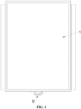
FIG. 1 is a schematic top view of a battery pack according to some embodiments of the present disclosure. -
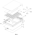
FIG. 2 is a schematic exploded view of the battery pack according to some embodiments of the present disclosure. -
FIG. 3 is a schematic cross-section view of a beam structure along a length direction of the beam structure according to some embodiments of the present disclosure. -
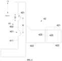
FIG. 4 is a schematic cross-section view of a beam structure along the length direction of the beam structure according to some embodiments of the present disclosure. -
FIG. 5 is a schematic cross-section view of a crossbeam along a length direction of the crossbeam according to some embodiments of the present disclosure. -
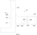
FIG. 6 is a schematic cross-section view of a beam structure along a length direction of the beam structure according to some embodiments of the present disclosure. - In the drawings:
100, battery box; 1, top cover; 2, busbar assembly; 3, battery cell; 4, box body; 4a, side beam; 400, beam structure; 40, corrugated structure; 401, corrugated groove; 402, compression section; 403, deformation section; 41, support section; 411, inner plate; 412, outer plate; 413, first support plate; 414, second support plate; 415, third support plate; 416, connecting plate; 410a, step; 42, hoisting portion; 420, longitudinal-plate section; 421, first connecting section; 422, second connecting section; 423, second longitudinal-plate section; 424, first longitudinal-plate section; 4241, longitudinal section; 4242, oblique section; 425, reinforcing rib; 426, groove structure; 5, liquid-cooling plate; 51, water inlet and outlet; 6, bottom guard plate; 7, crossbeam; 71, side wall; I, first cavity; II, second cavity. - In the description of the present disclosure, it should be noted that, orientations or positional relationships indicated by terms "up", down", "front", "rear", "left", "right", "vertical", "horizontal", "top ", "bottom", "inside", "outside", etc., are based on the orientations or positional relationships shown in the accompanying drawings, and are merely for convenience of describing the present disclosure and simplifying the description, rather than implying or indicating that the device or the component referred to must have a particular orientation or constructed and operated in a particular orientation, and thus these terms cannot be understood as limiting the present disclosure.
- Unless otherwise defined, technical and scientific terms used herein have the same meanings as generally understood by those skilled in the art of the present disclosure. The terms used in the description of the present disclosure are for the purpose of describing specific embodiments only and are not intended to limit the present disclosure.
- As shown in
FIG. 3 andFIG. 4 , abeam structure 400 is disclosed in some embodiments of the present disclosure. Thebeam structure 400 is applied to or used in abattery box 100, and for example, applied to aside beam 4a of thebattery box 100. Abattery cell 3 may be received or installed in thebattery box 100. As shown inFIG. 2 andFIG. 3 , asupport portion 41 is disposed at a side of thebeam structure 400 that is close to thebattery cell 3. A hoistingportion 42 is disposed at a side of thesupport portion 41 that is away from thebattery cell 3. Thesupport portion 41 herein is configured to form or enclose a cavity configured to assemble or receive thebattery cell 3. The hoistingportion 42 is configured to assemble or install thebattery box 100 to an electrical device. - In the related art, the battery box mostly adopts aluminum extrusion profiles to form the beam structure that is included in the box body. The manufacturing process of the extrusion aluminum profiles is simple, but the material cost is higher. Besides, the battery box made of aluminum profiles has a low structural strength. In a case that the battery box is subjected to an external force, the beam structure of the box body is prone to be deformed plastically and squeeze a storage space of the battery cell in the battery box; and in an extreme case, it may even cause a thermal runaway of the battery cell. Based on this, the beam structure of some embodiments of the present disclosure is formed by a steel plate by means of roll forming, i.e., the beam structure of the some embodiments of the present disclosure is a roll-formed steel plate. The beam structure formed by the roll-formed steel plate has a high structural strength. Compared with the traditional aluminum profiles, the beam structure of some embodiments of the present disclosure may better resist deformation when being subjected to the external force, and the safety of the
battery cell 3 in the battery box is ensured. - In some embodiments, the
support portion 41 includes aninner plate 411 and anouter plate 412 arranged oppositely to each other. A first cavity I is defined between theinner plate 411 and theouter plate 412. Theinner plate 411 is arranged at a side of thesupport portion 41 facing thebattery cell 3. That is, theinner plate 411 is arranged towards or faces thebattery cell 3. At least part of theinner plate 411 is configured with acorrugated structure 40. As shown inFIG. 3 , thecorrugated structure 40 configured on theinner plate 411 makes theinner plate 411 have a good elastic deformation ability when theinner plate 411 is subjected to an external force. When the volume of thebattery cell 3 is cyclically expanded in the charging and discharging processes and thebattery cell 3 acts on theinner plate 411, thecorrugated structure 40 configured on theinner plate 411 may absorb the cyclic expansion deformation of thebattery cell 3 through elastic deformation, such that thebattery cell 3 may be arranged as close as possible to theinner plate 411, that is, thebeam structure 400. On one hand, the stability of the assembly of thebattery cell 3 in thebattery box 100 may be improved; and on the other hand, the volume of thebattery box 100 may be reduced. - In some embodiments, when the
battery cell 3 is expanded, thecorrugated structure 40 configured on theinner plate 411 is compressed and elastically deformed towards theouter plate 412, to absorb the expansion and deformation of thebattery cell 3. When the expansion of thebattery cell 3 disappears, thecorrugated structure 40 configured on theinner plate 411 is reset, in order to support thebattery cell 3, so as to ensure the structural stability of the assembly of thebattery cell 3 inbattery box 100. In some embodiments, thecorrugated structure 40 configured on theinner plate 411 may maintain the structural stability of the assembly of thebattery cell 3 in thebattery box 100 along with the cyclic expansion of thebattery cell 3, and the volume of thebattery box 100 may be effectively reduced. - As shown in
FIG. 3 , thecorrugated structure 40 has or defines one or morecorrugated grooves 401. The one or morecorrugated grooves 401 are recessed towards theouter plate 412. The one or morecorrugated grooves 401 recessed towards theouter plate 412 may ensure that a contact area between theinner plate 411 and thebattery cell 3 is sufficiently large. In some embodiments, regions at both sides of each of the one or morecorrugated grooves 401 defined on theinner plate 411 may be in contact with thebattery cell 3. The regions at both sides of each of the one or morecorrugated grooves 401 defined on theinner plate 411 are planar structures. In this way, the contact area between theinner plate 411 and thebattery cell 3 is sufficiently, such that the structural stability of the assembly of thebattery cell 3 in thebattery box 100 may be ensured. Besides, when thebattery cell 3 is expanded and in contact with theinner plate 411, a pressure applied to thebattery cell 3 after the planar structures are in contact with a side surface of thebattery cell 3 is small, and the safety is high. Moreover, the one or morecorrugated grooves 401 are recessed towards theouter plate 412, such that a space where a structure of theinner plate 411 defining the one or morecorrugated grooves 401 is located in the first cavity I. The volume of the cavity defined in thebattery box 100 and configured to assembly or receive thebattery cell 3 may be ensured, such that the purpose of reducing a volume of thebattery box 100 in case that the number ofbattery cells 3 keeps unchanged may be achieved. - Further, the number of the one or more
corrugated grooves 401 is at least two, or the one or morecorrugated grooves 401 have at least twocorrugated grooves 401. The at least twocorrugated grooves 401 are arranged at intervals or spaced apart from each other. In this way, the processing of thecorrugated grooves 401 may be facilitated, for example, the continuous rolling of the steel plate may be facilitated. Besides, a region defined between adjacent two of thecorrugated grooves 401 may be well elastically deformed when thebattery cell 3 is expanded, in order to absorb the deformation of thebattery cell 3. - In some embodiments, a region of the
inner plate 411 where each of the at least twocorrugated grooves 401 is located is defined as adeformation section 403. An interval region between adjacent twodeformation sections 403 is defined as acompression section 402 or pressurized section. An arc transition is configured between thecompression section 402 and each of thedeformation sections 403. In the cyclic expansion process of thebattery cell 3, thedeformation section 403 may be elastically deformed, and thecompression section 402 is subjected to direct extrusion from thebattery cell 3. Under the action of thedeformation section 403, thecompression section 402, as a whole, moves towards the outer plate (during the expansion of the volume of the battery cell 3) or away from (during the recovery of the volume of the battery cell 3) theouter plate 412. The arc transition between thecompression section 402 and each of thedeformation sections 403 may reduce a stress at a junction between thecompression section 402 and the each of thedeformation sections 403, which ensures the structural strength of theinner plate 411, and reduces the tearing and damage to the junction between thecompression section 402 and each of thedeformation sections 403 of thecorrugated structure 40 during the cyclic expansion of thebattery cell 3. - In some embodiments, an extension direction of each of the one or more
corrugated grooves 401 is parallel to a length direction of thebeam structure 400. - In some embodiments, the
inner plate 411 is parallel to theouter plate 412. - As shown in
FIG. 4 , a distance between adjacent two of the at least twocorrugated grooves 401 is defined as H. The maximum width of each of thecorrugated grooves 401 is defined as D, and 0.4≤D/H≤1.2. In this way, the layout of thecorrugated grooves 401 and thecompression section 402 is more reasonable, such that thecorrugated structure 40 may be deformed within a reasonable range in the process that thebattery cell 3 squeezes theinner plate 411, without affecting the structural strength of theinner plate 411. In other words, when 0.4≤D/H≤1.2, thecorrugated structure 40 makes theinner plate 411 be able to produce elastic deformation without plastic deformation when theinner plate 411 is compressed. In this way, the safety of thebeam structure 400 is ensured when thebeam structure 400 absorbs the expansion and deformation of thebattery cell 3. - In some embodiments, 20mm≤D≤60mm. In some embodiments, H = 50 mm. In some embodiments, D=20mm.
- It should be noted that, the maximum width of each of the
corrugated grooves 401 refers to the maximum straight-line distance between two points on the inner wall of the correspondingcorrugated groove 401 in the up-down direction shown inFIG. 4 . - As shown in
FIG. 3 , thebeam structure 400 further includes afirst support plate 413 and asecond support plate 414. In some embodiments, thefirst support plate 413 is connected to theinner plate 411 and is extended from theinner plate 411 towards a side that deviates or is away from theouter plate 412. Thesecond support plate 414 is connected to theouter plate 412. An extension direction of thesecond support plate 414 is the same as an extension direction of thefirst support plate 413. That is, thesecond support plate 414 is extended from theouter plate 412 in a direction towards or facing thebattery cell 3. Thefirst support plate 413 is connected to thesecond support plate 414 at a distal end of thefirst support plate 413 in the extension direction thereof; in other words, a distal end of thefirst support plate 413 in the extension direction of thefirst support plate 413 is connected to a distal end of thesecond support plate 414 in the extension direction of the second support plate. Herein, the distal end of thefirst support plate 413 refers to the end which is away from theinner plate 411. Likewise, the distal end of thesecond support plate 414 refers to the end which is away from theouter plate 412. In this way, thefirst support plate 413 and thesecond support plate 414 may form astep 410a extending towards thebattery cell 3 at the side of thebeam structure 400 facing thebattery cell 3. That is, in thebattery box 100 formed or enclosed by thebeam structure 400, thestep 410a is formed in the cavity configured to assemble or receive thebattery cell 3, and thestep 410a (formed by thefirst support plate 413 and the second support plate 414) is convenient for assembling acrossbeam 7 in the cavity configured to assemble thebattery cell 3, such that the structural strength of thebattery box 100 is improved. In some embodiments, thecrossbeam 7 is lapped on thestep 410a. In some embodiments, thecrossbeam 7 and thestep 410a are fixedly connected to each other, for example, by means of welding or bolting. - In some embodiments, a second cavity II is defined between the
first support plate 413 and thesecond support plate 414. The first cavity I is fluidly connected to or communicates with the second cavity II. This arrangement facilitates the continuous roll forming of thesupport section 41. - Further, the
beam structure 400 further includes athird support plate 415. Thethird support plate 415 is integrally connected to an end of theouter plate 412 away from thesecond support plate 414. Theinner plate 411 is connected to thethird support plate 415. In some embodiments, thethird support plate 415 is configured to seal the first cavity I at one end away from thefirst support plate 413 or thesecond support plate 414. In some embodiments, thethird support plate 415 is integrally formed with theouter plate 412. Thethird support plate 415 is used as the starting section or the end section of the roll-formed steel plate of thesupport portion 41, and is welded with theinner plate 411. - In some embodiments, the
first support plate 413, thesecond support plate 414, and thethird support plate 415 are parallel to each other. - In some embodiments, the
second support plate 414 and thefirst support plate 413 are integrally connected to each other through a connectingplate 416. In some embodiments, the connectingplate 416 is parallel to theinner plate 411 and theouter plate 412. - In some embodiments, the
aforesaid hoisting portion 42 is formed of a steel plate by means of roll forming. The hoistingportion 42 includes a first connectingsection 421 and at least two second connectingsections 422. The at least two second connectingsections 422 are connected to each other and are disposed on the same side of the first connectingsection 421. The at least two second connectingsections 422 are spaced apart from the first connectingsection 421. The at least two second connectingsections 422 cooperatively correspond to the first connectingsection 421. The first connectingsection 421 may be called as "integral-plate section", and the second connectingsection 422 may be called as "split-plate section". In some embodiments, the first connectingsection 421 and the second connectingsection 422 are extended in a horizontal direction. At least one of the second connectingsections 422 is arranged with a reinforcingrib 425. The reinforcingrib 425 abuts against the first connectingsection 421. As shown inFIG. 3 , two second connectingsections 422 are taken as an example for illustration. In some embodiments, one of the two second connectingsections 422 is arranged with the reinforcingrib 425. The two second connectingsections 422 are integrally formed with the first connectingsection 421, respectively. The two second connectingsections 422 are the beginning section and the end sections of the hoistingportion 42, respectively. The reinforcingrib 425 may be, but not limited to, Z-type, S-type, C-type, etc. The reinforcingrib 425 here may effectively improve the structural strength of the hoistingportion 42. When the hoistingportion 42 is impacted by an external force, the reinforcingrib 425 may absorb the impact energy, and thebattery cell 3 in thebattery box 100 body is well protected. - In another embodiments, each of two second connecting
sections 422 is arranged with a C-type reinforcing rib 425. As shown inFIG. 4 , the reinforcingrib 425 arranged on each of two second connectingsections 422 abuts against the first connectingsection 421. The reinforcingribs 425 arranged on the two second connectingsections 422 are connected to each other. In some embodiments, the structural design of the two reinforcingribs 425 may further improve the structural strength of the hoistingportion 42. - In an additional embodiments, the number of the second connecting
sections 42 may also be set as three. As shown inFIG. 6 , two of the three second connectingsections 422 close to or adjacent to theouter plate 412 are arranged in a step, such that the hoistingportion 42 forms agroove structure 426. When in use, a reinforcing member (not shown in the drawings) may be mounted in thegroove structure 426. The reinforcing member may be a reinforcing beam or a reinforcing block which has a shape matching a shape of thegroove structure 426. The reinforcing member is welded with or bonded to an inner wall of thegroove structure 426, such that the structural strength of the hoistingportion 42 is improved. - Further, the hoisting
portion 42 further includes one or more longitudinal-plate sections 420. The one or more longitudinal-plate sections 420 are integrally connected between the first connectingsection 421 and the second connectingsection 422. In some embodiments, as shown inFIG. 3 , the number of the longitudinal-plate sections 420 may be at least two. The longitudinal-plate sections 420 include a first longitudinal-plate section 424 disposed close to theouter plate 412 and connected to theouter plate 412.. The longitudinal-plate sections includes a second longitudinal-plate section 423 disposed away from theouter plate 412 and is disconnected from theouter plate 412. The first longitudinal-plate section 424 is spaced apart from the second longitudinal-plate section 423. In some embodiments, the first longitudinal-plate section 424 is parallel to the second longitudinal-plate section 423. In some embodiments, the first longitudinal-plate section 424 includes alongitudinal section 4241 and anoblique section 4242 integrally connected to each other. Thelongitudinal section 4241 is connected to theouter plate 412. Thelongitudinal section 4241 is connected to the first connectingsection 421 and/or the corresponding second connectingsection 422 through theoblique section 4242. Theoblique section 4242 and thelongitudinal section 4241 are arranged at an angle. The angle between theoblique section 4242 and thelongitudinal section 4241 is an acute angle. In some embodiments, thelongitudinal section 4241 is welded with theouter plate 412. The angle between theoblique section 4242 and thelongitudinal section 4241 is a, and 0°<α<90°. In some embodiments, α=45°. This arrangement may effectively disperse the stress applied between thesupport portion 41 and hoistingportion 42 of thebeam structure 400, and thus, the effect of improving strength of thebeam structure 400 may be achieved. - In some embodiments, the first connecting
section 421 is parallel to the second connectingsections 422. Thelongitudinal section 4241 is perpendicular to the first connectingsection 421. - In some embodiments, as shown in
FIG. 3 , theoblique section 4242 is located on a side of the hoistingportion 42 where the first connectingsection 421 is located. In some embodiments, theoblique section 4242 may also be arranged on a side of the hoistingportion 42 where the second connectingsection 422 is located. In other embodiments, theoblique section 4242 may be arranged on both sides of the hoistingportion 42 where the first connectingsection 421 and the second connectingsection 422 are located, that is, two ends of thelongitudinal section 4241 are provided with theoblique sections 4242. In this way, the stress applied to thebeam structure 400 may be better dispersed and the strength of thebeam structure 400 is ensured. - In some embodiments, an orthographic projection of the
longitudinal section 4241 in the length direction of thebeam structure 400 is parallel to an orthographic projection of theouter plate 412 in the length direction of thebeam structure 400. Thelongitudinal section 4241 and theouter plate 412 are parallel to each other. In this way, after thelongitudinal section 4241 is attached to theouter plate 412, the contact area between thelongitudinal section 4241 and theouter plate 412 is large, and the connection strength is high. - As shown in
FIG. 1 andFIG. 2 , abattery box 100 is also provided in some embodiments of the present disclosure. Thebattery box 100 includes thebeam structure 400 described above. In some embodiments, thebattery box 100 includes abox body 4. Thebox body 4 is formed by fourside beams 4a connected end-to-end. In some embodiments, each of theside beams 4a in the left and right directions includes thesupport portion 41 and the hoistingportion 42 of theaforementioned beam structure 400. Each of theside beams 4a in the front and rear directions only includes thesupport portion 41 of theaforesaid beam structure 400. Thebattery box 100 has a high structural strength and low cost, and may well absorb the expansion and deformation of thebattery cell 3. - Further, the
box body 4 further includes thecrossbeam 7. Thecross beam 7 is connected to theside beams 4a. In some embodiments, thecrossbeam 7 is connected to thestep 410a formed by thefirst support plate 413 and thesecond support plate 414 described above. It should be noted that thecrossbeam 7 is arranged in the middle of the cavity. In some embodiments, thecrossbeam 7 is arranged with acorrugated structure 40 at at least oneside wall 71 facing thebattery cell 3. In some embodiments, as shown inFIG. 5 , thecrossbeam 7 includes twoside walls 71 arranged oppositely to each other. The twoside walls 71 are both configured with the aforementionedcorrugated structure 40. In this way, when thebattery cell 3 is cyclically expanded, thecrossbeam 7 may also follow the cyclic expansion of thebattery cell 3 through thecorrugated structure 40, so as to absorb the cyclic expansion and deformation of thebattery cell 3. Thecrossbeam 7 here is a rolling-formed steel plate. - A cross-sectional shape of each of the one or more
corrugated grooves 401 is semicircular, trapezoidal, or triangular. - It should be noted that the
corrugated groove 401 is not limited to a round or circular groove. Thecorrugated groove 401 may also be trapezoidal groove, a triangular groove, etc. When thecorrugated groove 401 is the trapezoidal groove or the triangular groove, a filleted corner may be configured at a position where a vertex angle is located, such that the stress concentration may be reduced. - In another embodiments, the
corrugated structure 40 may also be a wave-shaped structure. - The
battery box 100 further includes a liquid-cooling plate 5 and abottom guard plate 6 that are successively arranged at a lower side of thebox body 4. Water inlet andoutlets 51 of the liquid-cooling plate 5 are arranged at an outer side of thebox body 4. In this way, the probability that the liquid-cooling plate 5 leaks in the cavity configured to assemble thebattery cell 3 may be reduced, and the safety is high. - The
battery box 100 further includes atop cover 1 arranged at an upper side of thebox body 4. - As shown in
FIG. 1 andFIG. 2 , a battery pack is further provided in some embodiments of the present disclosure. The battery pack includes thebattery cell 3, abusbar assembly 2, and theaforesaid battery box 100. Thebattery cell 3 is arranged in thebattery box 100, and thebusbar assembly 2 is arranged at the top of thebattery cell 3 and is located at the lower side of thetop cover 1. The battery pack is compact and safe.
Claims (15)
- A beam structure (400) for a battery box (100), the battery box (100) being configured to receive a battery cell (3), and the beam structure (400) comprising:an inner plate (411); andan outer plate (412), arranged oppositely to the inner plate (411);wherein a first cavity (I) is defined between the inner plate (411) and the outer plate (412), the inner plate (411) is configured to be arranged at a side facing the battery cell (3); andwherein at least part of the inner plate (411) is configured with a corrugated structure (40).
- The beam structure (400) as claimed in claim 1, wherein the corrugated structure (40) has one or more corrugated grooves (401), and the one or more corrugated grooves (401) are recessed toward the outer plate (412).
- The beam structure (400) as claimed in claim 2, wherein the one or more corrugated grooves (401) comprise at least two corrugated grooves (401), and the at least two corrugated grooves (401) are arranged at intervals.
- The beam structure (400) as claimed in claim 3, wherein a region on the inner plate (411) where each of the at least two corrugated grooves (401) is located is defined as a deformation section (403); and
wherein an interval region between adjacent two of the deformation sections (403) is a compression section (402), and an arc transition is configured between the compression section (402) and each of the deformation sections (403). - The beam structure (400) as claimed in claim 3, wherein a distance between adjacent two of the at least two corrugated grooves (401) is defined as H, the maximum width of each of the at least two corrugated grooves (401) is defined D, and 0.4≤D/H≤1.2.
- The beam structure (400) as claimed in claim 5, wherein D satisfies: 20mm≤D≤60mm.
- The beam structure (400) as claimed in claim 1, wherein the beam structure (400) further comprises a first support plate (413) and a second support plate (414);wherein the first support plate (413) is connected to the inner plate (411) and is extended toward a side of the inner plate (411) that is away from the outer plate (412);the second support plate (414) is connected to the outer plate (412), and an extension direction of the second support plate (414) is the same as that of the first support plate (413); andwherein an end of the first support plate (413) away from the inner plate (411) is connected to an end of the second support plate (414) away from the outer plate (412).
- The beam structure (400) as claimed in claim 7, wherein a second cavity (II) is defined between the first support plate (413) and the second support plate (414), and the first cavity (I) is fluidly connected to the second cavity (II).
- The beam structure (400) as claimed in claim 7, wherein the beam structure (400) further comprises a third support plate (415), the third support plate (415) is integrally connected to an end of the outer plate (412) away from the second support plate (414), and the inner plate (411) is connected to the third support plate (415).
- The beam structure (400) as claimed in any one of claims 1-9, wherein a hoisting portion (42) is arranged on a side of the outer plate (412) away from the inner plate (411), and the hoisting portion (42) is roll-formed;the hoisting portion (42) comprises an first connecting section (421) and at least two second connecting sections (422), and the at least two second connecting sections (422) are connected to each other and are on the same side of the first connecting section (421); andwherein at least one of the at least two second connecting sections (422) is arranged with a reinforcing rib (425), and the reinforcing rib (425) abuts against the first connecting section (421).
- The beam structure (400) as claimed in claim 10, wherein the hoisting portion (42) further comprises at least two longitudinal-plate sections (420), and the at least two longitudinal-plate sections (420) are integrally connected between the first connecting section (421);the at least two longitudinal-plate sections (420) comprises a first longitudinal-plate section (424) arranged adjacent to the outer plate (412) and connected to the outer plate (412), and a second longitudinal-plate section (423) away from the outer plate (412);the first longitudinal-plate section (424) comprises a longitudinal section (4241) and an oblique section (4242) integrally connected to each other, the longitudinal section (4241) is connected to the outer plate (412), and the longitudinal section (4241) is connected to the first connecting section (421) and/or a corresponding one of the at least two second connecting sections (422) through the oblique section (4242); andwherein the oblique section (4242) is arranged at an angle with the longitudinal section (4241), and the angle between the oblique section (4242) and the longitudinal section (4241) is an acute angle.
- The beam structure as claimed in any one of claims 1-9, wherein the beam structure is roll-formed; and/orthe corrugated structure (40) is in a wave shape; and/ora cross-sectional shape of each of the one or more corrugated grooves (401) is semicircular, trapezoidal, or triangular.
- A battery box (100) configured to receive a battery cell (3), the battery box (100) comprising a box body (4), wherein the box body (4) comprises the beam structure (400) as claimed in any one of claims 1-12.
- The battery box as claimed in claim 13, wherein a crossbeam (7) is arranged in the box body (4), and at least one side wall of the crossbeam (7) facing the battery cell is arranged with the corrugated structure (40).
- A battery pack, comprising the battery box (100) as claimed in claim 12 or 13.
Applications Claiming Priority (1)
| Application Number | Priority Date | Filing Date | Title |
|---|---|---|---|
| CN202311332658.8A CN117335072A (en) | 2023-10-13 | 2023-10-13 | Beam structure, battery box and battery pack |
Publications (1)
| Publication Number | Publication Date |
|---|---|
| EP4539224A1 true EP4539224A1 (en) | 2025-04-16 |
Family
ID=89278925
Family Applications (1)
| Application Number | Title | Priority Date | Filing Date |
|---|---|---|---|
| EP24166834.2A Pending EP4539224A1 (en) | 2023-10-13 | 2024-03-27 | Beam structure, battery box, and battery pack |
Country Status (6)
| Country | Link |
|---|---|
| US (1) | US20250125465A1 (en) |
| EP (1) | EP4539224A1 (en) |
| JP (1) | JP2025067776A (en) |
| KR (1) | KR102905055B1 (en) |
| CN (1) | CN117335072A (en) |
| WO (1) | WO2025077118A1 (en) |
Families Citing this family (2)
| Publication number | Priority date | Publication date | Assignee | Title |
|---|---|---|---|---|
| CN117335072A (en) * | 2023-10-13 | 2024-01-02 | 惠州亿纬锂能股份有限公司 | Beam structure, battery box and battery pack |
| CN118040209B (en) * | 2024-02-06 | 2026-01-27 | 宁德时代新能源科技股份有限公司 | Battery and electricity utilization device |
Citations (3)
| Publication number | Priority date | Publication date | Assignee | Title |
|---|---|---|---|---|
| WO2018029168A1 (en) * | 2016-08-12 | 2018-02-15 | Thyssenkrupp Steel Europe Ag | Battery case with lateral reinforcement |
| CN217444536U (en) * | 2022-01-24 | 2022-09-16 | 华为技术有限公司 | Battery pack lower box body, battery pack and electric automobile |
| US20230117003A1 (en) * | 2021-10-19 | 2023-04-20 | GM Global Technology Operations LLC | Steel rocker energy absorption load path development for rechargeable energy storage system protection |
Family Cites Families (17)
| Publication number | Priority date | Publication date | Assignee | Title |
|---|---|---|---|---|
| JP2891072B2 (en) * | 1993-12-07 | 1999-05-17 | 日産自動車株式会社 | Electric car floor structure |
| DE102017121151B4 (en) * | 2017-09-13 | 2025-09-18 | Benteler Automobiltechnik Gmbh | Device for accommodating a plurality of accumulators for the operation of a motor vehicle having an electric drive |
| JP6859933B2 (en) * | 2017-11-17 | 2021-04-14 | トヨタ自動車株式会社 | Vehicle battery case and its manufacturing method |
| US10894469B2 (en) * | 2018-02-19 | 2021-01-19 | Dura Operating, Llc | Automobile vehicle battery tray with roll-formed members |
| CN208674230U (en) * | 2018-09-27 | 2019-03-29 | 北京车和家信息技术有限公司 | Battery pack and its lower box and vehicle |
| JP7220637B2 (en) * | 2019-07-31 | 2023-02-10 | 株式会社神戸製鋼所 | Battery case for electric vehicle and manufacturing method thereof |
| JP7240298B2 (en) * | 2019-10-11 | 2023-03-15 | 株式会社神戸製鋼所 | Method for manufacturing battery case for electric vehicle and battery case for electric vehicle |
| CN111916603B (en) * | 2020-08-07 | 2022-11-04 | 苏州亿创特智能制造有限公司 | Rolled section bar, preparation method thereof, battery pack framework and battery pack |
| CN114583355B (en) * | 2020-11-30 | 2023-06-20 | 宝钢金属有限公司 | A profile used for a new energy vehicle battery pack housing and a manufacturing method thereof |
| CN115472976A (en) * | 2021-06-11 | 2022-12-13 | 威马智慧出行科技(上海)股份有限公司 | Power battery lower box body, power battery and electric vehicle |
| CN215070273U (en) * | 2021-07-20 | 2021-12-07 | 苏州亿创特智能制造有限公司 | Boundary beam |
| EP4123805A1 (en) * | 2021-07-23 | 2023-01-25 | Constellium UK Limited | Battery holder and manufacturing process of said battery holder |
| CN217606965U (en) * | 2022-04-29 | 2022-10-18 | 比亚迪股份有限公司 | A battery tray, battery pack and vehicle |
| CN218569054U (en) * | 2022-09-01 | 2023-03-03 | 天津市捷威动力工业有限公司 | Battery pack lower box body, battery pack and electric device |
| CN218472169U (en) * | 2022-09-27 | 2023-02-10 | 比亚迪股份有限公司 | Battery tray, battery pack and vehicle |
| WO2024225159A1 (en) * | 2023-04-26 | 2024-10-31 | Jfeスチール株式会社 | Battery case |
| CN117335072A (en) * | 2023-10-13 | 2024-01-02 | 惠州亿纬锂能股份有限公司 | Beam structure, battery box and battery pack |
-
2023
- 2023-10-13 CN CN202311332658.8A patent/CN117335072A/en active Pending
-
2024
- 2024-03-27 EP EP24166834.2A patent/EP4539224A1/en active Pending
- 2024-03-28 WO PCT/CN2024/084604 patent/WO2025077118A1/en active Pending
- 2024-04-19 KR KR1020240053012A patent/KR102905055B1/en active Active
- 2024-05-20 JP JP2024081782A patent/JP2025067776A/en active Pending
- 2024-06-03 US US18/731,368 patent/US20250125465A1/en active Pending
Patent Citations (3)
| Publication number | Priority date | Publication date | Assignee | Title |
|---|---|---|---|---|
| WO2018029168A1 (en) * | 2016-08-12 | 2018-02-15 | Thyssenkrupp Steel Europe Ag | Battery case with lateral reinforcement |
| US20230117003A1 (en) * | 2021-10-19 | 2023-04-20 | GM Global Technology Operations LLC | Steel rocker energy absorption load path development for rechargeable energy storage system protection |
| CN217444536U (en) * | 2022-01-24 | 2022-09-16 | 华为技术有限公司 | Battery pack lower box body, battery pack and electric automobile |
Also Published As
| Publication number | Publication date |
|---|---|
| CN117335072A (en) | 2024-01-02 |
| JP2025067776A (en) | 2025-04-24 |
| US20250125465A1 (en) | 2025-04-17 |
| WO2025077118A1 (en) | 2025-04-17 |
| KR20250053685A (en) | 2025-04-22 |
| KR102905055B1 (en) | 2025-12-29 |
Similar Documents
| Publication | Publication Date | Title |
|---|---|---|
| US20250125465A1 (en) | Beam structure, battery box, and battery pack | |
| US10916792B2 (en) | Fuel cell stack | |
| KR20220092581A (en) | Devices using battery modules, battery packs and secondary batteries | |
| US10840485B2 (en) | Composite end plate and battery module | |
| US20200274174A1 (en) | Fuel cell joint separator and fuel cell | |
| CN114865205A (en) | Solid-state battery module and battery pack | |
| CN221102263U (en) | Beam structure, battery box and battery pack | |
| CN119133731A (en) | Battery cells, metal housings and electrical equipment | |
| KR101256058B1 (en) | Secondary battery module | |
| US10741816B2 (en) | Battery module | |
| CN118970338B (en) | Battery box | |
| CN219436039U (en) | Box, battery and power consumption device | |
| CN117134075A (en) | A flat plate connecting aluminum bar and battery core module | |
| CN218070031U (en) | Battery pack beam assembly | |
| CN120021081A (en) | Battery box, battery box manufacturing method, battery and power-using device | |
| CN217606965U (en) | A battery tray, battery pack and vehicle | |
| CN220984731U (en) | Battery box and power battery | |
| CN219658881U (en) | Box structure and battery pack | |
| CN223539792U (en) | Battery pack and its side panel assembly, housing, vehicle | |
| CN222637440U (en) | Shell, battery monomer, battery and power consumption device | |
| CN220382208U (en) | Battery pack tray and battery pack | |
| CN222813828U (en) | Battery devices and electrical equipment | |
| CN219286572U (en) | Battery box and battery pack | |
| CN223993351U (en) | Battery device and electric equipment | |
| CN221080241U (en) | Battery box cover, battery box and battery pack |
Legal Events
| Date | Code | Title | Description |
|---|---|---|---|
| PUAI | Public reference made under article 153(3) epc to a published international application that has entered the european phase |
Free format text: ORIGINAL CODE: 0009012 |
|
| STAA | Information on the status of an ep patent application or granted ep patent |
Free format text: STATUS: EXAMINATION IS IN PROGRESS |
|
| 17P | Request for examination filed |
Effective date: 20240327 |
|
| AK | Designated contracting states |
Kind code of ref document: A1 Designated state(s): AL AT BE BG CH CY CZ DE DK EE ES FI FR GB GR HR HU IE IS IT LI LT LU LV MC ME MK MT NL NO PL PT RO RS SE SI SK SM TR |