EP4539222A2 - Cells contact system (ccs) assembly, battery module, battery, and electrical device - Google Patents
Cells contact system (ccs) assembly, battery module, battery, and electrical device Download PDFInfo
- Publication number
- EP4539222A2 EP4539222A2 EP24206329.5A EP24206329A EP4539222A2 EP 4539222 A2 EP4539222 A2 EP 4539222A2 EP 24206329 A EP24206329 A EP 24206329A EP 4539222 A2 EP4539222 A2 EP 4539222A2
- Authority
- EP
- European Patent Office
- Prior art keywords
- bus bar
- insulating bracket
- battery
- grooves
- groove
- Prior art date
- Legal status (The legal status is an assumption and is not a legal conclusion. Google has not performed a legal analysis and makes no representation as to the accuracy of the status listed.)
- Pending
Links
Images








Classifications
-
- H—ELECTRICITY
- H01—ELECTRIC ELEMENTS
- H01M—PROCESSES OR MEANS, e.g. BATTERIES, FOR THE DIRECT CONVERSION OF CHEMICAL ENERGY INTO ELECTRICAL ENERGY
- H01M50/00—Constructional details or processes of manufacture of the non-active parts of electrochemical cells other than fuel cells, e.g. hybrid cells
- H01M50/20—Mountings; Secondary casings or frames; Racks, modules or packs; Suspension devices; Shock absorbers; Transport or carrying devices; Holders
- H01M50/204—Racks, modules or packs for multiple batteries or multiple cells
-
- H—ELECTRICITY
- H01—ELECTRIC ELEMENTS
- H01M—PROCESSES OR MEANS, e.g. BATTERIES, FOR THE DIRECT CONVERSION OF CHEMICAL ENERGY INTO ELECTRICAL ENERGY
- H01M50/00—Constructional details or processes of manufacture of the non-active parts of electrochemical cells other than fuel cells, e.g. hybrid cells
- H01M50/20—Mountings; Secondary casings or frames; Racks, modules or packs; Suspension devices; Shock absorbers; Transport or carrying devices; Holders
- H01M50/249—Mountings; Secondary casings or frames; Racks, modules or packs; Suspension devices; Shock absorbers; Transport or carrying devices; Holders specially adapted for aircraft or vehicles, e.g. cars or trains
-
- H—ELECTRICITY
- H01—ELECTRIC ELEMENTS
- H01M—PROCESSES OR MEANS, e.g. BATTERIES, FOR THE DIRECT CONVERSION OF CHEMICAL ENERGY INTO ELECTRICAL ENERGY
- H01M50/00—Constructional details or processes of manufacture of the non-active parts of electrochemical cells other than fuel cells, e.g. hybrid cells
- H01M50/20—Mountings; Secondary casings or frames; Racks, modules or packs; Suspension devices; Shock absorbers; Transport or carrying devices; Holders
- H01M50/258—Modular batteries; Casings provided with means for assembling
-
- H—ELECTRICITY
- H01—ELECTRIC ELEMENTS
- H01M—PROCESSES OR MEANS, e.g. BATTERIES, FOR THE DIRECT CONVERSION OF CHEMICAL ENERGY INTO ELECTRICAL ENERGY
- H01M50/00—Constructional details or processes of manufacture of the non-active parts of electrochemical cells other than fuel cells, e.g. hybrid cells
- H01M50/20—Mountings; Secondary casings or frames; Racks, modules or packs; Suspension devices; Shock absorbers; Transport or carrying devices; Holders
- H01M50/262—Mountings; Secondary casings or frames; Racks, modules or packs; Suspension devices; Shock absorbers; Transport or carrying devices; Holders with fastening means, e.g. locks
- H01M50/264—Mountings; Secondary casings or frames; Racks, modules or packs; Suspension devices; Shock absorbers; Transport or carrying devices; Holders with fastening means, e.g. locks for cells or batteries, e.g. straps, tie rods or peripheral frames
-
- H—ELECTRICITY
- H01—ELECTRIC ELEMENTS
- H01M—PROCESSES OR MEANS, e.g. BATTERIES, FOR THE DIRECT CONVERSION OF CHEMICAL ENERGY INTO ELECTRICAL ENERGY
- H01M50/00—Constructional details or processes of manufacture of the non-active parts of electrochemical cells other than fuel cells, e.g. hybrid cells
- H01M50/20—Mountings; Secondary casings or frames; Racks, modules or packs; Suspension devices; Shock absorbers; Transport or carrying devices; Holders
- H01M50/284—Mountings; Secondary casings or frames; Racks, modules or packs; Suspension devices; Shock absorbers; Transport or carrying devices; Holders with incorporated circuit boards, e.g. printed circuit boards [PCB]
-
- H—ELECTRICITY
- H01—ELECTRIC ELEMENTS
- H01M—PROCESSES OR MEANS, e.g. BATTERIES, FOR THE DIRECT CONVERSION OF CHEMICAL ENERGY INTO ELECTRICAL ENERGY
- H01M50/00—Constructional details or processes of manufacture of the non-active parts of electrochemical cells other than fuel cells, e.g. hybrid cells
- H01M50/50—Current conducting connections for cells or batteries
- H01M50/502—Interconnectors for connecting terminals of adjacent batteries; Interconnectors for connecting cells outside a battery casing
- H01M50/507—Interconnectors for connecting terminals of adjacent batteries; Interconnectors for connecting cells outside a battery casing comprising an arrangement of two or more busbars within a container structure, e.g. busbar modules
-
- H—ELECTRICITY
- H01—ELECTRIC ELEMENTS
- H01M—PROCESSES OR MEANS, e.g. BATTERIES, FOR THE DIRECT CONVERSION OF CHEMICAL ENERGY INTO ELECTRICAL ENERGY
- H01M50/00—Constructional details or processes of manufacture of the non-active parts of electrochemical cells other than fuel cells, e.g. hybrid cells
- H01M50/50—Current conducting connections for cells or batteries
- H01M50/502—Interconnectors for connecting terminals of adjacent batteries; Interconnectors for connecting cells outside a battery casing
- H01M50/514—Methods for interconnecting adjacent batteries or cells
- H01M50/517—Methods for interconnecting adjacent batteries or cells by fixing means, e.g. screws, rivets or bolts
-
- H—ELECTRICITY
- H01—ELECTRIC ELEMENTS
- H01M—PROCESSES OR MEANS, e.g. BATTERIES, FOR THE DIRECT CONVERSION OF CHEMICAL ENERGY INTO ELECTRICAL ENERGY
- H01M50/00—Constructional details or processes of manufacture of the non-active parts of electrochemical cells other than fuel cells, e.g. hybrid cells
- H01M50/50—Current conducting connections for cells or batteries
- H01M50/502—Interconnectors for connecting terminals of adjacent batteries; Interconnectors for connecting cells outside a battery casing
- H01M50/519—Interconnectors for connecting terminals of adjacent batteries; Interconnectors for connecting cells outside a battery casing comprising printed circuit boards [PCB]
-
- H—ELECTRICITY
- H01—ELECTRIC ELEMENTS
- H01M—PROCESSES OR MEANS, e.g. BATTERIES, FOR THE DIRECT CONVERSION OF CHEMICAL ENERGY INTO ELECTRICAL ENERGY
- H01M2220/00—Batteries for particular applications
- H01M2220/20—Batteries in motive systems, e.g. vehicle, ship, plane
-
- H—ELECTRICITY
- H01—ELECTRIC ELEMENTS
- H01M—PROCESSES OR MEANS, e.g. BATTERIES, FOR THE DIRECT CONVERSION OF CHEMICAL ENERGY INTO ELECTRICAL ENERGY
- H01M50/00—Constructional details or processes of manufacture of the non-active parts of electrochemical cells other than fuel cells, e.g. hybrid cells
- H01M50/20—Mountings; Secondary casings or frames; Racks, modules or packs; Suspension devices; Shock absorbers; Transport or carrying devices; Holders
- H01M50/204—Racks, modules or packs for multiple batteries or multiple cells
- H01M50/207—Racks, modules or packs for multiple batteries or multiple cells characterised by their shape
- H01M50/213—Racks, modules or packs for multiple batteries or multiple cells characterised by their shape adapted for cells having curved cross-section, e.g. round or elliptic
-
- Y—GENERAL TAGGING OF NEW TECHNOLOGICAL DEVELOPMENTS; GENERAL TAGGING OF CROSS-SECTIONAL TECHNOLOGIES SPANNING OVER SEVERAL SECTIONS OF THE IPC; TECHNICAL SUBJECTS COVERED BY FORMER USPC CROSS-REFERENCE ART COLLECTIONS [XRACs] AND DIGESTS
- Y02—TECHNOLOGIES OR APPLICATIONS FOR MITIGATION OR ADAPTATION AGAINST CLIMATE CHANGE
- Y02E—REDUCTION OF GREENHOUSE GAS [GHG] EMISSIONS, RELATED TO ENERGY GENERATION, TRANSMISSION OR DISTRIBUTION
- Y02E60/00—Enabling technologies; Technologies with a potential or indirect contribution to GHG emissions mitigation
- Y02E60/10—Energy storage using batteries
Definitions
- the present disclosure relates to the technical field of batteries, in particular to a cells contact system (CCS) assembly, a battery module, a battery and an electrical device.
- CCS cells contact system
- operating signals of a battery module are collected by a CCS assembly.
- the CCS assembly includes a plastic bracket and an output bus bar, a series bus bar and a flexible printed circuit (FPC) board mounted on the plastic bracket.
- the FPC board is electrically connected to the output bus bar, the series bus bar, and a battery management system (BMS) board.
- BMS battery management system
- a plurality of cells are mounted on the plastic bracket.
- the bus bar is arranged on one side of the plastic bracket and welded with the poles of the cells.
- the positional accuracy of the bus bar is poor, resulting in low alignment accuracy between the bus bar and the poles of the cells.
- the low alignment accuracy leads to poor welding reliability between the bus bar and the poles of the cells.
- Embodiments of the present disclosure provide a CCS assembly, a battery module, a battery and an electrical device, which may improve the positional accuracy of a bus bar.
- the alignment accuracy of the bus bar and poles of a plurality of cells may be improved. Poor welding reliability between the bus bar and the poles of the cells may be improved.
- the CCS assembly includes a first insulating bracket, at least a bus bar, and an FPC.
- a first insulating bracket is configured to mount a plurality of cells and is provided with at least a positioning post.
- the bus bar is configured to be connected to the cells.
- the bus bar is arranged on the first insulating bracket and is provided with a first through hole.
- the bus bar is sleeved on the positioning post through the first through hole.
- the FPC board is connected to the bus bar and is configured to transmit operating signals of the bus bar to the BMS board.
- the battery module provided by the present disclosure includes a second insulating bracket, a plurality of cells, a battery management system (BMS), and the above CCS assembly.
- the second insulating bracket is disposed opposite to the first insulating bracket.
- the cells are arranged between the first insulating bracket and the second insulating bracket.
- the cells are connected to the bus bar.
- the BMS board is connected to the FPC board.
- the bus bar is positioned according to the positioning post.
- the positional accuracy of the bus bar mounted on the first insulating bracket is improved, and the alignment accuracy of the bus bar and poles of the cells mounted on the first insulating bracket is improved. Poor welding reliability between the bus bar and the poles of the cells is improved.
- the plastic bracket on which the cells are mounted may not position the bus bar, which leads to low accuracy of the installation position of the bus bar, resulting in low alignment accuracy between the bus bar and the poles of the cells.
- the low alignment accuracy leads to poor welding reliability between the bus bar and the poles of the cells.
- the embodiments of the present disclosure provide a CCS assembly, a battery module, a battery, and an electrical device.
- the electrical device may be electric toys, electric tools, electromobiles, automobiles, ships, spacecraft, etc.
- the automobile may be a fuel vehicle, a hybrid vehicle or a pure electric vehicle, etc.
- An FPC board in the embodiments of the present disclosure refers to a flexible printed circuit board, also referred to as a flexible or soft circuit board. It is a circuit board made using a flexible substrate that may be bent and folded in three dimensions to accommodate a variety of applications with special shapes and space constraints.
- the FPC board has the characteristics of small size, light weight and high reliability, and is commonly used in mobile devices, automotive electronics, armamentarium and aerospace.
- the BMS board in the embodiments of the present disclosure refers to a battery management system board, also referred to as a battery management board. It is an electronic device used to monitor, control and protect a battery pack.
- the BMS board may include components such as a battery monitoring unit, a protection unit, and communication interfaces.
- the main functions of the BMS board include measuring the voltage, current and temperature of the battery, implementing charge and discharge control, monitoring the battery status and identifying faults to ensure the stable operation and safety of the battery.
- the BMS board is widely used in electric vehicles, energy storage systems, portable devices and other fields that require the use of batteries.
- FIG. 1 is a schematic structural view of the CCS assembly 10 provided by some embodiments of the present disclosure.
- FIG. 2 is a top view of the CCS provided by some embodiments of the present disclosure.
- FIG. 3 is a cross-sectional view taken along A-A in FIG. 2 .
- FIG. 4 is an enlarged view at B in FIG. 3 .
- the CCS assembly 10 provided by the embodiments of the present disclosure includes a first insulating bracket 101, a bus bar 102, and an FPC board 103.
- the first insulating bracket 101 is configured to mount a plurality of cells.
- the first insulating bracket 101 includes a positioning post 1011.
- the bus bar 102 is configured to be connected to the cells.
- the bus bar 102 is provided on the first insulating bracket 101.
- the bus bar 102 is provided with a first through hole 1021.
- the bus bar 102 is sleeved on the positioning post 1011 through the first through hole 1021.
- the FPC board 103 is connected to the bus bar 102 and is configured to transmit operation signals of the bus bar 102 to the BMS board.
- the first insulating bracket 101 may be a plastic bracket, which is injection molded.
- the positioning post 1011 is integrally molded with the first insulating bracket 101.
- the first insulating bracket 101 may insulate non-welded regions between the bus bar 102 and the cells, thereby ensuring insulation performance in accordance with electrical safety standards.
- the FPC board 103 and the bus bar 102 are integrated into one piece, so that the integrated feeding of the FPC board 103 and the bus bar 102 may be realized in the assembly of the CCS assembly 10, thereby facilitating the efficient execution of related production operations.
- the bus bar 102 may be a series bus bar, an output bus bar, or both.
- the series bus bar connects a plurality of cells in series.
- the output bus bar connects series-connected cell groups in parallel, or connects the series-connected cell group with other loads.
- the bus bar 102 is a metal bar, and may be, for example, a copper bar, an aluminum bar, or the like.
- the bus bar 102 is electrically connected to electrodes of the cells, thereby transmitting the electric energy of the cells.
- the FPC board 103 mainly collects the voltage signal and the temperature signal of the battery module.
- An input terminal of the FPC board 103 is electrically connected to the bus bar 102, and an output terminal of the FPC board 103 may be directly welded to an acquisition board of the BMS board.
- the FPC board 103 collects the voltage signal of each cell, and transmits the collected voltage signal to the BMS board.
- the cells may be mounted on the first insulating bracket 101 of the CCS assembly 10 supporting the respective electrical connection components.
- the bracket for carrying the electrical connection components and the bracket for carrying the cell it is not necessary to separately configure the bracket for carrying the electrical connection components and the bracket for carrying the cell, so that the structure of the battery module 1 using the CCS module 10 may be simpler, and then the related assembly process may be simplified.
- the production efficiency may be improved, but also the production cost may be reduced, thereby improving the cost performance of related products.
- the first insulating bracket 101 includes a first surface and a second surface opposite to each other.
- the first surface is provided with a plurality of mounting grooves 1017 configured to mount the cells.
- the second surface is provided with the positioning post 1011 located between two adjacent mounting grooves 1017.
- One end of the groove bottom of the mounting groove 1017 communicates with the second surface through a second through hole 1013, and the second through hole 1013 is provided opposite to one end of the bus bar 102.
- the other end of the groove bottom of the mounting groove 1017 communicates with the second surface through a third through hole 1014, and the third through hole 1014 is provided opposite to the other end of the bus bar 102.
- one end of the bus bar 102 is electrically connected to a positive electrode of the cell located in one mounting groove 1017 through the second through hole 1013.
- the other end of the bus bar 102 is electrically connected to a positive electrode of the cell located in the other mounting groove 1017 through the third through hole 1014.
- bus bars 102 when a plurality of cells in the battery module are provided, it is necessary to configure a plurality of bus bars 102 as a series bus bar to connect the plurality of cells in series. As shown in FIGs. 1 and 2 , there are a plurality of bus bars 102 and a plurality of positioning posts 1011, and the bus bars 102 and the plurality of positioning posts 1011 are provided in one-to-one correspondence.
- the FPC board 103 and the BMS board are directly connected.
- the intermediate adapter connector is omitted, which not only improves the reliability of the connection between the FPC board 103 and the BMS board, facilitates signal transmission, but also reduces the material cost.
- FIG. 5 is a schematic structural view of the positioning post 1011 provided by some embodiments of the present disclosure after being heated.
- the positioning post 1011 is a hot-riveted post and is hot-riveted connected to the bus bar 102.
- the positioning post 1011 is a plastic piece that will become a viscous fluid by heating and returns to a solid state as the temperature decreases.
- the hot-riveted connection is that the positioning post is heated by the heat riveting machine to melt and adhere to the bus bar 102, and is connected to the bus bar 102 after curing, so that the bus bar 102 is fixed on the first insulation bracket 101.
- the positioning post 1011 as a hot-riveted post, after the bus bar 102 is sleeved on the positioning post 1011, the positioning post 1011 is heated so that the positioning post 1011 is at least partially melted and bonded to the bus bar 102.
- the bus bar 102 may be fixed on the first insulating bracket 101.
- the fixing structure is simple, and the fixing method is convenient. The installation efficiency may be improved, and the manufacturing cost may be reduced.
- the hot-riveted post is used to fix the bus bar 102, so there is no need to fix the bus bar 102 with glue, thereby effectively preventing the glue from overflowing and contaminating the CCS assembly.
- one end of the positioning post 1011 facing away from the first insulating bracket 101 passes through the bus bar 102.
- the convenience of heating and melting the positioning post 1011 may be improved, and the amount of material melted from the positioning post 1011 may be increased.
- the area of the connection between the positioning post 1011 and the bus bar 102 may be increased, so that the connection stability between the bus bar 102 and the first insulating bracket 101 may be improved.
- a length of the end of the positioning post 1011 passing through the bus bar 102 is L, which satisfies 0.5 mm ⁇ L ⁇ 5 mm.
- the positioning post 1011 may be heated and melted more conveniently, and an appropriate amount of material melted from the positioning post 1011 may be obtained for connecting the first insulating bracket 101, so as to control the material cost of the positioning post 1011.
- L is equal to 2.4 mm.
- One end of the positioning post 1011 facing away from the first insulating bracket 101 is heated. After melted, the end of the positioning post 1011 facing away from the first insulating bracket 101 is pressed by an indenter, so that the heated and melted part of the positioning post 1011 collapses toward the bus bar 102. The area of the connection surface between the bus bar 102 and the positioning post 1011 may be increased.
- the positioning post 1011 is a cylinder.
- the first through hole 1021 in the bus bar 102 that mates with the positioning post 1011 is a circular hole.
- the positioning post 1011 as the cylinder, when the bus bar 102 is installed, the contact area between the bus bar 102 and the positioning post 1011 may be increased, and the positioning accuracy of the bus bar 102 may be improved.
- the tolerance of the CCS assembly 10 for relative deviation between the positioning post 1011 and the first through hole 1021 may be increased, so that the bus bar 102 may be more smoothly installed on the first insulating bracket 101.
- the locating post 1011 is clearance-fitted with the bus bar 102.
- the fitting clearance between the positioning post 1011 and the first through hole 1021 ranges from 0.1 mm to 0.6 mm, for example, 0.4 mm.
- a diameter of the positioning post 1011 is 3 mm.
- a diameter of the first through hole 1021 is 3.4 mm.
- FIG. 6 is a schematic structural view of the first insulating bracket provided by some embodiments of the present disclosure.
- the first insulating bracket 101 is provided with a groove 1012, and the bus bars 102 is embedded in the groove 1012.
- the positioning post 1011 is provided at the bottom of the groove 1012.
- the peripheral edge of the bus bar 102 may be limited by the peripheral edge of the groove 1012, thereby improving the mounting position accuracy of the bus bar 102.
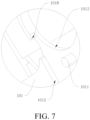
- FIG. 7 is an enlarged view at C in FIG. 6 .
- a plurality of bus bars 102 and grooves 1012 are provided, and the plurality of bus bars 102 and the plurality of grooves 1012 are arranged in one-to-one correspondence.
- the first insulating bracket 101 is provided with a first flow glue groove (1018) arranged between adjacent two of the plurality of grooves 1012. The adjacent two of the plurality of grooves (1012) are communicated through the first flow glue groove 1018.
- the glue flows into one groove 1012, and flows through the first flow glue grooves 1018 into another grooves 1012 communication with the first flow glue grooves 108, so that the glue may fill all of the grooves 1012.
- the first glue flow grooves 1018 communication with each other are provided respectively between the two adjacent grooves 1012, so that the flowable path of the glue may be increased in the glue injection operation.
- the glue injection efficiency may be improved, and the glue filling may be made more uniform.
- the bus bar 102 is clearance-fitted with the groove 1012.
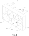
- FIG. 8 is a schematic structural view of the CCS assembly from another perspective provided by some embodiments of the present disclosure.
- the first insulating bracket 101 is provided with a plurality of mounting grooves 1017 configured to mount cells.
- a plurality of second glue flow grooves 1019 are provided, and each of the plurality of the second glue flow grooves 1019 is provided between two adjacent mounting grooves 1017 on the first insulating bracket 101, and two adjacent mounting grooves 1017 communicate with each other through one second glue flow groove 1019.
- the mounting groove 1017 may be a cylindrical groove.
- the cells are mounted and positioned by the mounting grooves 1017.
- the layout neatness of the cells may be improved, which facilitates subsequent welding between the cells and the bus bar 102.
- the assembly efficiency may be improved.
- the glue may flow between two adjacent mounting grooves 1017 through the second glue flow groove 1019, so that the flowable path of the glue may be increased during the glue injection operation.
- the glue injection efficiency may be improved, and the glue filling may be made more uniform.
- the positive electrode of the cylindrical cell in condition that the plurality of bus bars 102 are series bus bars, is connected to one bus bar 102, and the negative electrode of the cell is connected to the other bus bar 102.
- the positive electrode and the negative electrode of the cell are located at the same end of the cell, and the negative electrode is arranged around the positive electrode.
- one end of the bus bar 102 is provided with an outer convex portion having a cylindrical arc-shaped structure, and the other end is provided with an inner concave portion having a cylindrical arc-shaped structure.
- One end of the bus bar 102 close to the outer convex portion is electrically connected to the positive electrode of the cell, and one end close to the inner concave portion is electrically connected to the negative electrode of the cell.
- the outer convex portion of one bus bar 102 faces the inner concave portion of the other bus bar 102 along the series connection direction of the cells. Therefore, the positive and negative electrode arrangement structure of the cells may be adapted to meet the spacing requirements between the two bus bars 102 connected to the same cell, and the contact area between the bus bar 102 and the electrodes of the cells may be larger.
- the outer convex portion of one bus bar 102 is concentrically provided with the inner concave portion of the other bus bar 102 along the series connection direction of the cells.
- the outer convex portion and the inner concave portion of the bus bar 102 are coaxial with the cell connected to the bus bar 102.
- the FPC board 103 includes a body part 1031 and a plurality of feet 1032 connected to the body part 1031.
- the body part 1031 is connected to the BMS board.
- the feet 1032 are connected to the bus bars 102.
- the FPC board 103 is embedded in the first insulating bracket 101.
- a plurality of feet 1032 are also provided.
- the feet 1032 are arranged in one-to-one correspondence with the bus bars 102, and the feet 1032 are connected to the bus bars 102, respectively.
- the FPC board 103 is connected to the bus bars 102 through the plurality of feet 1032, so that the portions where the FPC board 103 is connected to the bus bars 102 may have better flexibility.
- the flatness of the portions where the FPC board 103 is connected to the bus bars 102 may be improved.
- the stability of contact between the portions where the FPC board 103 is connected to the bus bars 102 and the bus bars 102 may be improved, thereby facilitating signal acquisition.
- the bus bar 102 configured to connect cells in series includes a bent portion 1022.
- One side of the bent portion 1022 is in contact with the positive electrode of the cell, and the other side of the bent portion 1022 is in contact with the negative electrode of the cell.
- both ends of the bus bar 102 may be brought into contact with the positive electrode of the cell and the negative electrode having a height lower than the positive electrode, respectively, without increasing the thickness of the bus bar 102.
- the thickness of the bus bar 102 may be controlled, and the material of the bus bar 102 may be reduced.
- FIG. 9 is a bottom view of the CCS assembly provided by some embodiments of the present disclosure.
- the first insulating bracket 101 includes a first surface and a second surface opposite to each other.
- the first surface is provided with a plurality of mounting grooves 1017 configured to mount the cells.
- the second surface is provided with the grooves 1012 configured to mount the bus bars 102, and each of the grooves is located between two adjacent mounting grooves 1017.
- One end of the groove bottom of the groove 1012 communicates with an adjacent mounting groove 1017 through a second through hole 1013.
- the other end of the groove bottom of the groove 1012 communicates with the other adjacent mounting groove 1017 through a third through hole 1014.
- one end of the bus bar 102 in the groove 1012 is electrically connected to the positive electrode of one cell through the second through hole 1013.
- the other end of the bus bar is electrically connected to the negative electrode of the other cell through the third through hole 1014.
- the first surface of the first insulating bracket 101 is provided with a main groove.
- a plurality of cylinders 1016 are provided in the main groove.
- the circumferential surfaces of two adjacent cylinders 1016 communicate with each other along the series connection direction of the cells.
- the barrel cavity of the cylinder 1016 forms the mounting groove 1017.
- a plurality of cylinders 1016 are provided and are divided into two groups.
- the plurality of cylinders 1016 in each group are arranged at intervals along a first direction, and the cylinders 1016 in the two groups are arranged staggered with each other.
- a circumferential surface of one of the cylinders 1016 in one group communicates with circumferential surfaces of two cylinders 1016 adjacent thereto in the other group. In this way, the mounting grooves 1017 for mounting the cells may be formed, the material consumption of the first insulating bracket 101 may be reduced, and the material cost may be reduced.
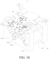
- FIG. 10 is a schematic structural view of the battery module provided by some embodiments of the present disclosure.
- the battery module 1 provided by the embodiments of the present disclosure includes a second insulating bracket 40, a cell 20, a BMS board 30, and a CCS assembly 10.
- the second insulating bracket 40 is disposed opposite to the first insulating bracket 101.
- the cell 20 is disposed between the first insulating bracket 101 and the second insulating bracket 40.
- the cell 20 is connected to the bus bars 102.
- the BMS board 30 is connected to the FPC board 103.
- the second insulating bracket 40 is a plastic bracket like the first insulating bracket 101.
- a plurality of cells 20 may be provided, and correspondingly, a plurality of bus bars 102 are also provided.
- Part of the bus bars 102 may be a series bus bar that connects the cells 20 in series into a cell group.
- the other part of the bus bar 102 may be a positive output bus bar that connects the positive output terminal of the cell group with the positive output bit of the BMS board 30, or may be a negative output bus bar that connects the negative output terminal of the cell group with the negative output bit of the BMS board 30.
- the BMS board 30A is provided with a positive electrode lead-out terminal connected to the positive electrode output bit and a negative electrode lead-out terminal connected to the negative electrode output bit.
- the BMS board 30 is connected to other battery modules or electrical device through the positive electrode lead-out terminal and the negative electrode lead-out terminal.
- the first insulating bracket 101 and the second insulating bracket 40 are located at both ends of the cells 20 respectively.
- the cells 20 are fixed between the first insulating bracket 101 and the second insulating bracket 40 to improve the positional stability of the cells 20.
- the output terminal of the FPC board 103 is soldered to the acquisition board of the BMS board 30.
- Four cells 20 are provided, and the four cells 20 are cylindrical cells.
- the voltage amplitude of each cylindrical cell is 3 V
- the voltage amplitude of the battery module 1 is 12 V Compared with the square cell, there is no need for the cylindrical cell to configure a square end plate for installing the cell 20. The process may be simplified and the material cost may be reduced.
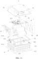
- FIG. 11 is an explosion view of the battery provided by some embodiments of the present disclosure.
- the battery provided by the embodiments of the present disclosure includes a box and a battery module 1.
- the box is provided with an accommodation cavity.
- the battery module 1 is accommodated in the accommodation cavity.
- FIG. 13 is a schematic structural view of the box body 41 provided by the embodiments of the present disclosure
- FIG. 14 is a top view of the box body 41 provided by the embodiments of the present disclosure.
- One groove end of the guide groove 4111 faces the end plate 412, and the other groove end of the guide groove 4111 faces an opening of the accommodation cavity 46.
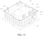
- FIG. 15 is a schematic view of cooperation between the box body 41 and the battery module 1 provided by some embodiments of the present disclosure.
- One end of the first insulating bracket 101 is inserted into the guide groove 4111 and connected to a wall surface of the guide groove 4111.
- the box cap 42 covers a side of the annular structure facing away from the end plate 412, thereby isolating the accommodation cavity 46 from the outside.
- One end of the first insulating bracket 101 is inserted into the guide groove 4111 and connected to a wall surface of the guide groove 4111, and/or one end of the second insulating bracket 40 is inserted into the guide groove 4111 and connected to the wall surface of the guide groove 4111.
- one end of the first insulating bracket 101 may be inserted into the guide groove 4111 and connected to the wall surface of the guide groove 4111.
- One end of the second insulating bracket 40 may be inserted into the guide groove 4111 and connected to the wall surface of the guide groove 4111.
- One end of the first insulating bracket 101 may be inserted into the guide groove 4111 and connected to the wall surface of the guide groove 4111, and one end of the second insulating bracket 40 may be inserted into the guide groove 4111 and connected to the wall surface of the guide groove 4111.
- the box 4 is made of an aluminum alloy material.
- a crisscross shaped reinforcing rib 413 is provided both on the outer wall of the enclosure plate 411 and a side of the end plate 412 close to the accommodation cavity 46, so that the structural strength of the box body 41 may be greatly improved, and the safety of the battery may be improved.
- the first insulating bracket 101 or the second insulating bracket 40 fitted to the guide groove 4111 may be bonded to the wall surface of the guide groove 4111 by glue, or may be bonded to the guide groove 4111 by hot melt.
- the battery module 1 may include four cylindrical cells 20 connected in series, and the voltage of each cell 20 is 3 V Correspondingly, the voltage of the battery module 1 is 12 V
- FIG. 16 is an enlarged view at D in FIG. 14 .
- a pair of positioning plates 4112 are provided on a side of the enclosure plate 411 close to the accommodation cavity 46. A gap between the pair of positioning plates 4112 forms the guide groove 4111.
- one of the plurality of enclosure plates is provided with one or two pairs of positioning plates 4112, or opposite two of the plurality of enclosure plates are provided with respective one or two pairs of positioning plates 4112.
- the enclosure plates 411 and the positioning plates 4112 are integrally formed structures and are metal parts.
- the guide groove 4111 is defined by providing the positioning plate 4112, so that the overall structure of the box 4 is simple and manufactured conveniently.
- the guide groove 4111 may be defined by the enclosure plate 411.
- the guide groove 4111 is formed by providing the positioning plate 4112, which has no influence on the size of the box 4, and may effectively control the material consumption of the enclosure plate 411, thereby reducing the material cost of the box 4.
- the positioning plate 4112 includes a side surface facing away from the enclosure plate 411 on which the positioning plate 4112 is located.
- the spacing between the side surface and the enclosure plate 411 on which the positioning plate 4112 is located is L.
- the minimum distance between the enclosure plate 411 where the positioning plate 4112 is located and the cell 20 is L0.
- An end portion of the cell 20 is inserted into the second insulating bracket 40, and an end portion of the second insulating bracket 40 is inserted into the guide groove 4111, whereby the positioning plate 4112 is disposed opposite to the cell 20.
- the minimum distance L0 is the distance between the outer peripheral surface of one of the cells closest to the positioning plate 4112 and the enclosure plate 411 on which the positioning plate 4112 is located.
- the spacing L is less than or equal to L 0 is defined to avoid interference between the positioning plate 4112 and the cell 20 due to the excessively large size of the positioning plate 4112. If the spacing L is too small, it is not conducive to limiting the position of the battery module 1 by the positioning plate 4112. Therefore, that the spacing L is greater than or equal to 0.5 mm is defined.
- the thickness of the positioning plate 4112 is D, which satisfies 0.5 mm ⁇ D ⁇ 3 mm.
- the thickness D of the positioning plate 4112 is too small, the strength thereof is insufficient, and the positioning plate 4112 is easily broken. If the thickness D of the positioning plate 4112 is too large, it will lead to unnecessary waste of materials. Therefore, the thickness D of the positioning plate 4112 is limited above, so that the positioning plate 4112 is not easily damaged during assembly and use, and the amount of materials may be controlled to avoid waste of materials.
- the thickness D may be 2 mm or 2.4 mm.
- the guide grooves 4111 are provided on the two oppositely disposed enclosure plates 411, and the guide grooves 4111 on the two enclosure plates 411 are oppositely disposed. Both ends of the first insulating bracket 101 are inserted into the two guide grooves, respectively, or both ends of the second insulating bracket 40 are inserted into the two guide grooves, respectively.
- both ends of the first insulating bracket 101 or the second insulating bracket 40 are limited by the guide grooves 4111, thereby improving the stability of the installation of the battery module 1 and the accuracy of the position.
- two guide grooves 4111 are both provided on two oppositely disposed enclosure plates 411, and the guide grooves 4111 on the two enclosure plates 411 are provided oppositely in one-to-one correspondence. Both ends of the first insulating bracket 101 are inserted into two guide grooves, respectively, and both ends of the second insulating bracket 40 are inserted into the other two guide grooves, respectively.
- both ends of the first insulating bracket 101 are inserted into a pair of opposite guide grooves 4111, and both ends of the second insulating bracket 40 are inserted into the other pair of opposite guide grooves 4111.
- both the first insulating bracket 101 and the second insulating bracket 40 of the battery module 1 are limited by the guide grooves 4111, thereby improving the stability of the installation of the battery module 1 and the accuracy of the position.
- one end of one of the plurality of the enclosure plates 411 facing the accommodating cavity 46 and away from the end plate 412 is provided with an output pole fixing base 414, and a side of the output pole fixing base 414 facing away from the end plate 412 is provided with a threaded hole 4141.
- the battery module 1 further includes a BMS board 30.
- One end of the CCS assembly 10 is connected to the cells 20, and the other end of the CCS assembly 10 is connected to the BMS board 30.
- the BMS board 30 is connected to an external load through a positive lead-out terminal and a negative lead-out terminal.
- the threaded hole 4141 is engaged with a screw. The screw end of the screw is connected to the threaded hole 4141 after passing through a metal row connected between the CCS assembly 10 and the BMS plate 30, and then the metal row is fixed between the output pole fixing base 414 and the head of the screw.
- the BMS board 30 is a battery management system. As a control unit of the battery, the BMS board 30 may realize functions such as voltage acquisition and temperature acquisition for the cell 20, and charge and discharge control and equalization for the battery module 1.
- the CCS assembly 10 is an acquisition integrated component of the battery module 1, and connects the collected operation information of the cells and the positive and negative output terminals of the cells to the BMS board. After mounted on the second insulating bracket 40, the cells 20 are welded to the CCS module 10. After welding, the battery module 1 is loaded into the box 4. A surface of the metal row in contact with the output pole fixing base 414 and the screw is provided with an insulating structure.
- the insulating structure may be an insulating layer formed by spraying or dipping plastic, or may be a heat-shrinkable tube, which is sleeved on the metal row to form an insulating structure.
- the reliability and safety of the electrical connection of the battery may be improved.
- the structure is simple, which is beneficial to realizing the function of quick assembly.
- the guide groove 4111 is glued to one of the first insulating bracket 101 and the second insulating bracket 40.
- the battery module 1 when the battery module 1 is mounted into the box 4, it is only necessary to apply the structural adhesive to the portion of one of the first bracket 101 and the second insulating bracket 40 that fits with the guide groove 4111, and/or apply the structural adhesive to the guide groove 4111 after the assembly of the battery module 1 is completed. Then, the battery module 1 is slid into the accommodation cavity 46 along the guide groove 4111, so that one of the first insulating bracket 101 and the second insulating bracket 40 that mates with the guide groove 4111 is cemented with the guide groove 4111 by the structural adhesive. As a result, the installation of the battery module 1 is completed.
- the installation method is simple and efficient, so that the industrialization process of the battery is greatly simplified, and the production efficiency is greatly improved.
- the matching of the battery module 1 and the guide groove 4111 may improve the positioning accuracy of the battery module 1, thereby improving the assembly accuracy of the battery.
- the guide groove 4111 is gap-fitted with one of the first insulating bracket 101 and the second insulating bracket 40 to form a gap configured to store glue.
- one of the first insulating bracket 101 or the second insulating bracket 40 that fits with the guide groove 4111 is gap-fitted with the guide groove 4111 to form the gap for storing glue.
- the gap is configured to be filled with glue or hot melt material.
- the width dimension of the guide groove 4111 is L1
- the dimension of one of the first insulation bracket 101 and the second insulation bracket 40 that fits with the guide groove 4111 along the width direction of the guide groove 4111 is L2, satisfying: L1>L2.
- the fitting clearance between the second insulating bracket 40 and the guide groove 4111 ranges from 0.2 mm to 1.1 mm.
- the fitting clearance ranges from 0.3 mm to 1 mm, specifically 0.5 mm.
- one of the first insulating brackets 101 and the second insulating brackets 40 that mates with the guide groove 4111 may be fastened to the guide groove 4111 by an interference fit with the guide groove 4111.
- the slot port of the guide groove 4111 facing the opening of the accommodation cavity 46 may be enlarged, or the size of one end of one of the first insulating brackets 101 and the second insulating brackets 40 that mates with the guide groove 4111 facing the bottom wall of the accommodation cavity 46 may be reduced. Both the enlargement and reduction may be achieved by rounding the corners at the corresponding locations.
- one end of the groove wall of the guide groove 4111 facing the opening of the accommodation cavity 46 may be provided with a chamfer, and the chamfer may be a rounded corner or a chamfered corner.
- One end of the side surface of one of the first insulating brackets 101 and the second insulating brackets 40 that fits with the guide groove 4111 facing the groove wall of the guide groove 4111 and close to the bottom wall of the accommodation cavity 46 may be provided with a chamfer.
- the chamfer may be a rounded corner or a chamfered corner.
- the fit between the first insulating bracket 101 or the second insulating bracket 40 and the box is changed from a clearance fit to a transition fit and then to an interference fit, so that the battery module 1 is fixed in the guide groove 4111 by the squeezing force generated by the interference fit.
- the box cap 42 is provided with a handle 43.
- the handle 43 is rotatably connected to the box cap 42.
- a side of the box cap 42 facing away from the box body 41 is provided with a avoidance groove 421.
- the handle 43 is positioned in the leaving groove 421 by rotation. In this way, the convenience of transportation of the battery may be improved by the handle 43, and the battery may be directly fitted into the box cap when the handle 43 is not used, so that excess space is not occupied.
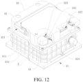
- FIG. 17 is an enlarged view at E in FIG. 12
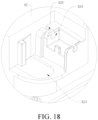
- FIG. 18 is a schematic structural view of FIG. 17 after a protective cover 44 is removed.
- Two output pole interfaces 423 may be provided, which are a positive output pole interface and a negative output pole interface, respectively.
- the output pole of the positive lead-out terminal is arranged through the positive output pole interface.
- the negative lead-out terminal is arranged through the negative output pole interface.
- the protective cover 44 is provided on the box cap 42 close to the output pole interfaces 423.
- the protective cover 44 is hinged with the box cap 42.
- the protective cover 44 is configured to cover or expose the output pole.
- the protective cover 44 is configured to protect the output poles, thereby improving the electrical safety of the battery.
- the output pole connects the battery to the vehicle, which is directly connected to the corresponding interface of the vehicle.
- the low voltage interface 422 is configured for a wiring harness passing through, and the wiring harness connects the BMS board 30 and the controller of the whole vehicle, so that the communication between the BMS board 30 and the controller may be achieved, thereby facilitating the BMS board 30 to send and receive instructions and the like.
- the box cap 42 is provided with a mounting hole 424, a hole wall of the mounting hole 424 communicates with the outside through a notch 425, and the central angle of the notch 425 is less than 90 °.
- One side of the protective cover 44 is provided with an articulation shaft 441 whose diameter is larger than the width dimension of the notch 425. The articulation shaft 441 is positioned in the mounting hole 424 and interference fitted with the mounting hole 424.
- the mounting hole 424 is circular in cross-section.
- the protective cover 44 covers or exposes the output poles by rotating about the axis of the mounting hole 424.
- the articulation shaft 441 may be withdrawn from or externally fitted into the mounting hole 424 by squeezing the notch 425.
- the articulation shaft 441 is interference fitted with the mounting hole 424, so that the protective cover 44 may stably covers the poles, and the pole may be avoided from being arbitrarily exposed.
- a gasket 45 is provided between the box cap 42 and the box body 41.
- the gasket 45 is pressed against the box body 41 by the box cap 42 to improve the sealing property of the accommodation cavity 46.
- the electrical device provided by the embodiments of the present disclosure includes the battery 2, and the battery 2 provides electrical energy to the electrical device.
- the electrical device for convenience of explanation, taking the electrical device as a vehicle 3 as an example for description.
- FIG. 19 is a schematic structural view of the vehicle 3 provided by some embodiments of the present disclosure.
- the vehicle 3 may be a fuel vehicle, a gas vehicle, or a new energy vehicle.
- the new energy vehicle may be a pure electric vehicle, a hybrid vehicle, an extended-range vehicle, or the like.
- the battery 2 is provided inside the vehicle 3, and the battery 2 may be provided at the bottom, head or rear of the vehicle 3.
- the battery 2 may supply power to the vehicle 3, for example, the battery 2 may serve as an operating power source for the vehicle 3.
- the vehicle 3 may further include a controller 31, while the vehicle 3 may further include an engine 32.
- the battery 2 supplies power to the controller 31 and the engine 32, for example, to meet the operational power requirements of the vehicle 3 during start-up, navigation, and driving.
- the battery 2 may not only serve as the operating power source of the vehicle 3, but also serve as a driving power source of the vehicle 3 to provide driving power for the vehicle 3 instead of or partially instead of fuel oil or natural gas.
Landscapes
- Chemical & Material Sciences (AREA)
- Chemical Kinetics & Catalysis (AREA)
- Electrochemistry (AREA)
- General Chemical & Material Sciences (AREA)
- Engineering & Computer Science (AREA)
- Aviation & Aerospace Engineering (AREA)
- Battery Mounting, Suspending (AREA)
- Connection Of Batteries Or Terminals (AREA)
Abstract
Description
- The present disclosure relates to the technical field of batteries, in particular to a cells contact system (CCS) assembly, a battery module, a battery and an electrical device.
- In the related art, operating signals of a battery module are collected by a CCS assembly. The CCS assembly includes a plastic bracket and an output bus bar, a series bus bar and a flexible printed circuit (FPC) board mounted on the plastic bracket. The FPC board is electrically connected to the output bus bar, the series bus bar, and a battery management system (BMS) board. In the related art, a plurality of cells are mounted on the plastic bracket. The bus bar is arranged on one side of the plastic bracket and welded with the poles of the cells.
- When the bus bar is mounted on the plastic bracket, the positional accuracy of the bus bar is poor, resulting in low alignment accuracy between the bus bar and the poles of the cells. The low alignment accuracy leads to poor welding reliability between the bus bar and the poles of the cells.
- Embodiments of the present disclosure provide a CCS assembly, a battery module, a battery and an electrical device, which may improve the positional accuracy of a bus bar. The alignment accuracy of the bus bar and poles of a plurality of cells may be improved. Poor welding reliability between the bus bar and the poles of the cells may be improved.
- In a first aspect, the CCS assembly provided by the present disclosure includes a first insulating bracket, at least a bus bar, and an FPC. A first insulating bracket is configured to mount a plurality of cells and is provided with at least a positioning post. The bus bar is configured to be connected to the cells. The bus bar is arranged on the first insulating bracket and is provided with a first through hole. The bus bar is sleeved on the positioning post through the first through hole. The FPC board is connected to the bus bar and is configured to transmit operating signals of the bus bar to the BMS board.
- In a second aspect, the battery module provided by the present disclosure includes a second insulating bracket, a plurality of cells, a battery management system (BMS), and the above CCS assembly. The second insulating bracket is disposed opposite to the first insulating bracket. The cells are arranged between the first insulating bracket and the second insulating bracket. The cells are connected to the bus bar. The BMS board is connected to the FPC board.
- In a third aspect, the battery provided by the present disclosure includes a box and the above battery module. The box is provided with an accommodation cavity. The battery module is accommodated in the accommodation cavity.
- In a fourth aspect, the electrical device provided by the present disclosure includes the above battery, and the battery is configured to supply electrical energy to the electrical device.
- In the present disclosure, by providing a positioning post and sleeving the bus bar on the positioning post, the bus bar is positioned according to the positioning post. The positional accuracy of the bus bar mounted on the first insulating bracket is improved, and the alignment accuracy of the bus bar and poles of the cells mounted on the first insulating bracket is improved. Poor welding reliability between the bus bar and the poles of the cells is improved.
-
-
FIG. 1 is a schematic structural view of a CCS assembly provided by some embodiments of the present disclosure. -
FIG. 2 is a top view of a CCS assembly provided by some embodiments of the present disclosure. -
FIG. 3 is a cross-sectional view along a line A-A ofFIG. 2 . -
FIG. 4 is an enlarged view at B inFIG. 3 . -
FIG. 5 is a schematic structural view of a positioning post provided by some embodiments of the present disclosure after being heated. -
FIG. 6 is a schematic structural view of a first insulating bracket provided by some embodiments of the present disclosure. -
FIG. 7 is an enlarged view at C inFIG. 6 . -
FIG. 8 is a schematic structural view of the CCS assembly from another perspective provided by some embodiments of the present disclosure. -
FIG. 9 is a bottom view of the CCS assembly provided by some embodiments of the present disclosure. -
FIG. 10 is a schematic structural view of a battery module provided by some embodiments of the present disclosure. -
FIG. 11 is an explosion view of a battery provided by some embodiments of the present disclosure. -
FIG. 12 is a schematic structural view of a box provided by some embodiments of the present disclosure. -
FIG. 13 is a schematic structural view of a box body provided by some embodiments of the present disclosure. -
FIG. 14 is a top view of the box body provided by some embodiments of the present disclosure. -
FIG. 15 is a schematic view of cooperation between the box body and the battery module provided by some embodiments of the present disclosure. -
FIG. 16 is an enlarged view at D inFIG. 14 . -
FIG. 17 is an enlarged view at E inFIG. 12 . -
FIG. 18 is a schematic view of the structure inFIG. 17 after the protective cap is removed. -
FIG. 19 is a schematic structural view of a vehicle provided by some embodiments of the present disclosure. -
- 1, battery module;
- 10, CCS assembly; 20, cell; 30, BMS plate; 40, second insulating bracket;
- 101, first insulating bracket; 1011, positioning post; 1012, groove; 1013, second through hole; 1014, third through hole; 1015, body groove; 1016, cylinder; 1017, mounting groove; 1018, first flow glue groove; 1019, second flow glue groove;
- 102, bus bar; 1021, first through hole; 1022, bent part;
- 103, FPC board; 1031 body part; 1032, foot;
- 2, battery;
- 3, vehicle; 31, controller; 32, engine;
- 4, box;
- 41, box body; 42, box cap; 421, avoidance groove; 422, low voltage interface; 423, output pole interface; 424, mounting hole; 425, notch; 43, carrying handle; 44, protective cap; 441, articulation shaft; 45, gasket; 46, accommodation cavity;
- 411, enclosure plate; 4111, guide groove; 4112, positioning plate; 412, end plate; 413, stiffener; 414, output pole fixing base; 4141, threaded hole.
- In the related art, the plastic bracket on which the cells are mounted may not position the bus bar, which leads to low accuracy of the installation position of the bus bar, resulting in low alignment accuracy between the bus bar and the poles of the cells. The low alignment accuracy leads to poor welding reliability between the bus bar and the poles of the cells.
- Based on the above circumstances, the embodiments of the present disclosure provide a CCS assembly, a battery module, a battery, and an electrical device. The electrical device may be electric toys, electric tools, electromobiles, automobiles, ships, spacecraft, etc. The automobile may be a fuel vehicle, a hybrid vehicle or a pure electric vehicle, etc.
- An FPC board in the embodiments of the present disclosure refers to a flexible printed circuit board, also referred to as a flexible or soft circuit board. It is a circuit board made using a flexible substrate that may be bent and folded in three dimensions to accommodate a variety of applications with special shapes and space constraints. The FPC board has the characteristics of small size, light weight and high reliability, and is commonly used in mobile devices, automotive electronics, armamentarium and aerospace.
- The BMS board in the embodiments of the present disclosure refers to a battery management system board, also referred to as a battery management board. It is an electronic device used to monitor, control and protect a battery pack. The BMS board may include components such as a battery monitoring unit, a protection unit, and communication interfaces. The main functions of the BMS board include measuring the voltage, current and temperature of the battery, implementing charge and discharge control, monitoring the battery status and identifying faults to ensure the stable operation and safety of the battery. The BMS board is widely used in electric vehicles, energy storage systems, portable devices and other fields that require the use of batteries.
- The CCS assembly, the battery module, the battery, and the electrical device provided by the embodiments of the present disclosure will be described in detail below, respectively.
- Referring to
FIGs. 1 to 4 ,FIG. 1 is a schematic structural view of theCCS assembly 10 provided by some embodiments of the present disclosure.FIG. 2 is a top view of the CCS provided by some embodiments of the present disclosure.FIG. 3 is a cross-sectional view taken along A-A inFIG. 2 .FIG. 4 is an enlarged view at B inFIG. 3 . TheCCS assembly 10 provided by the embodiments of the present disclosure includes a firstinsulating bracket 101, abus bar 102, and anFPC board 103. The firstinsulating bracket 101 is configured to mount a plurality of cells. The firstinsulating bracket 101 includes apositioning post 1011. Thebus bar 102 is configured to be connected to the cells. Thebus bar 102 is provided on the first insulatingbracket 101. Thebus bar 102 is provided with a first throughhole 1021. Thebus bar 102 is sleeved on thepositioning post 1011 through the first throughhole 1021. TheFPC board 103 is connected to thebus bar 102 and is configured to transmit operation signals of thebus bar 102 to the BMS board. - For example, the first insulating
bracket 101 may be a plastic bracket, which is injection molded. Thepositioning post 1011 is integrally molded with the first insulatingbracket 101. As an insulating member, the first insulatingbracket 101 may insulate non-welded regions between thebus bar 102 and the cells, thereby ensuring insulation performance in accordance with electrical safety standards. TheFPC board 103 and thebus bar 102 are integrated into one piece, so that the integrated feeding of theFPC board 103 and thebus bar 102 may be realized in the assembly of theCCS assembly 10, thereby facilitating the efficient execution of related production operations. - It can be understood that the
bus bar 102 may be a series bus bar, an output bus bar, or both. The series bus bar connects a plurality of cells in series. The output bus bar connects series-connected cell groups in parallel, or connects the series-connected cell group with other loads. Thebus bar 102 is a metal bar, and may be, for example, a copper bar, an aluminum bar, or the like. Thebus bar 102 is electrically connected to electrodes of the cells, thereby transmitting the electric energy of the cells. TheFPC board 103 mainly collects the voltage signal and the temperature signal of the battery module. An input terminal of theFPC board 103 is electrically connected to thebus bar 102, and an output terminal of theFPC board 103 may be directly welded to an acquisition board of the BMS board. TheFPC board 103 collects the voltage signal of each cell, and transmits the collected voltage signal to the BMS board. - In the embodiments, by providing the
positioning post 1011 and sleeving thebus bar 102 on thepositioning post 1011, thebus bar 102 may be positioned according to thepositioning post 1011. The positional accuracy of thebus bar 102 mounted on the first insulatingbracket 101 may be improved, and the alignment accuracy of thebus bar 102 and poles of the cells mounted on the first insulatingbracket 101 is improved. Poor welding reliability between thebus bar 102 and the poles of the cells may be improved. - Further, the cells may be mounted on the first insulating
bracket 101 of theCCS assembly 10 supporting the respective electrical connection components. In this way, when assembling the battery module, it is not necessary to separately configure the bracket for carrying the electrical connection components and the bracket for carrying the cell, so that the structure of thebattery module 1 using theCCS module 10 may be simpler, and then the related assembly process may be simplified. As a result, not only the production efficiency may be improved, but also the production cost may be reduced, thereby improving the cost performance of related products. - Specifically, the first insulating
bracket 101 includes a first surface and a second surface opposite to each other. The first surface is provided with a plurality of mountinggrooves 1017 configured to mount the cells. The second surface is provided with thepositioning post 1011 located between two adjacent mountinggrooves 1017. One end of the groove bottom of the mountinggroove 1017 communicates with the second surface through a second throughhole 1013, and the second throughhole 1013 is provided opposite to one end of thebus bar 102. The other end of the groove bottom of the mountinggroove 1017 communicates with the second surface through a third throughhole 1014, and the third throughhole 1014 is provided opposite to the other end of thebus bar 102. It can be understood that one end of thebus bar 102 is electrically connected to a positive electrode of the cell located in one mountinggroove 1017 through the second throughhole 1013. The other end of thebus bar 102 is electrically connected to a positive electrode of the cell located in the other mountinggroove 1017 through the third throughhole 1014. - It can be understood that when a plurality of cells in the battery module are provided, it is necessary to configure a plurality of
bus bars 102 as a series bus bar to connect the plurality of cells in series. As shown inFIGs. 1 and2 , there are a plurality ofbus bars 102 and a plurality ofpositioning posts 1011, and the bus bars 102 and the plurality ofpositioning posts 1011 are provided in one-to-one correspondence. - In addition, in the embodiments, the
FPC board 103 and the BMS board are directly connected. The intermediate adapter connector is omitted, which not only improves the reliability of the connection between theFPC board 103 and the BMS board, facilitates signal transmission, but also reduces the material cost. - Referring to
FIG. 5, FIG. 5 is a schematic structural view of thepositioning post 1011 provided by some embodiments of the present disclosure after being heated. In some embodiments, thepositioning post 1011 is a hot-riveted post and is hot-riveted connected to thebus bar 102. - It can be understood that the
positioning post 1011 is a plastic piece that will become a viscous fluid by heating and returns to a solid state as the temperature decreases. The hot-riveted connection is that the positioning post is heated by the heat riveting machine to melt and adhere to thebus bar 102, and is connected to thebus bar 102 after curing, so that thebus bar 102 is fixed on thefirst insulation bracket 101. - In some embodiments, by providing the
positioning post 1011 as a hot-riveted post, after thebus bar 102 is sleeved on thepositioning post 1011, thepositioning post 1011 is heated so that thepositioning post 1011 is at least partially melted and bonded to thebus bar 102. Thebus bar 102 may be fixed on the first insulatingbracket 101. The fixing structure is simple, and the fixing method is convenient. The installation efficiency may be improved, and the manufacturing cost may be reduced. - In addition, the hot-riveted post is used to fix the
bus bar 102, so there is no need to fix thebus bar 102 with glue, thereby effectively preventing the glue from overflowing and contaminating the CCS assembly. - Referring to
FIGs. 3 and4 , in some embodiments, one end of thepositioning post 1011 facing away from the first insulatingbracket 101 passes through thebus bar 102. - In the embodiments, by providing one end of the
positioning post 1011 passing through thebus bar 102, the convenience of heating and melting thepositioning post 1011 may be improved, and the amount of material melted from thepositioning post 1011 may be increased. The area of the connection between thepositioning post 1011 and thebus bar 102 may be increased, so that the connection stability between thebus bar 102 and the first insulatingbracket 101 may be improved. - Referring to
FIG. 4 , in some embodiments, a length of the end of thepositioning post 1011 passing through thebus bar 102 is L, which satisfies 0.5 mm ≤ L ≤ 5 mm. - In the embodiments, with L within the above range, the
positioning post 1011 may be heated and melted more conveniently, and an appropriate amount of material melted from thepositioning post 1011 may be obtained for connecting the first insulatingbracket 101, so as to control the material cost of thepositioning post 1011. Specifically, 0.2 mm ≤ L ≤ 4 mm. Exemplarily, L is equal to 2.4 mm. - One end of the
positioning post 1011 facing away from the first insulatingbracket 101 is heated. After melted, the end of thepositioning post 1011 facing away from the first insulatingbracket 101 is pressed by an indenter, so that the heated and melted part of thepositioning post 1011 collapses toward thebus bar 102. The area of the connection surface between thebus bar 102 and thepositioning post 1011 may be increased. - Referring to
FIG. 2 , in some embodiments, thepositioning post 1011 is a cylinder. - It can be understood that the first through
hole 1021 in thebus bar 102 that mates with thepositioning post 1011 is a circular hole. - In the embodiments, by providing the
positioning post 1011 as the cylinder, when thebus bar 102 is installed, the contact area between thebus bar 102 and thepositioning post 1011 may be increased, and the positioning accuracy of thebus bar 102 may be improved. In addition, by providing thecylindrical positioning post 1011 mating with the circular hole, the tolerance of theCCS assembly 10 for relative deviation between thepositioning post 1011 and the first throughhole 1021 may be increased, so that thebus bar 102 may be more smoothly installed on the first insulatingbracket 101. - Referring to
FIG. 4 , in some embodiments, the locatingpost 1011 is clearance-fitted with thebus bar 102. - Exemplarily, the fitting clearance between the
positioning post 1011 and the first throughhole 1021 ranges from 0.1 mm to 0.6 mm, for example, 0.4 mm. For example, a diameter of thepositioning post 1011 is 3 mm. A diameter of the first throughhole 1021 is 3.4 mm. - In the embodiments, the
positioning post 1011 is provided in a clearance-fitted structure with thebus bar 102, so that after thepositioning post 1011 is heated and melted, the melted part of thepositioning post 1011 flows along the surface of thebus bar 102, and the other part flows along the gap between thepositioning post 1011 and thebus bar 102. Thepositioning post 1011 and thebus bar 102 may be connected in the gap, and the area of the connection surface between thepositioning post 1011 and thebus bar 102 may be increased. - Referring to
FIG. 6, FIG. 6 is a schematic structural view of the first insulating bracket provided by some embodiments of the present disclosure. In some embodiments, the first insulatingbracket 101 is provided with agroove 1012, and the bus bars 102 is embedded in thegroove 1012. As shown inFIG. 1 , thepositioning post 1011 is provided at the bottom of thegroove 1012. - In some embodiments, by embedding the
bus bar 102 into thegroove 1012, the peripheral edge of thebus bar 102 may be limited by the peripheral edge of thegroove 1012, thereby improving the mounting position accuracy of thebus bar 102. - Referring to
FIG. 7, FIG. 7 is an enlarged view at C inFIG. 6 . A plurality ofbus bars 102 andgrooves 1012 are provided, and the plurality ofbus bars 102 and the plurality ofgrooves 1012 are arranged in one-to-one correspondence. The firstinsulating bracket 101 is provided with a first flow glue groove (1018) arranged between adjacent two of the plurality ofgrooves 1012. The adjacent two of the plurality of grooves (1012) are communicated through the firstflow glue groove 1018. - It can be understood that when the battery module is glued to connect the cell and the cell holder into one piece, the glue flows into one
groove 1012, and flows through the firstflow glue grooves 1018 into anothergrooves 1012 communication with the first flow glue grooves 108, so that the glue may fill all of thegrooves 1012. - In the embodiments, the first
glue flow grooves 1018 communication with each other are provided respectively between the twoadjacent grooves 1012, so that the flowable path of the glue may be increased in the glue injection operation. The glue injection efficiency may be improved, and the glue filling may be made more uniform. - Referring to
FIG. 2 , in some embodiments, thebus bar 102 is clearance-fitted with thegroove 1012. - In the embodiments, by clearance fitting between the
bus bar 102 and thegroove 1012, it is possible to effectively avoid processing errors and avoid thebus bar 102 cannot to fit into thegroove 1012, thereby improving assembly convenience. - Referring to
FIG. 8, FIG. 8 is a schematic structural view of the CCS assembly from another perspective provided by some embodiments of the present disclosure. In some embodiments, the first insulatingbracket 101 is provided with a plurality of mountinggrooves 1017 configured to mount cells. A plurality of secondglue flow grooves 1019 are provided, and each of the plurality of the secondglue flow grooves 1019 is provided between two adjacent mountinggrooves 1017 on the first insulatingbracket 101, and two adjacent mountinggrooves 1017 communicate with each other through one secondglue flow groove 1019. - It can be understood that the first insulating
bracket 101 includes a first surface and a second surface opposite to each other. The first surface is provided with the mountinggrooves 1017. The second surface is provided with thegrooves 1012. One end of thegroove 1012 communicates with one end of the groove bottom of one mountinggroove 1017 through the second throughhole 1013. The other end of thegroove 1012 communicates with one end of the groove bottom of the other mountinggroove 1017 through the third throughhole 1014. Accordingly, one end of thebus bar 102 located in thegroove 1012 may be electrically connected to the positive electrode of one cell through the second throughhole 1013. The other end of thebus bar 102 may be electrically connected to the negative electrode of the other cell through the third throughhole 1014. Therefore, the plurality of cells may be sequentially connected in series. - Further, in condition that the cell is a cylindrical cell, the mounting
groove 1017 may be a cylindrical groove. - In the embodiments, by providing the mounting
grooves 1017, the cells are mounted and positioned by the mountinggrooves 1017. The layout neatness of the cells may be improved, which facilitates subsequent welding between the cells and thebus bar 102. The assembly efficiency may be improved. - During glue injection, the glue may flow between two adjacent mounting
grooves 1017 through the secondglue flow groove 1019, so that the flowable path of the glue may be increased during the glue injection operation. The glue injection efficiency may be improved, and the glue filling may be made more uniform. - Referring to
FIG. 2 , in some embodiments, in condition that the plurality ofbus bars 102 are series bus bars, the positive electrode of the cylindrical cell is connected to onebus bar 102, and the negative electrode of the cell is connected to theother bus bar 102. The positive electrode and the negative electrode of the cell are located at the same end of the cell, and the negative electrode is arranged around the positive electrode. Based on this, one end of thebus bar 102 is provided with an outer convex portion having a cylindrical arc-shaped structure, and the other end is provided with an inner concave portion having a cylindrical arc-shaped structure. One end of thebus bar 102 close to the outer convex portion is electrically connected to the positive electrode of the cell, and one end close to the inner concave portion is electrically connected to the negative electrode of the cell. In this way, when the plurality ofbus bars 102 are arranged, the outer convex portion of onebus bar 102 faces the inner concave portion of theother bus bar 102 along the series connection direction of the cells. Therefore, the positive and negative electrode arrangement structure of the cells may be adapted to meet the spacing requirements between the twobus bars 102 connected to the same cell, and the contact area between thebus bar 102 and the electrodes of the cells may be larger. - For example, the outer convex portion of one
bus bar 102 is concentrically provided with the inner concave portion of theother bus bar 102 along the series connection direction of the cells. The outer convex portion and the inner concave portion of thebus bar 102 are coaxial with the cell connected to thebus bar 102. - Referring to
FIGs. 1 and2 , in some embodiments, theFPC board 103 includes abody part 1031 and a plurality offeet 1032 connected to thebody part 1031. Thebody part 1031 is connected to the BMS board. Thefeet 1032 are connected to the bus bars 102. - Exemplarily, the
FPC board 103 is embedded in the first insulatingbracket 101. - It can be understood that in condition that a plurality of
bus bars 102 are provided, a plurality offeet 1032 are also provided. Thefeet 1032 are arranged in one-to-one correspondence with the bus bars 102, and thefeet 1032 are connected to the bus bars 102, respectively. - In the embodiments, the
FPC board 103 is connected to the bus bars 102 through the plurality offeet 1032, so that the portions where theFPC board 103 is connected to the bus bars 102 may have better flexibility. The flatness of the portions where theFPC board 103 is connected to the bus bars 102 may be improved. The stability of contact between the portions where theFPC board 103 is connected to the bus bars 102 and the bus bars 102 may be improved, thereby facilitating signal acquisition. - Referring to
FIG. 1 , in some embodiments, thebus bar 102 configured to connect cells in series includes a bent portion 1022. One side of the bent portion 1022 is in contact with the positive electrode of the cell, and the other side of the bent portion 1022 is in contact with the negative electrode of the cell. In this way, by providing the bent portion 1022, both ends of thebus bar 102 may be brought into contact with the positive electrode of the cell and the negative electrode having a height lower than the positive electrode, respectively, without increasing the thickness of thebus bar 102. The thickness of thebus bar 102 may be controlled, and the material of thebus bar 102 may be reduced. - Referring to
FIGs. 8 and9, FIG. 9 is a bottom view of the CCS assembly provided by some embodiments of the present disclosure. In some embodiments, the first insulatingbracket 101 includes a first surface and a second surface opposite to each other. The first surface is provided with a plurality of mountinggrooves 1017 configured to mount the cells. The second surface is provided with thegrooves 1012 configured to mount the bus bars 102, and each of the grooves is located between two adjacent mountinggrooves 1017. One end of the groove bottom of thegroove 1012 communicates with anadjacent mounting groove 1017 through a second throughhole 1013. The other end of the groove bottom of thegroove 1012 communicates with the other adjacent mountinggroove 1017 through a third throughhole 1014. - It can be understood that one end of the
bus bar 102 in thegroove 1012 is electrically connected to the positive electrode of one cell through the second throughhole 1013. The other end of the bus bar is electrically connected to the negative electrode of the other cell through the third throughhole 1014. - Exemplarily, the first surface of the first insulating
bracket 101 is provided with a main groove. A plurality ofcylinders 1016 are provided in the main groove. The circumferential surfaces of twoadjacent cylinders 1016 communicate with each other along the series connection direction of the cells. The barrel cavity of thecylinder 1016 forms the mountinggroove 1017. A plurality ofcylinders 1016 are provided and are divided into two groups. The plurality ofcylinders 1016 in each group are arranged at intervals along a first direction, and thecylinders 1016 in the two groups are arranged staggered with each other. A circumferential surface of one of thecylinders 1016 in one group communicates with circumferential surfaces of twocylinders 1016 adjacent thereto in the other group. In this way, the mountinggrooves 1017 for mounting the cells may be formed, the material consumption of the first insulatingbracket 101 may be reduced, and the material cost may be reduced. - Referring to
FIG. 10, FIG. 10 is a schematic structural view of the battery module provided by some embodiments of the present disclosure. Thebattery module 1 provided by the embodiments of the present disclosure includes a second insulatingbracket 40, acell 20, aBMS board 30, and aCCS assembly 10. The second insulatingbracket 40 is disposed opposite to the first insulatingbracket 101. Thecell 20 is disposed between the first insulatingbracket 101 and the second insulatingbracket 40. Thecell 20 is connected to the bus bars 102. TheBMS board 30 is connected to theFPC board 103. - It can be understood that one end of the
cell 20 is plugged into the first insulatingbracket 101. The other end of thecell 20 is plugged into the second insulatingbracket 40. The second insulatingbracket 40 is a plastic bracket like the first insulatingbracket 101. - It can be understood that a plurality of
cells 20 may be provided, and correspondingly, a plurality ofbus bars 102 are also provided. Part of the bus bars 102 may be a series bus bar that connects thecells 20 in series into a cell group. The other part of thebus bar 102 may be a positive output bus bar that connects the positive output terminal of the cell group with the positive output bit of theBMS board 30, or may be a negative output bus bar that connects the negative output terminal of the cell group with the negative output bit of theBMS board 30. The BMS board 30A is provided with a positive electrode lead-out terminal connected to the positive electrode output bit and a negative electrode lead-out terminal connected to the negative electrode output bit. TheBMS board 30 is connected to other battery modules or electrical device through the positive electrode lead-out terminal and the negative electrode lead-out terminal. Serving as the strength basis of theentire battery module 1, the first insulatingbracket 101 and the second insulatingbracket 40 are located at both ends of thecells 20 respectively. Thecells 20 are fixed between the first insulatingbracket 101 and the second insulatingbracket 40 to improve the positional stability of thecells 20. - Exemplarily, the output terminal of the
FPC board 103 is soldered to the acquisition board of theBMS board 30. Fourcells 20 are provided, and the fourcells 20 are cylindrical cells. The voltage amplitude of each cylindrical cell is 3 V Correspondingly, the voltage amplitude of thebattery module 1 is 12 V Compared with the square cell, there is no need for the cylindrical cell to configure a square end plate for installing thecell 20. The process may be simplified and the material cost may be reduced. - Exemplarily, five
cells 20 are provided, and the fivecells 20 are cylindrical cells. The voltage amplitude of each cylindrical cell is 5 V Correspondingly, the voltage amplitude of thebattery module 1 is 20 V - In the embodiments, by providing the
positioning post 1011 and sleeving thebus bar 102 on thepositioning post 1011, thebus bar 102 may be positioned according to thepositioning post 1011. The positional accuracy of thebus bar 102 mounted on the first insulatingbracket 101 may be improved, and the alignment accuracy of thebus bar 102 and poles of the cells mounted on the first insulatingbracket 101 is improved. The working stability of thebattery module 1 may be improved. - Referring to
FIG. 11, FIG. 11 is an explosion view of the battery provided by some embodiments of the present disclosure. The battery provided by the embodiments of the present disclosure includes a box and abattery module 1. The box is provided with an accommodation cavity. Thebattery module 1 is accommodated in the accommodation cavity. - Exemplarily, the battery may be a cylindrical power battery. The power battery refers to a battery system that provides energy to electric vehicles, hybrid vehicles, and other devices that require large-capacity energy storage. Specifically, the power battery may be a lithium iron phosphate battery, a lithium ion battery, a nickel hydride battery, a sodium ion battery, and the like. The battery is used in pure electric vehicles, fuel vehicles or hybrid vehicles.
- In the embodiments, by providing the
positioning post 1011 and sleeving thebus bar 102 on thepositioning post 1011, thebus bar 102 may be positioned according to thepositioning post 1011. The positional accuracy of thebus bar 102 mounted on the first insulatingbracket 101 may be improved, and the alignment accuracy of thebus bar 102 and poles of the cells mounted on the first insulatingbracket 101 is improved. The working stability of the battery may be improved. - Referring to
FIG. 12, FIG. 12 is a schematic structural view of the box 4 provided by some embodiments of the present disclosure. The box 4 includes abox body 41 and abox cap 42. Thebox body 41 includes anend plate 412 and a plurality ofenclosure plates 411. The plurality ofenclosure plates 411 are sequentially connected end-to-end to form an annular structure. Theend plate 412 is connected to one end of the annular structure to define theaccommodation cavity 46 for mounting thebattery module 1. A side of at least one of the plurality ofenclosure plates 411 facing theaccommodation cavity 46 is provided with at least aguide groove 4111 fitting with the second insulatingbracket 40 of thebattery module 1. As shown inFIGs. 13 and14 ,FIG. 13 is a schematic structural view of thebox body 41 provided by the embodiments of the present disclosure, andFIG. 14 is a top view of thebox body 41 provided by the embodiments of the present disclosure. One groove end of theguide groove 4111 faces theend plate 412, and the other groove end of theguide groove 4111 faces an opening of theaccommodation cavity 46. As shown inFIG. 15, FIG. 15 is a schematic view of cooperation between thebox body 41 and thebattery module 1 provided by some embodiments of the present disclosure. One end of the first insulatingbracket 101 is inserted into theguide groove 4111 and connected to a wall surface of theguide groove 4111. Thebox cap 42 covers a side of the annular structure facing away from theend plate 412, thereby isolating theaccommodation cavity 46 from the outside. - One end of the first insulating
bracket 101 is inserted into theguide groove 4111 and connected to a wall surface of theguide groove 4111, and/or one end of the second insulatingbracket 40 is inserted into theguide groove 4111 and connected to the wall surface of theguide groove 4111. - Specifically, one end of the first insulating
bracket 101 may be inserted into theguide groove 4111 and connected to the wall surface of theguide groove 4111. One end of the second insulatingbracket 40 may be inserted into theguide groove 4111 and connected to the wall surface of theguide groove 4111. One end of the first insulatingbracket 101 may be inserted into theguide groove 4111 and connected to the wall surface of theguide groove 4111, and one end of the second insulatingbracket 40 may be inserted into theguide groove 4111 and connected to the wall surface of theguide groove 4111. - Exemplarily, the box 4 is made of an aluminum alloy material. A crisscross shaped reinforcing
rib 413 is provided both on the outer wall of theenclosure plate 411 and a side of theend plate 412 close to theaccommodation cavity 46, so that the structural strength of thebox body 41 may be greatly improved, and the safety of the battery may be improved. The firstinsulating bracket 101 or the second insulatingbracket 40 fitted to theguide groove 4111 may be bonded to the wall surface of theguide groove 4111 by glue, or may be bonded to theguide groove 4111 by hot melt. - Exemplarily, the
battery module 1 may include fourcylindrical cells 20 connected in series, and the voltage of eachcell 20 is 3 V Correspondingly, the voltage of thebattery module 1 is 12 V - In the embodiments, by providing the inner wall of the
box body 41 with theguide groove 4111, one end of the second insulatingbracket 40 of thebattery module 1 may be fitted with theguide groove 4111, so that both sides of thebattery module 1 may be fixed by the restriction of the groove walls on both sides of theguide groove 4111. The second insulatingbracket 40 may be integrally connected to theguide groove 4111 by bonding. Thebattery module 1 may be fixed in the box 4. Thus, there may be no need to configure bolts to fix thebattery module 1, thereby solving the problem of limited internal space in the box that is not conducive to installing thebattery module 1 with bolts. Accordingly, the convenience of installing thebattery module 1 in the box in the related art may be improved, the battery assembly efficiency may be improved, and the time cost of battery assembly may be reduced. - Referring to
FIGs. 13 to 16 ,FIG. 16 is an enlarged view at D inFIG. 14 . In some embodiments, a pair ofpositioning plates 4112 are provided on a side of theenclosure plate 411 close to theaccommodation cavity 46. A gap between the pair ofpositioning plates 4112 forms theguide groove 4111. - It can be understood that one of the plurality of enclosure plates is provided with one or two pairs of
positioning plates 4112, or opposite two of the plurality of enclosure plates are provided with respective one or two pairs ofpositioning plates 4112. - Exemplarily, the
enclosure plates 411 and thepositioning plates 4112 are integrally formed structures and are metal parts. - In the embodiments, the
guide groove 4111 is defined by providing thepositioning plate 4112, so that the overall structure of the box 4 is simple and manufactured conveniently. - In some embodiment, the
guide groove 4111 may be defined by theenclosure plate 411. Compared with the previous embodiments, in order to ensure the strength of the position of theenclosure plate 411 where theguide groove 4111 is defined, it is usually necessary to increase the overall thickness of theenclosure plate 411. This not only increases the size of the box 4, but also increases the amount of material used in the box 4. However, in the previous embodiments, theguide groove 4111 is formed by providing thepositioning plate 4112, which has no influence on the size of the box 4, and may effectively control the material consumption of theenclosure plate 411, thereby reducing the material cost of the box 4. - Referring to
FIG. 16 , in some embodiments, thepositioning plate 4112 includes a side surface facing away from theenclosure plate 411 on which thepositioning plate 4112 is located. The spacing between the side surface and theenclosure plate 411 on which thepositioning plate 4112 is located is L. The minimum distance between theenclosure plate 411 where thepositioning plate 4112 is located and thecell 20 is L0. An end portion of thecell 20 is inserted into the second insulatingbracket 40, and an end portion of the second insulatingbracket 40 is inserted into theguide groove 4111, whereby thepositioning plate 4112 is disposed opposite to thecell 20. The minimum distance L0 is the distance between the outer peripheral surface of one of the cells closest to thepositioning plate 4112 and theenclosure plate 411 on which thepositioning plate 4112 is located. Therefore, that the spacing L is less than or equal to L 0 is defined to avoid interference between thepositioning plate 4112 and thecell 20 due to the excessively large size of thepositioning plate 4112. If the spacing L is too small, it is not conducive to limiting the position of thebattery module 1 by thepositioning plate 4112. Therefore, that the spacing L is greater than or equal to 0.5 mm is defined. - Exemplarily, 1 mm ≤ L ≤ 15 mm. The spacing L may be equal to 4 mm or 5 mm.
- In the embodiments, by limiting the spacing between the second end and the first end, it is possible to avoid interference between the
positioning plate 4112 and thecell 20 and avoid that thepositioning plate 4112 is too small to limit thebattery module 1. - Referring to
FIG. 16 , in some embodiments, the thickness of thepositioning plate 4112 is D, which satisfies 0.5 mm ≤ D ≤ 3 mm. - It can be understood that the thickness D of the
positioning plate 4112 is too small, the strength thereof is insufficient, and thepositioning plate 4112 is easily broken. If the thickness D of thepositioning plate 4112 is too large, it will lead to unnecessary waste of materials. Therefore, the thickness D of thepositioning plate 4112 is limited above, so that thepositioning plate 4112 is not easily damaged during assembly and use, and the amount of materials may be controlled to avoid waste of materials. - Exemplarily, 1 mm ≤ D ≤ 2. 5 mm. The thickness D may be 2 mm or 2.4 mm.
- Referring to
FIG. 14 , in some embodiments, theguide grooves 4111 are provided on the two oppositely disposedenclosure plates 411, and theguide grooves 4111 on the twoenclosure plates 411 are oppositely disposed. Both ends of the first insulatingbracket 101 are inserted into the two guide grooves, respectively, or both ends of the second insulatingbracket 40 are inserted into the two guide grooves, respectively. - In the embodiments, by providing the
guide grooves 4111 on the two oppositely disposedenclosure plates 411, both ends of the first insulatingbracket 101 or the second insulatingbracket 40 are limited by theguide grooves 4111, thereby improving the stability of the installation of thebattery module 1 and the accuracy of the position. - Referring to
FIG. 14 , in some embodiments, twoguide grooves 4111 are both provided on two oppositely disposedenclosure plates 411, and theguide grooves 4111 on the twoenclosure plates 411 are provided oppositely in one-to-one correspondence. Both ends of the first insulatingbracket 101 are inserted into two guide grooves, respectively, and both ends of the second insulatingbracket 40 are inserted into the other two guide grooves, respectively. - It can be understood that when mounted, both ends of the first insulating
bracket 101 are inserted into a pair ofopposite guide grooves 4111, and both ends of the second insulatingbracket 40 are inserted into the other pair ofopposite guide grooves 4111. - In the embodiments, by providing two
guide grooves 4111 on each of theopposite enclosures 411, both the first insulatingbracket 101 and the second insulatingbracket 40 of thebattery module 1 are limited by theguide grooves 4111, thereby improving the stability of the installation of thebattery module 1 and the accuracy of the position. - As shown in
FIG. 15 , in some embodiments, one end of one of the plurality of theenclosure plates 411 facing theaccommodating cavity 46 and away from theend plate 412 is provided with an outputpole fixing base 414, and a side of the outputpole fixing base 414 facing away from theend plate 412 is provided with a threadedhole 4141. - It can be understood that the
battery module 1 further includes aBMS board 30. One end of theCCS assembly 10 is connected to thecells 20, and the other end of theCCS assembly 10 is connected to theBMS board 30. TheBMS board 30 is connected to an external load through a positive lead-out terminal and a negative lead-out terminal. The threadedhole 4141 is engaged with a screw. The screw end of the screw is connected to the threadedhole 4141 after passing through a metal row connected between theCCS assembly 10 and theBMS plate 30, and then the metal row is fixed between the outputpole fixing base 414 and the head of the screw. - The
BMS board 30 is a battery management system. As a control unit of the battery, theBMS board 30 may realize functions such as voltage acquisition and temperature acquisition for thecell 20, and charge and discharge control and equalization for thebattery module 1. TheCCS assembly 10 is an acquisition integrated component of thebattery module 1, and connects the collected operation information of the cells and the positive and negative output terminals of the cells to the BMS board. After mounted on the second insulatingbracket 40, thecells 20 are welded to theCCS module 10. After welding, thebattery module 1 is loaded into the box 4. A surface of the metal row in contact with the outputpole fixing base 414 and the screw is provided with an insulating structure. The insulating structure may be an insulating layer formed by spraying or dipping plastic, or may be a heat-shrinkable tube, which is sleeved on the metal row to form an insulating structure. - In the embodiments, by providing the output
pole fixing base 414, the reliability and safety of the electrical connection of the battery may be improved. The structure is simple, which is beneficial to realizing the function of quick assembly. - In some embodiments, the
guide groove 4111 is glued to one of the first insulatingbracket 101 and the second insulatingbracket 40. - However, when the
battery module 1 is mounted into the box 4, it is only necessary to apply the structural adhesive to the portion of one of thefirst bracket 101 and the second insulatingbracket 40 that fits with theguide groove 4111, and/or apply the structural adhesive to theguide groove 4111 after the assembly of thebattery module 1 is completed. Then, thebattery module 1 is slid into theaccommodation cavity 46 along theguide groove 4111, so that one of the first insulatingbracket 101 and the second insulatingbracket 40 that mates with theguide groove 4111 is cemented with theguide groove 4111 by the structural adhesive. As a result, the installation of thebattery module 1 is completed. The installation method is simple and efficient, so that the industrialization process of the battery is greatly simplified, and the production efficiency is greatly improved. - In addition, the matching of the
battery module 1 and theguide groove 4111 may improve the positioning accuracy of thebattery module 1, thereby improving the assembly accuracy of the battery. - Specifically, the
guide groove 4111 is gap-fitted with one of the first insulatingbracket 101 and the second insulatingbracket 40 to form a gap configured to store glue. - When fixed by glue, optionally, one of the first insulating
bracket 101 or the second insulatingbracket 40 that fits with theguide groove 4111 is gap-fitted with theguide groove 4111 to form the gap for storing glue. The gap is configured to be filled with glue or hot melt material. Regarding the clearance fit, specifically as follows: the width dimension of theguide groove 4111 is L1, and the dimension of one of thefirst insulation bracket 101 and thesecond insulation bracket 40 that fits with theguide groove 4111 along the width direction of theguide groove 4111 is L2, satisfying: L1>L2. The fitting clearance between the second insulatingbracket 40 and theguide groove 4111 ranges from 0.2 mm to 1.1 mm. Optionally, the fitting clearance ranges from 0.3 mm to 1 mm, specifically 0.5 mm. - In another embodiments, one of the first insulating
brackets 101 and the second insulatingbrackets 40 that mates with theguide groove 4111 may be fastened to theguide groove 4111 by an interference fit with theguide groove 4111. In the embodiments, in order to smoothly fitting the first insulatingbracket 101 or the second insulatingbracket 40 with theguide groove 4111, the slot port of theguide groove 4111 facing the opening of theaccommodation cavity 46 may be enlarged, or the size of one end of one of the first insulatingbrackets 101 and the second insulatingbrackets 40 that mates with theguide groove 4111 facing the bottom wall of theaccommodation cavity 46 may be reduced. Both the enlargement and reduction may be achieved by rounding the corners at the corresponding locations. Specifically, one end of the groove wall of theguide groove 4111 facing the opening of theaccommodation cavity 46 may be provided with a chamfer, and the chamfer may be a rounded corner or a chamfered corner. One end of the side surface of one of the first insulatingbrackets 101 and the second insulatingbrackets 40 that fits with theguide groove 4111 facing the groove wall of theguide groove 4111 and close to the bottom wall of theaccommodation cavity 46 may be provided with a chamfer. The chamfer may be a rounded corner or a chamfered corner. By the above arrangement, as the first insulatingbracket 101 or the second insulatingbracket 40 is inserted into the box, the fit between the first insulatingbracket 101 or the second insulatingbracket 40 and the box is changed from a clearance fit to a transition fit and then to an interference fit, so that thebattery module 1 is fixed in theguide groove 4111 by the squeezing force generated by the interference fit. - As shown in
FIG. 12 , in some embodiments, thebox cap 42 is provided with ahandle 43. Thehandle 43 is rotatably connected to thebox cap 42. A side of thebox cap 42 facing away from thebox body 41 is provided with aavoidance groove 421. Thehandle 43 is positioned in the leavinggroove 421 by rotation. In this way, the convenience of transportation of the battery may be improved by thehandle 43, and the battery may be directly fitted into the box cap when thehandle 43 is not used, so that excess space is not occupied. - As shown in
FIG. 12 , in some embodiments, the side of thebox cap 42 facing away from thebox body 41 is provided with alow voltage interface 422 and anoutput pole interface 423 respectively communicating with theaccommodation cavity 46. As shown inFIGs. 17 and18 ,FIG. 17 is an enlarged view at E inFIG. 12 , andFIG. 18 is a schematic structural view ofFIG. 17 after aprotective cover 44 is removed. Two output pole interfaces 423 may be provided, which are a positive output pole interface and a negative output pole interface, respectively. The output pole of the positive lead-out terminal is arranged through the positive output pole interface. The negative lead-out terminal is arranged through the negative output pole interface. Theprotective cover 44 is provided on thebox cap 42 close to the output pole interfaces 423. Theprotective cover 44 is hinged with thebox cap 42. Theprotective cover 44 is configured to cover or expose the output pole. - The
protective cover 44 is configured to protect the output poles, thereby improving the electrical safety of the battery. The output pole connects the battery to the vehicle, which is directly connected to the corresponding interface of the vehicle. Thelow voltage interface 422 is configured for a wiring harness passing through, and the wiring harness connects theBMS board 30 and the controller of the whole vehicle, so that the communication between theBMS board 30 and the controller may be achieved, thereby facilitating theBMS board 30 to send and receive instructions and the like. - Exemplarily, the
box cap 42 is provided with a mountinghole 424, a hole wall of the mountinghole 424 communicates with the outside through anotch 425, and the central angle of thenotch 425 is less than 90 °. One side of theprotective cover 44 is provided with anarticulation shaft 441 whose diameter is larger than the width dimension of thenotch 425. Thearticulation shaft 441 is positioned in the mountinghole 424 and interference fitted with the mountinghole 424. - It can be understood that the mounting
hole 424 is circular in cross-section. Theprotective cover 44 covers or exposes the output poles by rotating about the axis of the mountinghole 424. Thearticulation shaft 441 may be withdrawn from or externally fitted into the mountinghole 424 by squeezing thenotch 425. Thearticulation shaft 441 is interference fitted with the mountinghole 424, so that theprotective cover 44 may stably covers the poles, and the pole may be avoided from being arbitrarily exposed. - Exemplarily, a
gasket 45 is provided between thebox cap 42 and thebox body 41. Thegasket 45 is pressed against thebox body 41 by thebox cap 42 to improve the sealing property of theaccommodation cavity 46. - Accordingly, the electrical device provided by the embodiments of the present disclosure includes the
battery 2, and thebattery 2 provides electrical energy to the electrical device. In the following embodiments, for convenience of explanation, taking the electrical device as avehicle 3 as an example for description. - Referring to
FIG. 19, FIG. 19 is a schematic structural view of thevehicle 3 provided by some embodiments of the present disclosure. Thevehicle 3 may be a fuel vehicle, a gas vehicle, or a new energy vehicle. The new energy vehicle may be a pure electric vehicle, a hybrid vehicle, an extended-range vehicle, or the like. Thebattery 2 is provided inside thevehicle 3, and thebattery 2 may be provided at the bottom, head or rear of thevehicle 3. Thebattery 2 may supply power to thevehicle 3, for example, thebattery 2 may serve as an operating power source for thevehicle 3. Thevehicle 3 may further include acontroller 31, while thevehicle 3 may further include anengine 32. Thebattery 2 supplies power to thecontroller 31 and theengine 32, for example, to meet the operational power requirements of thevehicle 3 during start-up, navigation, and driving. - In some embodiments of the present disclosure, the
battery 2 may not only serve as the operating power source of thevehicle 3, but also serve as a driving power source of thevehicle 3 to provide driving power for thevehicle 3 instead of or partially instead of fuel oil or natural gas.
Claims (17)
- A cells contact system (CCS) assembly (10), characterized by comprising:a first insulating bracket (101) configured to mount a plurality of cells (20) and provided with at least one positioning post (1011);at least one bus bar (102) configured to be connected to the cells (20) and arranged on the first insulating bracket (101), wherein the bus bar (102) is provided with a first through hole (1021), and the bus bar (102) is sleeved on the positioning post (1011) through the first through hole (1021); anda flexible printed circuit (FPC) board (103) connected to the bus bar (102) and configured to transmit operating signals of the bus bar (102) to a battery management system (BMS) board (30).
- The CCS assembly (10) of claim 1, characterized in that the positioning post (1011) is a hot riveting post and is connected to the bus bar (102) by hot riveting.
- The CCS assembly (10) of claim 2, characterized in that one end of the positioning post (1011) passes out of the bus bar (102).
- The CCS assembly (10) of claim 3, characterized in that a length of one end of the positioning post (1011) facing away from the first insulating bracket (101) and passing through the bus bar (102) is L, and L is greater than or equal to 0.5 mm and less than or equal to 5 mm.
- The CCS assembly (10) of any one of claims 1 to 4, characterized in that the first insulating bracket (101) is provided with at least one groove (1012), the bus bar (102) is embedded in the groove (1012), and the positioning post (1011) is arranged at a bottom of the groove (1012).
- The CCS assembly (10) of claim 5, characterized in that the CCS assembly (10) comprises a plurality of bus bars (102) and a plurality of grooves (1012), the plurality of bus bars (102) and the plurality of grooves (1012) are arranged in one-to-one correspondence, the first insulating bracket (101) is provided with a plurality of first flow glue grooves (1018), each of the first flow glue grooves (1018) is arranged between adjacent two of the plurality of grooves (1012), and the adjacent two of the plurality of grooves (1012) are communicated through a corresponding one of the first flow glue grooves (1018).
- The CCS assembly (10) of claim 5 or 6, characterized in that the bus bar (102) is clearance-fitted with the groove (1012).
- The CCS assembly (10) of any one of claims 1 to 7, characterized in that the first insulating bracket (101) is provided with a plurality of mounting grooves (1017) configured to mount the cells (20), the first insulating bracket (101) is provided with a plurality of second glue flow grooves (1019), each of the second glue flow grooves (1019) is arranged between adjacent two of the plurality of mounting grooves (1017), and the adjacent two of the plurality of mounting grooves (1017) are communicate through a corresponding one of the second glue flow groove (1019).
- The CCS assembly (10) of any one of claims 1 to 8, characterized in that the FPC board (103) comprises a body part (1031) and at least one foot (1032) connected to the body part (1031), the body part (1031) is connected to the BMS board (30), and the foot (1032) is connected to the bus bar (102).
- A battery module (1), characterized by comprising:the cells contact system (CCS) assembly (10) of any one of claims 1 to 9;a second insulating bracket (40) disposed opposite to the first insulating bracket (101);a plurality of cells (20) disposed between the first insulating bracket (101) and the second insulating bracket (40) and connected to the bus bar (102); anda battery management system (BMS) board (30) connected to the FPC board (103).
- A battery (2), characterized by comprising:a box (4) provided with an accommodation cavity (46); andthe battery module (1) of claim 10 accommodated in the accommodation cavity (46).
- The battery (2) of claim 11, characterized in that the box (4) comprises a box body (41) and a box cap (42), the box body (41) comprises an end plate (412) and a plurality of enclosure plates (411), the plurality of enclosure plates (411) are sequentially connected end-to-end into an annular structure, the end plate (412) is connected to one end of the annular structure to define the accommodation cavity (46), a side of at least one of the plurality of enclosure plates (411) facing the accommodation cavity (46) is provided with at least one guide groove (4111), one groove end of the guide groove (4111) faces the end plate (412), another groove end of the guide groove (4111) faces an opening of the accommodation cavity (46), and the box cap (42) is configured to cover a side of the annular structure facing away from the end plate (412); and
one end of the first insulating bracket (101) is inserted into the guide groove (4111) and connected to a wall surface of the guide groove (4111), and/or one end of the second insulating bracket (40) is inserted into the guide groove (4111) and connected to the wall surface of the guide groove (4111). - The battery (2) of claim 12, characterized in that a side of at least one of the plurality of enclosure plates (411) close to the accommodation cavity (46) is provided with at least a pair of positioning plates (4112), and a gap between the pair of positioning plates (4112) forms the guide groove (4111).
- The battery (2) of claim 13, characterized in that one of the pair of positioning plates (4112) comprises a side surface facing away from one of the plurality of enclosure plates (411) where the one of the pair of positioning plates (4112) is located, a spacing between the side surface and the one of the plurality of enclosure plates (411) is L, a minimum distance between the one of the plurality of enclosure plates (411) and the plurality of cells (20) is L0, and L is greater than or equal to 0.55 mm and less than or equal to L0; and/or,
one of the pair of positioning plates (4112) has a thickness D, and D is greater than or equal to 0.5 mm and less than or equal to 3 mm. - The battery (2) of any one of claims 12 to 14, characterized in that opposite two of the plurality of enclosure plates (411) are provided with respective one guide groove (4111), and two guide grooves (4111) respectively on the opposite two of the plurality of enclosure plates (411) are oppositely disposed; and both ends of the first insulating bracket (101) are inserted into the two guide grooves (4111), respectively, or both ends of the second insulating bracket (40) are inserted into the two guide grooves (4111), respectively; or
opposite two of the plurality of enclosure plates (411) are provided with respective two guide grooves (4111), and the guide grooves (4111) respectively on the opposite two of the plurality of enclosure plates (411) are oppositely disposed in one-to-one correspondence, both ends of the first insulating bracket (101) are inserted into two of the guide grooves (4111), respectively, and both ends of the second insulating bracket (40) are inserted into another two of the guide grooves (4111), respectively. - The battery (2) of any one of claims 12 to 15, characterized in that a side of one of the plurality of enclosure plates (411) facing the accommodation cavity (46) and away from the end plate (412) is provided with an output pole fixing base (414), and a side of the output pole fixing base (414) facing away from the end plate (412) is provided with a threaded hole (4141); or
the guide groove (4111) is glued to or interference-fitted with one of the first insulating bracket (101) and the second insulating bracket (40). - An electrical device, characterized in that the electrical device comprises the battery (2) of any one of claims 11 to 16, and the battery (2) is configured to supply electrical energy to the electrical device.
Applications Claiming Priority (3)
| Application Number | Priority Date | Filing Date | Title |
|---|---|---|---|
| CN202322759847.5U CN221102287U (en) | 2023-10-13 | 2023-10-13 | Battery box, battery and electric equipment |
| CN202322759734.5U CN221353101U (en) | 2023-10-13 | 2023-10-13 | CCS assembly, battery module and battery |
| PCT/CN2024/114555 WO2025077458A1 (en) | 2023-10-13 | 2024-08-26 | Ccs assembly, battery module, battery, and electrical device |
Publications (2)
| Publication Number | Publication Date |
|---|---|
| EP4539222A2 true EP4539222A2 (en) | 2025-04-16 |
| EP4539222A3 EP4539222A3 (en) | 2025-07-09 |
Family
ID=93119824
Family Applications (1)
| Application Number | Title | Priority Date | Filing Date |
|---|---|---|---|
| EP24206329.5A Pending EP4539222A3 (en) | 2023-10-13 | 2024-10-14 | Cells contact system (ccs) assembly, battery module, battery, and electrical device |
Country Status (1)
| Country | Link |
|---|---|
| EP (1) | EP4539222A3 (en) |
Family Cites Families (4)
| Publication number | Priority date | Publication date | Assignee | Title |
|---|---|---|---|---|
| JP5268393B2 (en) * | 2008-03-07 | 2013-08-21 | 三洋電機株式会社 | Battery pack |
| US9831482B2 (en) * | 2013-09-06 | 2017-11-28 | Johnson Controls Technology Company | Battery module lid system and method |
| CN217719836U (en) * | 2022-06-22 | 2022-11-01 | 浙江春风动力股份有限公司 | Motorcycle with a motorcycle body |
| CN116826318B (en) * | 2023-04-24 | 2026-03-03 | 惠州亿纬锂能股份有限公司 | CCS assembly and battery pack |
-
2024
- 2024-10-14 EP EP24206329.5A patent/EP4539222A3/en active Pending
Also Published As
| Publication number | Publication date |
|---|---|
| EP4539222A3 (en) | 2025-07-09 |
Similar Documents
| Publication | Publication Date | Title |
|---|---|---|
| KR102862655B1 (en) | Battery module with improved wire bonding connection structure between busbar plate and ICB(Inter Connection Board) assembly and battery pack including the same | |
| EP2388845B1 (en) | Battery pack | |
| US9912018B2 (en) | Integration of a voltage sense trace fuse into a battery interconnect board | |
| US20180190960A1 (en) | Systems and methods for battery structure, interconnects, sensing, and balancing | |
| KR102879273B1 (en) | Batteries and electrical devices | |
| CN113258157B (en) | Battery and electric device | |
| CN115275426B (en) | Battery packs and electrical equipment | |
| CN105375076A (en) | Integration of a voltage sense trace fuse into a battery interconnect board | |
| CN223245672U (en) | Battery packs and battery systems | |
| CN221353101U (en) | CCS assembly, battery module and battery | |
| CN120728192B (en) | Battery devices, electrical devices and energy storage devices | |
| EP4539222A2 (en) | Cells contact system (ccs) assembly, battery module, battery, and electrical device | |
| US20250183490A1 (en) | Connecting terminal, battery, and electrical device | |
| EP4601089A1 (en) | Battery cell assembly, battery pack, and transportation device comprising the same | |
| CN116315477B (en) | Battery pack and external device | |
| EP4586394A1 (en) | Battery cell, battery and electric device | |
| US12025677B2 (en) | Battery, electric apparatus, and method for preparing battery | |
| CN113678311B (en) | Battery pack including high voltage wire assembly and method for manufacturing the same | |
| WO2025077458A1 (en) | Ccs assembly, battery module, battery, and electrical device | |
| CN222763018U (en) | Battery cells, sealing nails, battery devices, energy storage devices, energy storage systems, power consumption devices and charging networks | |
| CN222927744U (en) | Battery device and electricity utilization device | |
| CN223898560U (en) | Battery packs and electrical devices | |
| CN222914873U (en) | Battery and electricity utilization device | |
| CN224110284U (en) | Battery devices, electrical equipment and temperature sampling components | |
| US12132230B2 (en) | Battery cell, battery, power consumption device, and method and device for manufacturing battery cell |
Legal Events
| Date | Code | Title | Description |
|---|---|---|---|
| PUAI | Public reference made under article 153(3) epc to a published international application that has entered the european phase |
Free format text: ORIGINAL CODE: 0009012 |
|
| STAA | Information on the status of an ep patent application or granted ep patent |
Free format text: STATUS: REQUEST FOR EXAMINATION WAS MADE |
|
| 17P | Request for examination filed |
Effective date: 20241014 |
|
| AK | Designated contracting states |
Kind code of ref document: A2 Designated state(s): AL AT BE BG CH CY CZ DE DK EE ES FI FR GB GR HR HU IE IS IT LI LT LU LV MC ME MK MT NL NO PL PT RO RS SE SI SK SM TR |
|
| PUAL | Search report despatched |
Free format text: ORIGINAL CODE: 0009013 |
|
| AK | Designated contracting states |
Kind code of ref document: A3 Designated state(s): AL AT BE BG CH CY CZ DE DK EE ES FI FR GB GR HR HU IE IS IT LI LT LU LV MC ME MK MT NL NO PL PT RO RS SE SI SK SM TR |
|
| RIC1 | Information provided on ipc code assigned before grant |
Ipc: H01M 50/519 20210101ALI20250605BHEP Ipc: H01M 50/517 20210101ALI20250605BHEP Ipc: H01M 50/528 20210101ALI20250605BHEP Ipc: H01M 50/507 20210101ALI20250605BHEP Ipc: H01M 50/284 20210101ALI20250605BHEP Ipc: H01M 50/264 20210101ALI20250605BHEP Ipc: H01M 50/258 20210101ALI20250605BHEP Ipc: H01M 50/249 20210101ALI20250605BHEP Ipc: H01M 50/213 20210101ALI20250605BHEP Ipc: H01M 50/204 20210101AFI20250605BHEP |