EP4539219A1 - Pouch battery - Google Patents
Pouch battery Download PDFInfo
- Publication number
- EP4539219A1 EP4539219A1 EP23885933.4A EP23885933A EP4539219A1 EP 4539219 A1 EP4539219 A1 EP 4539219A1 EP 23885933 A EP23885933 A EP 23885933A EP 4539219 A1 EP4539219 A1 EP 4539219A1
- Authority
- EP
- European Patent Office
- Prior art keywords
- pouch
- sealing
- pouch battery
- battery
- gas storage
- Prior art date
- Legal status (The legal status is an assumption and is not a legal conclusion. Google has not performed a legal analysis and makes no representation as to the accuracy of the status listed.)
- Pending
Links
Images



Classifications
-
- H—ELECTRICITY
- H01—ELECTRIC ELEMENTS
- H01M—PROCESSES OR MEANS, e.g. BATTERIES, FOR THE DIRECT CONVERSION OF CHEMICAL ENERGY INTO ELECTRICAL ENERGY
- H01M50/00—Constructional details or processes of manufacture of the non-active parts of electrochemical cells other than fuel cells, e.g. hybrid cells
- H01M50/10—Primary casings; Jackets or wrappings
- H01M50/102—Primary casings; Jackets or wrappings characterised by their shape or physical structure
- H01M50/105—Pouches or flexible bags
-
- H—ELECTRICITY
- H01—ELECTRIC ELEMENTS
- H01M—PROCESSES OR MEANS, e.g. BATTERIES, FOR THE DIRECT CONVERSION OF CHEMICAL ENERGY INTO ELECTRICAL ENERGY
- H01M4/00—Electrodes
- H01M4/02—Electrodes composed of, or comprising, active material
- H01M4/36—Selection of substances as active materials, active masses, active liquids
- H01M4/38—Selection of substances as active materials, active masses, active liquids of elements or alloys
- H01M4/386—Silicon or alloys based on silicon
-
- H—ELECTRICITY
- H01—ELECTRIC ELEMENTS
- H01M—PROCESSES OR MEANS, e.g. BATTERIES, FOR THE DIRECT CONVERSION OF CHEMICAL ENERGY INTO ELECTRICAL ENERGY
- H01M50/00—Constructional details or processes of manufacture of the non-active parts of electrochemical cells other than fuel cells, e.g. hybrid cells
- H01M50/10—Primary casings; Jackets or wrappings
- H01M50/172—Arrangements of electric connectors penetrating the casing
- H01M50/174—Arrangements of electric connectors penetrating the casing adapted for the shape of the cells
- H01M50/178—Arrangements of electric connectors penetrating the casing adapted for the shape of the cells for pouch or flexible bag cells
-
- H—ELECTRICITY
- H01—ELECTRIC ELEMENTS
- H01M—PROCESSES OR MEANS, e.g. BATTERIES, FOR THE DIRECT CONVERSION OF CHEMICAL ENERGY INTO ELECTRICAL ENERGY
- H01M50/00—Constructional details or processes of manufacture of the non-active parts of electrochemical cells other than fuel cells, e.g. hybrid cells
- H01M50/10—Primary casings; Jackets or wrappings
- H01M50/183—Sealing members
- H01M50/186—Sealing members characterised by the disposition of the sealing members
-
- H—ELECTRICITY
- H01—ELECTRIC ELEMENTS
- H01M—PROCESSES OR MEANS, e.g. BATTERIES, FOR THE DIRECT CONVERSION OF CHEMICAL ENERGY INTO ELECTRICAL ENERGY
- H01M50/00—Constructional details or processes of manufacture of the non-active parts of electrochemical cells other than fuel cells, e.g. hybrid cells
- H01M50/20—Mountings; Secondary casings or frames; Racks, modules or packs; Suspension devices; Shock absorbers; Transport or carrying devices; Holders
- H01M50/233—Mountings; Secondary casings or frames; Racks, modules or packs; Suspension devices; Shock absorbers; Transport or carrying devices; Holders characterised by physical properties of casings or racks, e.g. dimensions
- H01M50/242—Mountings; Secondary casings or frames; Racks, modules or packs; Suspension devices; Shock absorbers; Transport or carrying devices; Holders characterised by physical properties of casings or racks, e.g. dimensions adapted for protecting batteries against vibrations, collision impact or swelling
-
- H—ELECTRICITY
- H01—ELECTRIC ELEMENTS
- H01M—PROCESSES OR MEANS, e.g. BATTERIES, FOR THE DIRECT CONVERSION OF CHEMICAL ENERGY INTO ELECTRICAL ENERGY
- H01M50/00—Constructional details or processes of manufacture of the non-active parts of electrochemical cells other than fuel cells, e.g. hybrid cells
- H01M50/50—Current conducting connections for cells or batteries
- H01M50/572—Means for preventing undesired use or discharge
-
- Y—GENERAL TAGGING OF NEW TECHNOLOGICAL DEVELOPMENTS; GENERAL TAGGING OF CROSS-SECTIONAL TECHNOLOGIES SPANNING OVER SEVERAL SECTIONS OF THE IPC; TECHNICAL SUBJECTS COVERED BY FORMER USPC CROSS-REFERENCE ART COLLECTIONS [XRACs] AND DIGESTS
- Y02—TECHNOLOGIES OR APPLICATIONS FOR MITIGATION OR ADAPTATION AGAINST CLIMATE CHANGE
- Y02E—REDUCTION OF GREENHOUSE GAS [GHG] EMISSIONS, RELATED TO ENERGY GENERATION, TRANSMISSION OR DISTRIBUTION
- Y02E60/00—Enabling technologies; Technologies with a potential or indirect contribution to GHG emissions mitigation
- Y02E60/10—Energy storage using batteries
Definitions
- the silicon-based anode material has the problem of severe volume expansion, thereby reducing cycle performance.
- a pouch-type battery using a pouch battery case may not prevent volume expansion due to an increase in internal pressure, so the volume expansion of the silicon-based anode material is more sensitively revealed to the outside.
- a pouch battery which is initially shipped, is likely to be determined to be defective during a visual inspection due to wrinkles formed in a surface of the pouch case, and also due to the uneven battery surface as described above, measurement errors may occur during battery production, which may increase a defect rate.
- An embodiment is to reduce a rate of defective determination during a visual inspection in a pouch battery, particularly, a pouch battery including a silicon-based anode active material, and to prevent a problem such as electrode insulation breakage that may occur due to battery swelling during a charging/discharging process.
- Another embodiment is to improve a problem that may occur due to volume expansion in a battery including a silicon-based anode active material, and further to improve a problem caused by an error between an initial design value of a forming depth of the pouch case and a value due to the volume expansion during a charging/discharging process.
- Another embodiment is to improve the lifespan of a pouch battery, particularly a pouch battery containing a silicon-based anode active material.
- a pouch battery in which an electrode assembly is accommodated and sealed in a pouch case including an accommodation portion in which the electrode assembly including a cathode and an anode is accommodated and a cover portion covering the accommodation portion, wherein the pouch battery includes a body portion in which the electrode assembly is located and a sealing portion in which the accommodation portion and the cover portion are sealed, and a gas storage portion and an isolation portion isolating the gas storage portion from the body portion are included in at least a portion of the sealing portion.
- the gas storage portion and the isolation portion may be formed in a sealing portion from which an electrode tab is not drawn out from at least one among the four surfaces thereof.
- the gas storage portion and the isolation portion may be formed in sealing portions facing each other centered on the body portion.
- the isolation portion may have a weaker sealing strength than the sealing portion.
- a gas contained in the gas storage portion may be CO 2 .
- the anode may include a silicon-based active material.
- the pouch battery may further include a gas chamber.
- a pouch battery in particular, a pouch battery containing a silicon-based anode active material, by forming a pouch according to the shape of an electrode assembly without considering volume expansion of a separate electrode during a pouch forming process, wrinkles may be prevented from being formed on a pouch exterior material, thereby preventing it from being determined to be defective.
- An embodiment of the present disclosure is to solve a problem in a pouch forming design due to volume expansion of an anode active material in a battery including an anode, particularly, an anode including a silicon-based active material as an anode material, during a charging/discharging process of the battery.
- a pouch forming depth is designed without considering the volume expansion of the silicon-based anode material, a problem such as insulation breakdown, or the like, of the electrode due to the volume expansion may occur.
- a pouch battery is configured such that an electrode assembly 11 having a cathode, an anode, and a separator interposed between the cathode and the anode is accommodated in a pouch case 20, filled with an electrolyte and then sealed, as illustrated in FIG. 1 .
- a structure of the electrode assembly 1 is not particularly limited.
- the electrode assembly 11 may be a stacked electrode laminate formed by alternately stacking each separator sheet between cathodes and anodes, a stack-and-fold type electrode laminate in which a long rectangular separator is folded in a zigzag shape and a cathode and an anode are alternately inserted to alternately stack the cathode and anodes, a winding-type electrode laminate formed by alternately stacking anodes and cathodes with the separator as a boundary while winding a rectangular separator in one direction, and may be a jelly roll-type electrode laminate formed by winding together in one direction a long rectangular cathode and anode with a separator interposed between the cathode and the anode.
- the electrode assembly 11 may be formed by combining two or more electrode assemblies 11 of various shapes described above.
- a pouch battery 100 may be provided by sealing the pouch case 20 while the electrode assembly 11 is inserted into the pouch case 20.
- the pouch case 20 includes an accommodation portion 21 having a body portion 31 for accommodating the electrode assembly formed to a predetermined depth to accommodate the electrode assembly 11, and a cover portion 23 covering the accommodation portion 21, and is manufactured by housing the electrode assembly 11 in the body portion 31 of the accommodation portion 21, folding the accommodation portion 21 and the cover portion 23 and then heating and pressurizing edges thereof to seal the same.
- the electrode assembly 11 inserted into the pouch case 20 is electrically connected to the outside of the case through an electrode tab in which a cathode non-coated portion and an anode non-coated portion are assembled, and in the pouch battery 100, a portion of an accommodation space in which the electrode assembly 11 is located is called a body portion 31, and a portion in which the accommodation portion 21 and the cover portion 23 is called a sealing portion 33.
- the accommodation portion 21 as well as the cover portion 23 may be formed to a predetermined depth to accommodate the electrode assembly 11 to have a body portion 31.
- the pouch battery 100 provided in an embodiment is a hexahedron in which each electrode having a rectangular planar shape is laminated, similar to the conventional pouch battery 100 illustrated in FIG. 1 .
- a surface having a longer length is referred to as a 'long-axis surface'
- a direction, horizontal to the long-axis surface is referred to as a 'long-axis direction
- a surface having a shorter length is referred to as a 'short-axis surface
- a direction horizontal to the short-axis surface is referred to as a 'short-axis direction.
- the description is based on an electrode tab being drawn out in a direction of a short-axis surface, but an embodiment thereof is not limited thereto, and an electrode tab may be drawn out in a direction of a long-axis surface.
- the sealing portion 33 may be formed on three surfaces by using the pouch as illustrated in FIG. 1 .
- a sealing portion 33 may be formed on four sides, but there is no particular limitation.
- electrode tabs 13 and 15 having two polarities may be drawn out in the same direction on one surface of the pouch case 20, for example, on a short-axis surface, in a long-axis direction, and as illustrated in FIG. 7 , electrode tabs 13 and 15 having two polarities may be drawn out in opposite directions, respectively, in two directions, for example, in the long-axis direction on both sides of the short-axis direction.
- a pouch battery 100 has a gas storage portion 35 in at least one of the sealing portions 33.
- the gas storage portion 35 is formed in a portion of the sealing portion 33, a predetermined space is formed between the accommodation portion 21 and the cover portion 23 of the pouch case 20, and a gas is stored inside the space.
- the gas may be CO 2 , and when CO 2 is filled and stored therein, the space may be referred to as a CO 2 storage portion.
- the gas storage portion 35 is isolated from a body portion 31 in which an electrode assembly 11 of the pouch case 20 is accommodated.
- the gas storage portion 35 is substantially the same as providing a free space by forming deeper than the shape of the electrode assembly 11 considering the volume expansion of the pouch battery 100 during the conventional pouch forming, and thus, it may cause a problem of surface defects such as pouch folding, or the like, generated when forming a pouch in consideration of the volume expansion in the conventional case.
- an isolation portion 35 is included between the body portion 31 and the gas storage portion 35.
- the isolation portion 37 may be formed by heating and pressurizing the accommodation portion 21 and the cover portion 23 of the pouch to seal the same, and can be performed by the same method as sealing a pouch in general.
- the sealing of the isolation portion 37 may be released when pressure due to contraction and expansion is applied to the pouch case 20 during the charging/discharging process of the pouch battery, and in this case, a gas stored in the gas storage portion 35, for example, CO 2 , may be supplied inside the battery to induce the formation of a stable Solid electrolyte Interphase (SEI) layer on a surface of the cathode, thereby improving the lifespan of the battery.
- SEI Solid electrolyte Interphase
- the sealing strength of the isolation portion 37 may be set by factors such as a content of a silicon active material included in an anode mixture layer, electrode density, or the like, and is not particularly limited. For example, when the sealing strength of the sealing portion 33 is 100%, the sealing strength of the isolation portion 37 may be 30% or more, for example, 30% to 70%, or 30 to 50%.
- the sealing portion 33 may be designed and manufactured to be about 3 to 5 kgf/cm 2 , and the sealing strength of the isolation portion 37 may vary depending on the sealing strength of the sealing portion 33, but may be in the range of 1 to 3.5 kgf/cm 2 , assuming that the sealing strength of the isolation portion 37 is weaker than the sealing strength of the sealing portion 33.
- the sealing strength of the sealing portion 33 is less than 30% of the sealing strength of the isolation portion 37, the sealing may be released simply by applying pressure to the gas storage portion 35 even when there is no change in pressure inside the battery. This release of the sealing may provide free space in the pouch case 20 and cause wrinkle formation in the pouch case 20.
- CO 2 may form a stable SEI layer on a surface of an anode, thereby improving the cycle performance of the battery. More specifically, CO 2 may contribute to forming a stable SEI layer on the surface of graphite particles included an anode active material.
- CO 2 may be filled in the gas storage portion 35, located to be spaced apart from the body portion 31, so that the pouch case 20 may be formed according to the size of the electrode assembly 11 during a manufacturing process of the pouch battery 100, thereby resolving the problem of surface defects due to folding of the pouch, or the like.
- the gas storage portion 35 may be provided as free space, an increase in the pressure applied to the internal pressure due to the volume expansion may be solved, thereby preventing the problem of electrode insulation breakage.
- the gas storage portion 35 may be formed in various shapes and various locations, for example, the gas storage portion 35 may be formed in a sealing portion 33 from which an electrode tab is drawn out or a sealing portion 33 from which the electrode tab is not drawn out, the gas storage portion 35 may be formed in one sealing portion 33 centered on the body portion 31, and may also be formed in each of the sealing portions 33 facing each other, centered on the body portion 31, which will be described in more detail with reference to the drawings below.
- a pouch battery 100 may be a pouch battery 100 in which both an anode tab 15 and a cathode tab 13 are drawn out on one side surface of the pouch battery 100, that is, in a direction of one short-axis surface thereof, as illustrated in FIGS. 2 to 6 , and may be a pouch battery 100 in which the anode tab 15 and the cathode tab 13 are respectively drawn out on both surfaces of the pouch battery 100, that is, in a direction of short-axis surfaces on both sides thereof, as illustrated in FIGS. 7 and 8 .
- electrode tabs may be drawn out in a direction of one short-axis surface
- a gas storage portion 35 and an isolation portion 37 may be formed in a sealing portion 33 in a direction the opposite short-axis surface, and may be formed in a sealing portion 33 of a short-axis surface from which the electrode tabs are drawn out.
- the gas storage portion 35 and the isolation portion 37 may be formed on both short-axis sealing portions 33 on both sides thereof, as illustrated in FIG. 4 .
- the gas storage portion 35 and the isolation portion 37 may be formed in a long-axis sealing portion 33, and as illustrated in FIG. 5 , may be formed in a long-axis sealing portion 33 on one side, and as illustrated in FIG. 6 , the gas storage portion 35 and the isolation portion 37 may be formed in both long-axis sealing portions 33 on both sides.
- the gas storage portion 35 and the isolation portion 37 may be formed together in the sealing portions 33 of the long-axis surface and the short-axis surface, and may be formed in the short-axis sealing portion 33 on one side and long-axis sealing portion 33 on one or more sides thereof, in the long-axis sealing portion 33 on one side and short-axis sealing portion 33 on one or more sides thereof, or in the short-axis sealing portions 33 on both sides and the long-axis sealing portions 33 on both sides thereof.
- FIG. 7 illustrates an embodiment of a pouch battery 100 in which an anode tab 15 and a cathode tab 13 are drawn out in short-axis surfaces on both sides of the pouch battery 100, respectively, and as illustrated in FIG. 7 , a gas storage portion 35 and an isolation portion 37 may be formed in a short-axis sealing portion 33.
- the gas storage portion 35 and the isolation portion 37 may be formed in the short-axis sealing portion 33 on both sides thereof, and, although not illustrated in the drawing, may be formed in one of the short-axis sealing portions 33.
- the gas storage portion 35 and the isolation portion 37 may be formed together in the long-axis sealing portion 33 and the short-axis sealing portion 33, and the gas storage portion 35 and the isolation portion 37 may be formed in the short-axis sealing portion 33 on one side thereof and long-axis sealing portion 33 on one or more sides thereof, in the long-axis sealing portion 33 on one side thereof and short-axis sealing portion 33 on one or more sides thereof, or in the short-axis sealing portions 33 on both sides thereof and long-axis sealing portions 33 on both sides thereof.
- the thickness of the gas storage portion may be approximately 5 to 10 mm.
- the pouch battery 100 may include a gas chamber, although not illustrated.
- the gas chamber is provided as a space for capturing a large amount of gas generated inside the pouch battery 100 during a formation process of the pouch battery 100.
- the gas chamber may be formed in an extra pouch outside the body portion 31, and may include a gas discharge path through which gas generated in the body portion 31 may move to the body portion 31, and after the formation is terminated, the gas chamber may be removed after the gas discharge path is closed by sealing.
- the gas chamber may be formed on the outside of the sealing portion 33 in which the gas storage portion 35 and the isolation portion 37 are not formed, and may be formed on the outside of the gas storage portion 35 and the isolation portion 37.
- the pouch battery according to the above-described embodiment of the present disclosure may reduce the problem of appearance defects due to volume expansion of a battery, in particular, folding of a pouch in a pouch battery including a silicon-based anode material, and may improve the problem of electrode insulation breakage and error from an initial design value that may occur due to the volume expansion of the silicon-based anode active material during the charging/discharging process.
Landscapes
- Chemical & Material Sciences (AREA)
- Chemical Kinetics & Catalysis (AREA)
- Electrochemistry (AREA)
- General Chemical & Material Sciences (AREA)
- Sealing Battery Cases Or Jackets (AREA)
Abstract
Description
- The present disclosure relates to a pouch battery.
- Recently, demand for a high-capacity and high-energy density lithium-ion battery has increased. Accordingly, the use of a silicon-based anode active material as an anode active material for a lithium-ion secondary battery is increasing.
- However, the silicon-based anode material has the problem of severe volume expansion, thereby reducing cycle performance. In addition, a pouch-type battery using a pouch battery case may not prevent volume expansion due to an increase in internal pressure, so the volume expansion of the silicon-based anode material is more sensitively revealed to the outside.
- Therefore, when using an anode containing a silicon-based anode active material, in designing a pouch-type battery, considering volume expansion of the battery due to the volume expansion of the silicon-based anode active material, in general, a swelling ratio of the pouch case is set to be larger than when using a graphite anode active material, and a forming depth is designed during pouch forming.
- Due thereto, a pouch battery, which is initially shipped, is likely to be determined to be defective during a visual inspection due to wrinkles formed in a surface of the pouch case, and also due to the uneven battery surface as described above, measurement errors may occur during battery production, which may increase a defect rate.
- Meanwhile, in order to reduce problems such as wrinkle formation, thickness errors, and the like, on the surface of the pouch battery, when the forming depth during pouch forming is designed to be at the same level as when using a graphite anode active material, an increase in a volume of an electrode due to the volume expansion of the silicon anode active material may cause problems such as high pressure inside the pouch battery, which may lead to degraded insulation performance.
- An embodiment is to reduce a rate of defective determination during a visual inspection in a pouch battery, particularly, a pouch battery including a silicon-based anode active material, and to prevent a problem such as electrode insulation breakage that may occur due to battery swelling during a charging/discharging process.
- Another embodiment is to improve a problem that may occur due to volume expansion in a battery including a silicon-based anode active material, and further to improve a problem caused by an error between an initial design value of a forming depth of the pouch case and a value due to the volume expansion during a charging/discharging process.
- Another embodiment is to improve the lifespan of a pouch battery, particularly a pouch battery containing a silicon-based anode active material.
- According to an aspect of the present disclosure, provided is a pouch battery in which an electrode assembly is accommodated and sealed in a pouch case including an accommodation portion in which the electrode assembly including a cathode and an anode is accommodated and a cover portion covering the accommodation portion, wherein the pouch battery includes a body portion in which the electrode assembly is located and a sealing portion in which the accommodation portion and the cover portion are sealed, and a gas storage portion and an isolation portion isolating the gas storage portion from the body portion are included in at least a portion of the sealing portion.
- The gas storage portion and the isolation portion may be formed in a sealing portion from which an electrode tab is drawn out from at least one among four surfaces thereof.
- The gas storage portion and the isolation portion may be formed in a sealing portion from which an electrode tab is not drawn out from at least one among the four surfaces thereof.
- The gas storage portion and the isolation portion may be formed in sealing portions facing each other centered on the body portion.
- The isolation portion may have a weaker sealing strength than the sealing portion.
- The sealing portion may be formed on three or four surfaces of an edge of the body portion.
- A gas contained in the gas storage portion may be CO2.
- The anode may include a silicon-based active material.
- The pouch battery may contain an electrolyte, and the electrolyte may contain CO2.
- In addition, the pouch battery may further include a gas chamber.
- As set forth above, according to an embodiment, in a pouch battery, in particular, a pouch battery containing a silicon-based anode active material, by forming a pouch according to the shape of an electrode assembly without considering volume expansion of a separate electrode during a pouch forming process, wrinkles may be prevented from being formed on a pouch exterior material, thereby preventing it from being determined to be defective.
- According to another embodiment, free space by the isolation portion and the gas storage portion may be secured, so even if a volume of an electrode increases due to volume expansion of an anode active material due to a charging/discharging process, an increase in pressure on the battery may be prevented, thereby preventing a problem such as electrode insulation breakdown from occurring.
- According to another embodiment, in a pouch battery, in particular, a pouch battery including a silicon-based anode material, sealing of an isolation portion may be released due to volume expansion of the silicon-based anode active material, and thus a gas stored in a gas storage portion flows into a body portion, thereby inducing the formation of a stable SEI layer of the anode, thereby improving the lifespan of the pouch battery.
- Furthermore, since free space may be secured by the gas storage portion, insulation breakage due to the pressure applied to the electrode assembly or electrode due to the volume expansion of the silicon anode material during the charging/discharging process of the battery may be resolved by the free space according to the gas storage portion, and the problem of mismatch with an initial design value during pouch forming may be improved.
-
-
FIG. 1 is a drawing schematically illustrating an exploded perspective view of a typical pouch battery, illustrating an example in which an electrode assembly is stored in a pouch. -
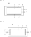
FIGS. 2 to 4 are examples of pouch batteries in which an electrode tab is drawn out in one direction,FIG. 2 illustrates an example in which a gas storage portion is formed on a surface opposite to a surface from which the electrode tab is drawn out,FIG. 3 illustrates an example in which a gas storage portion is formed on the surface from which the electrode tab is drawn out, andFIG. 4 illustrates an example in which a gas storage portion is formed on the surface from which the electrode tab is drawn out and a surface opposite thereto, respectively. -
FIGS. 5 and6 illustrate other examples of pouch batteries in which electrode tabs are drawn out in one direction, andFIGS. 5 and6 illustrate examples in which a gas storage portion is formed on one or both surfaces of a surface from which an electrode tab is drawn out, respectively. -
FIGS. 7 and8 are examples of a pouch battery in which an electrode tab is drawn out in both directions,FIG. 7 illustrates an example in which gas storage portions are formed on both surfaces of a surface from which an electrode tab is drawn out, andFIG. 8 illustrates an example in which gas storage portions are formed on both sides of the surface from which the electrode tabs are drawn out. - An embodiment of the present disclosure is to solve a problem in a pouch forming design due to volume expansion of an anode active material in a battery including an anode, particularly, an anode including a silicon-based active material as an anode material, during a charging/discharging process of the battery. Specifically, when a pouch forming depth is designed without considering the volume expansion of the silicon-based anode material, a problem such as insulation breakdown, or the like, of the electrode due to the volume expansion may occur.
- Meanwhile, considering the volume expansion of the silicon-based anode material as described above, the forming depth of the pouch is designed to be deep so as to have free space, but, due to this free space, there is a high possibility that defects such as pouch folding, or the like, may occur during an insertion process of the electrode assembly into the pouch case or during a storage or transportation process.
- Accordingly, in an embodiment, in order to solve the above-described problem, during a manufacturing process of the battery, the pouch is formed to fit the size of the electrode assembly so that a problem due to free space do not occur, and instead thereof, free space is formed within a pouch battery during the charging/discharging process of the battery. Furthermore, the pouch battery according to an embodiment can improve the lifespan of the battery.
- The present disclosure provides a pouch battery including a gas storage portion in a sealing portion of the pouch battery, and embodiments of the present disclosure will be described in more detail below with reference to the accompanying drawings.
- According to an embodiment, a pouch battery is configured such that an
electrode assembly 11 having a cathode, an anode, and a separator interposed between the cathode and the anode is accommodated in apouch case 20, filled with an electrolyte and then sealed, as illustrated inFIG. 1 . A structure of the electrode assembly 1 is not particularly limited. - For example, the
electrode assembly 11 may be a stacked electrode laminate formed by alternately stacking each separator sheet between cathodes and anodes, a stack-and-fold type electrode laminate in which a long rectangular separator is folded in a zigzag shape and a cathode and an anode are alternately inserted to alternately stack the cathode and anodes, a winding-type electrode laminate formed by alternately stacking anodes and cathodes with the separator as a boundary while winding a rectangular separator in one direction, and may be a jelly roll-type electrode laminate formed by winding together in one direction a long rectangular cathode and anode with a separator interposed between the cathode and the anode. Furthermore, theelectrode assembly 11 may be formed by combining two ormore electrode assemblies 11 of various shapes described above. - A
pouch battery 100 may be provided by sealing thepouch case 20 while theelectrode assembly 11 is inserted into thepouch case 20. In this case, as illustrated inFIG. 1 , thepouch case 20 includes anaccommodation portion 21 having abody portion 31 for accommodating the electrode assembly formed to a predetermined depth to accommodate theelectrode assembly 11, and acover portion 23 covering theaccommodation portion 21, and is manufactured by housing theelectrode assembly 11 in thebody portion 31 of theaccommodation portion 21, folding theaccommodation portion 21 and thecover portion 23 and then heating and pressurizing edges thereof to seal the same. - In this case, the
electrode assembly 11 inserted into thepouch case 20 is electrically connected to the outside of the case through an electrode tab in which a cathode non-coated portion and an anode non-coated portion are assembled, and in thepouch battery 100, a portion of an accommodation space in which theelectrode assembly 11 is located is called abody portion 31, and a portion in which theaccommodation portion 21 and thecover portion 23 is called asealing portion 33. - Although not illustrated in the drawing, the
accommodation portion 21 as well as thecover portion 23 may be formed to a predetermined depth to accommodate theelectrode assembly 11 to have abody portion 31. - Therefore, the
pouch battery 100 provided in an embodiment is a hexahedron in which each electrode having a rectangular planar shape is laminated, similar to theconventional pouch battery 100 illustrated inFIG. 1 . Hereinafter, for convenience, based on the electrode, a surface having a longer length is referred to as a 'long-axis surface', a direction, horizontal to the long-axis surface is referred to as a 'long-axis direction,' a surface having a shorter length is referred to as a 'short-axis surface,' and a direction horizontal to the short-axis surface is referred to as a 'short-axis direction.' In this case, hereinafter, the description is based on an electrode tab being drawn out in a direction of a short-axis surface, but an embodiment thereof is not limited thereto, and an electrode tab may be drawn out in a direction of a long-axis surface. - In the
pouch battery 100, thesealing portion 33 may be formed on three surfaces by using the pouch as illustrated inFIG. 1 . In the case of using a pouch in which theaccommodation portion 21 and thecover portion 23 are separated, asealing portion 33 may be formed on four sides, but there is no particular limitation. - Furthermore, in the
pouch battery 100, as illustrated inFIGS. 1 and2 ,electrode tabs pouch case 20, for example, on a short-axis surface, in a long-axis direction, and as illustrated inFIG. 7 ,electrode tabs - A
pouch battery 100 according to an embodiment has agas storage portion 35 in at least one of the sealingportions 33. Thegas storage portion 35 is formed in a portion of the sealingportion 33, a predetermined space is formed between theaccommodation portion 21 and thecover portion 23 of thepouch case 20, and a gas is stored inside the space. For example, the gas may be CO2, and when CO2 is filled and stored therein, the space may be referred to as a CO2 storage portion. - The
gas storage portion 35 is isolated from abody portion 31 in which anelectrode assembly 11 of thepouch case 20 is accommodated. When thegas storage portion 35 is not isolated from thebody portion 31, it is substantially the same as providing a free space by forming deeper than the shape of theelectrode assembly 11 considering the volume expansion of thepouch battery 100 during the conventional pouch forming, and thus, it may cause a problem of surface defects such as pouch folding, or the like, generated when forming a pouch in consideration of the volume expansion in the conventional case. - To isolate the
body portion 31 and thegas storage portion 35, as described above, anisolation portion 35 is included between thebody portion 31 and thegas storage portion 35. Theisolation portion 37 may be formed by heating and pressurizing theaccommodation portion 21 and thecover portion 23 of the pouch to seal the same, and can be performed by the same method as sealing a pouch in general. - The sealing of the
isolation portion 37 may be released when pressure due to contraction and expansion is applied to thepouch case 20 during the charging/discharging process of the pouch battery, and in this case, a gas stored in thegas storage portion 35, for example, CO2, may be supplied inside the battery to induce the formation of a stable Solid electrolyte Interphase (SEI) layer on a surface of the cathode, thereby improving the lifespan of the battery. - Since a sealing area of the
isolation portion 37 to thegas storage portion 35 is smaller than a sealing area of theother sealing portion 33, when volume expansion occurs inside thepouch case 20, the sealing in theisolation portion 37 may be released more easily due to the pressure resulting from the volume expansion inside the battery. Furthermore, in order to more reliably ensure the release of the sealing in theisolation portion 37 due to volume expansion inside thepouch case 20, sealing strength of theisolation portion 37 may be formed to be weaker than sealing strength of the sealingportion 33. - The sealing strength of the
isolation portion 37 may be set by factors such as a content of a silicon active material included in an anode mixture layer, electrode density, or the like, and is not particularly limited. For example, when the sealing strength of the sealingportion 33 is 100%, the sealing strength of theisolation portion 37 may be 30% or more, for example, 30% to 70%, or 30 to 50%. - More specifically, in a typical pouch battery, the sealing
portion 33 may be designed and manufactured to be about 3 to 5 kgf/cm2, and the sealing strength of theisolation portion 37 may vary depending on the sealing strength of the sealingportion 33, but may be in the range of 1 to 3.5 kgf/cm2, assuming that the sealing strength of theisolation portion 37 is weaker than the sealing strength of the sealingportion 33. - If the sealing strength of the sealing
portion 33 is less than 30% of the sealing strength of theisolation portion 37, the sealing may be released simply by applying pressure to thegas storage portion 35 even when there is no change in pressure inside the battery. This release of the sealing may provide free space in thepouch case 20 and cause wrinkle formation in thepouch case 20. - When designing a battery including a silicon-based anode material, various additives such as fluoroethylene carbonate (FEC), vinylene carbonate (VC), or the like, are added to an electrolyte, to improve the lifespan of the battery. When an anode including a silicon-based anode active material is used, CO2 may form a stable SEI layer on a surface of an anode, thereby improving the cycle performance of the battery. More specifically, CO2 may contribute to forming a stable SEI layer on the surface of graphite particles included an anode active material.
- Therefore, CO2 may be filled in the
gas storage portion 35, located to be spaced apart from thebody portion 31, so that thepouch case 20 may be formed according to the size of theelectrode assembly 11 during a manufacturing process of thepouch battery 100, thereby resolving the problem of surface defects due to folding of the pouch, or the like. When pressure is applied due to volume expansion of the battery module of thepouch case 20, thegas storage portion 35 may be provided as free space, an increase in the pressure applied to the internal pressure due to the volume expansion may be solved, thereby preventing the problem of electrode insulation breakage. - The
gas storage portion 35 may be formed in various shapes and various locations, for example, thegas storage portion 35 may be formed in a sealingportion 33 from which an electrode tab is drawn out or a sealingportion 33 from which the electrode tab is not drawn out, thegas storage portion 35 may be formed in one sealingportion 33 centered on thebody portion 31, and may also be formed in each of the sealingportions 33 facing each other, centered on thebody portion 31, which will be described in more detail with reference to the drawings below. - A
pouch battery 100 according to an embodiment of the present disclosure may be apouch battery 100 in which both ananode tab 15 and acathode tab 13 are drawn out on one side surface of thepouch battery 100, that is, in a direction of one short-axis surface thereof, as illustrated inFIGS. 2 to 6 , and may be apouch battery 100 in which theanode tab 15 and thecathode tab 13 are respectively drawn out on both surfaces of thepouch battery 100, that is, in a direction of short-axis surfaces on both sides thereof, as illustrated inFIGS. 7 and8 . - As an example of an embodiment of a
pouch battery 100 in which both ananode tab 15 and acathode tab 13 are drawn out in a direction of one short-axis surface, as illustrated inFIGS. 2 and 3 , electrode tabs may be drawn out in a direction of one short-axis surface, agas storage portion 35 and anisolation portion 37 may be formed in a sealingportion 33 in a direction the opposite short-axis surface, and may be formed in a sealingportion 33 of a short-axis surface from which the electrode tabs are drawn out. According to another embodiment, thegas storage portion 35 and theisolation portion 37 may be formed on both short-axis sealing portions 33 on both sides thereof, as illustrated inFIG. 4 . - Furthermore, as another embodiment, the
gas storage portion 35 and theisolation portion 37 may be formed in a long-axis sealing portion 33, and as illustrated inFIG. 5 , may be formed in a long-axis sealing portion 33 on one side, and as illustrated inFIG. 6 , thegas storage portion 35 and theisolation portion 37 may be formed in both long-axis sealing portions 33 on both sides. - Furthermore, although not illustrated in the drawing, the
gas storage portion 35 and theisolation portion 37 may be formed together in the sealingportions 33 of the long-axis surface and the short-axis surface, and may be formed in the short-axis sealing portion 33 on one side and long-axis sealing portion 33 on one or more sides thereof, in the long-axis sealing portion 33 on one side and short-axis sealing portion 33 on one or more sides thereof, or in the short-axis sealing portions 33 on both sides and the long-axis sealing portions 33 on both sides thereof. -
FIG. 7 illustrates an embodiment of apouch battery 100 in which ananode tab 15 and acathode tab 13 are drawn out in short-axis surfaces on both sides of thepouch battery 100, respectively, and as illustrated inFIG. 7 , agas storage portion 35 and anisolation portion 37 may be formed in a short-axis sealing portion 33. Specifically, thegas storage portion 35 and theisolation portion 37 may be formed in the short-axis sealing portion 33 on both sides thereof, and, although not illustrated in the drawing, may be formed in one of the short-axis sealing portions 33. - As another example,
FIG. 8 illustrates an embodiment of apouch battery 100 in which ananode tab 15 and acathode tab 13 are respectively drawn out in a direction of short-axis surfaces on both sides thereof. As illustrated inFIG. 8 , agas storage portion 35 and anisolation portion 37 may be formed in the long-axis sealing portion 33. Specifically, thegas storage portion 35 and theisolation portion 37 may be formed in long-axis sealing portions 33 on both sides thereof, and although not illustrated in the drawing, thegas storage portion 35 and theisolation portion 37 may be formed in a long-axis sealing portion 33 on one side thereof. - Furthermore, although not illustrated in the drawing, the
gas storage portion 35 and theisolation portion 37 may be formed together in the long-axis sealing portion 33 and the short-axis sealing portion 33, and thegas storage portion 35 and theisolation portion 37 may be formed in the short-axis sealing portion 33 on one side thereof and long-axis sealing portion 33 on one or more sides thereof, in the long-axis sealing portion 33 on one side thereof and short-axis sealing portion 33 on one or more sides thereof, or in the short-axis sealing portions 33 on both sides thereof and long-axis sealing portions 33 on both sides thereof. - Meanwhile, an embodiment thereof is not limited thereto, the thickness of the gas storage portion may be approximately 5 to 10 mm.
- The
pouch battery 100 according to an embodiment of the present disclosure may include a gas chamber, although not illustrated. The gas chamber is provided as a space for capturing a large amount of gas generated inside thepouch battery 100 during a formation process of thepouch battery 100. - The gas chamber may be formed in an extra pouch outside the
body portion 31, and may include a gas discharge path through which gas generated in thebody portion 31 may move to thebody portion 31, and after the formation is terminated, the gas chamber may be removed after the gas discharge path is closed by sealing. - The gas chamber may be formed on the outside of the sealing
portion 33 in which thegas storage portion 35 and theisolation portion 37 are not formed, and may be formed on the outside of thegas storage portion 35 and theisolation portion 37. - The pouch battery according to the above-described embodiment of the present disclosure may reduce the problem of appearance defects due to volume expansion of a battery, in particular, folding of a pouch in a pouch battery including a silicon-based anode material, and may improve the problem of electrode insulation breakage and error from an initial design value that may occur due to the volume expansion of the silicon-based anode active material during the charging/discharging process.
-
- 100: Pouch Battery
- 11: Electrode Assembly
- 13: Cathode Tab
- 15: Anode Tab
- 20: Pouch Case
- 21: Accommodation Portion
- 23: Cover Portion
- 31: Body Portion
- 33: Sealing Portion
- 35: Gas Storage Portion
- 37: Isolation Portion
Claims (11)
- Provided is a pouch battery in which an electrode assembly is accommodated and sealed in a pouch case including an accommodation portion in which the electrode assembly including a cathode and an anode is accommodated and a cover portion covering the accommodation portion,wherein the pouch battery includes a body portion in which the electrode assembly is located and a sealing portion in which the accommodation portion and the cover portion are sealed, anda gas storage portion and an isolation portion, isolating the gas storage portion from the body portion are included in at least a portion of the sealing portion.
- The pouch battery of claim 1, wherein the gas storage portion and the isolation portion are formed in a sealing portion from which an electrode tab is drawn out from at least one among four surfaces thereof.
- The pouch battery of claim 1, wherein the gas storage portion and the isolation portion are formed in a sealing portion from which an electrode tab is not drawn out from at least one among the four surfaces thereof.
- The pouch battery of claim 1, wherein the gas storage portion and the isolation portion are formed in sealing portions facing each other centered on a body portion.
- The pouch battery of claim 1, wherein the isolation portion has a weaker sealing strength than the sealing portion.
- The pouch battery of claim 5, wherein the sealing strength of the isolation portion is 1 to 3.5 kgf/cm2.
- The pouch battery of claim 1, wherein the sealing portion is formed on three or four surfaces of an edge of the body portion.
- The pouch battery of claim 1, wherein a gas contained in the gas storage portion is CO2.
- The pouch battery of claim 1, wherein the anode contains a silicon-based active material.
- The pouch battery of claim 1, wherein the pouch battery contains an electrolyte, and the electrolyte contains CO2.
- The pouch battery of one of claims 1 to 10, further comprising:
a gas chamber.
Applications Claiming Priority (2)
| Application Number | Priority Date | Filing Date | Title |
|---|---|---|---|
| KR1020220142856A KR20240062368A (en) | 2022-10-31 | 2022-10-31 | Pouch battery |
| PCT/KR2023/008964 WO2024096236A1 (en) | 2022-10-31 | 2023-06-27 | Pouch battery |
Publications (2)
| Publication Number | Publication Date |
|---|---|
| EP4539219A1 true EP4539219A1 (en) | 2025-04-16 |
| EP4539219A4 EP4539219A4 (en) | 2025-11-26 |
Family
ID=90930649
Family Applications (1)
| Application Number | Title | Priority Date | Filing Date |
|---|---|---|---|
| EP23885933.4A Pending EP4539219A4 (en) | 2022-10-31 | 2023-06-27 | POUCH BATTERY |
Country Status (4)
| Country | Link |
|---|---|
| EP (1) | EP4539219A4 (en) |
| KR (1) | KR20240062368A (en) |
| CN (1) | CN119452510A (en) |
| WO (1) | WO2024096236A1 (en) |
Family Cites Families (7)
| Publication number | Priority date | Publication date | Assignee | Title |
|---|---|---|---|---|
| JP2007095445A (en) * | 2005-09-28 | 2007-04-12 | Sanyo Electric Co Ltd | Nonaqueous electrolyte secondary battery |
| KR101833540B1 (en) * | 2014-08-14 | 2018-03-02 | 주식회사 엘지화학 | Battery Cell Having Means For Venting The Gas |
| CN105489925B (en) * | 2015-11-24 | 2018-02-06 | 山东精工电子科技有限公司 | A kind of soft bag lithium ionic cell and preparation method thereof |
| KR101879869B1 (en) * | 2016-11-03 | 2018-07-19 | 현대자동차주식회사 | Pouch battery |
| CN106654354A (en) * | 2016-11-29 | 2017-05-10 | 天津中聚新能源科技有限公司 | Lithium-ion battery and package detection method thereof |
| KR102203839B1 (en) * | 2018-01-09 | 2021-01-15 | 주식회사 엘지화학 | Pouch cell case having hidden-type gas pocket, pouch cell with the same, and battery module with the same |
| KR102334022B1 (en) * | 2018-11-02 | 2021-12-02 | 주식회사 엘지에너지솔루션 | Pouch-type Secondary Battery Having Groove for Replenishing an electrolyte |
-
2022
- 2022-10-31 KR KR1020220142856A patent/KR20240062368A/en active Pending
-
2023
- 2023-06-27 WO PCT/KR2023/008964 patent/WO2024096236A1/en not_active Ceased
- 2023-06-27 CN CN202380052786.9A patent/CN119452510A/en active Pending
- 2023-06-27 EP EP23885933.4A patent/EP4539219A4/en active Pending
Also Published As
| Publication number | Publication date |
|---|---|
| KR20240062368A (en) | 2024-05-09 |
| CN119452510A (en) | 2025-02-14 |
| WO2024096236A1 (en) | 2024-05-10 |
| EP4539219A4 (en) | 2025-11-26 |
Similar Documents
| Publication | Publication Date | Title |
|---|---|---|
| JP6884795B2 (en) | Stepped electrochemical cell with folded encapsulation | |
| KR101636371B1 (en) | Battery Cell of Stair-like Structure | |
| KR100876455B1 (en) | Pouch type secondary battery with unsealed surplus | |
| KR101165066B1 (en) | Pouch-type secondary battery comprising a portion of non-sealing residue | |
| US12199246B2 (en) | Stacked prismatic architecture for electrochemical cell | |
| US20140154554A1 (en) | Battery module | |
| KR20120051424A (en) | Lithium secondary battery and manufacturing method of the same | |
| KR101403692B1 (en) | Pouch for battery, and pouch type battery including the same | |
| EP3639316A1 (en) | Stacked prismatic architecture for electrochemical cell | |
| KR20100126226A (en) | Water resistant pouch type secondary battery | |
| KR102616196B1 (en) | Battery cell and battery module including the same | |
| KR20140103402A (en) | Pouch for battery, and pouch type battery including the same | |
| EP4300647A1 (en) | Electrode assembly and battery cell including same | |
| KR102681885B1 (en) | Battery cell and battery module including the same | |
| KR101491721B1 (en) | Pouch-type secondary battery & manufacturing thereof | |
| KR20150030861A (en) | Pouched type case, battery cell and manufacturing method of battery cell | |
| WO2012027013A1 (en) | Advanced high durability lithium-ion battery | |
| KR100513645B1 (en) | The laminated cell with the outmost electrode pocketed by two separators | |
| KR101368236B1 (en) | Secondary battery having a plastic-bag, and manufacturing the same | |
| KR20230038052A (en) | Rechargeable battery manufacturing method | |
| KR20240062368A (en) | Pouch battery | |
| KR20160015098A (en) | A secondary battery with improved wetting property and a method for manufacturing the same | |
| KR20100135622A (en) | Secondary battery and secondary battery manufacturing method excellent in sealing property | |
| KR20160098148A (en) | Pouched type case, battery cell and manufacturing method of battery cell | |
| JP7859397B2 (en) | Method for manufacturing energy storage cells and electrodes |
Legal Events
| Date | Code | Title | Description |
|---|---|---|---|
| STAA | Information on the status of an ep patent application or granted ep patent |
Free format text: STATUS: THE INTERNATIONAL PUBLICATION HAS BEEN MADE |
|
| PUAI | Public reference made under article 153(3) epc to a published international application that has entered the european phase |
Free format text: ORIGINAL CODE: 0009012 |
|
| STAA | Information on the status of an ep patent application or granted ep patent |
Free format text: STATUS: REQUEST FOR EXAMINATION WAS MADE |
|
| 17P | Request for examination filed |
Effective date: 20250113 |
|
| AK | Designated contracting states |
Kind code of ref document: A1 Designated state(s): AL AT BE BG CH CY CZ DE DK EE ES FI FR GB GR HR HU IE IS IT LI LT LU LV MC ME MK MT NL NO PL PT RO RS SE SI SK SM TR |
|
| A4 | Supplementary search report drawn up and despatched |
Effective date: 20251027 |
|
| RIC1 | Information provided on ipc code assigned before grant |
Ipc: H01M 50/186 20210101AFI20251021BHEP Ipc: H01M 50/572 20210101ALI20251021BHEP Ipc: H01M 50/178 20210101ALI20251021BHEP Ipc: H01M 4/38 20060101ALI20251021BHEP Ipc: H01M 50/105 20210101ALI20251021BHEP |
|
| DAV | Request for validation of the european patent (deleted) | ||
| DAX | Request for extension of the european patent (deleted) |