EP4539216A2 - A method for manufacturing a supercapacitor - Google Patents
A method for manufacturing a supercapacitor Download PDFInfo
- Publication number
- EP4539216A2 EP4539216A2 EP25161410.3A EP25161410A EP4539216A2 EP 4539216 A2 EP4539216 A2 EP 4539216A2 EP 25161410 A EP25161410 A EP 25161410A EP 4539216 A2 EP4539216 A2 EP 4539216A2
- Authority
- EP
- European Patent Office
- Prior art keywords
- electrode assembly
- electrolyte
- cell body
- lid
- sealing
- Prior art date
- Legal status (The legal status is an assumption and is not a legal conclusion. Google has not performed a legal analysis and makes no representation as to the accuracy of the status listed.)
- Pending
Links
Images


Classifications
-
- H—ELECTRICITY
- H01—ELECTRIC ELEMENTS
- H01G—CAPACITORS; CAPACITORS, RECTIFIERS, DETECTORS, SWITCHING DEVICES, LIGHT-SENSITIVE OR TEMPERATURE-SENSITIVE DEVICES OF THE ELECTROLYTIC TYPE
- H01G11/00—Hybrid capacitors, i.e. capacitors having different positive and negative electrodes; Electric double-layer [EDL] capacitors; Processes for the manufacture thereof or of parts thereof
- H01G11/78—Cases; Housings; Encapsulations; Mountings
- H01G11/82—Fixing or assembling a capacitive element in a housing, e.g. mounting electrodes, current collectors or terminals in containers or encapsulations
-
- H—ELECTRICITY
- H01—ELECTRIC ELEMENTS
- H01G—CAPACITORS; CAPACITORS, RECTIFIERS, DETECTORS, SWITCHING DEVICES, LIGHT-SENSITIVE OR TEMPERATURE-SENSITIVE DEVICES OF THE ELECTROLYTIC TYPE
- H01G11/00—Hybrid capacitors, i.e. capacitors having different positive and negative electrodes; Electric double-layer [EDL] capacitors; Processes for the manufacture thereof or of parts thereof
- H01G11/74—Terminals, e.g. extensions of current collectors
-
- H—ELECTRICITY
- H01—ELECTRIC ELEMENTS
- H01G—CAPACITORS; CAPACITORS, RECTIFIERS, DETECTORS, SWITCHING DEVICES, LIGHT-SENSITIVE OR TEMPERATURE-SENSITIVE DEVICES OF THE ELECTROLYTIC TYPE
- H01G11/00—Hybrid capacitors, i.e. capacitors having different positive and negative electrodes; Electric double-layer [EDL] capacitors; Processes for the manufacture thereof or of parts thereof
- H01G11/78—Cases; Housings; Encapsulations; Mountings
- H01G11/80—Gaskets; Sealings
-
- H—ELECTRICITY
- H01—ELECTRIC ELEMENTS
- H01G—CAPACITORS; CAPACITORS, RECTIFIERS, DETECTORS, SWITCHING DEVICES, LIGHT-SENSITIVE OR TEMPERATURE-SENSITIVE DEVICES OF THE ELECTROLYTIC TYPE
- H01G11/00—Hybrid capacitors, i.e. capacitors having different positive and negative electrodes; Electric double-layer [EDL] capacitors; Processes for the manufacture thereof or of parts thereof
- H01G11/14—Arrangements or processes for adjusting or protecting hybrid or EDL capacitors
- H01G11/18—Arrangements or processes for adjusting or protecting hybrid or EDL capacitors against thermal overloads, e.g. heating, cooling or ventilating
-
- H—ELECTRICITY
- H01—ELECTRIC ELEMENTS
- H01G—CAPACITORS; CAPACITORS, RECTIFIERS, DETECTORS, SWITCHING DEVICES, LIGHT-SENSITIVE OR TEMPERATURE-SENSITIVE DEVICES OF THE ELECTROLYTIC TYPE
- H01G2/00—Details of capacitors not covered by a single one of groups H01G4/00-H01G11/00
- H01G2/08—Cooling arrangements; Heating arrangements; Ventilating arrangements
-
- H—ELECTRICITY
- H01—ELECTRIC ELEMENTS
- H01M—PROCESSES OR MEANS, e.g. BATTERIES, FOR THE DIRECT CONVERSION OF CHEMICAL ENERGY INTO ELECTRICAL ENERGY
- H01M50/00—Constructional details or processes of manufacture of the non-active parts of electrochemical cells other than fuel cells, e.g. hybrid cells
- H01M50/10—Primary casings; Jackets or wrappings
- H01M50/183—Sealing members
-
- Y—GENERAL TAGGING OF NEW TECHNOLOGICAL DEVELOPMENTS; GENERAL TAGGING OF CROSS-SECTIONAL TECHNOLOGIES SPANNING OVER SEVERAL SECTIONS OF THE IPC; TECHNICAL SUBJECTS COVERED BY FORMER USPC CROSS-REFERENCE ART COLLECTIONS [XRACs] AND DIGESTS
- Y02—TECHNOLOGIES OR APPLICATIONS FOR MITIGATION OR ADAPTATION AGAINST CLIMATE CHANGE
- Y02E—REDUCTION OF GREENHOUSE GAS [GHG] EMISSIONS, RELATED TO ENERGY GENERATION, TRANSMISSION OR DISTRIBUTION
- Y02E60/00—Enabling technologies; Technologies with a potential or indirect contribution to GHG emissions mitigation
- Y02E60/13—Energy storage using capacitors
Definitions
- step b) comprises welding a current tab member to the electrode assembly before inserting the electrode assembly with the current tab member facing away from the bottom portion.
- the electrode assembly comprises an insulating member that is arranged to electrically insulate the current tab member from the cell body, preferably form the wall portion, when the electrode assembly is inserted into the cell body.
- step d) cooling is performed such that the electrolyte is kept below its flash point.
- the lid assembly comprises a sealing member that has at least one wiper portion, wherein, upon inserting the lid assembly, the wiper portion is wiping electrolyte present on the wall portion towards the bottom portion.
- the electrode assembly is a wound electrode assembly.
- step f) comprises cooling the electrolyte before injecting of the electrolyte.
- step f) comprises cooling the electrolyte during injecting of the electrolyte.
- step f) comprises cooling the electrolyte for a predetermined amount of time after injecting of the electrolyte.
- step f) comprises cooling the cell body and/or the electrode assembly before injecting of the electrolyte.
- step f) comprises cooling the cell body and/or the electrode assembly during injecting of the electrolyte.
- step f) comprises cooling the cell body and/or the electrode assembly for a predetermined amount of time after injecting of the electrolyte.
- step f) cooling is performed such that the electrolyte is prevented from boiling.
- the laser beam is directed parallel to the wall portion so as to impinge on a boundary area between the plug member and the bottom portion.
- the laser beam is directed parallel to the wall portion so as to impinge on a boundary area between the bottom current tab member.
- the electrode assembly is welded to the bottom portion with one continuous weld seam that is longer than the length of the exterior groove along ist longitudinal direction or with at least two weld seams.
- the lid member comprises a first expansion chamber portion that includes a second support protrusion that protrudes towards the sealing member and contacts the sealing member, wherein the second support portion is disposed radially inward from a circumferential rim portion of the lid member.
- the sealing member comprises a second expansion chamber portion that includes a chamber bottom portion, that extends substantially parallel to the lid member.
- the sealing member comprises a first sealing groove that is disposed on a circumferential rim portion of the sealing member, and the first sealing groove has inserted therein a portion of the lid member, preferably the first support protrusion.
- the lid member comprises a welding groove that is disposed on a circumferential rim portion of the lid base portion.
- the welding groove includes a groove sidewall that is disposed on the outermost circumference of the lid base portion.
- the lid base portion includes a welding surface that is disposed on the outermost circumference of the lid base portion.
- the welding surface includes a surface of the groove sidewall.
- the first support protrusion tapers downward.
- the invention provides a current tab member for an electrode assembly of an energy storage cell, e.g. a supercapacitor, the electrode assembly comprising a negative electrode and a positive electrode, each electrode including a carbon material that includes micropores, and the electrodes are separated by a separator, wherein the current tab member comprises:
- the heat sink portion includes at least one tapered heat sink portion that tapers from the contacting portion towards the terminal portion.
- the sealing opening includes a tapered sealing portion that expands downward, wherein the tapered sealing portion is in contact with the heat sink portion.
- the lid assembly comprises an electrically conductive lid member, wherein the lid member and the sealing member are configured to cooperatively form an expansion chamber that is arranged between the lid member and the sealing member, wherein the expansion chamber is fluidly connectable to an interior of the cell body, and the current tab member is in contact with the sealing member and electrically insulated from the lid member by the sealing member.
- the invention provides a cell body kit-of-parts for forming a cell body of a supercapacitor, the kit-of-parts comprising a cell body having a bottom portion, a wall portion, and a top opening; a previously described lid assembly, that is insertable into the top opening so as to form a closed off cell interior.
- the cell body 2 may comprise a bottom portion 21.
- the bottom portion may be generally disk-shaped.
- the bottom portion 21 may be formed as a massive portion without discontinuities.
- the cell body 2 may include a wall portion 22.
- the wall portion 22 may extend upward in the axial direction.
- the wall portion 22 may extend along a circumferential direction of the cell body 2, so as to form an open can shape.
- the wall portion 22 may have at least one predetermined breaking portion 221.
- the predetermined breaking portion 221 is configured such that at a predetermined pressure inside the cell body 2, the predetermined breaking portion 221 structurally fails and releases the pressure from the cell body 2.
- the bottom portion 21, the wall portion 22 and the top opening 23 may define a cell interior 25.
- the cell interior 25 is that volume of the cell body 2 that, when the top opening 23 is closed, e.g. by a lid, is inside the cell body 2.
- the energy storage cell 1 may include an electrolyte 4.
- the electrolyte 4 can be any suitable electrolyte used in supercapacitors.
- the electrolyte 4 is also arranged within the cell interior 25.
- the energy storage cell 1 may comprise a lid assembly 5.
- the lid assembly 5 can be inserted through the top opening 23 such that the cell interior 25 is closed off from the outside of the cell body 2.
- the lid assembly 5 can be fixed to the wall portion 22, preferably by welding.
- the lid assembly 5 may include a lid member 51.
- the lid member 51 is generally a flat extended member that is suitable to be inserted into the top opening 23. As depicted here, the lid member 51 is generally disk-shaped.
- the lid member 51 may include a first expansion chamber portion 511.
- the first expansion chamber portion 511 is formed in the lid member 51.
- the first expansion chamber portion 511 may include a chamber top portion 511a, which is preferably partially formed by a lid base portion 512.
- the first expansion chamber portion 511 may include a first support protrusion 511b.
- the first support protrusion 511b may be arranged on an outer rim portion.
- the first support protrusion 511b may protrude from the chamber top portion 511a axially downward.
- the first support protrusion 511b preferably extends along the whole circumferential direction along the outer rim portion.
- the first expansion chamber portion 511 may include a second support protrusion 511c.
- the second support protrusion 511c may protrude from the chamber top portion 511a axially downward.
- the second support protrusion 511c may be recessed relative to the first support protrusion 511b along the axial direction. In other words, the second support protrusion 511c need not extend as far downward as the first support protrusion 511b.
- the second support protrusion 511c may be arranged radially closer to the center portion of the lid member 51 than the first support protrusion 511b.
- the lid member 51 may include a lid opening 513.
- the lid opening 513 is preferably arranged on the center portion of the lid base portion 512.
- the lid opening 513 may include a circumferential vertical wall 513a.
- the circumferential vertical wall 513a may extend in an axial direction.
- the circumferential vertical wall 513a may be configured as a vertical sealing surface 513b for forming a seal.
- the lid opening 513 may further include a tapered circumferential wall 513c.
- the tapered circumferential wall 513c may begin at the bottom of the circumferential wall 513a.
- the tapered circumferential wall 513c may increase in diameter downward in the axial direction.
- the tapered circumferential wall 513c may be configured as a tapered sealing surface 513d for forming a seal.
- the sealing member 52 may include a second expansion chamber portion 521.
- the second expansion chamber portion 521 is configured to match with the first expansion chamber portion 511.
- the second expansion chamber portion 521 may include a chamber bottom portion 521a.
- the second expansion chamber portion 521 may include a first sealing groove 521b.
- the first sealing groove 521b may face axially upward from the chamber bottom portion 521a. Sidewalls of the first sealing groove 521b may protrude axially upward.
- the first sealing groove 521b may be arranged on an outer rim portion of the sealing member 52.
- the first sealing groove 521b preferably extends along the entire circumference of the sealing member 52.
- the second expansion chamber portion 521 may include a second sealing groove 521c.
- the second sealing groove 521c may be formed radially closer to the center portion of the sealing member 52 than the first sealing groove 521b.
- the first sealing groove 521b and the second sealing groove 521c may form sidewalls of the second expansion chamber portion 521.
- the chamber bottom portion 521a may form a base of the second expansion chamber portion 521.
- the sealing opening 523 may include a tapered sealing portion 523c.
- the tapered sealing portion 523c may be formed adjacent to the circumferential sidewall 523a.
- the tapered sealing portion 523c may face away from the sealing shroud 523b.
- the tapered sealing portion 523c may expand downward in the axial direction.
- the current tab member 7 may include a terminal portion 71.
- the terminal portion 71 may be arranged at a center portion of the current tab member 7.
- the terminal portion 71 may be formed such that the terminal portion 71 can be inserted into the sealing opening 523.
- the terminal portion 71 may be formed such that the terminal portion 71 can protrude through the lid opening 513.
- the terminal portion 71 may have a height such that in an installed position, the terminal portion 71 protrudes from the lid member 51.
- the heat sink portion 73 may include a plurality of thermal conductive leg portions 733.
- the thermal conductive leg portion 733 may extend from the tapered heat sink portion 731 preferably along the contacting portion 722.
- the thermal conductive leg portion 733 may form a sidewall of the tab welding groove 722.
- the thermal conductive leg portion 733 may have a much larger axial thickness (4 to 8 times) compared to the axial thickness of the tab welding portion 721.
- the cell body 2 and the electrode assembly 3 are brought to a filling station for the electrolyte 4. Therein, a vacuum, below 300 mb, preferably from 10 to 100 mb (rough vacuum) is applied.
- the electrolyte 4 is filled through the top opening 23 into the cell interior 25.
- the electrode assembly 3, as it is typically configured for supercapacitors, includes electrodes having a microporous (carbon) material.
- the electrolyte 4 adsorbs into the micropores, thereby generating adsorption heat which may heat the electrolyte 4 above boiling point.
- the electrolyte 4 may therefore be added not at once, but in several steps of adding some electrolyte 4, waiting for a predetermined amount of time and then again adding some electrolyte 4.
- the lid assembly 5 After enough electrolyte 4 was added to the cell body 2, preferably still under the vacuum, the lid assembly 5 is inserted into the top opening 23. During insertion of the lid assembly 5, the sealing member 52, specifically the wiper portion 524, wipes any electrolyte from the wall portion 22 towards the bottom portion 21. As a result, the lid member 51, specifically the welding surface 515b, makes contact with a part of the wall portion 22 that has been cleaned from electrolyte 4 by the lid assembly 5.
- the electrode assembly 3 is inserted into the cell interior 25 and welded to the bottom portion 21, as previously described. Furthermore, the lid assembly 5 is inserted into the top opening 23 to close off the cell interior 25 from the environment. The lid assembly 5 is welded to the cell body 2, specifically, to the wall portion 22, as previously described.
- this type of cell may also be filled faster with electrolyte 4 compared to the known methods.
- the configuration ensures that, even if boiling of the electrolyte 4 cannot be prevented, the electrolyte 4 is still contained in the cell interior and the pressure relieved such that the cell body 2 is still sealed.
- the electrolyte 4 behaves as previously described and may go into the expansion chamber 6, thereby avoiding a burst pressure of the predetermined breaking portion 221.
- the comparatively thick bottom portion 21 can act as a heat sink.
Landscapes
- Engineering & Computer Science (AREA)
- Power Engineering (AREA)
- Microelectronics & Electronic Packaging (AREA)
- Electric Double-Layer Capacitors Or The Like (AREA)
- Sealing Battery Cases Or Jackets (AREA)
- Connection Of Batteries Or Terminals (AREA)
Abstract
a) providing a cell body (2) that has a bottom portion (21), a wall portion (22), and a top opening (23), wherein the cell body (2) is integrally formed as a single unitary member, and the bottom portion (21) has provided therein a bottom fluid passage (213);
b) inserting through the top opening (23) an electrode assembly (3) that has a negative electrode and a positive electrode, and the electrodes are separated by a separator, preferably each electrode including an active material, e.g. a carbon material, that includes micropores;
c) fixing the electrode assembly (3) to the bottom portion (21) in an electrically conductive manner;
d) closing the top opening (23) with a lid assembly (5) thereby forming a cell interior (25) that contains the electrode assembly (3) in a dry state, and fixing the lid assembly (5) to the cell body (2);
e) orienting the cell body (2) such that the bottom fluid passage (213) is facing downward in a vertical direction;
f) injecting an electrolyte (4) through the bottom fluid passage (213) such that the electrode assembly (3) gets wetted by the electrolyte (4);
g) closing the bottom fluid passage (213) with a plug member (24) and fixing the plug member (24) to the bottom portion (21), thereby obtaining the supercapacitor (11).
Description
- The invention relates to a method for manufacturing a supercapacitor.
- The invention relates to a lid assembly for an energy storage cell, e.g. a supercapacitor. Furthermore, the invention relates to a kit-of-parts and an energy storage cell that comprise the lid assembly.
- The invention relates to a current tab member for an electrode assembly of an energy storage cell, e.g. a supercapacitor. Furthermore, the invention relates to a kit-of-parts and an energy storage cell that comprise the current tab member.
-
US 2003 / 0 086 239 A1 discloses a method of making a double layer capacitor that includes coupling a top collector disk to a proximal end of a double layer capacitor electrode assembly; electrically coupling a bottom collector disk to a distal end; heating a can; inserting the double layer capacitor electrode assembly into the can; cooling the can, wherein a peripheral edge of the bottom collector disk is coupled to the can as the diameter of the can is decreased; forming a bead around an exterior of the can; heating a lid; placing a concave structure of the lid in juxtaposition with a convex structure on the top collector disk; cooling the lid, wherein the concave structure is coupled to the convex structure as the diameter of the can is decreased; creating a seal between the lid and the can; and placing an electrolyte solution into the electrode assembly. -
FR 1 439 148 A -
EP 1 756 843 A1 discloses an electric energy storage component having coil windings and at least one connector. A plate of the connector is in contact with the coil windings. The plate of the connector has a surface which is provided with a terminal wherein the shape thereof is essentially that of a revolution. The plate also forms a series of bosses extending in a raised manner along a surface of the plate opposite to that containing the terminal. The terminal has at least one inner recess and at least one boss which penetrates into the recess. -
EP 1 642 894 A1 discloses a quaternary ammonium salt and electrolytic solution in a electrochemical device using the salt. -
CN 104 795 257 A discloses a power capacitor immersion treatment method. The power capacitor immersion treatment method includes putting a to-be-treated power capacitor in a vacuum tank, and vacuumizing the power capacitor and the vacuum tank to form a vacuum cavity of 0.09MPa; heating the power capacitor to 80-90 °C for 12 hours; lowering the internal temperature of the power capacitor to 70-80 °C, increasing the gas partial pressure vacuum degree in the vacuum tank to 0.5-1 Pa gradually, and keeping the gas partial pressure vacuum degree for 12 hours; starting ultrasonic wave generation components on the outer wall of the power capacitor, and lowering the internal temperature of the power capacitor to 40-60 °C; lowering the internal temperature of the power capacitor to below 30 °C, opening a vacuum degree breakage valve to allow communication with the atmosphere, taking the power capacitor out of the tank, filling the power capacitor with oil and sealing an oil filling hole. The power capacitor immersion treatment method has the advantages that gas blended in the insulating dielectric oil, air among solid dielectric layers of capacitor components and air between the solid dielectric layers and pole plate aluminum foil layers are removed thoroughly. - In industrial applications supercapacitors are typically manufactured using cylindrical cans, for example, for the convenience of mass production. Specifically, supercapacitors that are based on microporous carbon seem to be the way of the future. However, it is not always easy to fill the electrolyte into the can.
- Currently, the can is closed with a lid that has a small opening through which the electrolyte is introduced. When coming into contact with the electrode assembly, the electrolyte typically adsorbs to the micropores thereby releasing energy in the form of heat. The typical electrolyte compositions that are used have a rather low boiling point and may start to boil from the adsorption heat alone. It is therefore possible for the electrolyte to spill from the small opening in the lid possibly causing delays in manufacturing.
- It should be noted that due to the much smaller overall electrode surface, conventional batteries, e.g. lithium ion batteries, do not experience this phenomenon.
- The object of the invention is to provide an improved manufacturing method that preferably allows to reduce delays in manufacturing and/or to improve the production rate.
- The object is achieved by the subject-matter of the independent claims. Preferred embodiments are subject-matter of the dependent claims.
- The invention provides a method for manufacturing a supercapacitor for storing electrical energy, the method comprising:
- a) providing a cell body that has a bottom portion, a wall portion, and a top opening, wherein the cell body is integrally formed as a single unitary member;
- b) inserting through the top opening an electrode assembly that has a negative electrode and a positive electrode, and the electrodes are separated by a separator, preferably each electrode including an active material, e.g. a carbon material, that includes micropores;
- c) fixing the electrode assembly to the bottom portion in an electrically conductive manner;
- d) filling an electrolyte through the top opening so that the electrode assembly gets immersed in the electrolyte;
- e) closing the top opening with a lid assembly thereby forming a cell interior that contains the electrode assembly immersed in the electrolyte; and
- f) fixing the lid assembly to the cell body, thereby obtaining the supercapacitor.
- Preferably, the bottom portion is formed as a unitary portion without discontinuities or cavities in the material.
- Preferably, in step a) the bottom portion is provided with a bottom protrusion that protrudes outside the cell body in an axial direction.
- Preferably, in step a) the bottom protrusion is provided in the center of the bottom portion and the at least one exterior welding groove extends from the bottom protrusion in a radial direction towards the periphery.
- Preferably, in step b) the electrode assembly is a wound electrode assembly.
- Preferably, step b) comprises welding a current tab member to the electrode assembly before inserting the electrode assembly with the current tab member facing away from the bottom portion.
- Preferably, the electrode assembly has a current tab member welded thereon before inserting the electrode assembly with the current tab member facing away from the bottom portion.
- Preferably, the electrode assembly comprises an insulating member that is arranged to electrically insulate the current tab member from the cell body, preferably form the wall portion, when the electrode assembly is inserted into the cell body.
- Preferably, step b) comprises inserting through the top opening a current tab member and contacting the electrode assembly with the current tab member.
- Preferably, step c) comprises fixing the current tab member to the electrode assembly.
- Preferably, step c) comprises welding the current tab member to the electrode assembly.
- Preferably, step c) includes welding the electrode assembly to the bottom portion.
- Preferably, in step c) the electrode assembly is welded to the bottom portion with one continuous weld seam that is longer than the length of the exterior groove along ist longitudinal direction or with at least two weld seams.
- Preferably, in step a) the bottom portion is provided with at least one exterior welding groove that includes a welding groove base, and in step c) the electrode assembly is welded to the welding groove base by welding from outside the cell body.
- Preferably, step d) comprises cooling the electrolyte before filling of the electrolyte. Preferably, step d) comprises cooling the electrolyte during filling of the electrolyte. Preferably, step d) comprises cooling the electrolyte for a predetermined amount of time after filling of the electrolyte.
- Preferably, step d) comprises contacting the cell body and/or the electrode assembly with a heat sink before filling of the electrolyte. Preferably, step d) comprises contacting the cell body and/or the electrode assembly with a heat sink during filling of the electrolyte. Preferably, step d) comprises contacting the cell body and/or the electrode assembly with a heat sink for a predetermined amount of time after filling of the electrolyte.
- Preferably, step d) comprises cooling the cell body and/or the electrode assembly before filling of the electrolyte. Preferably, step d) comprises cooling the cell body and/or the electrode assembly during filling of the electrolyte. Preferably, step d) comprises cooling the cell body and/or the electrode assembly for a predetermined amount of time after filling of the electrolyte.
- Preferably, in step d) cooling is performed such that the electrolyte is prevented from boiling.
- Preferably, in step d) cooling is performed such that the electrolyte is kept below its flash point.
- Preferably, in step e) during closing the top opening electrolyte present on the wall portion is wiped towards the bottom portion by the lid assembly.
- Preferably, the lid assembly comprises a sealing member that has at least one wiper portion, wherein, upon inserting the lid assembly, the wiper portion is wiping electrolyte present on the wall portion towards the bottom portion.
- Preferably, in step e) closing the top opening includes inserting the lid assembly into the top opening.
- Preferably, step f) comprises welding the lid assembly to the cell body.
- Preferably, step f) comprises laser welding the lid assembly to the cell body.
- Preferably, the laser beam is directed parallel to the wall portion so as to impinge on a boundary area between the lid assembly and the wall portion.
- Preferably, at least the steps d), e) and f) are performed under vacuum.
- The invention provides a supercapacitor that is obtainable by performing a previously described method.
- The invention provides a method for manufacturing a supercapacitor for storing electrical energy, the method comprising:
- a) providing a cell body that has a bottom portion, a wall portion, and a top opening, wherein the cell body is integrally formed as a single unitary member, and the bottom portion has provided therein a bottom fluid passage;
- b) inserting through the top opening an electrode assembly that has a negative electrode and a positive electrode, and the electrodes are separated by a separator, preferably each electrode including an active material, e.g. a carbon material, that includes micropores;
- c) fixing the electrode assembly to the bottom portion in an electrically conductive manner;
- d) closing the top opening with a lid assembly thereby forming a cell interior that contains the electrode assembly in a dry state, and fixing the lid assembly to the cell body;
- e) orienting the cell body such that the bottom fluid passage is facing downward in a vertical direction;
- f) injecting an electrolyte through the bottom fluid passage such that the electrode assembly gets wetted by the electrolyte;
- g) closing the bottom fluid passage with a plug member and fixing the plug member to the bottom portion, thereby obtaining the supercapacitor.
- Preferably, the steps d), e) and f) are performed in the order d) - e) - f). Preferably, the steps d), e) and f) are performed in the order e) - f) - d).
- Preferably, at least step f) is performed under vacuum.
- Preferably, in step a) the bottom portion is provided with a bottom protrusion that protrudes outside the cell body in an axial direction, and the bottom fluid passage is formed on the bottom protrusion.
- Preferably, in step a) the bottom protrusion is provided in the center of the bottom portion and at least one exterior welding groove extends from the bottom protrusion in a radial direction towards the periphery.
- Preferably, in step a) the bottom portion is formed as a unitary portion without discontinuities or cavities in the material.
- Preferably, in step b) the electrode assembly is a wound electrode assembly.
- Preferably, step b) comprises welding a current tab member to the electrode assembly before inserting the electrode assembly with the current tab member facing away from the bottom portion.
- Preferably, the electrode assembly has a current tab member welded thereon before inserting the electrode assembly with the current tab member facing away from the bottom portion.
- Preferably, step b) comprises welding a bottom current tab member to the electrode assembly before inserting the electrode assembly with the bottom current tab member contacting the bottom portion.
- Preferably, in step b) the electrode assembly has a bottom current tab member welded thereon before inserting the electrode assembly with the bottom current tab member contacting the bottom portion.
- Preferably, in step c) the bottom current tab member is welded to the bottom portion.
- Preferably, step f) comprises cooling the electrolyte before injecting of the electrolyte. Preferably, step f) comprises cooling the electrolyte during injecting of the electrolyte. Preferably, step f) comprises cooling the electrolyte for a predetermined amount of time after injecting of the electrolyte.
- Preferably, step f) comprises contacting the cell body and/or the electrode assembly with a heat sink before injecting of the electrolyte. Preferably, step f) comprises contacting the cell body and/or the electrode assembly with a heat sink during injecting of the electrolyte. Preferably, step f) comprises contacting the cell body and/or the electrode assembly with a heat sink for a predetermined amount of time after injecting of the electrolyte.
- Preferably, step f) comprises cooling the cell body and/or the electrode assembly before injecting of the electrolyte. Preferably, step f) comprises cooling the cell body and/or the electrode assembly during injecting of the electrolyte. Preferably, step f) comprises cooling the cell body and/or the electrode assembly for a predetermined amount of time after injecting of the electrolyte.
- Preferably, in step f) cooling is performed such that the electrolyte is prevented from boiling.
- Preferably, in step f) cooling is performed such that the electrolyte is kept below its flash point.
- Preferably, in step g) the plug member is fixed by welding to the bottom portion. Preferably, in step g) the plug member is fixed by welding to the bottom current tab member.
- Preferably, step g) comprises laser welding the plug member to the bottom portion. Preferably, step g) comprises laser welding the plug member to the bottom current tab member.
- Preferably, the laser beam is directed parallel to the wall portion so as to impinge on a boundary area between the plug member and the bottom portion. Preferably, the laser beam is directed parallel to the wall portion so as to impinge on a boundary area between the bottom current tab member.
- Preferably, the electrode assembly comprises an insulating member that is arranged to electrically insulate the current tab member from the cell body, preferably form the wall portion, when the electrode assembly is inserted into the cell body.
- Preferably, step b) comprises inserting through the top opening a current tab member and contacting the electrode assembly with the current tab member.
- Preferably, step c) comprises fixing the current tab member to the electrode assembly.
- Preferably, step c) comprises welding the current tab member to the electrode assembly.
- Preferably, step c) includes welding the electrode assembly to the bottom portion.
- Preferably, in step c) the electrode assembly is welded to the bottom portion with one continuous weld seam that is longer than the length of the exterior groove along ist longitudinal direction or with at least two weld seams.
- Preferably, in step a) the bottom portion is provided with at least one exterior welding groove that includes a welding groove base, and in step c) the electrode assembly is welded to the welding groove base by welding from outside the cell body.
- Preferably, in step d) during closing the top opening electrolyte present on the wall portion is wiped towards the bottom portion by the lid assembly.
- Preferably, the lid assembly comprises a sealing member that has at least one wiper portion, wherein, upon inserting the lid assembly, the wiper portion is wiping electrolyte present on the wall portion towards the bottom portion.
- Preferably, in step d) closing the top opening includes inserting the lid assembly into the top opening.
- Preferably, step d) comprises welding the lid assembly to the cell body.
- Preferably, step d) comprises laser welding the lid assembly to the cell body.
- Preferably, the laser beam is directed parallel to the wall portion so as to impinge on a boundary area between the lid assembly and the wall portion.
- The invention provides a supercapacitor, obtainable by a previously described.
- The invention provides a lid assembly configured for closing a cell body of a supercapacitor, the cell body comprising a bottom portion, a wall portion, and a top opening, the lid assembly comprising an electrically conductive lid member and an electrically insulating sealing member, wherein the lid member and the sealing member are configured to cooperatively form an expansion chamber that is arranged between the lid member and the sealing member, wherein the expansion chamber is fluidly connectable to an interior of the cell body.
- Preferably, the lid member and the sealing member are in mechanical contact with each other in order to form the expansion chamber.
- Preferably, the lid member comprises a first expansion chamber portion that includes a chamber top portion, that extends substantially parallel to the sealing member, and a first support protrusion that protrudes, preferably from the chamber top portion, towards the sealing member and contacts the sealing member, wherein the first support portion is disposed on a circumferential rim portion of the lid member.
- Preferably, the lid member comprises a first expansion chamber portion that includes a second support protrusion that protrudes towards the sealing member and contacts the sealing member, wherein the second support portion is disposed radially inward from a circumferential rim portion of the lid member.
- Preferably, the second support portion is recessed relative to the first support portion in the vertical direction.
- Preferably, the lid member comprises a lid opening. Preferably, the lid opening includes a circumferential vertical wall and/or a tapered circumferential wall that widens in a direction towards the sealing member. Preferably, the lid opening includes a vertical sealing surface that is disposed on a circumferential sidewall of the lid opening and that contacts the sealing member in order to form a seal. Preferably, the lid opening includes a tapered sealing surface that expands downward and that contacts the sealing member in order to form a seal.
- Preferably, the lid member comprises a welding groove that is disposed on a circumferential rim portion of the lid member. Preferably, the lid member comprises a welding surface that is disposed on the outermost circumference of the lid member.
- Preferably, the sealing member includes a sealing shroud that protrudes upward and contacts the vertical sealing surface to form the seal. Preferably, the sealing member includes a bead sealing portion that is disposed to be in contact with the tapered sealing surface to form the seal.
- Preferably, the sealing member comprises a second expansion chamber portion that includes a chamber bottom portion, that extends substantially parallel to the lid member. Preferably, the sealing member comprises a first sealing groove that is disposed on a circumferential rim portion of the sealing member, and the first sealing groove has inserted therein a portion of the lid member, preferably the first support protrusion.
- Preferably, the sealing member comprises a second expansion chamber portion that includes a second sealing groove that is disposed radially inward from a circumferential rim portion of the sealing member, and the second sealing groove has inserted therein a portion of the lid member, preferably the second support protrusion. Preferably, the first sealing groove is recessed relative to the second sealing groove in the vertical direction.
- The invention provides a cell body kit-of-parts for forming a cell body of a supercapacitor, the kit-of-parts comprising a cell body having a bottom portion, a wall portion, and a top opening; and a previously described lid assembly, that is insertable into the top opening so as to form a closed off cell interior.
- The invention provides a cell body assembly for an energy storage cell, e.g. a supercapacitor, the cell body assembly comprising a preferred cell body kit-of-parts, wherein the lid assembly is fixed to the cell body so as to form a closed off cell interior, wherein the lid member is welded to the cell body, preferably the wall portion, wherein the sealing member contacts at least the cell body and/or the lid member to form a seal and electrical insulation.
- The invention provides an energy storage cell, e.g. a supercapacitor, the energy storage cell comprising a preferred cell body assembly; an electrode assembly configured for storing electrical energy that is disposed in the cell interior, the electrode assembly having a current tab member, wherein the electrode assembly is conductively fixed to the cell body, and the current tab is electrically insulated from the cell body by the sealing member.
- Preferably, the sealing member contacts the current tab member in order to seal and close off the cell interior.
- Preferably, the lid member includes a reinforcement structure, wherein preferably the reinforcement structure includes a plurality of ribs that extend between the first support protrusion and the second support protrusion.
- Preferably, the sealing member includes a wiper portion that is disposed on an outermost circumferential surface. Preferably, the wiper portion includes a plurality of alternating grooves and protrusions.
- The invention provides an electrically conductive lid member for a lid assembly of a cell body, the lid member comprising:
- a lid base portion having formed therein a lid opening;
- a first support protrusion that protrudes from the lid base portion downward in a vertical direction;
- a second support protrusion that protrudes from the lid base portion downward in the vertical direction;
- wherein the first support portion, the second support portion and a part of the lid base portion located therebetween form a first expansion chamber portion, that is configured, upon engaging a second expansion chamber portion, for forming an expansion chamber for a fluid.
- Preferably, the lid member comprises a welding groove that is disposed on a circumferential rim portion of the lid base portion. Preferably, the welding groove includes a groove sidewall that is disposed on the outermost circumference of the lid base portion. Preferably, the lid base portion includes a welding surface that is disposed on the outermost circumference of the lid base portion. Preferably, the welding surface includes a surface of the groove sidewall. Preferably, the first support protrusion tapers downward.
- Preferably, the lid opening includes a vertical sealing surface that is disposed on a circumferential sidewall of the lid opening. Preferably, the lid opening includes a tapered sealing surface that expands downward. Preferably, the tapered sealing surface is disposed adjacent to the vertical sealing surface. Preferably, the tapered sealing surface is disposed adjacent to the second support protrusion. Preferably, the tapered sealing surface is interposed between the vertical sealing surface and the second support protrusion. Preferably, the lid base portion includes a reinforcement structure. Preferably, the reinforcement structure includes a plurality of ribs that extend between the first support protrusion and the second support protrusion. Preferably, the ribs extend from the first support protrusion to the second support protrusion.
- The invention provides an electrically insulating sealing member for a lid assembly of a cell body, the sealing member comprising:
- a sealing base portion having formed therein at least one fluid opening;
- a first sealing groove that protrudes from the sealing base portion upward in a vertical direction;
- a second sealing groove that protrudes from the sealing base portion upward in a vertical direction;
- wherein the first sealing groove, the second sealing groove and a part of the sealing base portion located therebetween form a second expansion chamber portion, that is configured, upon engaging a first expansion chamber portion, for forming an expansion chamber for a fluid, wherein the expansion chamber is fluidly connectable via the at least one fluid opening.
- Preferably, the sealing member includes a wiper portion that is disposed on an outermost circumferential surface. Preferably, the wiper portion includes a plurality of alternating grooves and protrusions. Preferably, the sealing member includes a bead sealing portion that is disposed adjacent to the second sealing groove. Preferably, the sealing member includes a sealing opening that is defined by a circumferential sidewall. Preferably, the sealing member includes a sealing shroud that preferably protrudes from the circumferential sidewall upward. Preferably, the sealing opening includes a tapered sealing portion that expands downward. Preferably, the sealing opening includes a second bead sealing portion that is disposed on the smallest diameter of the tapered sealing portion.
- Preferably, the lid member includes a lid welding groove that is disposed on an upper surface that faces away from the sealing member, and the lid welding groove extends along a circumferential rim portion of the lid member.
- The invention provides a current tab member for an electrode assembly of an energy storage cell, e.g. a supercapacitor, the electrode assembly comprising a negative electrode and a positive electrode, each electrode including a carbon material that includes micropores, and the electrodes are separated by a separator, wherein the current tab member comprises:
- a terminal portion;
- at least one contacting portion that is configured to conductively contact the electrode assembly; and
- a heat sink portion that is interposed between and adjacent to the terminal portion and the contacting portion.
- Preferably, the current tab member is integrally formed as a single unitary member.
- Preferably, the current tab member includes a plurality of contacting portions that protrude from the heat sink portion in a radial direction.
- Preferably, the contacting portions are evenly distributed in a circumferential direction.
- Preferably, each contacting portion includes a tab welding portion that extends in a radial direction.
- Preferably, the heat sink portion includes at least one tapered heat sink portion that tapers from the contacting portion towards the terminal portion.
- Preferably, each tapered heat sink portion includes a notch that continuously transitions into the tab welding portion.
- Preferably, the tab welding portion is formed as a tab welding groove. Preferably, the notch continuously transitions into the tab welding groove.
- Preferably, the heat sink portion includes at least one thermal conductive leg portion that protrudes from the heat sink portion along the contacting portion.
- Preferably, the tab welding portion is formed as a tab welding groove, and wherein the thermal conductive leg portion forms at least one sidewall of the tab welding groove.
- The invention provides a lid assembly configured for closing a cell body of a supercapacitor, the cell body comprising a bottom portion, a wall portion, and a top opening, the lid assembly comprising an electrically insulating sealing member and a previously described current tab member, wherein the sealing member and the current tab member are in contact with each other, wherein the sealing member includes a plurality of fluid openings, and the fluid openings and the contacting portions are configured such that irrespective of a relative orientation of the current tab member and the sealing member an equivalent of at least one fluid opening is unobstructed by the current tab member.
- Preferably, the sealing member includes a sealing opening that is defined by a circumferential sidewall and the terminal portion is inserted in the sealing opening such that a seal is formed between the terminal portion and the circumferential sidewall.
- Preferably, the sealing opening includes a tapered sealing portion that expands downward, wherein the tapered sealing portion is in contact with the heat sink portion.
- Preferably, the sealing opening includes a second bead sealing portion that is disposed on the smallest diameter of the tapered sealing portion, and the second bead sealing portion is in contact with both the terminal portion and the heat sink portion.
- Preferably, the lid assembly comprises an electrically conductive lid member, wherein the lid member and the sealing member are configured to cooperatively form an expansion chamber that is arranged between the lid member and the sealing member, wherein the expansion chamber is fluidly connectable to an interior of the cell body, and the current tab member is in contact with the sealing member and electrically insulated from the lid member by the sealing member.
- The invention provides a cell body kit-of-parts for forming a cell body of a supercapacitor, the kit-of-parts comprising a cell body having a bottom portion, a wall portion, and a top opening; a previously described lid assembly, that is insertable into the top opening so as to form a closed off cell interior.
- The invention provides an energy storage cell, e.g. a supercapacitor, the energy storage cell comprising a cell body having a bottom portion, a wall portion, and a top opening and at least one of the following feature groups:
- a) a lid assembly that is insertable into the top opening so as to form a closed off cell interior, the lid assembly comprising an electrically conductive lid member and an electrically insulating sealing member; and an electrode assembly configured for storing electrical energy that is disposed in the cell interior, the electrode assembly having a previously described current tab member; and/or
- b) a previously described lid assembly; and an electrode assembly configured for storing electrical energy that is disposed in the cell interior, the electrode assembly having a current tab member.
- Preferably the lid member is configured as a previously described lid member. Preferably the sealing member is described as a previously described sealing member.
- Advantageous effects of the ideas presented herein will be made apparent in the following detailed description. It should be noted that not all advantageous effects need to be achieved at the same time or with the same intensity. Embodiments of the invention are described in more detail with reference to the accompanying schematic drawings that are listed below:
- Fig. 1
- depicts an embodiment of an energy storage cell;
- Fig. 2
- depicts a longitudinal cross-section of the energy storage cell of
Fig. 1 ; - Fig. 3
- depicts a bottom view of a lid member;
- Fig. 4
- depicts a cross-section of the lid member of
Fig. 3 along line IV-IV; - Fig. 5
- depicts a cross-section of the lid member of
Fig. 3 along line V-V; - Fig. 6
- depicts a bottom view of a sealing member;
- Fig. 7
- depicts a cross-section of the sealing member of
Fig. 6 along line VII-VII; - Fig. 8
- depicts detail VIII of
Fig. 7 ; - Fig. 9
- depicts a perspective view of an electrode assembly;
- Fig. 10
- depicts a perspective view of a current tab member;
- Fig. 11
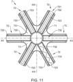
- depicts a top view of the current tab member of
Fig. 10 ; - Fig. 12
- depicts a cross-section of the current tab member of
Fig. 11 along line XII-XII; - Fig. 13
- depicts a cross-section of the current tab member of
Fig. 11 along line XIII-XIII; - Fig. 14
- depicts a cross-section of the current tab member of
Fig. 12 along line XIV-XIV; - Fig. 15
- depicts a bottom portion of the energy storage cell of
Fig. 1 ; - Fig. 16
- depicts a cross-section of the bottom portion of
Fig. 15 along line XVI-XVI; - Fig. 17
- depicts a cross-section of the bottom portion of
Fig. 15 along line XVII-XVII; - Fig. 18
- depicts a cross-section of a variant of the bottom portion; and
- Fig. 19
- depicts a cross-section of a variant of the bottom portion.
- Referring to
Fig. 1 andFig. 2 , an energy storage cell 1 is depicted. The energy storage cell 1 may be configured as asupercapacitor 11. - The energy storage cell 1 may comprise a
cell body 2. Thecell body 2 may have a cylindrical shape. It is also possible for thecell body 2 to be a cuboid shape. Irrespective of the shape the terms radial, axial and circumferential as used herein apply to the cylindrical shape and mutatis mutandis to the other shapes. Thecell body 2 may be formed as an open can. Thecell body 2 is preferably integrally formed as a single unitary member. Thecell body 2 may be formed by impact extrusion or any other suitable forming method. Thecell body 2 may be made of a lightweight metal material, such as aluminium. - The
cell body 2 may comprise abottom portion 21. The bottom portion may be generally disk-shaped. Thebottom portion 21 may be formed as a massive portion without discontinuities. - The
bottom portion 21 may include a plurality ofexterior welding grooves 211. Eachexterior welding groove 211 may be disposed on an exterior surface of the bottom portion. Eachexterior welding groove 211 may extend from a central portion of thebottom portion 21 in a radial direction. Eachexterior welding groove 211 may include awelding groove base 211a, which is recessed with respect to the general surface of thebottom portion 21. Theexterior welding groove 211 may be thinner as adjacent portions in an axial direction. Theexterior welding groove 211 may be the thinnest portion of thebottom portion 21 in the axial direction. - The
bottom portion 21 may include abottom protrusion 212. Thebottom protrusion 212 is preferably disposed on the center portion of thebottom portion 21. Thebottom protrusion 212 may protrude from thebottom portion 21 downward in an axial direction. Thebottom protrusion 212 may have a cylindrical shape. Thebottom protrusion 212 may have other shapes, such as a cuboid shape, or any shape that is suitable for connecting energy storage cells to each other. - The
bottom portion 21 may include abottom fluid passage 213. Thebottom fluid passage 213 may be formed in the center portion of thebottom portion 21. Preferably, thebottom fluid passage 213 is formed within thebottom protrusion 212. - The
cell body 2 may include awall portion 22. Thewall portion 22 may extend upward in the axial direction. Thewall portion 22 may extend along a circumferential direction of thecell body 2, so as to form an open can shape. Thewall portion 22 may have at least onepredetermined breaking portion 221. Thepredetermined breaking portion 221 is configured such that at a predetermined pressure inside thecell body 2, thepredetermined breaking portion 221 structurally fails and releases the pressure from thecell body 2. - The
cell body 2 may include atop opening 23. Thetop opening 23 is preferably defined by thewall portion 22. Thetop opening 23 is preferably circularly shaped. - The
cell body 2 may include aplug member 24. Theplug member 24 may be inserted into thebottom fluid passage 213. Preferably, theplug member 24 is welded to thebottom portion 21. - The
bottom portion 21, thewall portion 22 and thetop opening 23 may define acell interior 25. In other words, thecell interior 25 is that volume of thecell body 2 that, when thetop opening 23 is closed, e.g. by a lid, is inside thecell body 2. - Referring to
Fig. 2 andFig. 9 , anelectrode assembly 3 is depicted. Theelectrode assembly 3 can be any electrode assembly that is typically used for supercapacitors. For example, theelectrode assembly 3 may be a wound electrode assembly that has both the anode and the cathode wound up into a coil, wherein the electrodes are separated by a separator. At least one of the electrodes may comprise a microporous carbon material as part of an active material. - The
electrode assembly 3 may include an insulatingmember 31 that is arranged towards the top of theelectrode assembly 3. The insulatingmember 31 is configured for partial electrical insulation of theelectrode assembly 3. - The
electrode assembly 3 may include afixation member 33 that holds the windings of theelectrode assembly 3 together. The insulatingmember 31 and thefixation member 33 may be configured as an adhesive tape. Theelectrode assembly 3 is disposed in thecell interior 25. - The energy storage cell 1 may include an
electrolyte 4. Theelectrolyte 4 can be any suitable electrolyte used in supercapacitors. Theelectrolyte 4 is also arranged within thecell interior 25. - The energy storage cell 1 may comprise a lid assembly 5. The lid assembly 5 can be inserted through the
top opening 23 such that thecell interior 25 is closed off from the outside of thecell body 2. The lid assembly 5 can be fixed to thewall portion 22, preferably by welding. - Referring to
Fig. 2 to Fig. 5 , the lid assembly 5 may include alid member 51. Thelid member 51 is generally a flat extended member that is suitable to be inserted into thetop opening 23. As depicted here, thelid member 51 is generally disk-shaped. - The
lid member 51 may include a firstexpansion chamber portion 511. The firstexpansion chamber portion 511 is formed in thelid member 51. The firstexpansion chamber portion 511 may include achamber top portion 511a, which is preferably partially formed by alid base portion 512. - The first
expansion chamber portion 511 may include afirst support protrusion 511b. Thefirst support protrusion 511b may be arranged on an outer rim portion. Thefirst support protrusion 511b may protrude from thechamber top portion 511a axially downward. Thefirst support protrusion 511b preferably extends along the whole circumferential direction along the outer rim portion. - The first
expansion chamber portion 511 may include asecond support protrusion 511c. Thesecond support protrusion 511c may protrude from thechamber top portion 511a axially downward. Thesecond support protrusion 511c may be recessed relative to thefirst support protrusion 511b along the axial direction. In other words, thesecond support protrusion 511c need not extend as far downward as thefirst support protrusion 511b. Thesecond support protrusion 511c may be arranged radially closer to the center portion of thelid member 51 than thefirst support protrusion 511b. - The
lid member 51 may include alid base portion 512. Thelid base portion 512 is generally a flat portion. As depicted here, thelid base portion 512 has roughly a disk-shape. - The
lid member 51 may include alid opening 513. Thelid opening 513 is preferably arranged on the center portion of thelid base portion 512. Thelid opening 513 may include a circumferentialvertical wall 513a. The circumferentialvertical wall 513a may extend in an axial direction. The circumferentialvertical wall 513a may be configured as avertical sealing surface 513b for forming a seal. - The
lid opening 513 may further include a taperedcircumferential wall 513c. The taperedcircumferential wall 513c may begin at the bottom of thecircumferential wall 513a. The taperedcircumferential wall 513c may increase in diameter downward in the axial direction. The taperedcircumferential wall 513c may be configured as atapered sealing surface 513d for forming a seal. - The
lid member 51 may further include areinforcement structure 514. Thereinforcement structure 514 may be formed on an inward side of thelid base portion 512 so as to face thecell interior 25. Thereinforcement structure 514 may include a plurality ofribs 514a. Therib 514a may extend between thefirst support protrusion 511b and thesecond support protrusion 511c. Therib 514a may extend along thechamber top portion 511a. - The
lid member 51 may include alid welding groove 515. Thelid welding groove 514 may be arranged on a top surface of thelid member 51. Thelid welding groove 515 may be formed within thelid base portion 512. Thelid welding groove 514 may be arranged on an outside surface of thelid base portion 512. Thelid welding groove 515 may extend along a circumferential direction. Thelid welding groove 515 may be formed on an outer rim portion of thelid member 51. - The
lid welding groove 515 may include a plurality of groove sidewalls 515a. Thelid welding groove 515 may further include awelding surface 515b. Thewelding surface 515b may extend along the radially outermost circumferential surface of thelid member 51. Thewelding surface 515b may extend along an axial direction. Thewelding surface 515b may extend around the whole circumference of thelid member 51. - Referring to
Fig. 2 andFig. 6 toFig. 8 , a sealingmember 52 is depicted. The sealingmember 52 may include a secondexpansion chamber portion 521. The secondexpansion chamber portion 521 is configured to match with the firstexpansion chamber portion 511. - The second
expansion chamber portion 521 may include achamber bottom portion 521a. The secondexpansion chamber portion 521 may include afirst sealing groove 521b. Thefirst sealing groove 521b may face axially upward from thechamber bottom portion 521a. Sidewalls of thefirst sealing groove 521b may protrude axially upward. Thefirst sealing groove 521b may be arranged on an outer rim portion of the sealingmember 52. Thefirst sealing groove 521b preferably extends along the entire circumference of the sealingmember 52. - The second
expansion chamber portion 521 may include asecond sealing groove 521c. Thesecond sealing groove 521c may be formed radially closer to the center portion of the sealingmember 52 than thefirst sealing groove 521b. Thefirst sealing groove 521b and thesecond sealing groove 521c may form sidewalls of the secondexpansion chamber portion 521. Thechamber bottom portion 521a may form a base of the secondexpansion chamber portion 521. - The sealing
member 52 may include asealing base portion 522. The sealingbase portion 522 may include at least onefluid opening 522a. Thefluid opening 522a is preferably arranged on the secondexpansion chamber portion 521. Thefluid opening 522a is preferably disposed on thechamber bottom portion 521a. - The sealing
member 52 may include asealing opening 523. The sealingopening 523 is preferably formed in the center portion of the sealingmember 52. The sealingopening 523 may include acircumferential sidewall 523a. Thecircumferential sidewall 523a may extend in the axial direction. - The sealing
opening 523 may include a sealingshroud 523b. The sealingshroud 523b may protrude from thecircumferential sidewall 523a upward in the axial direction. The sealingshroud 523b may have a smaller radial thickness compared to thecircumferential sidewall 523a. - The sealing
opening 523 may include atapered sealing portion 523c. The taperedsealing portion 523c may be formed adjacent to thecircumferential sidewall 523a. The taperedsealing portion 523c may face away from the sealingshroud 523b. The taperedsealing portion 523c may expand downward in the axial direction. - The sealing
opening 523 may include abead sealing portion 523d. Thebead sealing portion 523d is preferably arranged at the transition between thecircumferential sidewall 523a and the sealingshroud 523b. Thebead sealing portion 523d may face axially upward. Thebead sealing portion 523d, along the radial direction, may be interposed between thesecond sealing groove 521c and thecircumferential sidewall 523a. - The sealing
opening 523 may comprise secondbead sealing portion 523e. The secondbead sealing portion 523e may be arranged at the transition between thecircumferential sidewall 523a and the tapered sealingportion 523c. The secondbead sealing portion 523e may face downward in the axial direction. The secondbead sealing portion 523e, along the radial direction, may be arranged at the same position as thecircumferential sidewall 523a and/or the sealingshroud 523b. In other words, the secondbead sealing portion 523e may be aligned with thecircumferential sidewall 523a and/or with the sealingshroud 523b along the axial direction. - The sealing
member 52 may include awiper portion 524. Thewiper portion 524 may be formed on the outermost circumferential surface of the sealingmember 52. Thewiper portion 524 may include a plurality of protrusions and recesses that are alternatingly arranged along the axial direction. - The lid assembly 5 may further include an insulating
part 53 that is arranged outside thecell interior 25 and in contact with thelid member 51. - Referring again to
Fig. 1 andFig.2 , the energy storage cell 1 includes anexpansion chamber 6. Theexpansion chamber 6 is interposed between thelid member 51 and the sealingmember 52. Theexpansion chamber 6 is formed by the cooperation of the firstexpansion chamber portion 511 and the secondexpansion chamber portion 521. Theexpansion chamber 6 is fluidly connected to thecell interior 25 via thefluid openings 522a. - Referring to
Fig. 2 andFig. 9 toFig. 14 , acurrent tab member 7 is depicted. Thecurrent tab member 7 may include aterminal portion 71. Theterminal portion 71 may be arranged at a center portion of thecurrent tab member 7. Theterminal portion 71 may be formed such that theterminal portion 71 can be inserted into the sealingopening 523. Theterminal portion 71 may be formed such that theterminal portion 71 can protrude through thelid opening 513. Theterminal portion 71 may have a height such that in an installed position, theterminal portion 71 protrudes from thelid member 51. - The
current tab member 7 may include at least one contactingportion 72. The contactingportion 72 may extend in a radial direction. The contactingportion 72 may extend from the center portion of thecurrent tab member 7. - The contacting
portion 72 may include atab welding portion 721. Thetab welding portion 721 is configured for welding thecurrent tab member 7 to theelectrode assembly 3. The contactingportion 72 may include atab welding groove 722. Thetab welding groove 722 may have thetab welding portion 721 as its base. As specifically depicted inFig. 11 , thetab welding portion 721 is welded to theelectrode assembly 3 via atab weld seam 723. - Multiple configurations of tab weld seams 723 are possible. For example, the
tab weld seam 723 may be formed by two separate weld seams that are arranged parallel to each other along thetab welding portion 721. - In another configuration, the
tab weld seam 723 may be a continuous weld seam that is longer that the longitudinal dimension of thetab welding portion 721. For example, thetab weld seam 723 may start on the radial outside, move radially inward to the center portion, then change direction along the circumferential direction or a tangent to the circumferential direction and again move outwards from the center portion to the outer rim portion of thetab welding portion 721. - It is also possible to have the
tab weld seam 723 configured in the opposite, i.e. the circumferential part or the tangential part are performed on the radial outward portion and not close to the center portion. It is also possible to combine these so as to form a rectangulartab weld seam 723. - In another configuration, the
tab weld seam 723 can be zigzag configuration that alternates between both sidewalls of thetab welding groove 722. It should be noted that the straight line zigzag configuration is not the only possible embodiment; it is also possible to form thetab weld seam 723 in an alternating manner by making a sine curve or any other suitable continuous oscillating movement. - The
current tab member 7 may include aheat sink portion 73. Theheat sink portion 73 may be arranged at the center portion of the current tab member. Theheat sink portion 73 is preferably disposed so as to support theterminal portion 71. In other words, theterminal portion 71 is adjacent to theheat sink portion 73 in the axial direction. Theheat sink portion 73 has a larger thickness in the radial direction compared to theterminal portion 71. - The
heat sink portion 73 may include a taperedheat sink portion 731. The taperedheat sink portion 731 is preferably cone-shaped. The taperedheat sink portion 731 has its smallest extension near theterminal portion 71 and expands in radial thickness downward in the axial direction. - The
heat sink portion 73 may include anotch 732. Thenotch 732 may be formed with the taperedheat sink portion 731. Thenotch 732 may be formed such that thetap welding groove 722 can be extended closer to the center portion of thecurrent tab member 7. - The
heat sink portion 73 may include a plurality of thermalconductive leg portions 733. The thermalconductive leg portion 733 may extend from the taperedheat sink portion 731 preferably along the contactingportion 722. The thermalconductive leg portion 733 may form a sidewall of thetab welding groove 722. The thermalconductive leg portion 733 may have a much larger axial thickness (4 to 8 times) compared to the axial thickness of thetab welding portion 721. - Referring to
Fig. 15 to Fig. 17 , thebottom portion 21 is described in more detail. The plurality ofexterior welding grooves 211 may extend from the central portion of thebottom portion 21 towards the periphery. Theexterior welding groove 211 may comprise a plurality of bottom weld seams 211b. Thebottom weld seam 211b may be formed on thewelding groove base 211a. - Similar to the
tab weld seam 723, thebottom weld seam 211b may be formed in two discontinuous parallel parts or a as continuousbottom weld seam 211b that is longer than the longitudinal dimension of theexterior welding groove 211. - In one example, the
bottom weld seam 211b may start at the outer periphery and run substantially parallel to theexterior welding groove 211 and include a circumferential or tangential to the circumference part that is arranged close to the center portion and another part that extends from the center portion back towards the periphery. - In another example, the
bottom weld seam 211b may begin at the center portion and extend substantially parallel to theexterior welding groove 211 followed by a circumferential or tangential to the circumference part that is arranged towards the outer rim and another part that extends from the outer rim back towards the center portion. - In another example, the
bottom weld seam 211b extends in a zigzag formation along theexterior welding groove 211. The zigzag formation may be composed of a plurality of straight paths or a continuously oscillating path, such as a sinusoidal oscillation. - Referring to
Fig. 18 , a variant of thebottom portion 21 is depicted. In this example, theelectrode assembly 3 comprises a bottomcurrent tab member 32 which is fixed to the electrode assembly at an opposite side of thecurrent tab member 7. The bottomcurrent tab member 32 is substantially disk-shaped. The bottomcurrent tab member 32 may include abottom sleeve portion 32a. Thebottom sleeve portion 32a may be formed on a center portion of the bottomcurrent tab member 32. Thebottom sleeve portion 32a is inserted into thebottom fluid passage 213. Thebottom sleeve portion 32a still leaves thebottom fluid passage 213 available for a fluid connection. In other words, thebottom sleeve portion 32a defines an opening that is smaller but still part of thebottom fluid passage 213. In this variant, theplug member 24 is adapted to close thebottom fluid passage 213 by being welded to the bottomcurrent tab member 32, preferably thebottom sleeve portion 32a. - Referring to
Fig. 19 , another variant of thebottom portion 21 does not have any fluid passage that allows a fluid connection between thecell interior 25 and the outside of thecell body 2. In this configuration, thebottom protrusion 212 is a massive portion without discontinuities or openings. - In the following, an embodiment of a method for manufacturing the energy storage cell 1 is described in more detail.
- Initially, a
cell body 2 having at least thebottom portion 21, thewall portion 22 and thetop opening 23 is provided. Theelectrode assembly 3 is inserted into thecell body 2 through thetop opening 23. Theelectrode assembly 3 gets into contact with thebottom portion 21. Theelectrode assembly 3 is welded to thebottom portion 21 by laser welding or ultrasonic welding, for example. The respective laser beam or sonotrode is moved on thewelding groove base 211a such that any of the previously described bottom weld seams 211b are formed. Theelectrode assembly 3 is in electrical contact with thebottom portion 21. - The
cell body 2 and theelectrode assembly 3 are brought to a filling station for theelectrolyte 4. Therein, a vacuum, below 300 mb, preferably from 10 to 100 mb (rough vacuum) is applied. Theelectrolyte 4 is filled through thetop opening 23 into thecell interior 25. Theelectrode assembly 3, as it is typically configured for supercapacitors, includes electrodes having a microporous (carbon) material. Theelectrolyte 4 adsorbs into the micropores, thereby generating adsorption heat which may heat theelectrolyte 4 above boiling point. Theelectrolyte 4 may therefore be added not at once, but in several steps of adding someelectrolyte 4, waiting for a predetermined amount of time and then again adding someelectrolyte 4. It is also possible to cool theelectrolyte 4 before filing. In another example, thecell body 2 is held in a heat sink member and/or actively cooled. Preferably, the cooling (either passively via heat sink or actively) is preferably dimensioned so as to prevent theelectrolyte 4 from boiling and more preferably, from even reaching its flash point (if applicable). - After
enough electrolyte 4 was added to thecell body 2, preferably still under the vacuum, the lid assembly 5 is inserted into thetop opening 23. During insertion of the lid assembly 5, the sealingmember 52, specifically thewiper portion 524, wipes any electrolyte from thewall portion 22 towards thebottom portion 21. As a result, thelid member 51, specifically thewelding surface 515b, makes contact with a part of thewall portion 22 that has been cleaned fromelectrolyte 4 by the lid assembly 5. - During insertion of the lid assembly 5, the
current tab member 7 comes into contact with the sealingmember 52. Specifically, theterminal portion 71 may come into contact with thecircumferential sidewall 523a and the sealingshroud 523b. The sealingshroud 523b electrically insulates theterminal portion 71 from thelid opening 513, specifically from the circumferentialvertical wall 513a. Theterminal portion 71 may exert a pressure onto theceiling shroud 523b and press it against thevertical sealing service 513b in order to form a seal. - Furthermore, the
terminal portion 71 and/or theheat sink portion 73 may come into contact with the secondbead sealing portion 523e. The secondbead sealing portion 523e may be pressed against the current tab member in order to form a seal. - The
heat sink portion 73 may come in contact with the sealingmember 52. Specifically, the taperedheat sink portion 731 may come into contact with the tapered sealingportion 523c. The thermalconductive leg portion 733 may come into contact with the sealingbase portion 522 and/or the secondexpansion chamber portion 521, e.g. thechamber bottom portion 521a. Thefluid openings 522a and the contactingportions 72 are configured such that irrespective of the relative position of thecurrent tab member 7 to the sealingmember 52, an area equivalent to at least onefluid opening 522a allows a fluid connection between thecell interior 25 and theexpansion chamber 6. - The
expansion chamber 6 is formed by bringing thelid member 51 and the sealingmember 52 into contact with each other. In this configuration, thefirst support protrusion 511b is accommodated in thefirst sealing groove 521b. Furthermore, thesecond support protrusion 511c may be accommodated in thesecond sealing groove 521c. As a result, theexpansion chamber 6 is formed cooperatively by thelid member 51 and sealingmember 52. Theexpansion chamber 6 may be defined by thechamber top portion 511a, thefirst support protrusion 511b, thefirst sealing groove 521b, thechamber bottom portion 521a, thesecond sealing groove 521c and thesecond support protrusion 511c. Theexpansion chamber 6 is formed such that thefluid opening 522a allows for fluid to be received from the cell interior or discharged from theexpansion chamber 6 into the cell interior. - The lid assembly 5 is fixed to the
cell body 2 by welding. Specifically, thelid member 51 may be welded to thewall portion 22 by laser welding. Preferably, the welding laser is directed parallel to the axial direction and onto the boundary between thewelding surface 515b and an inner surface of thewall portion 22. With this, thecell body 2 is closed off by the lid assembly 5 against the environment and the energy storage cell 1 is completed. In contrast to the known manufacturing methods, theelectrolyte 4 may be filled into thecell body 2 faster, even if the electrode assembly is already inserted into thecell body 2. In addition, fire hazards may be avoided, due to theelectrolyte 4 being removed from close to the welding surfaces of the lid assembly 5 by the lid assembly itself. Overall, the handling of theelectrolyte 4 is simplified and the overall time for manufacturing a single energy storage cell 1 may be reduced with the measures described above. In contrast to batteries, the microporous nature of theelectrode assembly 3 or more specifically, the much larger amount of microporous material compared to regular secondary batteries, makes it much more difficult to introduce theelectrolyte 4 at a high rate. With the previously described measures, the filling time for theelectrolyte 4 may be substantially reduced. - Subsequently, another example for manufacturing the energy storage cell 1 is described in more detail.
- Initially, a cell body is provided. The cell body includes at least the
bottom portion 21, thewall portion 22 and thetop opening 23. Furthermore, thebottom portion 21 includes thebottom fluid passage 213. - In a next step, the
electrode assembly 3 is inserted into thecell interior 25 and welded to thebottom portion 21, as previously described. Furthermore, the lid assembly 5 is inserted into thetop opening 23 to close off the cell interior 25 from the environment. The lid assembly 5 is welded to thecell body 2, specifically, to thewall portion 22, as previously described. - This results in a
cell body 2 where the only opening left is thebottom fluid passage 213. - This arrangement is brought into a filling station, where a vacuum (as described above) is applied. The
cell body 2 may be held in heat sink member and/or be actively cooled. Furthermore, theelectrolyte 4 may be cooled before and/or during filling. - Subsequently, an injection member is inserted through the
bottom fluid passage 213 and injects theelectrolyte 4 into the cell interior. At the same time, the injection member may include a venting member that allows removal of vapors, gases, or other fluids from the cell interior. Theelectrolyte 4 is inserted so as to wet theelectrode assembly 3. Finally, the injection member is removed and theplug member 24 is inserted into thebottom fluid passage 213. Aplug member 24 is welded to thebottom portion 21, thereby closing off thecell interior 25 towards the bottom and completing the energy storage cell 1. - Similarly as before, during injection of the
electrolyte 4, adsorption heat is generated. The heat is removed via cooling thecell body 2 using a heat sink and/or active cooling. Additionally or alternatively, the electrolyte itself may be cooled before injection. It is also possible to keep cooling the cell body and its contents after filling in order to ensure that theelectrolyte 4 does not boil off. - In case boiling of the
electrolyte 4 cannot be prevented, the vapors may rise inside the cell interior and expand into theexpansion chamber 6. Thereby relieving pressure from the cell body and containing the electrolyte vapors inside thecell interior 25. - As a result, this type of cell may also be filled faster with
electrolyte 4 compared to the known methods. In addition, the configuration ensures that, even if boiling of theelectrolyte 4 cannot be prevented, theelectrolyte 4 is still contained in the cell interior and the pressure relieved such that thecell body 2 is still sealed. - Subsequently, a functioning of the energy storage cell 1 during a failure, such as short-circuit or during high load is described in more detail.
- When the energy storage cell 1 is heated during a high load cycle, the
electrolyte 4 may partially transition into gas form. Sometimes, theelectrolyte 4 is already above flash point temperature and may therefore generated explosive atmospheres. The electrolyte vapors can move from theelectrode assembly 3 through thecell interior 25 and passing thecurrent tab member 7 through thefluid opening 522a into theexpansion chamber 6, where they can be easily contained. Thus, rise of a pressure of thecell interior 25 up to a point where thepredetermined breaking portion 221 breaks, can be avoided. - In case of a short-circuit, a large amount of heat is generated within the
cell interior 25. Theelectrolyte 4 behaves as previously described and may go into theexpansion chamber 6, thereby avoiding a burst pressure of the predetermined breaking portion 221.In addition, the comparatively thickbottom portion 21 can act as a heat sink. - Also, due to the special configuration of the current tab member, heat generated in the electrode assembly is easily conducted by the thermal
conductive leg portions 733 towards the taperedheat sink portion 731 and theadjacent terminal portion 71. - Simulations of the applicant show that in the short-circuit case, the highest thermal load in the energy storage cell is present on the
current tab member 7 and thebottom portion 21, specifically, thebottom protrusion 212. Although a substantial amount of energy can be stored in the energy storage cell, the temperature of these portions does not exceed 100°C. Furthermore, the simulations show that the temperature in the largest portion of the cell interior is well below 50°C and thus usually below the boiling point of theelectrolyte 4. Consequently, the energy storage cell 1 as previously described is also more resilient against higher loads and short-circuits compared to conventional cells. -
- 1
- energy storage cell
- 11
- supercapacitor
- 2
- cell body
- 21
- bottom portion
- 211
- exterior welding groove
- 211a
- welding groove base
- 211b
- bottom weld seam
- 212
- bottom protrusion
- 213
- bottom fluid passage
- 22
- wall portion
- 221
- predetermined breaking portion
- 23
- top opening
- 24
- plug member
- 25
- cell interior
- 3
- electrode assembly
- 31
- insulating member
- 32
- bottom current tab member
- 32a
- bottom sleeve portion
- 33
- fixation member
- 4
- electrolyte
- 5
- lid assembly
- 51
- lid member
- 511
- first expansion chamber portion
- 511a
- chamber top portion
- 511b
- first support protrusion
- 511c
- second support protrusion
- 512
- lid base portion
- 513
- lid opening
- 513a
- circumferential vertical wall
- 513b
- vertical sealing surface
- 513c
- tapered circumferential wall
- 513d
- tapered sealing surface
- 514
- reinforcement structure
- 514a
- rib
- 515
- lid welding groove
- 515a
- groove sidewall
- 515b
- welding surface
- 52
- sealing member
- 521
- second expansion chamber portion
- 521a
- chamber bottom portion
- 521b
- first sealing groove
- 521c
- second sealing groove
- 522
- sealing base portion
- 522a
- fluid opening
- 523
- sealing opening
- 523a
- circumferential sidewall
- 523b
- sealing shroud
- 523c
- tapered sealing portion
- 523d
- bead sealing portion
- 523e
- second bead sealing portion
- 524
- wiper portion
- 53
- insulating part
- 6
- expansion chamber
- 7
- current tab member
- 71
- terminal portion
- 72
- contacting portion
- 721
- tab welding portion
- 722
- tab welding groove
- 723
- tab weld seam
- 73
- heat sink portion
- 731
- tapered heat sink portion
- 732
- notch
- 733
- thermal conductive leg portion
Claims (15)
- A method for manufacturing a supercapacitor (11) for storing electrical energy, the method comprising:a) providing a cell body (2) that has a bottom portion (21), a wall portion (22), and a top opening (23), wherein the cell body (2) is integrally formed as a single unitary member, and the bottom portion (21) has provided therein a bottom fluid passage (213);b) inserting through the top opening (23) an electrode assembly (3) that has a negative electrode and a positive electrode, and the electrodes are separated by a separator, preferably each electrode including an active material, e.g. a carbon material, that includes micropores;c) fixing the electrode assembly (3) to the bottom portion (21) in an electrically conductive manner;d) closing the top opening (23) with a lid assembly (5) thereby forming a cell interior (25) that contains the electrode assembly (3) in a dry state, and fixing the lid assembly (5) to the cell body (2);e) orienting the cell body (2) such that the bottom fluid passage (213) is facing downward in a vertical direction;f) injecting an electrolyte (4) through the bottom fluid passage (213) such that the electrode assembly (3) gets wetted by the electrolyte (4);g) closing the bottom fluid passage (213) with a plug member (24) and fixing the plug member (24) to the bottom portion (21), thereby obtaining the supercapacitor (11).
- The method according to claim 1, wherein the steps d), e) and f) are performed in the order d) - e) - f) or in the order e) - f) - d).
- The method according to any of the preceding claims, wherein at least step f) is performed under vacuum.
- The method according to any of the preceding claims, wherein in step a) the bottom portion (21) is provided with a bottom protrusion (212) that protrudes outside the cell body (2) in an axial direction, and the bottom fluid passage (213) is formed on the bottom protrusion (212).
- The method according to any of the preceding claims, wherein step b) comprises welding a current tab member (7) to the electrode assembly (3) and/or the electrode assembly (3) has a current tab member (7) welded thereon before inserting the electrode assembly (3) with the current tab member (7) facing away from the bottom portion (21).
- The method according to any of the preceding claims, wherein step b) comprises welding a bottom current tab member (32) to the electrode assembly (3) and/or the electrode assembly (3) has a bottom current tab member (32) welded thereon before inserting the electrode assembly (3) with the bottom current tab member (32) contacting the bottom portion (21).
- The method according to claim 6, wherein in step c) the bottom current tab member (32) is welded to the bottom portion (21).
- The method according to any of the preceding claims, wherein step f) comprises cooling the electrolyte (4) before and/or during injecting of the electrolyte (4); and/or cooling the electrolyte (4) for a predetermined amount of time after injecting of the electrolyte (4).
- The method according to any of the preceding claims, wherein step f) comprises contacting the cell body (2) and/or the electrode assembly (3) with a heat sink before and/or during injecting of the electrolyte (4); and/or contacting the cell body (2) and/or the electrode assembly (3) for a predetermined amount of time after injecting of the electrolyte (4).
- The method according to any of the preceding claims, wherein step f) comprises cooling the cell body (2) and/or the electrode assembly (3) before and/or during injecting of the electrolyte (4); and/or the cell body (2) and/or the electrode assembly (3) for a predetermined amount of time after injecting of the electrolyte (4).
- The method according to any of the claims 8 to 10, wherein in step f) cooling is performed such that the electrolyte (4) is prevented from boiling and/or wherein in step f) cooling is performed such that the electrolyte (4) is kept below its flash point.
- The method according to any of the preceding claims, wherein in step g) the plug member (24) is fixed by welding to the bottom portion (21) and/or the bottom current tab member (32).
- The method according to claim 12, wherein step g) comprises laser welding the plug member (24) to the bottom portion (21) and/or the bottom current tab member (32).
- The method according to claim 13, wherein the laser beam is directed parallel to the wall portion (22) so as to impinge on a boundary area between the plug member (24) and the bottom portion (21) and/or the bottom current tab member (32).
- A supercapacitor (11), obtainable by a method according to any of the preceding claims.
Applications Claiming Priority (3)
| Application Number | Priority Date | Filing Date | Title |
|---|---|---|---|
| DE102021134619 | 2021-12-23 | ||
| DE102022100863.0A DE102022100863A1 (en) | 2021-12-23 | 2022-01-14 | Method of manufacturing an energy storage cell |
| EP22211818.4A EP4202962A1 (en) | 2021-12-23 | 2022-12-06 | A method for manufacturing a supercapacitor |
Related Parent Applications (1)
| Application Number | Title | Priority Date | Filing Date |
|---|---|---|---|
| EP22211818.4A Division EP4202962A1 (en) | 2021-12-23 | 2022-12-06 | A method for manufacturing a supercapacitor |
Publications (2)
| Publication Number | Publication Date |
|---|---|
| EP4539216A2 true EP4539216A2 (en) | 2025-04-16 |
| EP4539216A3 EP4539216A3 (en) | 2025-12-10 |
Family
ID=84367207
Family Applications (5)
| Application Number | Title | Priority Date | Filing Date |
|---|---|---|---|
| EP25161410.3A Pending EP4539216A3 (en) | 2021-12-23 | 2022-12-06 | A method for manufacturing a supercapacitor |
| EP22211818.4A Pending EP4202962A1 (en) | 2021-12-23 | 2022-12-06 | A method for manufacturing a supercapacitor |
| EP25162325.2A Pending EP4542739A3 (en) | 2021-12-23 | 2022-12-06 | A current tab member for an electrode assembly of an energy storage cell, kit-of-parts and energy storage cell comprising the current tab member |
| EP25162322.9A Pending EP4542738A3 (en) | 2021-12-23 | 2022-12-06 | A lid assembly for an energy storage cell, kit-of-parts and energy storage cell comprising the lid assembly |
| EP22835613.5A Pending EP4453980A1 (en) | 2021-12-23 | 2022-12-09 | A method for manufacturing an energy storage cell |
Family Applications After (4)
| Application Number | Title | Priority Date | Filing Date |
|---|---|---|---|
| EP22211818.4A Pending EP4202962A1 (en) | 2021-12-23 | 2022-12-06 | A method for manufacturing a supercapacitor |
| EP25162325.2A Pending EP4542739A3 (en) | 2021-12-23 | 2022-12-06 | A current tab member for an electrode assembly of an energy storage cell, kit-of-parts and energy storage cell comprising the current tab member |
| EP25162322.9A Pending EP4542738A3 (en) | 2021-12-23 | 2022-12-06 | A lid assembly for an energy storage cell, kit-of-parts and energy storage cell comprising the lid assembly |
| EP22835613.5A Pending EP4453980A1 (en) | 2021-12-23 | 2022-12-09 | A method for manufacturing an energy storage cell |
Country Status (3)
| Country | Link |
|---|---|
| EP (5) | EP4539216A3 (en) |
| DE (1) | DE102022132405A1 (en) |
| WO (1) | WO2023117487A1 (en) |
Families Citing this family (7)
| Publication number | Priority date | Publication date | Assignee | Title |
|---|---|---|---|---|
| EP4383301A3 (en) * | 2022-11-09 | 2024-08-07 | Skeleton Technologies GmbH | Process for manufacturing a supercapacitor, in particular electrolyte injection |
| DE102022132406A1 (en) * | 2022-12-06 | 2024-06-06 | Skeleton Technologies GmbH | Current collector element for an electrode assembly of an energy storage cell, kit and energy storage cell with the current collector element |
| DE102022132404A1 (en) * | 2022-12-06 | 2024-06-06 | Skeleton Technologies GmbH | Cover assembly for an energy storage cell, kit and energy storage cell with the cover assembly |
| EP4507070A1 (en) * | 2023-08-07 | 2025-02-12 | Skeleton Technologies GmbH | Thermal management assembly for an energy storage cell and energy storage cell equipped therewith |
| EP4507078A1 (en) * | 2023-08-07 | 2025-02-12 | Skeleton Technologies GmbH | Current tab assembly for an energy storage cell and energy storage cell equipped therewith |
| WO2025233244A1 (en) | 2024-05-08 | 2025-11-13 | Skeleton Technologies GmbH | Methods for manufacturing an ultracapacitor with improved energy density |
| EP4664498A1 (en) | 2024-06-11 | 2025-12-17 | Skeleton Technologies GmbH | A method for welding at least one cell component to an electrode assembly of an energy storage cell |
Citations (5)
| Publication number | Priority date | Publication date | Assignee | Title |
|---|---|---|---|---|
| FR1439148A (en) | 1965-04-06 | 1966-05-20 | Thomson Houston Comp Francaise | Improvements to waterproof enclosures for electrical devices |
| US20030086239A1 (en) | 2001-11-02 | 2003-05-08 | Maxwell Electronic Components Group, Inc., A Delaware Corporation | Electrochemical double layer capacitor having carbon powder electrodes |
| EP1642894A1 (en) | 2003-07-01 | 2006-04-05 | Otsuka Chemical Company, Limited | Quaternary ammonium salt, electrolyte, and electrochemical device |
| EP1756843A1 (en) | 2004-06-11 | 2007-02-28 | Batscap | Supercapacitor cover with integrated center terminal |
| CN104795257A (en) | 2012-08-28 | 2015-07-22 | 苏州工业园区和顺电气股份有限公司 | Power capacitor immersion treatment method |
Family Cites Families (21)
| Publication number | Priority date | Publication date | Assignee | Title |
|---|---|---|---|---|
| DE1105065B (en) | 1956-11-23 | 1961-04-20 | Sueddeutscher Kondensatorenbau | Electric capacitor in a housing that consists of two separate rooms |
| JP2577818Y2 (en) | 1992-02-14 | 1998-08-06 | ニチコン株式会社 | Electrolytic capacitor |
| JP3598548B2 (en) * | 1994-11-10 | 2004-12-08 | いすゞ自動車株式会社 | Multilayer electric double layer capacitors |
| JP2002141099A (en) | 2000-10-31 | 2002-05-17 | Sanyo Electric Co Ltd | Sealed battery |
| JP3709197B2 (en) * | 2003-08-25 | 2005-10-19 | 松下電器産業株式会社 | Cylindrical battery and manufacturing method thereof |
| CN104064362A (en) * | 2005-09-22 | 2014-09-24 | 本田技研工业株式会社 | Polarizable Electrode And Electrical Double Layer Capacitor |
| JP5034204B2 (en) * | 2005-09-29 | 2012-09-26 | パナソニック株式会社 | Method for manufacturing power storage element |
| KR100786871B1 (en) * | 2006-07-27 | 2007-12-20 | 삼성에스디아이 주식회사 | Secondary battery |
| KR100882915B1 (en) * | 2007-07-03 | 2009-02-10 | 삼성에스디아이 주식회사 | Secondary battery |
| JP2009211909A (en) * | 2008-03-04 | 2009-09-17 | Panasonic Corp | Battery, battery pack, and method of manufacturing connection terminals used therefor |
| US8147999B2 (en) * | 2008-06-11 | 2012-04-03 | Eveready Battery Company, Inc. | Closure assembly with low vapor transmission for electrochemical cell |
| KR101839158B1 (en) * | 2009-10-13 | 2018-03-15 | 파워지닉스 시스템즈, 인코포레이티드 | Cylindrical Nickel-Zinc Cell with Positive Can |
| JP2011204724A (en) | 2010-03-24 | 2011-10-13 | Hitachi Aic Inc | Electrolytic capacitor |
| US8488301B2 (en) * | 2011-02-28 | 2013-07-16 | Corning Incorporated | Ultracapacitor package design having slideably engagable bent tabs |
| KR102762495B1 (en) * | 2012-02-24 | 2025-02-05 | 패스트캡 시스템즈 코포레이션 | Advanced electrolyte systems and their use in energy storage devices |
| CN202796465U (en) * | 2012-09-13 | 2013-03-13 | 江苏集盛星泰新能源科技有限公司 | Super capacitor with positive electrode and negative electrode at same end |
| US9293268B2 (en) * | 2013-11-22 | 2016-03-22 | Corning Incorporated | Ultracapacitor vacuum assembly |
| WO2015146078A1 (en) * | 2014-03-28 | 2015-10-01 | 三洋電機株式会社 | Cylindrical sealed battery and battery pack |
| CN204216139U (en) * | 2014-10-30 | 2015-03-18 | 欧可行 | Energy storage device |
| WO2017201173A1 (en) * | 2016-05-20 | 2017-11-23 | Avx Corporation | Nonaqueous electrolyte for an ultracapacitor |
| EP4037076A4 (en) * | 2019-09-26 | 2023-03-08 | Panasonic Intellectual Property Management Co., Ltd. | Power storage pack |
-
2022
- 2022-12-06 EP EP25161410.3A patent/EP4539216A3/en active Pending
- 2022-12-06 EP EP22211818.4A patent/EP4202962A1/en active Pending
- 2022-12-06 EP EP25162325.2A patent/EP4542739A3/en active Pending
- 2022-12-06 DE DE102022132405.2A patent/DE102022132405A1/en active Pending
- 2022-12-06 EP EP25162322.9A patent/EP4542738A3/en active Pending
- 2022-12-09 WO PCT/EP2022/085171 patent/WO2023117487A1/en not_active Ceased
- 2022-12-09 EP EP22835613.5A patent/EP4453980A1/en active Pending
Patent Citations (5)
| Publication number | Priority date | Publication date | Assignee | Title |
|---|---|---|---|---|
| FR1439148A (en) | 1965-04-06 | 1966-05-20 | Thomson Houston Comp Francaise | Improvements to waterproof enclosures for electrical devices |
| US20030086239A1 (en) | 2001-11-02 | 2003-05-08 | Maxwell Electronic Components Group, Inc., A Delaware Corporation | Electrochemical double layer capacitor having carbon powder electrodes |
| EP1642894A1 (en) | 2003-07-01 | 2006-04-05 | Otsuka Chemical Company, Limited | Quaternary ammonium salt, electrolyte, and electrochemical device |
| EP1756843A1 (en) | 2004-06-11 | 2007-02-28 | Batscap | Supercapacitor cover with integrated center terminal |
| CN104795257A (en) | 2012-08-28 | 2015-07-22 | 苏州工业园区和顺电气股份有限公司 | Power capacitor immersion treatment method |
Also Published As
| Publication number | Publication date |
|---|---|
| WO2023117487A1 (en) | 2023-06-29 |
| EP4542739A2 (en) | 2025-04-23 |
| EP4539216A3 (en) | 2025-12-10 |
| EP4542738A3 (en) | 2025-07-02 |
| EP4202962A1 (en) | 2023-06-28 |
| DE102022132405A1 (en) | 2024-06-06 |
| EP4542739A3 (en) | 2025-07-09 |
| EP4542738A2 (en) | 2025-04-23 |
| EP4453980A1 (en) | 2024-10-30 |
Similar Documents
| Publication | Publication Date | Title |
|---|---|---|
| EP4539216A2 (en) | A method for manufacturing a supercapacitor | |
| CN101916876B (en) | Method and design for externally applied laser welding of internal connections in a high power electrochemical cell | |
| EP4024574B1 (en) | Laser welded lithium-ion button cell battery comprising a top plate | |
| JP6755183B2 (en) | Lithium electrochemical storage batteries with terminals directly attached to the electrochemical assembly and related manufacturing methods | |
| KR100648731B1 (en) | Secondary Battery and Manufacturing Method Thereof | |
| KR102462857B1 (en) | Cylindrical Battery Having no Beading Part and Method For Manufacturing Thereof | |
| KR101075879B1 (en) | Process for Preparing Cylindrical Battery to Prevent Deformation of Beading Portion | |
| CN115149165B (en) | Secondary battery | |
| KR20050122682A (en) | Cylindrical li secondary battery and method of fabricating the same | |
| KR20100134511A (en) | Cap assembly of cylindrical secondary battery, and cylindrical secondary battery comprising same | |
| CN119790529A (en) | Cap assembly, energy storage cell, battery module and method for manufacturing cap assembly | |
| KR20250029252A (en) | Energy storage battery and its manufacturing method | |
| KR20260040617A (en) | Battery cell and method of manufacturing the same, battery and electrical device | |
| JP4169470B2 (en) | Sealed battery | |
| KR102555959B1 (en) | Electrochemical energy storage device comprising external connecting terminal | |
| EP4383299A2 (en) | A current tab member for an electrode assembly of an energy storage cell, kit-of-parts and energy storage cell comprising the current tab member | |
| EP4383300A2 (en) | A lid assembly for an energy storage cell, kit-of-parts and energy storage cell comprising the lid assembly | |
| EP4383301A2 (en) | Process for manufacturing a supercapacitor, in particular electrolyte injection | |
| US20240186077A1 (en) | Method for manufacturing a supercapacitor | |
| US20240274942A1 (en) | Power storage device | |
| JP7628100B2 (en) | Battery and method for manufacturing battery | |
| WO2024069291A1 (en) | Cylindrical electrochemical cells and methods of forming the same | |
| EP2985815B1 (en) | Electricity storage element and method for manufacturing electricity storage element | |
| KR101264461B1 (en) | Cap assembly and rechargeable battery using this same and assembly method of cap assembly | |
| KR100658682B1 (en) | Secondary battery |
Legal Events
| Date | Code | Title | Description |
|---|---|---|---|
| PUAI | Public reference made under article 153(3) epc to a published international application that has entered the european phase |
Free format text: ORIGINAL CODE: 0009012 |
|
| STAA | Information on the status of an ep patent application or granted ep patent |
Free format text: STATUS: THE APPLICATION HAS BEEN PUBLISHED |
|
| AC | Divisional application: reference to earlier application |
Ref document number: 4202962 Country of ref document: EP Kind code of ref document: P |
|
| AK | Designated contracting states |
Kind code of ref document: A2 Designated state(s): AL AT BE BG CH CY CZ DE DK EE ES FI FR GB GR HR HU IE IS IT LI LT LU LV MC ME MK MT NL NO PL PT RO RS SE SI SK SM TR |
|
| REG | Reference to a national code |
Ref country code: DE Ref legal event code: R079 Free format text: PREVIOUS MAIN CLASS: H01M0050152000 Ipc: H01G0002080000 |
|
| PUAL | Search report despatched |
Free format text: ORIGINAL CODE: 0009013 |
|
| AK | Designated contracting states |
Kind code of ref document: A3 Designated state(s): AL AT BE BG CH CY CZ DE DK EE ES FI FR GB GR HR HU IE IS IT LI LT LU LV MC ME MK MT NL NO PL PT RO RS SE SI SK SM TR |
|
| RIC1 | Information provided on ipc code assigned before grant |
Ipc: H01G 2/08 20060101AFI20251106BHEP Ipc: H01G 11/74 20130101ALI20251106BHEP Ipc: H01G 11/80 20130101ALI20251106BHEP Ipc: H01G 11/78 20130101ALI20251106BHEP Ipc: H01G 11/82 20130101ALI20251106BHEP Ipc: H01M 50/147 20210101ALI20251106BHEP Ipc: H01M 50/152 20210101ALI20251106BHEP Ipc: H01G 11/18 20130101ALI20251106BHEP |
|
| STAA | Information on the status of an ep patent application or granted ep patent |
Free format text: STATUS: REQUEST FOR EXAMINATION WAS MADE |