EP4539214A1 - Battery - Google Patents
Battery Download PDFInfo
- Publication number
- EP4539214A1 EP4539214A1 EP24193709.3A EP24193709A EP4539214A1 EP 4539214 A1 EP4539214 A1 EP 4539214A1 EP 24193709 A EP24193709 A EP 24193709A EP 4539214 A1 EP4539214 A1 EP 4539214A1
- Authority
- EP
- European Patent Office
- Prior art keywords
- pole
- battery
- sealing part
- sealing
- riveting
- Prior art date
- Legal status (The legal status is an assumption and is not a legal conclusion. Google has not performed a legal analysis and makes no representation as to the accuracy of the status listed.)
- Pending
Links
Images

Classifications
-
- H—ELECTRICITY
- H01—ELECTRIC ELEMENTS
- H01M—PROCESSES OR MEANS, e.g. BATTERIES, FOR THE DIRECT CONVERSION OF CHEMICAL ENERGY INTO ELECTRICAL ENERGY
- H01M50/00—Constructional details or processes of manufacture of the non-active parts of electrochemical cells other than fuel cells, e.g. hybrid cells
- H01M50/10—Primary casings; Jackets or wrappings
- H01M50/147—Lids or covers
- H01M50/148—Lids or covers characterised by their shape
- H01M50/152—Lids or covers characterised by their shape for cells having curved cross-section, e.g. round or elliptic
-
- H—ELECTRICITY
- H01—ELECTRIC ELEMENTS
- H01M—PROCESSES OR MEANS, e.g. BATTERIES, FOR THE DIRECT CONVERSION OF CHEMICAL ENERGY INTO ELECTRICAL ENERGY
- H01M50/00—Constructional details or processes of manufacture of the non-active parts of electrochemical cells other than fuel cells, e.g. hybrid cells
- H01M50/10—Primary casings; Jackets or wrappings
- H01M50/102—Primary casings; Jackets or wrappings characterised by their shape or physical structure
- H01M50/103—Primary casings; Jackets or wrappings characterised by their shape or physical structure prismatic or rectangular
-
- H—ELECTRICITY
- H01—ELECTRIC ELEMENTS
- H01M—PROCESSES OR MEANS, e.g. BATTERIES, FOR THE DIRECT CONVERSION OF CHEMICAL ENERGY INTO ELECTRICAL ENERGY
- H01M50/00—Constructional details or processes of manufacture of the non-active parts of electrochemical cells other than fuel cells, e.g. hybrid cells
- H01M50/10—Primary casings; Jackets or wrappings
- H01M50/172—Arrangements of electric connectors penetrating the casing
- H01M50/174—Arrangements of electric connectors penetrating the casing adapted for the shape of the cells
- H01M50/179—Arrangements of electric connectors penetrating the casing adapted for the shape of the cells for cells having curved cross-section, e.g. round or elliptic
-
- H—ELECTRICITY
- H01—ELECTRIC ELEMENTS
- H01M—PROCESSES OR MEANS, e.g. BATTERIES, FOR THE DIRECT CONVERSION OF CHEMICAL ENERGY INTO ELECTRICAL ENERGY
- H01M50/00—Constructional details or processes of manufacture of the non-active parts of electrochemical cells other than fuel cells, e.g. hybrid cells
- H01M50/10—Primary casings; Jackets or wrappings
- H01M50/183—Sealing members
- H01M50/184—Sealing members characterised by their shape or structure
-
- H—ELECTRICITY
- H01—ELECTRIC ELEMENTS
- H01M—PROCESSES OR MEANS, e.g. BATTERIES, FOR THE DIRECT CONVERSION OF CHEMICAL ENERGY INTO ELECTRICAL ENERGY
- H01M50/00—Constructional details or processes of manufacture of the non-active parts of electrochemical cells other than fuel cells, e.g. hybrid cells
- H01M50/10—Primary casings; Jackets or wrappings
- H01M50/183—Sealing members
- H01M50/186—Sealing members characterised by the disposition of the sealing members
-
- H—ELECTRICITY
- H01—ELECTRIC ELEMENTS
- H01M—PROCESSES OR MEANS, e.g. BATTERIES, FOR THE DIRECT CONVERSION OF CHEMICAL ENERGY INTO ELECTRICAL ENERGY
- H01M50/00—Constructional details or processes of manufacture of the non-active parts of electrochemical cells other than fuel cells, e.g. hybrid cells
- H01M50/10—Primary casings; Jackets or wrappings
- H01M50/183—Sealing members
- H01M50/186—Sealing members characterised by the disposition of the sealing members
- H01M50/188—Sealing members characterised by the disposition of the sealing members the sealing members being arranged between the lid and terminal
-
- H—ELECTRICITY
- H01—ELECTRIC ELEMENTS
- H01M—PROCESSES OR MEANS, e.g. BATTERIES, FOR THE DIRECT CONVERSION OF CHEMICAL ENERGY INTO ELECTRICAL ENERGY
- H01M50/00—Constructional details or processes of manufacture of the non-active parts of electrochemical cells other than fuel cells, e.g. hybrid cells
- H01M50/10—Primary casings; Jackets or wrappings
- H01M50/183—Sealing members
- H01M50/19—Sealing members characterised by the material
- H01M50/193—Organic material
-
- H—ELECTRICITY
- H01—ELECTRIC ELEMENTS
- H01M—PROCESSES OR MEANS, e.g. BATTERIES, FOR THE DIRECT CONVERSION OF CHEMICAL ENERGY INTO ELECTRICAL ENERGY
- H01M50/00—Constructional details or processes of manufacture of the non-active parts of electrochemical cells other than fuel cells, e.g. hybrid cells
- H01M50/50—Current conducting connections for cells or batteries
- H01M50/543—Terminals
- H01M50/545—Terminals formed by the casing of the cells
-
- H—ELECTRICITY
- H01—ELECTRIC ELEMENTS
- H01M—PROCESSES OR MEANS, e.g. BATTERIES, FOR THE DIRECT CONVERSION OF CHEMICAL ENERGY INTO ELECTRICAL ENERGY
- H01M50/00—Constructional details or processes of manufacture of the non-active parts of electrochemical cells other than fuel cells, e.g. hybrid cells
- H01M50/50—Current conducting connections for cells or batteries
- H01M50/572—Means for preventing undesired use or discharge
- H01M50/584—Means for preventing undesired use or discharge for preventing incorrect connections inside or outside the batteries
- H01M50/59—Means for preventing undesired use or discharge for preventing incorrect connections inside or outside the batteries characterised by the protection means
- H01M50/593—Spacers; Insulating plates
-
- Y—GENERAL TAGGING OF NEW TECHNOLOGICAL DEVELOPMENTS; GENERAL TAGGING OF CROSS-SECTIONAL TECHNOLOGIES SPANNING OVER SEVERAL SECTIONS OF THE IPC; TECHNICAL SUBJECTS COVERED BY FORMER USPC CROSS-REFERENCE ART COLLECTIONS [XRACs] AND DIGESTS
- Y02—TECHNOLOGIES OR APPLICATIONS FOR MITIGATION OR ADAPTATION AGAINST CLIMATE CHANGE
- Y02E—REDUCTION OF GREENHOUSE GAS [GHG] EMISSIONS, RELATED TO ENERGY GENERATION, TRANSMISSION OR DISTRIBUTION
- Y02E60/00—Enabling technologies; Technologies with a potential or indirect contribution to GHG emissions mitigation
- Y02E60/10—Energy storage using batteries
Definitions
- the present disclosure relates to a technical field of battery technologies, and in particular, to a battery.
- the pole tends to expand, causing the pole to squeeze the sealing component and other components of the battery.
- the sealing component and other components of the battery are squeezed out of shape, resulting in insulation failure of the battery, and the insulation failure of the battery affects the stability.
- Embodiments of the present disclosure provide a battery, which may improve the technical problem of insulation failure of the battery caused by expansion of the pole.
- Embodiments of the present disclosure provides a battery.
- the battery includes a housing, a pole, and a sealing component.
- the housing includes a lateral wall and an end plate connected to the lateral wall and provided with a first through hole.
- the pole includes a pole connecting part and a pole limiting part.
- the pole connecting part passes through the first through hole, the pole limiting part is provided on a first end of the pole connecting part, and the pole limiting part is located on a side of the end plate close to the lateral wall.
- the sealing component includes a first sealing part and a second sealing part. The first sealing part is arranged around the pole connecting part and located between the pole limiting part and the end plate, and a first end of the second sealing part is connected to the first sealing part.
- the second sealing part is arranged around the pole connecting part, and the second sealing part is interference-fitted with an inner sidewall of the first through hole.
- the first sealing part is provided with at least one recess on a side surface away from the first end of the pole connecting part, and the recess is configured to provide a deformation space when the first sealing part is squeezed.
- the first sealing part of the sealing component is arranged around the pole connecting part and is located between the pole limiting part of the pole and the end plate, and the second sealing part of the sealing part is arranged around the pole connecting part and passes through the first through hole of the housing.
- the at least one recess is provided on a surface of the first sealing part away from the pole connecting part, an arrangement of the recess provides an accommodation space for deformation at the connection between the first sealing part and the second sealing part.
- the first sealing part When the pole expands to squeeze the first sealing part, the first sealing part is first deformed at the recess to relieve compression on the first sealing part due to expansion of the pole, thereby relieving the overall sealing component from directly squeezing other components of the battery, and improving the stability of the battery.
- connection should be understood in a broad sense.
- it may be a fixed connection, a detachable connection, or an integral body; it may be a mechanical connection or an electrical connection; it may be a direct connection or an indirect connection through an intermediary; it may be an internal connection between two elements or an interaction between two elements.
- connection may be a fixed connection, a detachable connection, or an integral body; it may be a mechanical connection or an electrical connection; it may be a direct connection or an indirect connection through an intermediary; it may be an internal connection between two elements or an interaction between two elements.
- a first feature is “above” or “below” a second feature may include direct contact between the first and second features, or may also include that the first and second features are not in direct contact but through additional characteristic contact between them.
- the first feature is "on”, “above”, or “over” the second feature may include that the first feature is directly above and diagonally above the second feature, and the first feature has a horizontal height higher than that of the second feature.
- That the first feature is "under” or “below” the second feature may include that the first feature is directly below and diagonally below the second feature, and the first feature has a horizontal height lower than that of the second feature.
- orientations or positional relationships indicated by the terms “upper”, “lower”, “left”, “right”, “front”, “rear” etc. are based on the orientations or positional relationships illustrated in the drawings, the terms are intended to facilitate description and simplify operation, and are not intended to indicate or imply that the device or element referred to must have a specific orientation, be constructed and operate in a specific orientation, and therefore cannot be construed as a limitation of the present disclosure.
- first and second are used to differentiate in description and have no special meaning.
- the embodiments provide a battery 100.
- the battery 100 includes a housing 10, a pole 20, and a sealing component 30.
- the housing 10 includes a lateral wall 11 and an end plate 12 connected to the lateral wall 11.
- the lateral wall 11 and the end plate 12 are connected to form a hollow housing 10.
- the hollow housing 10 is configured to accommodate a battery cell, and a tab at an end of the battery cell is connected to an adapting piece.
- the end plate 12 is provided with a first through hole 101.
- the first through hole 101 allows the pole 20 to pass from the inside to the outside of the housing 10, so that one end of the pole 20 is connected to the adapting piece 70, and the other end of the pole 20 is located outside the housing 10.
- the housing 10 may be made of aluminum material.
- the housing 10 made of aluminum material has high specific strength, specific modulus, fracture toughness, fatigue strength, and corrosion resistance stability, and has the advantages of light weight and stable molding.
- the lateral wall 11 illustrated in FIG. 1 is cylindrical, and the cylindrical lateral wall 11 and the end plate 12 are connected to form a cylindrical housing 10.
- the lateral wall 11 may also be in the shape of a quadrangular prism, and the quadrangular prism lateral wall 11 and the end plate 12 are connected to form a square housing 10.
- the pole 20 includes a pole connecting part 21 and a pole limiting part 22.
- the pole connecting part 21 passes through the first through hole 101, and the pole limiting part 22 is provided on a first end of the pole connecting part 21.
- the pole limiting part 22 is located in the housing 10.
- the pole limiting part 22 is located on a side of the end plate 12 close to the lateral wall 11.
- a diameter of the pole connecting part 21 ranges from 3.0 mm to 6.5 mm.
- the diameter of the pole connecting part 21 may be specifically 3.0 mm, 3.5 mm, 4.0 mm, 4.5 mm, 5.0 mm, 5.5 mm, 6.0 mm, or 6.5 mm.
- the sealing component 30 includes a first sealing part 31 and a second sealing part 32.
- the first sealing part 31 is provided around the pole connecting part 21, and the first sealing part 31 is located between the pole limiting part 22 and the end plate 12.
- a first end of the second sealing part 32 is connected to the first sealing part 31, and the second sealing part 32 is arranged around the pole connecting part 21.
- the second sealing part 32 passes through the first through hole 101 so that the second sealing part 32 can seal a part of the pole connecting part 21 provided outside the housing 10.
- the second sealing part 32 is interference-fitted with an inner sidewall of the first through hole 101.
- the first sealing part 31 is provided with at least one recess 3101 on a side surface away from the first end of the pole connecting part 21.
- the recess 3101 is configured to provide a deformation space when the first sealing part 31 is squeezed. That is to say, an arrangement of the recess 3101 provides an accommodation space for deformation at the connection between the first sealing part 31 and the second sealing part 32. Therefore, when the pole 20 expands to squeeze the sealing component 30, the sealing component 30 is first deformed at the recess 3101 to relieve the sealing component 30 from directly squeezing other components of the battery 100 being in contact with the sealing component 30 due to the expansion force of the pole 20. For example, directly squeezing a hole wall of the first through hole 101 is relieved, thereby reducing the deformation of the end plate 12 and reducing the impact on the overall sealing of the housing 10, and reducing the impact on the stability of the battery 100.
- the recess 3101 is arranged around an outer periphery of the second sealing part 32. That is, the recess 3101 and the second sealing part 32 are co-centrically arranged, so that the recess 3101 arranged along the outer periphery of the second sealing part 32 accommodates deformation occurring at the connection between the sealing part 31 and the second sealing part 32.
- a plurality of recesses 3101 are arranged at intervals along a circumferential direction of the second sealing part 32.
- a shape of the recesses 3101 may be one of cylindrical, prismatic, and hemispherical.
- the recesses 3101 may be arranged in a regular shape, or may have an irregular shape, so that the plurality of recesses 3101 along the outer periphery of the second sealing part 32 accommodate deformation occurring at the connection between the first sealing part 31 and the second sealing part 32.
- the sealing component 30 may be made of fluororubber material.
- the sealing component 30 made of fluororubber material has good chemical resistance, making the sealing component 30 particularly suitable for sealing of the battery.
- the pole 20 further includes a pole riveting part 23.
- the pole riveting part 23 is provided on a second end of the pole connecting part 21, and the pole riveting part 23 is located on a side of the end plate 12 away from the lateral wall 11.
- the pole 20 of the battery 100 can be connected to the housing 10 of the battery 100 by riveting to ensure a connection strength between the pole 20 and the housing 10.
- the first difference ranges from 0.3 mm to 0.8 mm.
- the first difference may be specifically 0.3 mm, 0.35 mm, 0.4 mm, 0.45 mm, 0.5 mm, 0.55 mm, 0.6 mm, 0.65 mm, 0.7 mm, 0.75 mm, or 0.8 mm.
- a value of the first difference is controlled from 0.3 mm to 0.8 mm to reduce the risk of cracking due to expansion of the pole riveting part 23.
- the battery 100 further includes a riveting component 40.
- the riveting component 40 is at least partially located between the pole riveting part 23 and the end plate 12.
- a surface of the riveting component 40 close to the end plate 12 is provided with a first accommodation groove 401.
- the first end of the second sealing part 32 of the sealing component 30 is connected to the first sealing part 31, and the second end of the second sealing part 32 is accommodated in the first accommodation groove 401.
- the second sealing part 32 is embedded and matched with the first accommodation groove 401 to achieve sealing between the pole 20 and the housing 10 to prevent electrolyte leakage.
- first reserved gap D 1 between the second end of the second sealing part 32 and a bottom wall of the first accommodation groove 401. Based on an arrangement of the first reserved gap D1, the riveting component 40 provides an accommodation space for deformation of the second sealing part 32.
- the second sealing part 32 deforms to fill the accommodation space formed by the riveting component 40 based on the first reserved gap D1, thereby relieving the second sealing part 32 from directly squeezing the riveting component 40 due to any one or a combination of two of the expansion force of the pole connecting part 21 and the expansion force of the pole riveting part 23 of the pole 20, reducing the risk of deformation and cracking of the riveting component 40, and improving the stability of the battery 100.
- the first reserved gap D1 ranges from 0.1 mm to 0.4 mm.
- the first reserved gap D1 may specifically be 0.1 mm, 0.15 mm, 0.2 mm, 0.25 mm, 0.3 mm, 0.35 mm, or 0.4 mm.
- a value of the first reserved gap D1 is controlled from 0.1 mm to 0.4 mm to ensure that when the pole connecting part 21 expands and squeezes the second sealing part 32, the accommodation space formed by the riveting component 40 based on the arrangement of the first reserved gap D1 can accommodate the deformation of the second sealing part 32, so as to release the deformation force generated by the extrusion of the second sealing part 32 and reduce an amount of deformation of the riveting component 40 caused by the deformation force of the second sealing part 32, thereby reducing the risk of cracking due to deformation of the riveting component 40 and improving the stability of the battery 100.
- a surface of the riveting component 40 away from the end plate 12 is provided with a second accommodation groove 402, and the pole riveting part 23 of the pole 20 is accommodated in the second accommodation groove 402 to realize the connection between the pole riveting part 23 and the riveting component 40.
- a depth h1 of the second accommodation groove 402 is greater than a thickness h2 of the pole riveting part 23, preventing the pole riveting part 23 from protruding from the second accommodation groove 402 to the surface of the riveting component 40 away from the end plate 12, and facilitating a connecting component to weld a plurality of batteries 100 so that the plurality of batteries 100 are connected in series, or in parallel, or in series and in parallel to form a battery module.
- a width of the second accommodation groove 402 ranges from 3.4 mm to 7.0 mm, so as to realize a riveting fixation between the riveting component 40 and the pole 20.
- the width of the second accommodation groove 402 should be greater than a diameter of the pole connecting part 21.
- the depth h1 of the second accommodation groove 402 ranges from 0.5 mm to 1.2 mm to form an escape space for the expansion of the pole 20 in a thickness direction of the pole riveting part 23.
- the riveting component 40 provides an accommodation space for the pole riveting part 23 to expand.
- the pole riveting part 23 expands to fill the accommodation space formed by the riveting component 40 based on the second reserved gap D2, relieving the pole riveting part 23 from directly squeeze the riveting component 40 due to expansion force generated by the expansion of the pole riveting part 23, reducing the risk of cracking due to deformation of the riveting component 40, and improving the stability of the battery 100.
- the second reserved gap D2 ranges from 0.25 mm to 0.6 mm.
- the second reserved gap D2 may be specifically 0.25 mm, 0.3 mm, 0.35 mm, 0.4 mm, 0.45 mm, 0.5 mm, 0.55 mm, or 0.6 mm.
- a value of the second reserved gap D2 is controlled from 0.25 mm to 0.6 mm to ensure that when the pole riveting part 23 expands to compress the riveting component 40, the accommodation space formed by the riveting component 40 based on the arrangement of the second reserved gap D2 can accommodate the expansion and deformation of the pole riveting part 23, so as to release the deformation force generated by the expansion of the pole riveting part 23, and reduce an amount of deformation of the riveting component 40 due to the deformation force of the pole riveting part 23, thereby reducing the risk of cracking due to the deformation of the riveting component 40 and increasing the stability of the battery 100.
- the battery 100 further includes an outer insulation component 50.
- the outer insulation component 50 is disposed around the second sealing part 32 and at least partially located between the riveting component 40 and the end plate 12.
- the outer insulation component 50 is provided with a third through hole 501.
- the third through hole 501 and the first through hole 101 are co-centrically arranged.
- the second sealing part 32 penetrates the third through hole 501, and a hole wall of the third through hole 501 is in contact with an outer periphery of the second sealing part 32.
- the outer insulation component 50 is configured to insulate the riveting component 40 and the end plate 12 to ensure an insulation connection between the pole 20 and the housing 10.
- a third accommodation groove 102 is provided on a surface of the end plate 12 close to the outer insulation component 50.
- the third accommodation groove 102 is provided around the outer periphery of the second sealing part 32. Part of the outer insulation component 50 is accommodated in the third accommodation groove 102.
- the third accommodation groove 102 and the first through hole 101 are co-centrically arranged.
- the outer insulation component 50 is embedded and matched with the third accommodation groove 102 to realize the clamping and fixing of the outer insulation component 50 and the end plate 12 and ensure the insulation connection between the pole riveting part 23 and the end plate 12, thereby realizing the pole 20 insulated from the housing 10.
- the battery 100 further includes an inner insulation component 60.
- the inner insulation component 60 is at least partially located between the pole limiting part 22 and the end plate 12.
- the inner insulation component 60 is configured to insulate the end plate 12 and the adapting piece 70.
- the inner insulation component 60 is provided with a second through hole 601.
- the second through hole 601 and the first through hole 101 are co-centrically arranged.
- the first sealing part 31 at least partially passes through the second through hole 601 to ensure the sealing and insulation between the pole 20 and the end plate 12.
- the first sealing part 31 is provided with an accommodating space for deformation based on an arrangement of the third reserved gap D3.
- the first sealing part 31 deforms to fill the accommodation space formed based on the third reserved gap D3, thereby relieving the first sealing part 31 from directly squeeze the inner insulation component 60 due to any one or a combination of two of the expansion force generated by the pole connecting part 21 and the expansion force generated by the pole limiting part 22, thereby reducing the risk of cracking due to deformation of the inner insulation component 60 and improving the stability of the battery 100.
- the third reserved gap D3 ranges from 0.1 mm to 0.4 mm.
- the first reserved gap D1 may be specifically 0.1 mm, 0.15 mm, 0.2 mm, 0.25 mm, 0.3 mm, 0.35 mm, 0.4 mm.
- a value of the third reserved gap D3 is controlled from 0.1 mm to 0.4 mm to ensure that when any one or a combination of two of the pole connecting part 21 and the pole limiting part 22 expands to compress the first sealing part 31, the accommodation space formed by the first sealing part 31 based on the arrangement of the third reserved gap D3 can accommodate the deformation of the first sealing part 31, so as to release the deformation force generated by the first sealing part 31 due to compressed, and reduce an amount of deformation of the inner insulation component 60 due to the deformation force of the first sealing part 31, thereby reducing the risk of cracking due to the deformation of the inner insulation component 60 and increasing the stability of the battery 100.
Landscapes
- Chemical & Material Sciences (AREA)
- Chemical Kinetics & Catalysis (AREA)
- Electrochemistry (AREA)
- General Chemical & Material Sciences (AREA)
- Sealing Battery Cases Or Jackets (AREA)
- Connection Of Batteries Or Terminals (AREA)
Abstract
The present disclosure provides a battery (100), including a housing (10), a pole (20), and a sealing component (30). The housing includes an end plate (12) provided with a first through hole (101) and a lateral wall (11). The pole includes a pole connecting part (21) passing through the first through hole and a pole limiting part (23) provided on the pole connecting part and located on a side of the end plate close to the lateral wall. The sealing component includes a first and second sealing parts. The first sealing part (31) is arranged around the pole connecting part and located between the pole limiting part and the end plate. The second sealing part (32) is connected to the first sealing part, arranged around the pole connecting part, and interference-fitted with the first through hole. The first sealing part is provided with a recess configured to provide a deformation space when the first sealing part is squeezed.
Description
- The present disclosure relates to a technical field of battery technologies, and in particular, to a battery.
- In related arts, in order to ensure sealing between a pole and a housing of a battery, it is generally necessary to provide a sealing component between the pole and the housing.
- However, as an internal temperature of the battery increases during operation, the pole tends to expand, causing the pole to squeeze the sealing component and other components of the battery. The sealing component and other components of the battery are squeezed out of shape, resulting in insulation failure of the battery, and the insulation failure of the battery affects the stability.
- Embodiments of the present disclosure provide a battery, which may improve the technical problem of insulation failure of the battery caused by expansion of the pole.
- Embodiments of the present disclosure provides a battery. The battery includes a housing, a pole, and a sealing component. The housing includes a lateral wall and an end plate connected to the lateral wall and provided with a first through hole. The pole includes a pole connecting part and a pole limiting part. The pole connecting part passes through the first through hole, the pole limiting part is provided on a first end of the pole connecting part, and the pole limiting part is located on a side of the end plate close to the lateral wall. The sealing component includes a first sealing part and a second sealing part. The first sealing part is arranged around the pole connecting part and located between the pole limiting part and the end plate, and a first end of the second sealing part is connected to the first sealing part. The second sealing part is arranged around the pole connecting part, and the second sealing part is interference-fitted with an inner sidewall of the first through hole. At a position close to a connection between the first sealing part and the second sealing part, the first sealing part is provided with at least one recess on a side surface away from the first end of the pole connecting part, and the recess is configured to provide a deformation space when the first sealing part is squeezed.
- Beneficial effects of the embodiments of the present disclosure:
- In embodiments of the utility model, the first sealing part of the sealing component is arranged around the pole connecting part and is located between the pole limiting part of the pole and the end plate, and the second sealing part of the sealing part is arranged around the pole connecting part and passes through the first through hole of the housing. At the position close to the connection between the first sealing part and the second sealing part, the at least one recess is provided on a surface of the first sealing part away from the pole connecting part, an arrangement of the recess provides an accommodation space for deformation at the connection between the first sealing part and the second sealing part. When the pole expands to squeeze the first sealing part, the first sealing part is first deformed at the recess to relieve compression on the first sealing part due to expansion of the pole, thereby relieving the overall sealing component from directly squeezing other components of the battery, and improving the stability of the battery.
-
-
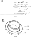
FIG. 1 is a perspective view of a battery provided by some embodiments of the present application. -
FIG. 2 is a structural view of a pole of a battery provided by some embodiments of the present application. -
FIG. 3 is an exploded view ofFIG. 2 . -
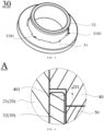
FIG. 4 is a first structural view of a sealing component inFIG. 2 . -
FIG. 5 is a second structural view of the sealing component inFIG. 2 . -
FIG. 6 is an enlarged view of circle A inFIG. 2 . -
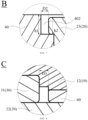
FIG. 7 is an enlarged view of circle B inFIG. 2 . -
FIG. 8 is an enlarged view of circle C inFIG. 2 . - Explanation of reference symbols:
- 100, battery; 10, housing; 11, lateral wall; 12, end plate; 101, first through hole; 102, third accommodation groove; 20, pole; 21, pole connecting part; 22, pole limiting part; 23, pole riveting part;
- 30, sealing component; 31, first sealing part; 32, second sealing part; 3101, recess; 40, riveting component; 401, first accommodation groove; 402, second accommodation groove; 50, outer insulation component; 501, third through hole; 60, inner insulation component; 601, second through hole; 70, adapting piece; D1, first reserved gap; D2, second reserved gap; D3, third reserved gap.
- In the description of the present disclosure, unless otherwise explicitly stipulated and limited, the terms "connected", "connecting", and "fixed" should be understood in a broad sense. For example, it may be a fixed connection, a detachable connection, or an integral body; it may be a mechanical connection or an electrical connection; it may be a direct connection or an indirect connection through an intermediary; it may be an internal connection between two elements or an interaction between two elements. For those of ordinary skill in the art, the specific meanings of the above terms in the present disclosure may be understood based on specific circumstances.
- In the present disclosure, unless otherwise expressly stated and limited, that a first feature is "above" or "below" a second feature may include direct contact between the first and second features, or may also include that the first and second features are not in direct contact but through additional characteristic contact between them. Furthermore, that the first feature is "on", "above", or "over" the second feature may include that the first feature is directly above and diagonally above the second feature, and the first feature has a horizontal height higher than that of the second feature. That the first feature is "under" or "below" the second feature may include that the first feature is directly below and diagonally below the second feature, and the first feature has a horizontal height lower than that of the second feature.
- In the description of the embodiments, orientations or positional relationships indicated by the terms "upper", "lower", "left", "right", "front", "rear" etc. are based on the orientations or positional relationships illustrated in the drawings, the terms are intended to facilitate description and simplify operation, and are not intended to indicate or imply that the device or element referred to must have a specific orientation, be constructed and operate in a specific orientation, and therefore cannot be construed as a limitation of the present disclosure. In addition, the terms "first" and "second" are used to differentiate in description and have no special meaning.
- As illustrated in
FIG. 1, FIG. 2 , andFIG. 3 , the embodiments provide abattery 100. Thebattery 100 includes ahousing 10, apole 20, and asealing component 30. - The
housing 10 includes alateral wall 11 and anend plate 12 connected to thelateral wall 11. Thelateral wall 11 and theend plate 12 are connected to form ahollow housing 10. Thehollow housing 10 is configured to accommodate a battery cell, and a tab at an end of the battery cell is connected to an adapting piece. Theend plate 12 is provided with a first throughhole 101. The first throughhole 101 allows thepole 20 to pass from the inside to the outside of thehousing 10, so that one end of thepole 20 is connected to theadapting piece 70, and the other end of thepole 20 is located outside thehousing 10. Thehousing 10 may be made of aluminum material. Thehousing 10 made of aluminum material has high specific strength, specific modulus, fracture toughness, fatigue strength, and corrosion resistance stability, and has the advantages of light weight and stable molding. - The
lateral wall 11 illustrated inFIG. 1 is cylindrical, and the cylindricallateral wall 11 and theend plate 12 are connected to form acylindrical housing 10. Thelateral wall 11 may also be in the shape of a quadrangular prism, and the quadrangular prismlateral wall 11 and theend plate 12 are connected to form asquare housing 10. - The
pole 20 includes apole connecting part 21 and apole limiting part 22. Thepole connecting part 21 passes through the first throughhole 101, and thepole limiting part 22 is provided on a first end of thepole connecting part 21. Thepole limiting part 22 is located in thehousing 10. Thepole limiting part 22 is located on a side of theend plate 12 close to thelateral wall 11. - A diameter of the
pole connecting part 21 ranges from 3.0 mm to 6.5 mm. The diameter of thepole connecting part 21 may be specifically 3.0 mm, 3.5 mm, 4.0 mm, 4.5 mm, 5.0 mm, 5.5 mm, 6.0 mm, or 6.5 mm. - The
sealing component 30 includes afirst sealing part 31 and asecond sealing part 32. The first sealingpart 31 is provided around thepole connecting part 21, and the first sealingpart 31 is located between thepole limiting part 22 and theend plate 12. A first end of thesecond sealing part 32 is connected to the first sealingpart 31, and the second sealingpart 32 is arranged around thepole connecting part 21. The second sealingpart 32 passes through the first throughhole 101 so that the second sealingpart 32 can seal a part of thepole connecting part 21 provided outside thehousing 10. The second sealingpart 32 is interference-fitted with an inner sidewall of the first throughhole 101. At a position close to a connection between the first sealingpart 31 and thesecond sealing part 32, the first sealingpart 31 is provided with at least onerecess 3101 on a side surface away from the first end of thepole connecting part 21. - The
recess 3101 is configured to provide a deformation space when the first sealingpart 31 is squeezed. That is to say, an arrangement of therecess 3101 provides an accommodation space for deformation at the connection between the first sealingpart 31 and the second sealingpart 32. Therefore, when thepole 20 expands to squeeze thesealing component 30, the sealingcomponent 30 is first deformed at therecess 3101 to relieve thesealing component 30 from directly squeezing other components of thebattery 100 being in contact with the sealingcomponent 30 due to the expansion force of thepole 20. For example, directly squeezing a hole wall of the first throughhole 101 is relieved, thereby reducing the deformation of theend plate 12 and reducing the impact on the overall sealing of thehousing 10, and reducing the impact on the stability of thebattery 100. - As illustrated in
FIG. 4 , therecess 3101 is arranged around an outer periphery of the second sealingpart 32. That is, therecess 3101 and the second sealingpart 32 are co-centrically arranged, so that therecess 3101 arranged along the outer periphery of the second sealingpart 32 accommodates deformation occurring at the connection between the sealingpart 31 and the second sealingpart 32. - As illustrated in
FIG. 5 , a plurality ofrecesses 3101 are arranged at intervals along a circumferential direction of the second sealingpart 32. A shape of therecesses 3101 may be one of cylindrical, prismatic, and hemispherical. Therecesses 3101 may be arranged in a regular shape, or may have an irregular shape, so that the plurality ofrecesses 3101 along the outer periphery of the second sealingpart 32 accommodate deformation occurring at the connection between the first sealingpart 31 and the second sealingpart 32. - The sealing
component 30 may be made of fluororubber material. The sealingcomponent 30 made of fluororubber material has good chemical resistance, making the sealingcomponent 30 particularly suitable for sealing of the battery. - As illustrated in
FIG. 1 to FIG. 3 , thepole 20 further includes a poleriveting part 23. The poleriveting part 23 is provided on a second end of thepole connecting part 21, and the poleriveting part 23 is located on a side of theend plate 12 away from thelateral wall 11. - Based on an arrangement of the pole
riveting part 23, thepole 20 of thebattery 100 can be connected to thehousing 10 of thebattery 100 by riveting to ensure a connection strength between thepole 20 and thehousing 10. - There is a first difference between a radius of the pole
riveting part 23 and a radius of thepole connecting part 21. The first difference ranges from 0.3 mm to 0.8 mm. The first difference may be specifically 0.3 mm, 0.35 mm, 0.4 mm, 0.45 mm, 0.5 mm, 0.55 mm, 0.6 mm, 0.65 mm, 0.7 mm, 0.75 mm, or 0.8 mm. A value of the first difference is controlled from 0.3 mm to 0.8 mm to reduce the risk of cracking due to expansion of the poleriveting part 23. - As illustrated in
FIG. 1 to IG. 3, thebattery 100 further includes ariveting component 40. Theriveting component 40 is at least partially located between the poleriveting part 23 and theend plate 12. A surface of theriveting component 40 close to theend plate 12 is provided with afirst accommodation groove 401. The first end of the second sealingpart 32 of the sealingcomponent 30 is connected to the first sealingpart 31, and the second end of the second sealingpart 32 is accommodated in thefirst accommodation groove 401. Thesecond sealing part 32 is embedded and matched with thefirst accommodation groove 401 to achieve sealing between thepole 20 and thehousing 10 to prevent electrolyte leakage. - As illustrated in
FIG. 6 , there is a first reserved gap D 1 between the second end of the second sealingpart 32 and a bottom wall of thefirst accommodation groove 401. Based on an arrangement of the first reserved gap D1, theriveting component 40 provides an accommodation space for deformation of the second sealingpart 32. On a condition that any one or a combination of two of thepole connecting part 21 and the poleriveting part 23 of thepole 20 expands and squeezes the second sealingpart 32 of the sealingcomponent 30, the second sealingpart 32 deforms to fill the accommodation space formed by theriveting component 40 based on the first reserved gap D1, thereby relieving the second sealingpart 32 from directly squeezing theriveting component 40 due to any one or a combination of two of the expansion force of thepole connecting part 21 and the expansion force of the poleriveting part 23 of thepole 20, reducing the risk of deformation and cracking of theriveting component 40, and improving the stability of thebattery 100. - The first reserved gap D1 ranges from 0.1 mm to 0.4 mm. For example, the first reserved gap D1 may specifically be 0.1 mm, 0.15 mm, 0.2 mm, 0.25 mm, 0.3 mm, 0.35 mm, or 0.4 mm. A value of the first reserved gap D1 is controlled from 0.1 mm to 0.4 mm to ensure that when the
pole connecting part 21 expands and squeezes the second sealingpart 32, the accommodation space formed by theriveting component 40 based on the arrangement of the first reserved gap D1 can accommodate the deformation of the second sealingpart 32, so as to release the deformation force generated by the extrusion of the second sealingpart 32 and reduce an amount of deformation of theriveting component 40 caused by the deformation force of the second sealingpart 32, thereby reducing the risk of cracking due to deformation of theriveting component 40 and improving the stability of thebattery 100. - As illustrated in
FIG. 1 to FIG. 3 , a surface of theriveting component 40 away from theend plate 12 is provided with asecond accommodation groove 402, and the poleriveting part 23 of thepole 20 is accommodated in thesecond accommodation groove 402 to realize the connection between the poleriveting part 23 and theriveting component 40. A depth h1 of thesecond accommodation groove 402 is greater than a thickness h2 of the poleriveting part 23, preventing the poleriveting part 23 from protruding from thesecond accommodation groove 402 to the surface of theriveting component 40 away from theend plate 12, and facilitating a connecting component to weld a plurality ofbatteries 100 so that the plurality ofbatteries 100 are connected in series, or in parallel, or in series and in parallel to form a battery module. A width of thesecond accommodation groove 402 ranges from 3.4 mm to 7.0 mm, so as to realize a riveting fixation between theriveting component 40 and thepole 20. The width of thesecond accommodation groove 402 should be greater than a diameter of thepole connecting part 21. The depth h1 of thesecond accommodation groove 402 ranges from 0.5 mm to 1.2 mm to form an escape space for the expansion of thepole 20 in a thickness direction of the poleriveting part 23. - As illustrated in
FIG. 7 , there is a second reserved gap D2 between a side wall of thesecond accommodation groove 402 and an outer edge of the poleriveting part 23. Based on an arrangement of the second reserved gap D, theriveting component 40 provides an accommodation space for the poleriveting part 23 to expand. The poleriveting part 23 expands to fill the accommodation space formed by theriveting component 40 based on the second reserved gap D2, relieving the poleriveting part 23 from directly squeeze theriveting component 40 due to expansion force generated by the expansion of the poleriveting part 23, reducing the risk of cracking due to deformation of theriveting component 40, and improving the stability of thebattery 100. - The second reserved gap D2 ranges from 0.25 mm to 0.6 mm. For example, the second reserved gap D2 may be specifically 0.25 mm, 0.3 mm, 0.35 mm, 0.4 mm, 0.45 mm, 0.5 mm, 0.55 mm, or 0.6 mm. A value of the second reserved gap D2 is controlled from 0.25 mm to 0.6 mm to ensure that when the pole
riveting part 23 expands to compress theriveting component 40, the accommodation space formed by theriveting component 40 based on the arrangement of the second reserved gap D2 can accommodate the expansion and deformation of the poleriveting part 23, so as to release the deformation force generated by the expansion of the poleriveting part 23, and reduce an amount of deformation of theriveting component 40 due to the deformation force of the poleriveting part 23, thereby reducing the risk of cracking due to the deformation of theriveting component 40 and increasing the stability of thebattery 100. - As illustrated in
FIG. 1 to FIG. 3 , thebattery 100 further includes anouter insulation component 50. Theouter insulation component 50 is disposed around the second sealingpart 32 and at least partially located between theriveting component 40 and theend plate 12. Theouter insulation component 50 is provided with a third throughhole 501. The third throughhole 501 and the first throughhole 101 are co-centrically arranged. Thesecond sealing part 32 penetrates the third throughhole 501, and a hole wall of the third throughhole 501 is in contact with an outer periphery of the second sealingpart 32. Theouter insulation component 50 is configured to insulate theriveting component 40 and theend plate 12 to ensure an insulation connection between thepole 20 and thehousing 10. - As illustrated in
FIG. 1 to FIG. 3 , athird accommodation groove 102 is provided on a surface of theend plate 12 close to theouter insulation component 50. Thethird accommodation groove 102 is provided around the outer periphery of the second sealingpart 32. Part of theouter insulation component 50 is accommodated in thethird accommodation groove 102. Thethird accommodation groove 102 and the first throughhole 101 are co-centrically arranged. Theouter insulation component 50 is embedded and matched with thethird accommodation groove 102 to realize the clamping and fixing of theouter insulation component 50 and theend plate 12 and ensure the insulation connection between the poleriveting part 23 and theend plate 12, thereby realizing thepole 20 insulated from thehousing 10. - As illustrated in
FIG. 1 to FIG. 3 , thebattery 100 further includes aninner insulation component 60. Theinner insulation component 60 is at least partially located between thepole limiting part 22 and theend plate 12. Theinner insulation component 60 is configured to insulate theend plate 12 and the adaptingpiece 70. Theinner insulation component 60 is provided with a second throughhole 601. The second throughhole 601 and the first throughhole 101 are co-centrically arranged. Thefirst sealing part 31 at least partially passes through the second throughhole 601 to ensure the sealing and insulation between thepole 20 and theend plate 12. - As illustrated in
FIG. 8 , there is a third reserved gap D3 between a hole wall of the second throughhole 601 and an outer peripheral of the first sealingpart 31. Thefirst sealing part 31 is provided with an accommodating space for deformation based on an arrangement of the third reserved gap D3. On a condition that any one or a combination of two of thepole connecting part 21 and thepole limiting part 22 of thepole 20 expands to squeeze the first sealingpart 31, the first sealingpart 31 deforms to fill the accommodation space formed based on the third reserved gap D3, thereby relieving the first sealingpart 31 from directly squeeze theinner insulation component 60 due to any one or a combination of two of the expansion force generated by thepole connecting part 21 and the expansion force generated by thepole limiting part 22, thereby reducing the risk of cracking due to deformation of theinner insulation component 60 and improving the stability of thebattery 100. - The third reserved gap D3 ranges from 0.1 mm to 0.4 mm. For example, the first reserved gap D1 may be specifically 0.1 mm, 0.15 mm, 0.2 mm, 0.25 mm, 0.3 mm, 0.35 mm, 0.4 mm. A value of the third reserved gap D3 is controlled from 0.1 mm to 0.4 mm to ensure that when any one or a combination of two of the
pole connecting part 21 and thepole limiting part 22 expands to compress the first sealingpart 31, the accommodation space formed by the first sealingpart 31 based on the arrangement of the third reserved gap D3 can accommodate the deformation of the first sealingpart 31, so as to release the deformation force generated by the first sealingpart 31 due to compressed, and reduce an amount of deformation of theinner insulation component 60 due to the deformation force of the first sealingpart 31, thereby reducing the risk of cracking due to the deformation of theinner insulation component 60 and increasing the stability of thebattery 100. - The embodiments of the present disclosure are introduced in detail above. Specific examples are used in this paper to illustrate the principles and implementation methods of the present disclosure. The description of the above embodiments is only used to help understand the method of the present disclosure and core ideas of the present disclosure. At the same time, for those skilled in the art, there will be changes in the specific implementation mode and application scope based on the ideas of the present disclosure. In summary, the content of this description should not be understood as a limitation of the present disclosure.
Claims (13)
- A battery (100), characterized by comprising:a housing (10), comprising a lateral wall (11) and an end plate (12) connected to the lateral wall (11), wherein the end plate is provided with a first through hole (101);a pole (20), comprising a pole connecting part (21) and a pole limiting part (23), wherein the pole connecting part (21) passes through the first through hole (101), the pole limiting part (23) is provided on a first end of the pole connecting part (21), and the pole limiting part (23) is located on a side of the end plate (12) close to the lateral wall (11); anda sealing component (30), comprising a first sealing part (31) and a second sealing part (32), wherein the first sealing part (31) is arranged around the pole connecting part (21) and located between the pole limiting part (23) and the end plate (12), and a first end of the second sealing part (32) is connected to the first sealing part (31); the second sealing part (32) is arranged around the pole connecting part (21), and the second sealing part (32) is interference-fitted with an inner sidewall of the first through hole (101); and at a position close to a connection between the first sealing part (31) and the second sealing part (32), the first sealing part (31) is provided with at least one recess (3101) on a side surface away from the first end of the pole connecting part (21), and the recess (3101) is configured to provide a deformation space when the first sealing part (31) is squeezed.
- The battery (100) according to claim 1, characterized in that the recess (3101) is arranged around an outer periphery of the second sealing part (32).
- The battery (100) according to claim 1 or claim 2, characterized in that a plurality of recesses (3101) are arranged at intervals along a circumferential direction of the second sealing part (32).
- The battery (100) according to any one of claim 1 to claim 3, characterized in that the pole (20) further comprises a pole riveting part (23) provided on a second end of the pole connecting part (21), and the pole riveting part (23) is located on a side of the end plate (12) away from the lateral wall (11).
- The battery (100) according to claim 4, characterized in that there is a first difference between a radius of the pole riveting part (23) and a radius of the pole connecting part (21), and the first difference ranges from 0.3 mm to 0.8 mm.
- The battery (100) according to claim 4 or claim 5, characterized in that the battery (100) further comprises a riveting component (40), the riveting component (40) is at least partially located between the pole riveting part (23) and the end plate (12), a surface of the riveting component (40) close to the end plate (12) is provided with a first accommodation groove (401), and a second end of the second sealing part (32) is accommodated in the first accommodation groove (401).
- The battery (100) according to claim 6, characterized in that there is a first reserved gap (D1) between the second end of the second sealing part (32) and a bottom wall of the first accommodation groove (401), and the first reserved gap (D1) ranges from 0.1 mm to 0.4 mm.
- The battery (100) according to claim 6 or claim 7, characterized in that a surface of the riveting component (40) away from the end plate (12) is provided with a second accommodation groove (402), and the pole riveting part (23) is accommodated in the second accommodation groove (402).
- The battery (100) according to claim 8, characterized in that there is a second reserved gap (D2) between a side wall of the second accommodation groove (402) and an outer edge of the pole riveting part (23), and the second reserved gap (D2) ranges from 0.25 mm to 0.6 mm.
- The battery (100) according to any one of claim 6 to claim 9, characterized in that the battery (100) further comprises an outer insulation component (50), the outer insulation component (50) is disposed around the second sealing part (32), and the outer insulation component (50) is at least partially located between the riveting component (40) and the end plate (12).
- The battery (100) according to claim 10, characterized in that a surface of the end plate (12) close to the outer insulation component (50) is provided with a third accommodation groove (102), the third accommodation groove is provided around an outer periphery of the second sealing part (32), and part of the outer insulation component (50) is accommodated in the third accommodation groove.
- The battery (100) according to any one of claim 1 to claim 11, characterized in that the battery (100) further comprises an inner insulation component (60), the inner insulation component (60) is at least partially located between the pole limiting part (23) and the end plate (12), the inner insulation component (60) is provided with a second through hole (601), and the first sealing part (31) at least partially passes through the second through hole (601).
- The battery (100) according to claim 12, characterized in that there is a third reserved gap (D3) between a hole wall of the second through hole (601) and an outer periphery of the first sealing part (31), and the third reserved gap (D3) ranges from 0.1 mm to 0.4 mm.
Applications Claiming Priority (2)
| Application Number | Priority Date | Filing Date | Title |
|---|---|---|---|
| CN202322142120.2U CN220627990U (en) | 2023-08-08 | 2023-08-08 | Battery cell |
| PCT/CN2024/106141 WO2025031123A1 (en) | 2023-08-08 | 2024-07-18 | Battery cell |
Publications (1)
| Publication Number | Publication Date |
|---|---|
| EP4539214A1 true EP4539214A1 (en) | 2025-04-16 |
Family
ID=90230117
Family Applications (1)
| Application Number | Title | Priority Date | Filing Date |
|---|---|---|---|
| EP24193709.3A Pending EP4539214A1 (en) | 2023-08-08 | 2024-08-08 | Battery |
Country Status (3)
| Country | Link |
|---|---|
| EP (1) | EP4539214A1 (en) |
| CN (1) | CN220627990U (en) |
| WO (1) | WO2025031123A1 (en) |
Families Citing this family (5)
| Publication number | Priority date | Publication date | Assignee | Title |
|---|---|---|---|---|
| CN220627990U (en) * | 2023-08-08 | 2024-03-19 | 湖北亿纬动力有限公司 | Battery cell |
| CN118380628B (en) * | 2024-06-21 | 2024-11-29 | 蜂巢能源科技股份有限公司 | A single cell and a battery pack |
| CN122122743A (en) * | 2024-09-06 | 2026-05-29 | 宁德时代新能源科技股份有限公司 | Battery cell, battery device and electricity utilization device |
| CN119651002B (en) * | 2025-02-19 | 2025-06-06 | 蜂巢能源科技股份有限公司 | Battery cell cover plate and battery cell |
| CN120184463B (en) * | 2025-05-21 | 2025-09-16 | 欣旺达动力科技股份有限公司 | Single cells, battery packs and electrical equipment |
Citations (2)
| Publication number | Priority date | Publication date | Assignee | Title |
|---|---|---|---|---|
| US20150155532A1 (en) * | 2012-06-25 | 2015-06-04 | Toyota Jidosha Kabushiki Kaisha | Battery |
| US20200350550A1 (en) * | 2019-04-30 | 2020-11-05 | Contemporary Amperex Technology Co., Limited | Cap assembly and secondary battery |
Family Cites Families (6)
| Publication number | Priority date | Publication date | Assignee | Title |
|---|---|---|---|---|
| CN210006769U (en) * | 2019-07-09 | 2020-01-31 | 宁德时代新能源科技股份有限公司 | Top cover assembly and secondary battery |
| CN212571143U (en) * | 2020-08-13 | 2021-02-19 | 珠海冠宇电池股份有限公司 | A battery case and battery |
| CN213212237U (en) * | 2020-09-16 | 2021-05-14 | 比亚迪股份有限公司 | A battery cover plate assembly and battery, a vehicle |
| CN216354485U (en) * | 2021-11-15 | 2022-04-19 | 蜂巢能源科技有限公司 | Sealing ring for battery cover, battery cover with sealing ring and battery module |
| CN217485582U (en) * | 2022-05-31 | 2022-09-23 | 远景动力技术(江苏)有限公司 | Cylindrical battery and electronic equipment |
| CN220627990U (en) * | 2023-08-08 | 2024-03-19 | 湖北亿纬动力有限公司 | Battery cell |
-
2023
- 2023-08-08 CN CN202322142120.2U patent/CN220627990U/en active Active
-
2024
- 2024-07-18 WO PCT/CN2024/106141 patent/WO2025031123A1/en not_active Ceased
- 2024-08-08 EP EP24193709.3A patent/EP4539214A1/en active Pending
Patent Citations (2)
| Publication number | Priority date | Publication date | Assignee | Title |
|---|---|---|---|---|
| US20150155532A1 (en) * | 2012-06-25 | 2015-06-04 | Toyota Jidosha Kabushiki Kaisha | Battery |
| US20200350550A1 (en) * | 2019-04-30 | 2020-11-05 | Contemporary Amperex Technology Co., Limited | Cap assembly and secondary battery |
Also Published As
| Publication number | Publication date |
|---|---|
| WO2025031123A1 (en) | 2025-02-13 |
| CN220627990U (en) | 2024-03-19 |
Similar Documents
| Publication | Publication Date | Title |
|---|---|---|
| KR101240717B1 (en) | Secondary battery | |
| KR101166025B1 (en) | Battery module | |
| US7090944B2 (en) | Alkaline dry cell | |
| JP5712045B2 (en) | Secondary battery | |
| US8481201B2 (en) | Case for secondary battery and lithium secondary battery using the same | |
| US12015162B2 (en) | Cover plate assembly, battery, electricity-consuming apparatus and method for sealing through hole | |
| CN220627990U (en) | Battery cell | |
| US20250158253A1 (en) | Power battery cover and power battery | |
| US20240047795A1 (en) | Battery cover plate assembly, battery and manufacturing method of battery cover plate assembly | |
| CN108369999A (en) | The manufacturing method of charge storage element and charge storage element | |
| EP3062367A1 (en) | Recharcheable battery | |
| EP4693637A1 (en) | Cover plate assembly of battery and secondary battery comprising same | |
| EP4386950A1 (en) | Battery pack | |
| US12347617B2 (en) | Electrochemical energy storage device | |
| US20250055095A1 (en) | Battery | |
| US8445131B2 (en) | Holder case for secondary battery and lithium secondary battery using the same | |
| CN222380700U (en) | Secondary battery, battery pack, and electronic device | |
| CN218123575U (en) | Battery cover plate assembly and battery | |
| CN219717048U (en) | Cover plate assembly and battery | |
| CN215644688U (en) | Battery cover plate assembly and battery | |
| CN217955984U (en) | Button type lithium ion battery shell | |
| CN217468731U (en) | Battery cover plate assembly and battery | |
| CN222620071U (en) | Battery | |
| CN222530600U (en) | Battery Cell | |
| CN217848261U (en) | Battery cover plate assembly and battery |
Legal Events
| Date | Code | Title | Description |
|---|---|---|---|
| PUAI | Public reference made under article 153(3) epc to a published international application that has entered the european phase |
Free format text: ORIGINAL CODE: 0009012 |
|
| STAA | Information on the status of an ep patent application or granted ep patent |
Free format text: STATUS: REQUEST FOR EXAMINATION WAS MADE |
|
| 17P | Request for examination filed |
Effective date: 20240808 |
|
| AK | Designated contracting states |
Kind code of ref document: A1 Designated state(s): AL AT BE BG CH CY CZ DE DK EE ES FI FR GB GR HR HU IE IS IT LI LT LU LV MC ME MK MT NL NO PL PT RO RS SE SI SK SM TR |