EP4539197A1 - Cylindrical battery, and battery pack and vehicle including same - Google Patents
Cylindrical battery, and battery pack and vehicle including same Download PDFInfo
- Publication number
- EP4539197A1 EP4539197A1 EP23939889.4A EP23939889A EP4539197A1 EP 4539197 A1 EP4539197 A1 EP 4539197A1 EP 23939889 A EP23939889 A EP 23939889A EP 4539197 A1 EP4539197 A1 EP 4539197A1
- Authority
- EP
- European Patent Office
- Prior art keywords
- cylindrical battery
- electrode assembly
- electrode
- resist member
- battery
- Prior art date
- Legal status (The legal status is an assumption and is not a legal conclusion. Google has not performed a legal analysis and makes no representation as to the accuracy of the status listed.)
- Pending
Links
Images







Classifications
-
- H—ELECTRICITY
- H01—ELECTRIC ELEMENTS
- H01M—PROCESSES OR MEANS, e.g. BATTERIES, FOR THE DIRECT CONVERSION OF CHEMICAL ENERGY INTO ELECTRICAL ENERGY
- H01M10/00—Secondary cells; Manufacture thereof
- H01M10/42—Methods or arrangements for servicing or maintenance of secondary cells or secondary half-cells
- H01M10/4207—Methods or arrangements for servicing or maintenance of secondary cells or secondary half-cells for several batteries or cells simultaneously or sequentially
-
- H—ELECTRICITY
- H01—ELECTRIC ELEMENTS
- H01M—PROCESSES OR MEANS, e.g. BATTERIES, FOR THE DIRECT CONVERSION OF CHEMICAL ENERGY INTO ELECTRICAL ENERGY
- H01M50/00—Constructional details or processes of manufacture of the non-active parts of electrochemical cells other than fuel cells, e.g. hybrid cells
- H01M50/20—Mountings; Secondary casings or frames; Racks, modules or packs; Suspension devices; Shock absorbers; Transport or carrying devices; Holders
- H01M50/204—Racks, modules or packs for multiple batteries or multiple cells
- H01M50/207—Racks, modules or packs for multiple batteries or multiple cells characterised by their shape
- H01M50/213—Racks, modules or packs for multiple batteries or multiple cells characterised by their shape adapted for cells having curved cross-section, e.g. round or elliptic
-
- H—ELECTRICITY
- H01—ELECTRIC ELEMENTS
- H01M—PROCESSES OR MEANS, e.g. BATTERIES, FOR THE DIRECT CONVERSION OF CHEMICAL ENERGY INTO ELECTRICAL ENERGY
- H01M10/00—Secondary cells; Manufacture thereof
- H01M10/04—Construction or manufacture in general
- H01M10/0431—Cells with wound or folded electrodes
-
- H—ELECTRICITY
- H01—ELECTRIC ELEMENTS
- H01M—PROCESSES OR MEANS, e.g. BATTERIES, FOR THE DIRECT CONVERSION OF CHEMICAL ENERGY INTO ELECTRICAL ENERGY
- H01M50/00—Constructional details or processes of manufacture of the non-active parts of electrochemical cells other than fuel cells, e.g. hybrid cells
- H01M50/10—Primary casings; Jackets or wrappings
- H01M50/147—Lids or covers
- H01M50/148—Lids or covers characterised by their shape
- H01M50/152—Lids or covers characterised by their shape for cells having curved cross-section, e.g. round or elliptic
-
- H—ELECTRICITY
- H01—ELECTRIC ELEMENTS
- H01M—PROCESSES OR MEANS, e.g. BATTERIES, FOR THE DIRECT CONVERSION OF CHEMICAL ENERGY INTO ELECTRICAL ENERGY
- H01M50/00—Constructional details or processes of manufacture of the non-active parts of electrochemical cells other than fuel cells, e.g. hybrid cells
- H01M50/10—Primary casings; Jackets or wrappings
- H01M50/147—Lids or covers
- H01M50/166—Lids or covers characterised by the methods of assembling casings with lids
-
- H—ELECTRICITY
- H01—ELECTRIC ELEMENTS
- H01M—PROCESSES OR MEANS, e.g. BATTERIES, FOR THE DIRECT CONVERSION OF CHEMICAL ENERGY INTO ELECTRICAL ENERGY
- H01M50/00—Constructional details or processes of manufacture of the non-active parts of electrochemical cells other than fuel cells, e.g. hybrid cells
- H01M50/10—Primary casings; Jackets or wrappings
- H01M50/183—Sealing members
- H01M50/184—Sealing members characterised by their shape or structure
-
- H—ELECTRICITY
- H01—ELECTRIC ELEMENTS
- H01M—PROCESSES OR MEANS, e.g. BATTERIES, FOR THE DIRECT CONVERSION OF CHEMICAL ENERGY INTO ELECTRICAL ENERGY
- H01M50/00—Constructional details or processes of manufacture of the non-active parts of electrochemical cells other than fuel cells, e.g. hybrid cells
- H01M50/20—Mountings; Secondary casings or frames; Racks, modules or packs; Suspension devices; Shock absorbers; Transport or carrying devices; Holders
- H01M50/249—Mountings; Secondary casings or frames; Racks, modules or packs; Suspension devices; Shock absorbers; Transport or carrying devices; Holders specially adapted for aircraft or vehicles, e.g. cars or trains
-
- H—ELECTRICITY
- H01—ELECTRIC ELEMENTS
- H01M—PROCESSES OR MEANS, e.g. BATTERIES, FOR THE DIRECT CONVERSION OF CHEMICAL ENERGY INTO ELECTRICAL ENERGY
- H01M50/00—Constructional details or processes of manufacture of the non-active parts of electrochemical cells other than fuel cells, e.g. hybrid cells
- H01M50/50—Current conducting connections for cells or batteries
- H01M50/531—Electrode connections inside a battery casing
- H01M50/538—Connection of several leads or tabs of wound or folded electrode stacks
-
- H—ELECTRICITY
- H01—ELECTRIC ELEMENTS
- H01M—PROCESSES OR MEANS, e.g. BATTERIES, FOR THE DIRECT CONVERSION OF CHEMICAL ENERGY INTO ELECTRICAL ENERGY
- H01M50/00—Constructional details or processes of manufacture of the non-active parts of electrochemical cells other than fuel cells, e.g. hybrid cells
- H01M50/50—Current conducting connections for cells or batteries
- H01M50/572—Means for preventing undesired use or discharge
- H01M50/584—Means for preventing undesired use or discharge for preventing incorrect connections inside or outside the batteries
- H01M50/59—Means for preventing undesired use or discharge for preventing incorrect connections inside or outside the batteries characterised by the protection means
- H01M50/593—Spacers; Insulating plates
-
- H—ELECTRICITY
- H01—ELECTRIC ELEMENTS
- H01M—PROCESSES OR MEANS, e.g. BATTERIES, FOR THE DIRECT CONVERSION OF CHEMICAL ENERGY INTO ELECTRICAL ENERGY
- H01M2220/00—Batteries for particular applications
- H01M2220/20—Batteries in motive systems, e.g. vehicle, ship, plane
-
- Y—GENERAL TAGGING OF NEW TECHNOLOGICAL DEVELOPMENTS; GENERAL TAGGING OF CROSS-SECTIONAL TECHNOLOGIES SPANNING OVER SEVERAL SECTIONS OF THE IPC; TECHNICAL SUBJECTS COVERED BY FORMER USPC CROSS-REFERENCE ART COLLECTIONS [XRACs] AND DIGESTS
- Y02—TECHNOLOGIES OR APPLICATIONS FOR MITIGATION OR ADAPTATION AGAINST CLIMATE CHANGE
- Y02E—REDUCTION OF GREENHOUSE GAS [GHG] EMISSIONS, RELATED TO ENERGY GENERATION, TRANSMISSION OR DISTRIBUTION
- Y02E60/00—Enabling technologies; Technologies with a potential or indirect contribution to GHG emissions mitigation
- Y02E60/10—Energy storage using batteries
-
- Y—GENERAL TAGGING OF NEW TECHNOLOGICAL DEVELOPMENTS; GENERAL TAGGING OF CROSS-SECTIONAL TECHNOLOGIES SPANNING OVER SEVERAL SECTIONS OF THE IPC; TECHNICAL SUBJECTS COVERED BY FORMER USPC CROSS-REFERENCE ART COLLECTIONS [XRACs] AND DIGESTS
- Y02—TECHNOLOGIES OR APPLICATIONS FOR MITIGATION OR ADAPTATION AGAINST CLIMATE CHANGE
- Y02P—CLIMATE CHANGE MITIGATION TECHNOLOGIES IN THE PRODUCTION OR PROCESSING OF GOODS
- Y02P70/00—Climate change mitigation technologies in the production process for final industrial or consumer products
- Y02P70/50—Manufacturing or production processes characterised by the final manufactured product
Definitions
- the present disclosure relates to a cylindrical battery, and a battery pack and a vehicle including the same, and more specifically, it relates to a cylindrical battery configured to reduce deformation of an electrode assembly and the intensity of flame when a thermal event occurs therein, and a battery pack and a vehicle including the same.
- the present disclosure is intended to reduce the intensity of flame and gas when a thermal event occurs.
- a cylindrical battery including: an electrode assembly including a first electrode, a second electrode, and a separator interposed therebetween and having a center hole formed by winding a laminate including the first electrode, the second electrode, and the separator around a winding axis; a battery housing configured to accommodate the electrode assembly through an opening formed on one side thereof; and a resist member at least partially received inside the center hole.
- the resist member may include: a first portion received inside the center hole; and a second portion located outside the center hole.
- the first portion of the resist member may have a shape corresponding to the center hole.
- At least a portion of the second portion of the resist member may be located on the electrode assembly.
- the cylindrical battery may include an insulating member provided between the resist member and the electrode assembly.
- the cylindrical battery may include a first collector including an electrode assembly-coupled portion to be coupled to the electrode assembly and a housing-coupled portion to be coupled to the battery housing.
- the first collector may have a collector hole in a portion corresponding to the center hole.
- At least a portion of the first portion of the resist member may be located inside the collector hole.
- the cylindrical battery may include an insulating member between the resist member and the first collector.
- the resist member may include a porous metal.
- the cylindrical battery may include a top cap configured to cover the opening.
- the second portion of the resist member may have a height corresponding to the distance between the electrode assembly and the top cap.
- a battery unit structure according to the present disclosure may include the cylindrical battery according to the present disclosure.
- FIG. 1 is a diagram illustrating the appearance of a cylindrical battery according to the present disclosure.
- FIG. 2 is a diagram illustrating an electrode assembly before winding, which is included in a cylindrical battery according to the present disclosure.
- FIG. 3 is a partially cross-sectional view of a cylindrical battery according to the present disclosure.
- the battery housing 200 may accommodate the electrode assembly 100 through an opening formed on one side (in the -Z-axis direction).
- the battery housing 200 is a substantially cylindrical container with an opening formed on one side thereof, and may be made of a conductive metal material.
- the battery housing 200 may also accommodate an electrolyte through the opening.
- the battery housing 200 in the present disclosure is not limited to the above form.
- the resist member 300 may be at least partially received inside the center hole H1. At least a portion of the resist member 300 may be inserted into the center hole H1.
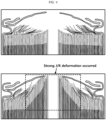
- FIG. 4 is a diagram illustrating the deformation of an electrode assembly when a thermal event occurs inside an existing cylindrical battery.
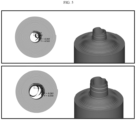
- FIG. 5 is a 3D diagram illustrating the deformation of an electrode assembly when a thermal event occurs inside an existing cylindrical battery.
- FIG. 6 is a diagram illustrating the internal pressure over time when a thermal event occurs inside an existing cylindrical battery.
- FIG. 7 is an enlarged view of a portion in FIG. 6 illustrating the flow of pressure.
- the deformation of the portion adjacent to the center hole of the electrode assembly described above may occur due to drag force (the force acting along the core when the thermal event occurs) generated on the inner circumferential surface of the center hole.
- lift force the force acting on the entire J/R when the thermal event occurs
- lifts the electrode assembly overall may also be one of the causes of the deformation of the electrode assembly.
- the cylindrical battery 10 of the present disclosure may prevent the deformation of the electrode assembly 100 due to the drag force generated along the outer circumference of the center hole H1 when a thermal event occurs inside the battery. This is due to the fact that the resist member 300 is inserted and fixed into the center hole H1, thereby preventing the deformation due to the drag force.
- the resist member 300 may include a porous metal.
- the resist member 300 may include a plurality of metal meshes.
- the resist member 300 may reduce the intensity of flame and gas. High-temperature gas and flame discharged from the center hole may come into contact with the porous material while passing through the resist member to dissipate temperature and energy thereof.
- the resist member 300 may absorb the heat.
- the gas may exit through the porous resist member 300. Accordingly, the resist member 300 may lower the temperature of flame and gas while allowing the gas to exit.
- FIG. 8 is a diagram illustrating a resist member included in a cylindrical battery according to the present disclosure.
- the resist member 300 may include a first portion 310 and a second portion 320.
- the first portion 310 may be received inside the center hole H1.
- the first portion 310 may be inserted into the center hole H1.
- the first portion 310 may have a shape corresponding to the center hole H1.
- the first portion 310 may have a substantially cylindrical shape.
- the first portion 310 may have a diameter substantially equal to or smaller than the diameter of the center hole H1.
- the second portion 320 may be positioned outside the center hole H1. At least a portion of the second portion 320 may be placed on the electrode assembly 100. The second portion 320 may be coupled to the electrode assembly 100 and/or a first collector 400, which will be described later.
- the first portion 310 may be formed to extend downwards (in the -Z-axis direction) from substantially the center of the lower surface (the surface directed in the -Z-axis direction) of the second portion 320.
- the first portion 310 and the second portion 320 may be formed integrally with each other.
- the first portion 310 and the second portion 320 may be manufactured separately, and then coupled to each other by welding or bolting.
- the first portion 310 if the first portion 310 is fitted tightly into the center hole H1 or if the diameter or size of the center hole H1 becomes smaller due to swelling during use of the battery, the first portion 310 will be naturally fixed into the center hole H1 more firmly, thereby more effectively preventing deformation of the electrode assembly 100.
- the second portion 320 may be coupled to the electrode assembly 100 and/or the first collector 400 to maximize the effect of reducing the intensity of flame and gas.
- FIG. 9 is a partially cross-sectional view of a resist member having an insulated surface, which is included in a cylindrical battery according to the present disclosure.
- the cylindrical battery 10 may have an insulating member C.
- the insulating member C may be provided between the resist member 300 and the electrode assembly 100.
- the insulating member C may be provided between the resist member 300 and the electrode assembly 100 inside the center hole H1.
- at least a portion of the outer circumferential surface of the first portion 310 may be insulated.
- the surface of a portion of the resist member 300 facing the electrode assembly 100 may be insulated without a separate member.
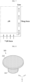
- FIG. 10 is a diagram illustrating a first collector 400 included in a cylindrical battery 10 according to the present disclosure.
- the cylindrical battery 10 may include a first collector 400.
- the first collector 400 may have a collector hole H2 in the portion corresponding to the center hole H1.
- the resist member 300 may be inserted into the center hole H1 through the collector hole H2.
- the first portion 310 may be inserted into the center hole H1 through the collector hole H2. At least a portion of the resist member 300 may be received inside the collector hole H2. At least a portion of the first portion 310 may be received inside the collector hole H2.
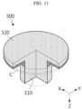
- the cylindrical battery 10 may have an insulating member C between the resist member 300 and the first collector 400.
- the surface of a portion of the resist member 300 facing the first collector 400 may be insulated without a separate member. Accordingly, unnecessary electrical connections or resultant short circuits between the resist member 300 and the first collector 400 may be prevented.
- the second collector P may be electrically coupled to the second electrode 120.
- the second collector P may be electrically coupled to the terminal T.
- the second collector P may have a terminal-coupled portion to be coupled to the terminal T, and a second coupling portion to be coupled to the second electrode 120.
- the top cap 500 may be configured to cover the opening. According to the cylindrical battery 10 according to the present disclosure, since the first electrode 110 and the second electrode 120 are electrically connected through the terminal and the battery housing 200 in the closed portion having the terminal provided thereon, the top cap 500 provided in the opening on the opposite side of the closed portion may be configured to have a polarity or to not have a polarity.
- the top cap 500 may have a venting portion that is configured to be weaker than surrounding areas.
- the venting portion may have a smaller thickness that the surrounding areas.
- the venting portion may be formed by notching one or both sides of the top cap 500, thereby partially reducing the thickness of the top cap 500. According to this structure, if the internal pressure of the battery housing 200 rises to a predetermined level or more due to an abnormality occurring in the battery, the venting portion may be broken so that gas may be discharged.
- the insulator I may be positioned on the second electrode 120 to insulate the battery housing 200 from the tab of the second electrode 120.
- the insulator I may be interposed between the closed portion of the battery housing 200 and the electrode assembly 100 or between the closed portion of the battery housing 200 and the second collector P.
- the insulator I may include, for example, a resin material having insulating properties.
- the insulator I may have a hole substantially at the center such that the terminal T may be electrically connected with the second electrode 120.
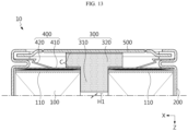
- FIG. 13 is a partially cross-sectional view of a cylindrical battery having a different structure from that in FIG. 3 according to the present disclosure.
- the cylindrical battery 10 may have an insulating member C between the resist member 300 and the top cap 500.
- the surface of a portion of the resist member 300 facing the top cap 500 may be insulated without a separate member. Accordingly, the cylindrical battery 10 may prevent unnecessary electrical connections or resultant short circuits between the resist member 300 and the top cap 500.
- the resist member 300 may be interposed between the electrode assembly 100 and the top cap 500.
- the second portion 320 of the resist member 300 may have a height corresponding to the distance between the electrode assembly 100 and the top cap 500.
- the resist member 300 may effectively prevent the electrode assembly 100 from moving inside the battery housing 200 due to the gap between the top cap 500 and the electrode assembly 100.
- the resist member 300 may prevent damage to the coupling portion between the electrode assembly 100 and the first collector 400 and/or the coupling portion between the first collector 400 and the battery housing 200.
- FIG. 14 is a diagram illustrating a battery unit structure 2 according to the present disclosure.
- the battery unit structure 2 may include a cylindrical battery 10.
- the battery unit structure 2 may be a battery module or battery pack.
- the battery unit structure 2 may further include various elements of the battery pack or battery module, in addition to the cylindrical battery 10, such as a BMS, a bus-bar, a pack (or module) case, a relay, a current sensor, and the like, which are known at the time of filing the present disclosure.
- FIG. 15 is a diagram illustrating a vehicle 1 according to the present disclosure.
- the vehicle 1 according to the present disclosure may include a battery unit structure 2.
- the vehicle 1 may be a hybrid vehicle 1 or an electric vehicle 1.
- the vehicle 1 according to the present disclosure may further include various other components included in the vehicle 1 in addition to the battery unit structure 2.
- the vehicle 1 according to the present disclosure may further include a car body, a motor, and a control device such as an ECU (electronic control unit), in addition to the battery unit structure 2 according to the present disclosure.
- ECU electronic control unit
Landscapes
- Chemical & Material Sciences (AREA)
- Chemical Kinetics & Catalysis (AREA)
- Electrochemistry (AREA)
- General Chemical & Material Sciences (AREA)
- Engineering & Computer Science (AREA)
- Manufacturing & Machinery (AREA)
- Aviation & Aerospace Engineering (AREA)
- Connection Of Batteries Or Terminals (AREA)
- Secondary Cells (AREA)
- Battery Mounting, Suspending (AREA)
- Sealing Battery Cases Or Jackets (AREA)
- Gas Exhaust Devices For Batteries (AREA)
Abstract
Description
- The present disclosure relates to a cylindrical battery, and a battery pack and a vehicle including the same, and more specifically, it relates to a cylindrical battery configured to reduce deformation of an electrode assembly and the intensity of flame when a thermal event occurs therein, and a battery pack and a vehicle including the same.
- The present application claims priority to
Korean Patent Application No. 10-2023-0068708 filed on May 26, 2023 - Secondary batteries, which are easy to apply depending on the product group and have electrical features such as high energy density and the like, are generally used in electric vehicles (EVs) or hybrid electric vehicles (HEVs) that are driven by an electrical drive source, as well as in portable devices.
- These secondary batteries are attracting attention as a new energy source for improving eco-friendliness and energy efficiency because of the primary advantage of dramatically reducing the use of fossil fuels and another advantage of not generating byproducts resulting from energy use.
- Current secondary batteries widely used include lithium-ion batteries, lithium-polymer batteries, nickel-cadmium batteries, nickel-hydrogen batteries, nickel-zinc batteries, and the like. The operating voltage of this unit secondary battery cell, that is, the unit battery cell, is approximately 2.5V to 4.5V. Therefore, when an output voltage higher than this is required, a battery pack may be configured by connecting a plurality of battery cells in series. In addition, a battery pack may be configured by connecting multiple batteries in parallel depending on the charge/discharge capacity required for the battery pack. Accordingly, the number of batteries included in the battery pack and the electrical connection may be configured in various ways depending on the required output voltage or charge/discharge capacity.
- However, in the case where a large number of battery modules are provided densely in a small space, they may be vulnerable to accidents such as fire or explosion. For example, in the case where a flame occurs due to a thermal event inside any one battery cell, the flame may transfer to the outside, causing a chain of thermal events in adjacent battery cells.
- The present disclosure has been designed to solve the problems of the related art, and therefore the present disclosure is intended to prevent deformation of the electrode assembly when a thermal event occurs inside the battery cell.
- In another aspect, the present disclosure is intended to reduce the intensity of flame and gas when a thermal event occurs.
- However, the technical problems that the present disclosure seeks to solve are not limited to the above-mentioned problems, and other problems not mentioned above will be clearly understood by those skilled in the art from the description of the invention described below.
- According to one aspect of the present disclosure, there is provided a cylindrical battery including: an electrode assembly including a first electrode, a second electrode, and a separator interposed therebetween and having a center hole formed by winding a laminate including the first electrode, the second electrode, and the separator around a winding axis; a battery housing configured to accommodate the electrode assembly through an opening formed on one side thereof; and a resist member at least partially received inside the center hole.
- The resist member may include: a first portion received inside the center hole; and a second portion located outside the center hole.
- The first portion of the resist member may have a shape corresponding to the center hole.
- At least a portion of the second portion of the resist member may be located on the electrode assembly.
- The cylindrical battery may include an insulating member provided between the resist member and the electrode assembly.
- The cylindrical battery may include a first collector including an electrode assembly-coupled portion to be coupled to the electrode assembly and a housing-coupled portion to be coupled to the battery housing.
- The first collector may have a collector hole in a portion corresponding to the center hole.
- At least a portion of the first portion of the resist member may be located inside the collector hole.
- The cylindrical battery may include an insulating member between the resist member and the first collector.
- The resist member may include a porous metal.
- The cylindrical battery may include a top cap configured to cover the opening.
- The second portion of the resist member may have a height corresponding to the distance between the electrode assembly and the top cap.
- The cylindrical battery may include an insulating member provided between the resist member and the top cap.
- A battery unit structure according to the present disclosure may include the cylindrical battery according to the present disclosure.
- A vehicle according to the present disclosure may include the battery unit structure according to the present disclosure.
- According to one aspect of the present disclosure, when a thermal event occurs inside the battery, deformation of the electrode assembly due to drag force generated along the outer circumference of the center hole can be prevented. This is due to the fact that the resist member is inserted and fixed into the center hole, thereby preventing deformation due to drag force.
- Additionally, the resist member may include a porous metal. The resist member may include a plurality of metal meshes. In this case, the resist member is able to reduce the intensity of flame and gas. If flame or gas comes into contact with the resist member including a porous metal, the resist member may absorb heat. At the same time, the gas may exit through the porous resist member. Therefore, the resist member may lower the temperature of flame and gas while allowing the gas to exit.
- According to another aspect of the present disclosure, if the resist member is fitted tightly into the center hole or if the diameter or size of the center hole becomes smaller due to swelling during use of the battery, the resist member will be fixed more firmly to the center, thereby more effectively preventing deformation of the electrode assembly. In addition, the resist member may be coupled to the electrode assembly and/or the first collector to maximize the effect of reducing the intensity of flame and gas.
- According to another aspect of the present disclosure, even if the separator ruptures as the diameter or size of the center hole becomes smaller than necessary due to swelling, it is possible to prevent a short circuit between the electrode assembly and the resist member.
- According to another aspect of the present disclosure, it is possible to prevent unnecessary electrical connections or resultant short circuits between the resist member and the first collector.
-
-
FIG. 1 is a diagram illustrating the appearance of a cylindrical battery according to the present disclosure. -
FIG. 2 is a diagram illustrating an electrode assembly before winding, which is included in a cylindrical battery according to the present disclosure. -
FIG. 3 is a partially cross-sectional view of a cylindrical battery according to the present disclosure. -
FIG. 4 is a diagram illustrating the deformation of an electrode assembly when a thermal event occurs inside an existing cylindrical battery. -
FIG. 5 is a 3D diagram illustrating the deformation of an electrode assembly when a thermal event occurs inside an existing cylindrical battery. -
FIG. 6 is a diagram illustrating the internal pressure over time when a thermal event occurs inside an existing cylindrical battery. -
FIG. 7 is an enlarged view of a portion inFIG. 6 illustrating the flow of pressure. -
FIG. 8 is a diagram illustrating a resist member included in a cylindrical battery according to the present disclosure. -
FIG. 9 is a partially cross-sectional view of a resist member having an insulated surface, which is included in a cylindrical battery according to the present disclosure. -
FIG. 10 is a diagram illustrating a first collector included in a cylindrical battery according to the present disclosure. -
FIG. 11 is a partially cross-sectional view of a resist member having an insulated portion different from that of the resist member shown inFIG. 9 , which is included in a cylindrical battery according to the present disclosure. -
FIG. 12 is a cross-sectional view of a cylindrical battery according to the present disclosure. -
FIG. 13 is a partially cross-sectional view of a cylindrical battery having a different structure from that inFIG. 3 according to the present disclosure. -
FIG. 14 is a diagram illustrating a battery unit structure according to the present disclosure. -
FIG. 15 is a diagram illustrating a vehicle according to the present disclosure. - Hereinafter, preferred embodiments of the present disclosure will be described in detail with reference to the accompanying drawings. The accompanying drawings illustrate a preferred embodiment of the present disclosure and, together with the detailed description of the invention, serve to provide further understanding of the technical idea of the present disclosure, and thus, the present disclosure is not construed as being limited to the drawings. The same reference numerals indicate the same elements. In addition, the thicknesses, ratios, and sizes of the elements in the attached drawings may be exaggerated to effectively explain the technical features of the present disclosure.
- It should be understood that the terms or words used in the specification and the appended claims should not be construed as limited to general and dictionary meanings, but interpreted based on the meanings and concepts corresponding to technical aspects of the present disclosure on the basis of the principle that the inventor is allowed to define terms appropriately for the best explanation.
- Meanwhile, although terms indicating directions such as upward, downward, left, right, forward, and backward are used in this specification, it is obvious to those skilled in the art that these terms are only for convenience of explanation and may vary depending on the location of the target object or the location of the observer.
- Therefore, the configurations proposed in the embodiments and drawings of this specification indicate only the most preferable embodiment of the present disclosure and do not represent all technical ideas of the present disclosure, so it should be understood that various equivalents and modifications could be made thereto at the time of filing the application.
-
FIG. 1 is a diagram illustrating the appearance of a cylindrical battery according to the present disclosure.FIG. 2 is a diagram illustrating an electrode assembly before winding, which is included in a cylindrical battery according to the present disclosure.FIG. 3 is a partially cross-sectional view of a cylindrical battery according to the present disclosure. - Referring to
FIGS. 1 to 3 , thecylindrical battery 10 according to the present disclosure may include anelectrode assembly 100, abattery housing 200, and a resistmember 300. - The
electrode assembly 100 may include afirst electrode 110, asecond electrode 120, and aseparator 130 interposed therebetween. Theelectrode assembly 100 may have a center hole H1 that is formed by winding a laminate 100' including thefirst electrode 110, thesecond electrode 120, and theseparator 130 around a winding axis. Thefirst electrode 110, thesecond electrode 120, and theseparator 130 interposed therebetween may be wound around the winding axis, thereby providing the center hole H1. Thefirst electrode 110 may be a negative electrode or positive electrode, and thesecond electrode 120 may be an electrode having a polarity opposite that of thefirst electrode 110. Referring toFIG. 2 , theelectrode assembly 100 may be manufactured by winding the laminate 100' that is formed by sequentially laminating thefirst electrode 110, theseparator 130, thesecond electrode 120, and theseparator 130 at least once. That is, theelectrode assembly 100 applied to the present disclosure may be a jellyroll-type electrode assembly 100. Theelectrode assembly 100 may have a center hole H1 formed at substantially the center thereof and extending in the height direction (parallel to the Z-axis). - The
battery housing 200 may accommodate theelectrode assembly 100 through an opening formed on one side (in the -Z-axis direction). Thebattery housing 200 is a substantially cylindrical container with an opening formed on one side thereof, and may be made of a conductive metal material. Thebattery housing 200 may also accommodate an electrolyte through the opening. However, thebattery housing 200 in the present disclosure is not limited to the above form. - The resist
member 300 may be at least partially received inside the center hole H1. At least a portion of the resistmember 300 may be inserted into the center hole H1. -
FIG. 4 is a diagram illustrating the deformation of an electrode assembly when a thermal event occurs inside an existing cylindrical battery.FIG. 5 is a 3D diagram illustrating the deformation of an electrode assembly when a thermal event occurs inside an existing cylindrical battery.FIG. 6 is a diagram illustrating the internal pressure over time when a thermal event occurs inside an existing cylindrical battery.FIG. 7 is an enlarged view of a portion inFIG. 6 illustrating the flow of pressure. - Hereinafter, problems caused in the case where a thermal event occurs inside the battery in the conventional invention will be described in detail with reference to
FIGS. 4 to 7 . - Referring to
FIGS. 4 and5 , if flame and gas is discharged through a center hole due to a thermal event occurring inside the battery, the electrode assembly is deformed. In particular, a portion adj acent to the center hole of the electrode assembly is greatly deformed. - Referring to
FIGS. 6 and7 , the deformation of the portion adjacent to the center hole of the electrode assembly described above may occur due to drag force (the force acting along the core when the thermal event occurs) generated on the inner circumferential surface of the center hole. In addition, lift force (the force acting on the entire J/R when the thermal event occurs) that lifts the electrode assembly overall may also be one of the causes of the deformation of the electrode assembly. - However, the
cylindrical battery 10 of the present disclosure, to which the resistmember 300 is applied, may prevent the deformation of theelectrode assembly 100 due to the drag force generated along the outer circumference of the center hole H1 when a thermal event occurs inside the battery. This is due to the fact that the resistmember 300 is inserted and fixed into the center hole H1, thereby preventing the deformation due to the drag force. - In addition, the resist
member 300 may include a porous metal. The resistmember 300 may include a plurality of metal meshes. In this case, the resistmember 300 may reduce the intensity of flame and gas. High-temperature gas and flame discharged from the center hole may come into contact with the porous material while passing through the resist member to dissipate temperature and energy thereof. When the flame and gas comes into contact with the resistmember 300 including a porous metal, the resistmember 300 may absorb the heat. At the same time, the gas may exit through the porous resistmember 300. Accordingly, the resistmember 300 may lower the temperature of flame and gas while allowing the gas to exit. -
FIG. 8 is a diagram illustrating a resist member included in a cylindrical battery according to the present disclosure. - Referring to
FIG. 8 , the resistmember 300 may include afirst portion 310 and asecond portion 320. - The
first portion 310 may be received inside the center hole H1. Thefirst portion 310 may be inserted into the center hole H1. Thefirst portion 310 may have a shape corresponding to the center hole H1. Thefirst portion 310 may have a substantially cylindrical shape. Thefirst portion 310 may have a diameter substantially equal to or smaller than the diameter of the center hole H1. - The
second portion 320 may be positioned outside the center hole H1. At least a portion of thesecond portion 320 may be placed on theelectrode assembly 100. Thesecond portion 320 may be coupled to theelectrode assembly 100 and/or afirst collector 400, which will be described later. - The
first portion 310 may be formed to extend downwards (in the -Z-axis direction) from substantially the center of the lower surface (the surface directed in the -Z-axis direction) of thesecond portion 320. Thefirst portion 310 and thesecond portion 320 may be formed integrally with each other. Alternatively, thefirst portion 310 and thesecond portion 320 may be manufactured separately, and then coupled to each other by welding or bolting. - According to this configuration of the present disclosure, if the
first portion 310 is fitted tightly into the center hole H1 or if the diameter or size of the center hole H1 becomes smaller due to swelling during use of the battery, thefirst portion 310 will be naturally fixed into the center hole H1 more firmly, thereby more effectively preventing deformation of theelectrode assembly 100. In addition, thesecond portion 320 may be coupled to theelectrode assembly 100 and/or thefirst collector 400 to maximize the effect of reducing the intensity of flame and gas. -
FIG. 9 is a partially cross-sectional view of a resist member having an insulated surface, which is included in a cylindrical battery according to the present disclosure. - Referring to
FIG. 9 together withFIG. 3 , thecylindrical battery 10 may have an insulating member C. - The insulating member C may be provided between the resist
member 300 and theelectrode assembly 100. For example, as shown inFIG. 9 , the insulating member C may be provided between the resistmember 300 and theelectrode assembly 100 inside the center hole H1. In this case, at least a portion of the outer circumferential surface of thefirst portion 310 may be insulated. However, the surface of a portion of the resistmember 300 facing theelectrode assembly 100 may be insulated without a separate member. - According to this configuration of the present disclosure, even if the
separator 130 ruptures as the diameter or size of the center hole H1 becomes smaller than necessary due to swelling, it is possible to prevent a short circuit between theelectrode assembly 100 and the resistmember 300. -
FIG. 10 is a diagram illustrating afirst collector 400 included in acylindrical battery 10 according to the present disclosure. - Referring to
FIG. 10 together withFIG. 3 , thecylindrical battery 10 may include afirst collector 400. - The
first collector 400 may include an electrode assembly-coupledportion 410 and a housing-coupledportion 420. The electrode assembly-coupledportion 410 may be coupled to thefirst electrode 110. The electrode assembly-coupledportion 410 may be formed to extend outwards from asupport portion 430 disposed on theelectrode assembly 100. The housing-coupledportion 420 may be coupled to thebattery housing 200. The housing-coupledportion 420 may be formed to extend outwards from thesupport portion 430 disposed on theelectrode assembly 100. At least a portion of thesecond portion 320 may be positioned in the area corresponding to thesupport portion 430 disposed on theelectrode assembly 100. - The
first collector 400 may have a collector hole H2 in the portion corresponding to the center hole H1. The resistmember 300 may be inserted into the center hole H1 through the collector hole H2. Thefirst portion 310 may be inserted into the center hole H1 through the collector hole H2. At least a portion of the resistmember 300 may be received inside the collector hole H2. At least a portion of thefirst portion 310 may be received inside the collector hole H2. - The collector hole H2 may function as a passage for insertion of a welding rod for welding between a battery terminal T and a second collector P, which will be described later, or welding between the battery terminal T and the
second electrode 120, or for radiation of laser thereon. In addition, it may also function as a passage to ensure effective impregnation of an electrolyte into theelectrode assembly 100 when injecting the electrolyte into the battery, and thefirst collector 400 may have an injection hole H3 on the electrode assembly-coupledportion 410 in order to improve the impregnation performance more effectively. -
FIG. 11 is a partially cross-sectional view of a resist member included in a cylindrical battery according to the present disclosure, which has an insulated portion different from that of the resist member shown inFIG. 9 . - Referring to
FIG. 11 together withFIG. 3 , thecylindrical battery 10 may have an insulating member C between the resistmember 300 and thefirst collector 400. However, the surface of a portion of the resistmember 300 facing thefirst collector 400 may be insulated without a separate member. Accordingly, unnecessary electrical connections or resultant short circuits between the resistmember 300 and thefirst collector 400 may be prevented. -
FIG. 12 is a cross-sectional view of a cylindrical battery according to the present disclosure. - Referring to
FIG. 12 , thecylindrical battery 10 may include atop cap 500, a terminal T, a second collector P, and an insulator I. - The terminal T may be electrically connected to the
second electrode 120. The terminal T may penetrate through a closed portion of thebattery housing 200, which is provided on the opposite side of the opening of thebattery housing 200, to be electrically connected to thesecond electrode 120. The terminal T may penetrate through substantially the center of the closed portion of thebattery housing 200. The terminal T may be coupled to the second collector P, which will be described later, thereby establishing an electrical connection with theelectrode assembly 100. - The second collector P may be electrically coupled to the
second electrode 120. The second collector P may be electrically coupled to the terminal T. The second collector P may have a terminal-coupled portion to be coupled to the terminal T, and a second coupling portion to be coupled to thesecond electrode 120. - The
top cap 500 may be configured to cover the opening. According to thecylindrical battery 10 according to the present disclosure, since thefirst electrode 110 and thesecond electrode 120 are electrically connected through the terminal and thebattery housing 200 in the closed portion having the terminal provided thereon, thetop cap 500 provided in the opening on the opposite side of the closed portion may be configured to have a polarity or to not have a polarity. - The
top cap 500 may have a venting portion that is configured to be weaker than surrounding areas. The venting portion may have a smaller thickness that the surrounding areas. The venting portion may be formed by notching one or both sides of thetop cap 500, thereby partially reducing the thickness of thetop cap 500. According to this structure, if the internal pressure of thebattery housing 200 rises to a predetermined level or more due to an abnormality occurring in the battery, the venting portion may be broken so that gas may be discharged. - The insulator I may be positioned on the
second electrode 120 to insulate thebattery housing 200 from the tab of thesecond electrode 120. The insulator I may be interposed between the closed portion of thebattery housing 200 and theelectrode assembly 100 or between the closed portion of thebattery housing 200 and the second collector P. The insulator I may include, for example, a resin material having insulating properties. The insulator I may have a hole substantially at the center such that the terminal T may be electrically connected with thesecond electrode 120. -
FIG. 13 is a partially cross-sectional view of a cylindrical battery having a different structure from that inFIG. 3 according to the present disclosure. - Referring to
FIG. 13 , thecylindrical battery 10 may have an insulating member C between the resistmember 300 and thetop cap 500. However, the surface of a portion of the resistmember 300 facing thetop cap 500 may be insulated without a separate member. Accordingly, thecylindrical battery 10 may prevent unnecessary electrical connections or resultant short circuits between the resistmember 300 and thetop cap 500. - Referring to
FIG. 13 together withFIG. 12 , the resistmember 300 may be interposed between theelectrode assembly 100 and thetop cap 500. Thesecond portion 320 of the resistmember 300 may have a height corresponding to the distance between theelectrode assembly 100 and thetop cap 500. - According to this configuration of the present disclosure, the resist
member 300 may effectively prevent theelectrode assembly 100 from moving inside thebattery housing 200 due to the gap between thetop cap 500 and theelectrode assembly 100. In particular, referring toFIGS. 6 and7 , the deformation of theelectrode assembly 100 due to the lift force described above may be prevented. In addition, the resistmember 300 may prevent damage to the coupling portion between theelectrode assembly 100 and thefirst collector 400 and/or the coupling portion between thefirst collector 400 and thebattery housing 200. -
FIG. 14 is a diagram illustrating abattery unit structure 2 according to the present disclosure. - Referring to
FIG. 14 , thebattery unit structure 2 according to the present disclosure may include acylindrical battery 10. For example, thebattery unit structure 2 may be a battery module or battery pack. Thebattery unit structure 2 may further include various elements of the battery pack or battery module, in addition to thecylindrical battery 10, such as a BMS, a bus-bar, a pack (or module) case, a relay, a current sensor, and the like, which are known at the time of filing the present disclosure. -
FIG. 15 is a diagram illustrating avehicle 1 according to the present disclosure. - Referring to
FIG. 15 , thevehicle 1 according to the present disclosure may include abattery unit structure 2. Thevehicle 1 may be ahybrid vehicle 1 or anelectric vehicle 1. Thevehicle 1 according to the present disclosure may further include various other components included in thevehicle 1 in addition to thebattery unit structure 2. For example, thevehicle 1 according to the present disclosure may further include a car body, a motor, and a control device such as an ECU (electronic control unit), in addition to thebattery unit structure 2 according to the present disclosure. - As described above, although the present disclosure has been described based on preferred embodiments with reference to the attached drawings, it is obvious to those skilled in the art that various modifications can be made from this description without departing from the scope of the present disclosure. Accordingly, the scope of the present disclosure should be construed according to the claims encompassing the various modifications.
Claims (15)
- A cylindrical battery comprising:an electrode assembly comprising a first electrode, a second electrode, and a separator interposed therebetween and having a center hole formed by winding a laminate comprising the first electrode, the second electrode, and the separator around a winding axis;a battery housing configured to accommodate the electrode assembly through an opening formed on one side thereof; anda resist member at least partially received inside the center hole.
- The cylindrical battery according to claim 1,
wherein the resist member comprises:a first portion received inside the center hole; anda second portion located outside the center hole. - The cylindrical battery according to claim 2,wherein the first portion of the resist member hasa shape corresponding to the center hole.
- The cylindrical battery according to claim 2,
wherein at least a portion of the second portion of the resist member is located on the electrode assembly. - The cylindrical battery according to claim 4,
further comprising
an insulating member provided between the resist member and the electrode assembly. - The cylindrical battery according to claim 2,
further comprising
a first collector comprising an electrode assembly-coupled portion to be coupled to the electrode assembly and a housing-coupled portion to be coupled to the battery housing. - The cylindrical battery according to claim 6,wherein the first collector hasa collector hole in a portion corresponding to the center hole.
- The cylindrical battery according to claim 7,
wherein at least a portion of the first portion of the resist member is located inside the collector hole. - The cylindrical battery according to claim 6,
further comprising
an insulating member between the resist member and the first collector. - The cylindrical battery according to claim 1,wherein the resist member comprisesa porous metal.
- The cylindrical battery according to claim 2,
further comprising
a top cap configured to cover the opening. - The cylindrical battery according to claim 11,wherein the second portion of the resist memberhas a height corresponding to the distance between the electrode assembly and the top cap.
- The cylindrical battery according to claim 12,
further comprising
an insulating member provided between the resist member and the top cap. - A battery unit structure comprising the cylindrical battery according to any one of claims 1 to 13.
- A vehicle comprising the battery unit structure according to claim 14.
Applications Claiming Priority (2)
| Application Number | Priority Date | Filing Date | Title |
|---|---|---|---|
| KR1020230068708A KR20240170325A (en) | 2023-05-26 | 2023-05-26 | Cylindrical battery cell, and battery pack and vehicle including the same |
| PCT/KR2023/019927 WO2024248250A1 (en) | 2023-05-26 | 2023-12-05 | Cylindrical battery, and battery pack and vehicle including same |
Publications (2)
| Publication Number | Publication Date |
|---|---|
| EP4539197A1 true EP4539197A1 (en) | 2025-04-16 |
| EP4539197A4 EP4539197A4 (en) | 2025-11-12 |
Family
ID=93657712
Family Applications (1)
| Application Number | Title | Priority Date | Filing Date |
|---|---|---|---|
| EP23939889.4A Pending EP4539197A4 (en) | 2023-05-26 | 2023-12-05 | CYLINDRICAL BATTERY AND BATTERY PACK AND VEHICLE WITH IT |
Country Status (6)
| Country | Link |
|---|---|
| EP (1) | EP4539197A4 (en) |
| JP (1) | JP2025523286A (en) |
| KR (1) | KR20240170325A (en) |
| CN (1) | CN119678289A (en) |
| CA (1) | CA3263241A1 (en) |
| WO (1) | WO2024248250A1 (en) |
Family Cites Families (15)
| Publication number | Priority date | Publication date | Assignee | Title |
|---|---|---|---|---|
| KR0153364B1 (en) * | 1995-11-17 | 1998-11-16 | 배순훈 | Lithium Battery with Heat Dissipation Net |
| JP4499680B2 (en) * | 2005-03-30 | 2010-07-07 | 三星エスディアイ株式会社 | Cylindrical lithium ion secondary battery |
| JP2009218013A (en) * | 2008-03-07 | 2009-09-24 | Sanyo Electric Co Ltd | Sealed battery |
| US20110262783A1 (en) * | 2010-04-27 | 2011-10-27 | Tesla Motors, Inc. | Battery Cell with Center Pin Comprised of an Intumescent Material |
| JP6080201B2 (en) * | 2013-02-26 | 2017-02-15 | ホーチキ株式会社 | Fire extinguishing apparatus and aging method using the same |
| KR102048763B1 (en) * | 2015-10-21 | 2019-11-27 | 주식회사 엘지화학 | Secondary battery |
| KR102616467B1 (en) * | 2018-09-27 | 2023-12-21 | 삼성에스디아이 주식회사 | Electrode assembly and secondary battery comprising the same |
| KR102480958B1 (en) * | 2018-10-05 | 2022-12-23 | 주식회사 엘지에너지솔루션 | Rechargeable battery |
| KR102753295B1 (en) * | 2018-12-06 | 2025-01-14 | 주식회사 엘지에너지솔루션 | Rechargeable battery and battery pack comprising the same |
| KR20220019477A (en) * | 2020-08-10 | 2022-02-17 | 삼성에스디아이 주식회사 | Secondary Battery |
| PL4047703T3 (en) * | 2021-01-19 | 2024-04-29 | Lg Energy Solution, Ltd. | Electrode terminal, cylindrical battery cell, battery pack and vehicle |
| WO2022232072A1 (en) * | 2021-04-25 | 2022-11-03 | Microvast, Inc. | Method of preparing electrochemical device and electrochemical device |
| KR20220154972A (en) * | 2021-05-14 | 2022-11-22 | 에스케이온 주식회사 | Battery pack |
| KR102713866B1 (en) | 2021-11-11 | 2024-10-04 | 재단법인 포항금속소재산업진흥원 | Method of separating metal from cathode active material in waste battery using alkaline solution |
| CN116544569A (en) * | 2023-04-12 | 2023-08-04 | 楚能新能源股份有限公司 | Battery, battery pack and electric equipment |
-
2023
- 2023-05-26 KR KR1020230068708A patent/KR20240170325A/en active Pending
- 2023-12-05 CN CN202380052923.9A patent/CN119678289A/en active Pending
- 2023-12-05 WO PCT/KR2023/019927 patent/WO2024248250A1/en not_active Ceased
- 2023-12-05 JP JP2024569400A patent/JP2025523286A/en active Pending
- 2023-12-05 EP EP23939889.4A patent/EP4539197A4/en active Pending
- 2023-12-05 CA CA3263241A patent/CA3263241A1/en active Pending
Also Published As
| Publication number | Publication date |
|---|---|
| CA3263241A1 (en) | 2025-06-09 |
| JP2025523286A (en) | 2025-07-18 |
| EP4539197A4 (en) | 2025-11-12 |
| KR20240170325A (en) | 2024-12-03 |
| WO2024248250A1 (en) | 2024-12-05 |
| CN119678289A (en) | 2025-03-21 |
Similar Documents
| Publication | Publication Date | Title |
|---|---|---|
| EP2226868B1 (en) | Rechargeable battery and module thereof | |
| EP2254176B1 (en) | Rechargeable battery | |
| CN107949932B (en) | Battery cell having venting structure using adhesive tape | |
| US9627677B2 (en) | Rechargeable battery | |
| KR102188429B1 (en) | Jelly-Roll Type Electrode Having Uncoated Part of Electrode Active Material | |
| KR102951291B1 (en) | Battery module having a simple connection structure between cell lead and voltage sensing member and battery pack including the same | |
| WO2009047893A2 (en) | Sealed battery | |
| KR20140065956A (en) | Rechargeable battery | |
| CN108023034A (en) | Battery cell and method for manufacturing a battery cell | |
| EP4604312A1 (en) | Battery cell, battery, and electric device | |
| EP2330660B1 (en) | Rechargeable battery | |
| EP3358644B1 (en) | Battery cell and battery module | |
| CA3263241A1 (en) | Cylindrical battery, and battery pack and vehicle including same | |
| EP4571963A2 (en) | Cylindrical battery, and battery pack and vehicle including same | |
| EP4668451A1 (en) | Battery, and battery pack and vehicle comprising same | |
| KR20260065343A (en) | Battery cell, battery pack and vehicle including the same | |
| EP4664668A1 (en) | Battery cell, battery, and electrical device | |
| US20250015440A1 (en) | Battery cell, battery, and electric apparatus | |
| EP4697465A1 (en) | Battery, and battery pack and vehicle including same | |
| EP4693677A1 (en) | Battery, and battery pack and vehicle including same | |
| KR20260066647A (en) | Battery cell, battery pack and vehicle including the same | |
| KR20260057735A (en) | Battery cell and battery pack and vehicle including the same | |
| KR20260071553A (en) | Battery cell and battery pack and vehicle including the same | |
| KR20260059948A (en) | Current collector, Battery cell and Battery pack including the same | |
| KR20260054364A (en) | Battery cell, battery pack and vehicle including the same |
Legal Events
| Date | Code | Title | Description |
|---|---|---|---|
| STAA | Information on the status of an ep patent application or granted ep patent |
Free format text: STATUS: THE INTERNATIONAL PUBLICATION HAS BEEN MADE |
|
| PUAI | Public reference made under article 153(3) epc to a published international application that has entered the european phase |
Free format text: ORIGINAL CODE: 0009012 |
|
| STAA | Information on the status of an ep patent application or granted ep patent |
Free format text: STATUS: REQUEST FOR EXAMINATION WAS MADE |
|
| 17P | Request for examination filed |
Effective date: 20250107 |
|
| AK | Designated contracting states |
Kind code of ref document: A1 Designated state(s): AL AT BE BG CH CY CZ DE DK EE ES FI FR GB GR HR HU IE IS IT LI LT LU LV MC ME MK MT NL NO PL PT RO RS SE SI SK SM TR |
|
| A4 | Supplementary search report drawn up and despatched |
Effective date: 20251010 |
|
| RIC1 | Information provided on ipc code assigned before grant |
Ipc: H01M 10/42 20060101AFI20251006BHEP Ipc: H01M 10/04 20060101ALI20251006BHEP Ipc: H01M 50/152 20210101ALI20251006BHEP Ipc: H01M 50/538 20210101ALI20251006BHEP Ipc: H01M 50/213 20210101ALI20251006BHEP Ipc: H01M 50/249 20210101ALI20251006BHEP Ipc: H01M 50/184 20210101ALI20251006BHEP Ipc: H01M 50/593 20210101ALI20251006BHEP |