EP4539189A1 - Battery pack for an electric road vehicle and method for the compensation of the thickness variation of an electrochemical cell for said battery pack - Google Patents
Battery pack for an electric road vehicle and method for the compensation of the thickness variation of an electrochemical cell for said battery pack Download PDFInfo
- Publication number
- EP4539189A1 EP4539189A1 EP24205155.5A EP24205155A EP4539189A1 EP 4539189 A1 EP4539189 A1 EP 4539189A1 EP 24205155 A EP24205155 A EP 24205155A EP 4539189 A1 EP4539189 A1 EP 4539189A1
- Authority
- EP
- European Patent Office
- Prior art keywords
- cell
- battery pack
- along
- compensation element
- thickness
- Prior art date
- Legal status (The legal status is an assumption and is not a legal conclusion. Google has not performed a legal analysis and makes no representation as to the accuracy of the status listed.)
- Pending
Links
Images






Classifications
-
- H—ELECTRICITY
- H01—ELECTRIC ELEMENTS
- H01M—PROCESSES OR MEANS, e.g. BATTERIES, FOR THE DIRECT CONVERSION OF CHEMICAL ENERGY INTO ELECTRICAL ENERGY
- H01M10/00—Secondary cells; Manufacture thereof
- H01M10/04—Construction or manufacture in general
- H01M10/0481—Compression means other than compression means for stacks of electrodes and separators
-
- H—ELECTRICITY
- H01—ELECTRIC ELEMENTS
- H01M—PROCESSES OR MEANS, e.g. BATTERIES, FOR THE DIRECT CONVERSION OF CHEMICAL ENERGY INTO ELECTRICAL ENERGY
- H01M50/00—Constructional details or processes of manufacture of the non-active parts of electrochemical cells other than fuel cells, e.g. hybrid cells
- H01M50/10—Primary casings; Jackets or wrappings
- H01M50/131—Primary casings; Jackets or wrappings characterised by physical properties, e.g. gas permeability, size or heat resistance
- H01M50/136—Flexibility or foldability
-
- B—PERFORMING OPERATIONS; TRANSPORTING
- B60—VEHICLES IN GENERAL
- B60L—PROPULSION OF ELECTRICALLY-PROPELLED VEHICLES; SUPPLYING ELECTRIC POWER FOR AUXILIARY EQUIPMENT OF ELECTRICALLY-PROPELLED VEHICLES; ELECTRODYNAMIC BRAKE SYSTEMS FOR VEHICLES IN GENERAL; MAGNETIC SUSPENSION OR LEVITATION FOR VEHICLES; MONITORING OPERATING VARIABLES OF ELECTRICALLY-PROPELLED VEHICLES; ELECTRIC SAFETY DEVICES FOR ELECTRICALLY-PROPELLED VEHICLES
- B60L50/00—Electric propulsion with power supplied within the vehicle
- B60L50/50—Electric propulsion with power supplied within the vehicle using propulsion power supplied by batteries or fuel cells
- B60L50/60—Electric propulsion with power supplied within the vehicle using propulsion power supplied by batteries or fuel cells using power supplied by batteries
- B60L50/64—Constructional details of batteries specially adapted for electric vehicles
-
- H—ELECTRICITY
- H01—ELECTRIC ELEMENTS
- H01M—PROCESSES OR MEANS, e.g. BATTERIES, FOR THE DIRECT CONVERSION OF CHEMICAL ENERGY INTO ELECTRICAL ENERGY
- H01M10/00—Secondary cells; Manufacture thereof
- H01M10/05—Accumulators with non-aqueous electrolyte
- H01M10/056—Accumulators with non-aqueous electrolyte characterised by the materials used as electrolytes, e.g. mixed inorganic/organic electrolytes
- H01M10/0561—Accumulators with non-aqueous electrolyte characterised by the materials used as electrolytes, e.g. mixed inorganic/organic electrolytes the electrolyte being constituted of inorganic materials only
- H01M10/0562—Solid materials
-
- H—ELECTRICITY
- H01—ELECTRIC ELEMENTS
- H01M—PROCESSES OR MEANS, e.g. BATTERIES, FOR THE DIRECT CONVERSION OF CHEMICAL ENERGY INTO ELECTRICAL ENERGY
- H01M10/00—Secondary cells; Manufacture thereof
- H01M10/05—Accumulators with non-aqueous electrolyte
- H01M10/058—Construction or manufacture
-
- H—ELECTRICITY
- H01—ELECTRIC ELEMENTS
- H01M—PROCESSES OR MEANS, e.g. BATTERIES, FOR THE DIRECT CONVERSION OF CHEMICAL ENERGY INTO ELECTRICAL ENERGY
- H01M10/00—Secondary cells; Manufacture thereof
- H01M10/60—Heating or cooling; Temperature control
- H01M10/61—Types of temperature control
- H01M10/613—Cooling or keeping cold
-
- H—ELECTRICITY
- H01—ELECTRIC ELEMENTS
- H01M—PROCESSES OR MEANS, e.g. BATTERIES, FOR THE DIRECT CONVERSION OF CHEMICAL ENERGY INTO ELECTRICAL ENERGY
- H01M10/00—Secondary cells; Manufacture thereof
- H01M10/60—Heating or cooling; Temperature control
- H01M10/62—Heating or cooling; Temperature control specially adapted for specific applications
- H01M10/625—Vehicles
-
- H—ELECTRICITY
- H01—ELECTRIC ELEMENTS
- H01M—PROCESSES OR MEANS, e.g. BATTERIES, FOR THE DIRECT CONVERSION OF CHEMICAL ENERGY INTO ELECTRICAL ENERGY
- H01M10/00—Secondary cells; Manufacture thereof
- H01M10/60—Heating or cooling; Temperature control
- H01M10/65—Means for temperature control structurally associated with the cells
- H01M10/653—Means for temperature control structurally associated with the cells characterised by electrically insulating or thermally conductive materials
-
- H—ELECTRICITY
- H01—ELECTRIC ELEMENTS
- H01M—PROCESSES OR MEANS, e.g. BATTERIES, FOR THE DIRECT CONVERSION OF CHEMICAL ENERGY INTO ELECTRICAL ENERGY
- H01M10/00—Secondary cells; Manufacture thereof
- H01M10/60—Heating or cooling; Temperature control
- H01M10/65—Means for temperature control structurally associated with the cells
- H01M10/655—Solid structures for heat exchange or heat conduction
- H01M10/6551—Surfaces specially adapted for heat dissipation or radiation, e.g. fins or coatings
-
- H—ELECTRICITY
- H01—ELECTRIC ELEMENTS
- H01M—PROCESSES OR MEANS, e.g. BATTERIES, FOR THE DIRECT CONVERSION OF CHEMICAL ENERGY INTO ELECTRICAL ENERGY
- H01M10/00—Secondary cells; Manufacture thereof
- H01M10/60—Heating or cooling; Temperature control
- H01M10/65—Means for temperature control structurally associated with the cells
- H01M10/655—Solid structures for heat exchange or heat conduction
- H01M10/6554—Rods or plates
- H01M10/6555—Rods or plates arranged between the cells
-
- H—ELECTRICITY
- H01—ELECTRIC ELEMENTS
- H01M—PROCESSES OR MEANS, e.g. BATTERIES, FOR THE DIRECT CONVERSION OF CHEMICAL ENERGY INTO ELECTRICAL ENERGY
- H01M10/00—Secondary cells; Manufacture thereof
- H01M10/60—Heating or cooling; Temperature control
- H01M10/65—Means for temperature control structurally associated with the cells
- H01M10/655—Solid structures for heat exchange or heat conduction
- H01M10/6556—Solid parts with flow channel passages or pipes for heat exchange
-
- H—ELECTRICITY
- H01—ELECTRIC ELEMENTS
- H01M—PROCESSES OR MEANS, e.g. BATTERIES, FOR THE DIRECT CONVERSION OF CHEMICAL ENERGY INTO ELECTRICAL ENERGY
- H01M10/00—Secondary cells; Manufacture thereof
- H01M10/60—Heating or cooling; Temperature control
- H01M10/65—Means for temperature control structurally associated with the cells
- H01M10/655—Solid structures for heat exchange or heat conduction
- H01M10/6556—Solid parts with flow channel passages or pipes for heat exchange
- H01M10/6557—Solid parts with flow channel passages or pipes for heat exchange arranged between the cells
-
- H—ELECTRICITY
- H01—ELECTRIC ELEMENTS
- H01M—PROCESSES OR MEANS, e.g. BATTERIES, FOR THE DIRECT CONVERSION OF CHEMICAL ENERGY INTO ELECTRICAL ENERGY
- H01M10/00—Secondary cells; Manufacture thereof
- H01M10/60—Heating or cooling; Temperature control
- H01M10/65—Means for temperature control structurally associated with the cells
- H01M10/656—Means for temperature control structurally associated with the cells characterised by the type of heat-exchange fluid
- H01M10/6567—Liquids
- H01M10/6568—Liquids characterised by flow circuits, e.g. loops, located externally to the cells or cell casings
-
- H—ELECTRICITY
- H01—ELECTRIC ELEMENTS
- H01M—PROCESSES OR MEANS, e.g. BATTERIES, FOR THE DIRECT CONVERSION OF CHEMICAL ENERGY INTO ELECTRICAL ENERGY
- H01M50/00—Constructional details or processes of manufacture of the non-active parts of electrochemical cells other than fuel cells, e.g. hybrid cells
- H01M50/20—Mountings; Secondary casings or frames; Racks, modules or packs; Suspension devices; Shock absorbers; Transport or carrying devices; Holders
- H01M50/204—Racks, modules or packs for multiple batteries or multiple cells
-
- H—ELECTRICITY
- H01—ELECTRIC ELEMENTS
- H01M—PROCESSES OR MEANS, e.g. BATTERIES, FOR THE DIRECT CONVERSION OF CHEMICAL ENERGY INTO ELECTRICAL ENERGY
- H01M50/00—Constructional details or processes of manufacture of the non-active parts of electrochemical cells other than fuel cells, e.g. hybrid cells
- H01M50/20—Mountings; Secondary casings or frames; Racks, modules or packs; Suspension devices; Shock absorbers; Transport or carrying devices; Holders
- H01M50/204—Racks, modules or packs for multiple batteries or multiple cells
- H01M50/207—Racks, modules or packs for multiple batteries or multiple cells characterised by their shape
- H01M50/209—Racks, modules or packs for multiple batteries or multiple cells characterised by their shape adapted for prismatic or rectangular cells
-
- H—ELECTRICITY
- H01—ELECTRIC ELEMENTS
- H01M—PROCESSES OR MEANS, e.g. BATTERIES, FOR THE DIRECT CONVERSION OF CHEMICAL ENERGY INTO ELECTRICAL ENERGY
- H01M50/00—Constructional details or processes of manufacture of the non-active parts of electrochemical cells other than fuel cells, e.g. hybrid cells
- H01M50/20—Mountings; Secondary casings or frames; Racks, modules or packs; Suspension devices; Shock absorbers; Transport or carrying devices; Holders
- H01M50/249—Mountings; Secondary casings or frames; Racks, modules or packs; Suspension devices; Shock absorbers; Transport or carrying devices; Holders specially adapted for aircraft or vehicles, e.g. cars or trains
-
- H—ELECTRICITY
- H01—ELECTRIC ELEMENTS
- H01M—PROCESSES OR MEANS, e.g. BATTERIES, FOR THE DIRECT CONVERSION OF CHEMICAL ENERGY INTO ELECTRICAL ENERGY
- H01M50/00—Constructional details or processes of manufacture of the non-active parts of electrochemical cells other than fuel cells, e.g. hybrid cells
- H01M50/20—Mountings; Secondary casings or frames; Racks, modules or packs; Suspension devices; Shock absorbers; Transport or carrying devices; Holders
- H01M50/289—Mountings; Secondary casings or frames; Racks, modules or packs; Suspension devices; Shock absorbers; Transport or carrying devices; Holders characterised by spacing elements or positioning means within frames, racks or packs
-
- H—ELECTRICITY
- H01—ELECTRIC ELEMENTS
- H01M—PROCESSES OR MEANS, e.g. BATTERIES, FOR THE DIRECT CONVERSION OF CHEMICAL ENERGY INTO ELECTRICAL ENERGY
- H01M50/00—Constructional details or processes of manufacture of the non-active parts of electrochemical cells other than fuel cells, e.g. hybrid cells
- H01M50/20—Mountings; Secondary casings or frames; Racks, modules or packs; Suspension devices; Shock absorbers; Transport or carrying devices; Holders
- H01M50/289—Mountings; Secondary casings or frames; Racks, modules or packs; Suspension devices; Shock absorbers; Transport or carrying devices; Holders characterised by spacing elements or positioning means within frames, racks or packs
- H01M50/293—Mountings; Secondary casings or frames; Racks, modules or packs; Suspension devices; Shock absorbers; Transport or carrying devices; Holders characterised by spacing elements or positioning means within frames, racks or packs characterised by the material
-
- H—ELECTRICITY
- H01—ELECTRIC ELEMENTS
- H01M—PROCESSES OR MEANS, e.g. BATTERIES, FOR THE DIRECT CONVERSION OF CHEMICAL ENERGY INTO ELECTRICAL ENERGY
- H01M2220/00—Batteries for particular applications
- H01M2220/20—Batteries in motive systems, e.g. vehicle, ship, plane
-
- Y—GENERAL TAGGING OF NEW TECHNOLOGICAL DEVELOPMENTS; GENERAL TAGGING OF CROSS-SECTIONAL TECHNOLOGIES SPANNING OVER SEVERAL SECTIONS OF THE IPC; TECHNICAL SUBJECTS COVERED BY FORMER USPC CROSS-REFERENCE ART COLLECTIONS [XRACs] AND DIGESTS
- Y02—TECHNOLOGIES OR APPLICATIONS FOR MITIGATION OR ADAPTATION AGAINST CLIMATE CHANGE
- Y02E—REDUCTION OF GREENHOUSE GAS [GHG] EMISSIONS, RELATED TO ENERGY GENERATION, TRANSMISSION OR DISTRIBUTION
- Y02E60/00—Enabling technologies; Technologies with a potential or indirect contribution to GHG emissions mitigation
- Y02E60/10—Energy storage using batteries
Definitions
- Each cell comprises, extremely concisely, a positive electrode commonly referred to as cathode, a negative electrode commonly referred to as anode and a chemical substance commonly referred to as electrolyte, in which the positive and negative electrodes are immersed.
- Each cell has a thickness that is smaller than the relative length and width.
- These elements are capable of elastically varying their thickness and of exerting an increasing force upon the cell as the thickness of the cells increases.
- the stiffness of the compensation elements needed to obtain the required pressure does not compensate for the tolerances of the components of the individual cells, thus making it necessary to perform, during the assembly phase, an adjustment of the pressure acting upon each cell.
- Known battery packs further comprise a plurality of cooling fins interposed between the cells and designed to cool the cells.
- the cells 11, 12 are side by side parallel to the X direction.
- the casing 10 has the shape of a parallelepiped.
- the casing 10 has a length along a direction Y, a width along a direction X orthogonal to the direction Y and a height along a direction Z orthogonal to the directions Z, Y.
- the height of the casing 10 is smaller than the length and width of the casing 10.
- the walls 32, 33 can be made of an electrically insulating material.
- the battery pack 5 comprises ( Figures 3 and 4 ), in addition:
- Each module M comprises, proceeding along the direction X:
- each layer 16 comprises respective end edges 22 opposite one another along the direction Y and fixed to the casing 10.
- the minimum value Fbol of the force F corresponds to the maximum value Sbol of the thickness S of the compensation elements 15 and to the minimum value Lbol of the thickness L of the cells 11, 12 and the maximum value Feol of the force F corresponds to the minimum value Seol of the thickness S of the compensation elements 15 and to the maximum value Leol of the thickness L of the cells 11, 12.
- each compensation element 15 is configured to plastically deform itself when it is subjected to a predetermined value FS of compression force F, which is greater than or equal the minimum value Fbol and is smaller than the maximum value Feol, so as to plastically reduce the thickness S for values of said force F exceeding said predetermined value FS.
- the value FS of the force F is greater than the minimum value Fbol.
- each compensation element 15 elastically reduces its thickness S when subjected to a compression force F comprised between the minimum value Fbol and the value FS and plastically reduces its thickness S when subjected to a compression force F comprised between the value FS and the maximum value Feol.
- the ratio between the maximum value Feol and the minimum value Fbol is smaller than two, in particular smaller than or equal to 1.5.
- Each compensation element 15 comprises, in particular:
- the body 21 comprises, in turn, respective rounded ends 50, protruding from the walls 31, 32 along the Z direction and in contact with the walls 30, 31.
- each compensation element 15 is made of a porous material.
- each compensation element 15 is made of a metal material.
- each element 17 comprises, in turn ( Figure 6 ):
- the cells 11, 12 electrically connected to one another generate the voltage and energy density required for the battery pack 5 through an electrochemical reaction that takes place in the respective anode and cathode.
- the thickness L of the cells 11, 12 increases from the minimum value Lbol to the maximum value Leol, exerting a compression force value F upon the compensation elements 15 that increases from the minimum value Fbol to the maximum value Feol, as shown in Figure 14 .
- the variation in the thickness S of the compensation elements 15 occurs by elastic deformation between the minimum force value Fbol and the value FS and by plastic deformation between the value FS and the maximum force value Feol ( Figure 14 ) .
- the walls 20' are designed to dissipate the heat generated by the operation of the cells 11, 12.
- the module M' of the battery pack 5' differs from the module M of the battery pack 5 in that it comprises ( Figure 10 ) :
- the walls 20' of the compensation elements 15' dissipate the heat generated by the operation of the cells 11, 12, actually performing the function carried out by the elements 17 of the battery pack 5.
- each compensation element 15, 15' plastically collapses when the force F exerted by the cells 11, 12 reaches the value FS, which is greater than the value Fbol and smaller than the value Feol corresponding to the respective minimum value Sbol and maximum value Seol.
- the ratio between the maximum value Feol and the minimum value Fbol of the forces is equal to 1.5 for the battery pack 5, 5' and equal to 10 in the known solutions described in the introduction to this description ( Figure 13 ) .
- the porous or metal material of the compensation element 15, 15' compensates, during the assembly phase, for unavoidable tolerances between the various components. By so doing, the compression exerted by the compensating elements 10, 10' upon the individual cells 11, 12 does not need to be adjusted.
- the compensation elements 15' help limit any uncontrolled temperature increases and thermal shocks deriving from the operation of the cells 11, 12, with no need to provide additional elements 17 in addition to the compensation elements 15'.
- the circuit 61 feeds the heat transfer fluid into the bodies 21 so as to cool the respective compensation elements 15, 15' and further reduce the risk of uncontrolled temperature increases and thermal shocks deriving from the operation of the cells 11, 12.
- the value FS of the compression force F could be equal to the minimum value Fbol and smaller than the maximum value Feol.
- each compensation element 15 plastically reduces its thickness S when subjected to a compression force F comprised between the minimum value Fbol and the maximum value Feol.
Landscapes
- Chemical & Material Sciences (AREA)
- Chemical Kinetics & Catalysis (AREA)
- Electrochemistry (AREA)
- General Chemical & Material Sciences (AREA)
- Engineering & Computer Science (AREA)
- Manufacturing & Machinery (AREA)
- Aviation & Aerospace Engineering (AREA)
- Sustainable Development (AREA)
- Life Sciences & Earth Sciences (AREA)
- Sustainable Energy (AREA)
- Power Engineering (AREA)
- Transportation (AREA)
- Mechanical Engineering (AREA)
- Physics & Mathematics (AREA)
- Condensed Matter Physics & Semiconductors (AREA)
- General Physics & Mathematics (AREA)
- Inorganic Chemistry (AREA)
- Battery Mounting, Suspending (AREA)
- Secondary Cells (AREA)
Abstract
A battery pack (5, 5') for an electric road vehicle (1), comprising: a first electrochemical cell (11, 12) comprising, in turn, a cathode, an anode and a solid electrolyte electrically connected to said cathode and anode; the first cell (11, 12) having a first thickness (L) along a direction (X) increasing following the activation of the first cell (11, 12); a first compensation element (15, 15') cooperating with the first cell (11, 12) along the direction (X) so as to be subjected to a compression force (F), which is variable along the direction (X) between a minimum value (Fbol) and a maximum value (Feol); the compensation element (15, 15') having a second thickness (s) along the direction (X), which is variable between a maximum value (Sbol) and a minimum value (Seol) reached at the minimum value (Fbol) and at the maximum value (Feol), respectively; the first compensation element (15, 15') being configured to plastically deform itself when it is subjected to a predetermined value (FS) of said compression force (F), which is greater than or equal the minimum value (Fbol) and is smaller than the maximum value (Feol), so as to plastically reduce the second thickness (s) for values of the force (F) exceeding the predetermined value (FS).
Description
- This patent application claims priority from
Italian patent application no. 102023000021093 filed on October 11, 2023 - The invention relates to a battery pack for an electric road vehicle.
- The invention also relates to a method for the compensation of the thickness variation of an electrochemical cell for a battery pack for an electric or hybrid road vehicle.
- The expression "electric road vehicle" indicates, for the purposes of this description and of the appended claims, both road vehicles with a merely electric powertrain and road vehicles with an electric-combustion hybrid powertrain equipped with at least one battery pack capable of providing electrical power.
- The battery pack comprises, in a known manner, a plurality of electrochemical cells, which are connected to one another in series and in parallel so as to obtain the desired total voltage and energy density.
- Each cell comprises, extremely concisely, a positive electrode commonly referred to as cathode, a negative electrode commonly referred to as anode and a chemical substance commonly referred to as electrolyte, in which the positive and negative electrodes are immersed.
- It is also known to use cells with a solid-state electrolyte and cells with a metal lithium anode, in order to obtain a high energy density deemed ideal for the implementation of electric powertrains in the automotive industry.
- Each cell has a thickness that is smaller than the relative length and width.
- Cells with a solid-state electrolyte undergo, as a result of the electrochemical reaction taking place, an unavoidable increase in thickness during operation.
- It is also necessary to ensure that the solid-state electrolyte constantly remains in contact with the electrodes by exerting a pressure and, hence, a force upon the cell from outside the cell itself.
- This force must range from a minimum value to a maximum value for the entire life of the battery, thus even when the thickness of the cell increases during use.
- In order to meet these requirements, it is known to use a containing structure consisting of rigid compensation elements arranged in contact with the cells according to the direction of the thickness of the cells.
- These elements are capable of elastically varying their thickness and of exerting an increasing force upon the cell as the thickness of the cells increases.
- However, new-generation cells have high thickness variations and require the application of particularly high maximum force values at the end of life.
- This inevitably leads to the use of bulky and heavy rubber elements, consequently jeopardizing the energy density and the final weight of the battery pack.
- In addition, the stiffness of the compensation elements needed to obtain the required pressure does not compensate for the tolerances of the components of the individual cells, thus making it necessary to perform, during the assembly phase, an adjustment of the pressure acting upon each cell.
- Known battery packs further comprise a plurality of cooling fins interposed between the cells and designed to cool the cells.
- More precisely, the battery packs have, proceeding along the thickness, a modular configuration, in which each module sequentially comprises a first cell, a layer of material resistant to high temperatures and to thermal shock, a compensation element, a second cell and a cooling fin.
- Motor vehicle manufacturers need to make sure that solid-state electrolyte cells operate correctly over time, limiting at the same time the total weights and volumes thereof so as to reduce the overall dimensions and weights of the battery pack.
- Furthermore, the automotive industry needs to simplify the design of the battery pack as much as possible.
- The object of the invention is to provide a battery pack for an electric road vehicle, which allows manufacturers to fulfil at least one of the aforesaid needs in a simple and economic fashion.
- The aforesaid object is reached by the invention, as it relates to a battery pack for an electric or hybrid road vehicle as defined in claim 1.
- The invention relates to a method for the compensation of the thickness variation of an electrochemical cell for a battery pack for an electric or hybrid road vehicle as defined in claim 9.
- The invention will be best understood upon perusal of the following detailed description of two embodiments, which are provided by mere way of non-limiting example, with reference to the accompanying drawings, wherein:
-
figure 1 is a perspective view of a motor vehicle with a battery pack according to the invention, which is shown in a merely schematic manner; -
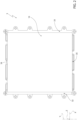
figure 2 is a front view of a casing of a first embodiment of the battery pack according to the invention; -
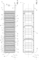
figure 3 is a front view of the battery pack offigure 1 and2 ; -
figure 4 is a cross section along line IV-IV offigure 3 ; -
figure 5 is a top view of the battery pack offigures 1 to 4 ; -
figures 6 and 7 show respective details offigure 4 on a much larger scale; -
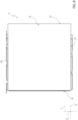
figure 8 is a front view of a casing of a second embodiment of the battery pack according to the invention; -
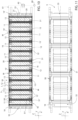
figure 9 is a front view of the battery pack offigure 8 ; -
figure 10 is a cross section along line X-X offigure 9 ; -
figure 11 is a bottom view of the battery pack offigures 8 to 10 ; -
figure 12 shows a detail offigure 10 on a much larger scale; and -
figures 13 and 14 show the trend of the force exerted by the cells upon the containing elements of the battery pack as the thickness of the cells varies, with reference to a known solution and to this invention, respectively. - With reference to
Figure 1 , number 1 indicates, as a whole, a road vehicle provided with twofront wheels 2 and with tworear wheels 3. The road vehicle 1 is an at least partially electric vehicle and is provided with aframe 4. The road vehicle 1 comprises abattery pack 5, in this example supported by theframe 4 inside anengine compartment 6. - In the embodiment shown herein, the
battery pack 5 is arranged at the back of apassenger compartment 7, for example in the area of a vehicle floorboard, behind the seats contained inside thepassenger compartment 7. - With reference to
figures 2 to 7 , thebattery pack 5 basically comprises: - a
casing 10; and - a plurality of
cells casing 10 and connected to one another in series and in parallel so as to obtain the desired total voltage and energy density. - In particular, the
cells - Each
cell - More in detail, the
casing 10 has the shape of a parallelepiped. - The
casing 10 has a length along a direction Y, a width along a direction X orthogonal to the direction Y and a height along a direction Z orthogonal to the directions Z, Y. - In particular, the height of the
casing 10 is smaller than the length and width of thecasing 10. - Similarly, each
cell - In particular, the thickness L of each
cell same cell 11 along the respective directions Y, Z. Thecasing 10 is delimited by: - a pair of
walls Figure 4 ); - a pair of
walls walls 30, 31 (Figure 3 ); and - a pair of
walls walls walls 32, 33 (Figure 3 ). - The
walls - Following the electrochemical reaction performed, the thickness L of the
cells cells cells - The
battery pack 5 comprises (Figures 3 and4 ), in addition: - a plurality of
compensation elements 15 cooperating with thecells cells - a plurality of
layers 16 made of a material resistant to high temperature and thermal shock, for example mica, lying on a plane substantially orthogonal to the direction X and spaced apart from one another along the direction X; and - a plurality of
heat dissipation elements 17 made of a thermally conductor material, for example fins, mainly lying on a plane orthogonal to the direction X and spaced apart from one another along the direction X. - The
cells compensation elements 15, thelayers 16 and theelements 17 define amodular structure 18 housed inside thecasing 10. - More in detail, the
modular structure 18 comprises a plurality of modules M sequentially repeated along the direction X. - Each module M comprises, proceeding along the direction X:
- a
cell 11; - a
layer 16; - a
compensation element 15; - a
cell 12; and - an
element 17. - With reference to
Figure 6 , eachlayer 16 comprises respective end edges 22 opposite one another along the direction Y and fixed to thecasing 10. - Following the increase in the thickness L of the
cells compensation element 15 also has a thickness S along the direction X that is variable between a maximum value Sbol and a minimum value Seol assumed at a minimum value Fbol and a maximum value Feol, respectively, of the force F. - In particular, the minimum value Fbol of the force F corresponds to the maximum value Sbol of the thickness S of the
compensation elements 15 and to the minimum value Lbol of the thickness L of thecells compensation elements 15 and to the maximum value Leol of the thickness L of thecells - Advantageously, each
compensation element 15 is configured to plastically deform itself when it is subjected to a predetermined value FS of compression force F, which is greater than or equal the minimum value Fbol and is smaller than the maximum value Feol, so as to plastically reduce the thickness S for values of said force F exceeding said predetermined value FS. - In the specific case shown herein, the value FS of the force F is greater than the minimum value Fbol.
- In this way, each
compensation element 15 elastically reduces its thickness S when subjected to a compression force F comprised between the minimum value Fbol and the value FS and plastically reduces its thickness S when subjected to a compression force F comprised between the value FS and the maximum value Feol. - In the specific case shown herein, the ratio between the maximum value Feol and the minimum value Fbol is smaller than two, in particular smaller than or equal to 1.5.
- Each
compensation element 15 comprises, in particular: - a pair of
walls 20 parallel to one another, respectively lying orthogonally to the direction X and spaced apart from one another along the direction X; and - a
body 21 interposed between thewalls 20 along the direction X. - With reference to
Figure 7 , thewalls 20 are spaced apart along the direction Z from thewalls - The
body 21 comprises, in turn, respective rounded ends 50, protruding from thewalls walls - In the specific case shown herein, each
compensation element 15 is made of a porous material. Alternatively, eachcompensation element 15 is made of a metal material. - In particular, each
element 17 comprises, in turn (Figure 6 ): - a
main portion 40 lying on a plane orthogonal to the X direction; and - a pair of
ends 41 opposite one another along the direction Z and bent from themain portion 40 towards thewall 33 orthogonally to the direction Z. - The
battery pack 5 preferably comprises (Figure 4 ): - a pump 60 (only schematically shown);
- a feeding circuit 61 (also only schematically shown) for a cooling heat transfer fluid configured to feed the fluid into the
bodies 21 of thecompensation elements 15 at a lower temperature; and - a heat exchanger 62 (also only schematically shown) designed to cool the heat transfer fluid heated by the
bodies 21. - In the specific case shown herein, the heat transfer fluid is a liquid under pressure.
- In use, the
cells battery pack 5 through an electrochemical reaction that takes place in the respective anode and cathode. - During the operation of the
cells compensation elements 15 ensure a level of force F parallel to the direction X and, hence, of even pressure on thecells - Following the operation, the thickness L of the
cells compensation elements 15 that increases from the minimum value Fbol to the maximum value Feol, as shown inFigure 14 . - This increase in thickness L determines a reduction in the thickness S of the
compensation elements 15 from a maximum value Sbol to a minimum value Seol reached at the minimum value Fbol and at the maximum value Feol, respectively (Figure 14 ). - The variation in the thickness S of the
compensation elements 15 occurs by elastic deformation between the minimum force value Fbol and the value FS and by plastic deformation between the value FS and the maximum force value Feol (Figure 14 ) . - At the same time, the
elements 17 thermally dissipate the heat generated by the operation of thecells layers 16 ensure resistance to uncontrolled increases in temperature and to thermal shocks deriving therefrom. - The
circuit 61 feeds the heat transfer fluid into thebodies 21 of thecompensation elements 15 so as to cool therespective elements 17. - With reference to
Figures 8 a 12, number 5' indicates a battery pack according to a further embodiment of the invention. - The battery pack 5' is similar to the
battery pack 5 and will be described below only to the extent that it differs from the latter; equal or equivalent parts of the battery packs 5, 5' will be indicated, when possible, with the same reference numbers. - More in detail, the battery pack 5' differs from the
battery pack 5 in that it does not comprise theelements 17 and in that the walls 20' are made of a thermally conductor material. - The walls 20' are designed to dissipate the heat generated by the operation of the
cells - The walls 20' have respective ends 50' shaped like bellows and connected to
respective walls casing 10. - The module M' of the battery pack 5' differs from the module M of the
battery pack 5 in that it comprises (Figure 10 ) : - a
respective layer 16; - a
respective cell 11; - a
respective compensation element 15; and - a
respective cell 12. - The operation of the battery pack 5' is similar to the one of the
battery pack 5 and, therefore, it is described in detail only as far as it differs from it. - In particular, the walls 20' of the compensation elements 15' dissipate the heat generated by the operation of the
cells elements 17 of thebattery pack 5. - The features of the battery packs 5, 5' and of the method according to the invention reveal evident advantages that can be obtained using them.
- In particular, each
compensation element 15, 15' plastically collapses when the force F exerted by thecells - Consequently, each
compensation element 15, 15' plastically reduces its thickness S for values of said force F greater than said predetermined value FS. - In this way, the force values F exchanged between the
compensation elements 15, 15' and thecells Figures 13 and 14 . - For example, the ratio between the maximum value Feol and the minimum value Fbol of the forces is equal to 1.5 for the
battery pack 5, 5' and equal to 10 in the known solutions described in the introduction to this description (Figure 13 ) . - Therefore, the dimensions, weights and costs of the compensating
elements 15, 15' and, hence, of theentire battery pack 5, 5' can be reduced. - Moreover, the porous or metal material of the
compensation element 15, 15' compensates, during the assembly phase, for unavoidable tolerances between the various components. By so doing, the compression exerted by the compensatingelements 10, 10' upon theindividual cells - The walls 20' of the compensation element 15' are designed to dissipate the heat generated by the operation of the
cells - In this way, the compensation elements 15' help limit any uncontrolled temperature increases and thermal shocks deriving from the operation of the
cells additional elements 17 in addition to the compensation elements 15'. - The
circuit 61 feeds the heat transfer fluid into thebodies 21 so as to cool therespective compensation elements 15, 15' and further reduce the risk of uncontrolled temperature increases and thermal shocks deriving from the operation of thecells - Finally, the
battery pack 5, 5' and the method disclosed and shown herein can be subject to changes and variants, which do not go beyond the scope of protection set forth in the appended claims. - In particular, the value FS of the compression force F could be equal to the minimum value Fbol and smaller than the maximum value Feol.
- In this way, each
compensation element 15 plastically reduces its thickness S when subjected to a compression force F comprised between the minimum value Fbol and the maximum value Feol.
Claims (11)
- A battery pack (5, 5') for an electric road vehicle (1), comprising:- at least one first electrochemical cell (11, 12) comprising, in turn, a cathode, an anode and a solid electrolyte electrically connected to said cathode and anode;the first cell (11, 12) having a first thickness (L) along a direction (X) increasing, in use, following the activation of said first cell (11);- a first compensation element (15, 15') cooperating with said first cell (11, 12) along said direction (X) so as to be subjected, in use, to a compression force (F), which is variable along said direction (X) between a minimum value (Fbol) and a maximum value (Feol); said compensation element (15, 15') having a second thickness (s) along said direction (X), which is variable between a maximum value (Sbol) and a minimum value (Seol) reached at said minimum value (Fbol) and at said maximum value (Feol), respectively;said first compensation element (15, 15') being configured to plastically deform itself when it is subjected, in use, to a predetermined value (FS) of said compression force (F), which is greater than or equal said minimum value (Fbol) and is smaller than said maximum value (Feol), so as to plastically reduce said second thickness (s) for values of said force (F) exceeding said predetermined value (FS);characterized in that it comprises a feeding circuit (61) designed to feed a fluid under pressure into said compensation element (15, 15') so as to dissipate the heat generated, in use, by the activation of said first cell (11, 12) .
- The battery pack according to claim 1, characterized in that said compensation element (15, 15') is made of a porous material.
- The battery pack according to claim 1, characterized in that said compensation element (15, 15') is made of a metal material.
- The battery pack according to any one of the preceding claims, characterized in that it comprises a support (10) accommodating said first cell (11, 12) and said first compensation element (15, 15'), and in that said first compensation element (15, 15') comprises, in turn:- a pair of walls (20) spaced apart from one another and orthogonal to said direction (X); and- a body (21) interposed between said walls (20) along said direction (X).
- The battery pack according to any one of the preceding claims, characterized in that it comprises a second electrochemical cell (12, 11) immediately consecutive to said first electrochemical cell (11, 12) along said first direction (X);said first compensation element (15) being interposed, along said direction (X), between said first and second cell (11, 12);said battery pack (5) further comprising:- a third cell (11, 12) immediately consecutive to said second cell (12, 11) along said first direction (X); and- an element (17), which is made of a heat conductor material, is distinct from said first compensation element (15), is interposed between said second and third cell (12, 11; 11, 12) and is designed to dissipate the heat generated, in use, by said battery pack (5).
- The battery pack according to claim 5, when it depends on claim 4, characterized in that said walls (20) have respective end edges (19), which are opposite one another along a direction (Y) transverse to said first direction (X) and are spaced apart by said support (10);
said body (21) projecting along said second direction (Y) relative to said walls (20). - The battery pack according to any one of the claims from 4 to 6, characterized in that said walls (20') of said compensation element (15') are made of a heat conductor material and are designed to dissipate the heat generated, in use, by said battery pack (5').
- The battery pack according to claim 7, characterized in that said walls (20') are constrained to said support (11) by means of a pair of ends (50') shaped like a bellows.
- An electric or hybrid road vehicle (1), comprising a battery pack (5, 5') according to any one of the preceding claims.
- A method for the compensation of the variation of a first thickness (L) along a direction (X) of an electrochemical cell (11, 12) for a battery pack (5, 5') for an electric or hybrid road vehicle (1);- said cell (11, 12) comprising, in turn, a cathode, an anode and a solid electrolyte electrically connected to said cathode and anode;said method comprising the steps of:i) activating said cell (11, 12) so as to determine an increase in said first thickness (L) of the cell (11, 12) along said direction (X) increasing, in use, following the activation of said cell (11, 12); andii) varying a second thickness (s) along said direction (X) of a compensation element (15, 15') cooperating with said cell (11, 12) between a maximum value (Sbol) and a minimum value (Seol) reached at a minimum value (Fbol) and at a maximum value (Feol), respectively, of a variable compression force (F) exerted by said cell (11, 12) upon said compensation element (15, 15');characterized in that it comprises the step iii) of reducing, through plastic deformation, said second thickness (s) for values of said force (F) exceeding a predetermined value (FS) of said compression force (F); said predetermined value (FS) being greater than or equal to said minimum value (Fbol) and being smaller than said maximum value (Feol).
- The method according to claim 10, characterized in that it comprises the step iv) of feeding a fluid under pressure into said compensation element (15, 15') so as to cool said cell (11, 12).
Applications Claiming Priority (1)
| Application Number | Priority Date | Filing Date | Title |
|---|---|---|---|
| IT102023000021093A IT202300021093A1 (en) | 2023-10-11 | 2023-10-11 | BATTERY PACK FOR AN ELECTRIC-POWERED ROAD VEHICLE AND METHOD OF COMPENSATING FOR THE CHANGE IN THICKNESS OF AN ELECTROCHEMICAL CELL FOR SUCH BATTERY PACK |
Publications (1)
| Publication Number | Publication Date |
|---|---|
| EP4539189A1 true EP4539189A1 (en) | 2025-04-16 |
Family
ID=89321661
Family Applications (2)
| Application Number | Title | Priority Date | Filing Date |
|---|---|---|---|
| EP24205160.5A Pending EP4539190A1 (en) | 2023-10-11 | 2024-10-08 | Battery pack for an electric road vehicle and method for the compensation of the thickness variation of an electrochemical cell for said battery pack |
| EP24205155.5A Pending EP4539189A1 (en) | 2023-10-11 | 2024-10-08 | Battery pack for an electric road vehicle and method for the compensation of the thickness variation of an electrochemical cell for said battery pack |
Family Applications Before (1)
| Application Number | Title | Priority Date | Filing Date |
|---|---|---|---|
| EP24205160.5A Pending EP4539190A1 (en) | 2023-10-11 | 2024-10-08 | Battery pack for an electric road vehicle and method for the compensation of the thickness variation of an electrochemical cell for said battery pack |
Country Status (5)
| Country | Link |
|---|---|
| US (1) | US20250125401A1 (en) |
| EP (2) | EP4539190A1 (en) |
| JP (1) | JP2025066668A (en) |
| CN (1) | CN119812627A (en) |
| IT (1) | IT202300021093A1 (en) |
Citations (2)
| Publication number | Priority date | Publication date | Assignee | Title |
|---|---|---|---|---|
| DE102019108371A1 (en) * | 2019-04-01 | 2020-10-01 | Bayerische Motoren Werke Aktiengesellschaft | High-voltage battery with battery cell swell sensor and motor vehicle |
| US20230135785A1 (en) * | 2021-01-11 | 2023-05-04 | Lg Energy Solution, Ltd. | Battery module including swelling relief unit |
-
2023
- 2023-10-11 IT IT102023000021093A patent/IT202300021093A1/en unknown
-
2024
- 2024-10-04 US US18/906,585 patent/US20250125401A1/en active Pending
- 2024-10-08 EP EP24205160.5A patent/EP4539190A1/en active Pending
- 2024-10-08 EP EP24205155.5A patent/EP4539189A1/en active Pending
- 2024-10-09 CN CN202411400490.4A patent/CN119812627A/en active Pending
- 2024-10-09 JP JP2024176853A patent/JP2025066668A/en active Pending
Patent Citations (2)
| Publication number | Priority date | Publication date | Assignee | Title |
|---|---|---|---|---|
| DE102019108371A1 (en) * | 2019-04-01 | 2020-10-01 | Bayerische Motoren Werke Aktiengesellschaft | High-voltage battery with battery cell swell sensor and motor vehicle |
| US20230135785A1 (en) * | 2021-01-11 | 2023-05-04 | Lg Energy Solution, Ltd. | Battery module including swelling relief unit |
Also Published As
| Publication number | Publication date |
|---|---|
| CN119812627A (en) | 2025-04-11 |
| US20250125401A1 (en) | 2025-04-17 |
| JP2025066668A (en) | 2025-04-23 |
| EP4539190A1 (en) | 2025-04-16 |
| IT202300021093A1 (en) | 2025-04-11 |
Similar Documents
| Publication | Publication Date | Title |
|---|---|---|
| EP3614453B1 (en) | Battery module and battery pack including same | |
| EP3748722B1 (en) | Battery pack comprising mounting structure | |
| KR101597663B1 (en) | Power storage cell with thermal conduction plate | |
| CN109888137B (en) | Battery pack structure of vehicle | |
| EP3989341B1 (en) | Battery pack with fixing bar, and electronic device and automobile comprising same | |
| EP4557454A1 (en) | Battery top cover, battery and electric device | |
| EP1492135B1 (en) | Electric double-layer capacitor | |
| EP4475253A1 (en) | Battery and electric device | |
| CN118738646A (en) | Battery systems and power devices | |
| EP4539189A1 (en) | Battery pack for an electric road vehicle and method for the compensation of the thickness variation of an electrochemical cell for said battery pack | |
| EP4574537A1 (en) | Battery pack for an electrically driven road vehicle and method for compensating the tickness variation of an electrochemical cell for the battery pack | |
| US20250192280A1 (en) | Battery pack for an electric road vehicle and method for the compensation of the thickness variation of an electrochemical cell for said battery pack | |
| EP4632899A1 (en) | Battery system with improved end plate | |
| EP4632900A1 (en) | Battery system with improved end spacer | |
| EP4632901A1 (en) | Battery system with improved cell stack frame | |
| CN223058790U (en) | Bracket for battery pack, battery pack with bracket and vehicle with battery pack | |
| US12388141B2 (en) | Battery pack | |
| EP4564554A1 (en) | Battery module and battery pack including the same | |
| CN223230459U (en) | Battery device and electric equipment | |
| EP4068451A1 (en) | Power storage device | |
| EP4614675A1 (en) | Battery module | |
| US20260121253A1 (en) | Secondary battery | |
| EP4579882A1 (en) | Battery and electrical apparatus | |
| EP4614695A1 (en) | Battery system with compensator | |
| CN121642305A (en) | Battery cells, battery packs and vehicles |
Legal Events
| Date | Code | Title | Description |
|---|---|---|---|
| PUAI | Public reference made under article 153(3) epc to a published international application that has entered the european phase |
Free format text: ORIGINAL CODE: 0009012 |
|
| STAA | Information on the status of an ep patent application or granted ep patent |
Free format text: STATUS: THE APPLICATION HAS BEEN PUBLISHED |
|
| AK | Designated contracting states |
Kind code of ref document: A1 Designated state(s): AL AT BE BG CH CY CZ DE DK EE ES FI FR GB GR HR HU IE IS IT LI LT LU LV MC ME MK MT NL NO PL PT RO RS SE SI SK SM TR |
|
| STAA | Information on the status of an ep patent application or granted ep patent |
Free format text: STATUS: REQUEST FOR EXAMINATION WAS MADE |
|
| 17P | Request for examination filed |
Effective date: 20250922 |