EP4539182A1 - Curved battery and electronic device comprising same - Google Patents
Curved battery and electronic device comprising same Download PDFInfo
- Publication number
- EP4539182A1 EP4539182A1 EP24767985.5A EP24767985A EP4539182A1 EP 4539182 A1 EP4539182 A1 EP 4539182A1 EP 24767985 A EP24767985 A EP 24767985A EP 4539182 A1 EP4539182 A1 EP 4539182A1
- Authority
- EP
- European Patent Office
- Prior art keywords
- positive electrode
- electrode plate
- negative electrode
- tab
- electrode
- Prior art date
- Legal status (The legal status is an assumption and is not a legal conclusion. Google has not performed a legal analysis and makes no representation as to the accuracy of the status listed.)
- Pending
Links
Images






Classifications
-
- H—ELECTRICITY
- H01—ELECTRIC ELEMENTS
- H01M—PROCESSES OR MEANS, e.g. BATTERIES, FOR THE DIRECT CONVERSION OF CHEMICAL ENERGY INTO ELECTRICAL ENERGY
- H01M10/00—Secondary cells; Manufacture thereof
- H01M10/04—Construction or manufacture in general
- H01M10/0431—Cells with wound or folded electrodes
-
- H—ELECTRICITY
- H01—ELECTRIC ELEMENTS
- H01M—PROCESSES OR MEANS, e.g. BATTERIES, FOR THE DIRECT CONVERSION OF CHEMICAL ENERGY INTO ELECTRICAL ENERGY
- H01M50/00—Constructional details or processes of manufacture of the non-active parts of electrochemical cells other than fuel cells, e.g. hybrid cells
- H01M50/10—Primary casings; Jackets or wrappings
- H01M50/102—Primary casings; Jackets or wrappings characterised by their shape or physical structure
- H01M50/107—Primary casings; Jackets or wrappings characterised by their shape or physical structure having curved cross-section, e.g. round or elliptic
-
- H—ELECTRICITY
- H01—ELECTRIC ELEMENTS
- H01M—PROCESSES OR MEANS, e.g. BATTERIES, FOR THE DIRECT CONVERSION OF CHEMICAL ENERGY INTO ELECTRICAL ENERGY
- H01M50/00—Constructional details or processes of manufacture of the non-active parts of electrochemical cells other than fuel cells, e.g. hybrid cells
- H01M50/50—Current conducting connections for cells or batteries
- H01M50/531—Electrode connections inside a battery casing
- H01M50/533—Electrode connections inside a battery casing characterised by the shape of the leads or tabs
-
- H—ELECTRICITY
- H01—ELECTRIC ELEMENTS
- H01M—PROCESSES OR MEANS, e.g. BATTERIES, FOR THE DIRECT CONVERSION OF CHEMICAL ENERGY INTO ELECTRICAL ENERGY
- H01M50/00—Constructional details or processes of manufacture of the non-active parts of electrochemical cells other than fuel cells, e.g. hybrid cells
- H01M50/50—Current conducting connections for cells or batteries
- H01M50/531—Electrode connections inside a battery casing
- H01M50/536—Electrode connections inside a battery casing characterised by the method of fixing the leads to the electrodes, e.g. by welding
-
- Y—GENERAL TAGGING OF NEW TECHNOLOGICAL DEVELOPMENTS; GENERAL TAGGING OF CROSS-SECTIONAL TECHNOLOGIES SPANNING OVER SEVERAL SECTIONS OF THE IPC; TECHNICAL SUBJECTS COVERED BY FORMER USPC CROSS-REFERENCE ART COLLECTIONS [XRACs] AND DIGESTS
- Y02—TECHNOLOGIES OR APPLICATIONS FOR MITIGATION OR ADAPTATION AGAINST CLIMATE CHANGE
- Y02E—REDUCTION OF GREENHOUSE GAS [GHG] EMISSIONS, RELATED TO ENERGY GENERATION, TRANSMISSION OR DISTRIBUTION
- Y02E60/00—Enabling technologies; Technologies with a potential or indirect contribution to GHG emissions mitigation
- Y02E60/10—Energy storage using batteries
-
- Y—GENERAL TAGGING OF NEW TECHNOLOGICAL DEVELOPMENTS; GENERAL TAGGING OF CROSS-SECTIONAL TECHNOLOGIES SPANNING OVER SEVERAL SECTIONS OF THE IPC; TECHNICAL SUBJECTS COVERED BY FORMER USPC CROSS-REFERENCE ART COLLECTIONS [XRACs] AND DIGESTS
- Y02—TECHNOLOGIES OR APPLICATIONS FOR MITIGATION OR ADAPTATION AGAINST CLIMATE CHANGE
- Y02P—CLIMATE CHANGE MITIGATION TECHNOLOGIES IN THE PRODUCTION OR PROCESSING OF GOODS
- Y02P70/00—Climate change mitigation technologies in the production process for final industrial or consumer products
- Y02P70/50—Manufacturing or production processes characterised by the final manufactured product
Definitions
- the disclosure relates to a curved battery capable of maintaining a bent shape and an electronic device including the same.
- An electronic device may refer to a device that performs a predetermined function according to a program installed therein, such as an augmented reality (AR) device, a virtual reality (VR) device, a mixed reality (MR) device, an extended reality (XR) device, a smartphone, a tablet personal computer (PC), a wearable electronic device, a smartwatch, a home appliance, an electronic notebook, a portable multimedia player, a mobile communication terminal, a tablet PC, a video/audio device, a desktop/laptop computer, or a vehicle navigation system.
- AR augmented reality
- VR virtual reality
- MR mixed reality
- XR extended reality
- smartphone a tablet personal computer
- PC tablet personal computer
- a wearable electronic device e.g., a smartwatch, a home appliance, an electronic notebook, a portable multimedia player, a mobile communication terminal, a tablet PC, a video/audio device, a desktop/laptop computer, or a vehicle navigation system.
- These electronic devices may include a battery for driving (
- the secondary battery can be repeatedly charged and discharged, and the use of secondary batteries is increasing because they are economical and environmentally friendly.
- the types and shapes of electronic devices using secondary batteries have become more diverse, and the shapes of the batteries should be changed to match the shapes of the electronic devices.
- An electronic device having a curved surface shape may be equipped with a battery that is bent to match the shape of the inner space of the electronic device (e.g., a curved battery).
- Curved batteries have the characteristic of being restored (e.g., unfolded) to their original plat shape over time due to the restoring force of a first electrode plate (e.g., a positive electrode plate, a positive electrode layer, or a positive electrode film), a second electrode plate (e.g., a negative electrode plate, a negative electrode layer, or a negative electrode film), and a separator (e.g., a separation plate or a separation layer).
- An embodiment of the disclosure may provide a curved (or non-flat, non-planar, arcuate, or bent) battery that is capable of maintaining a bent (or curved, non-flat, non-planar, or arcuate) shape and an electronic device including the same.
- a curved (or non-flat, non-planar, arcuate, or bent) battery may include a battery cell having a curved (or non-rectangular, arcuate, or bent (i.e. including at least one bend)) cross-section, and a housing disposed outside the battery cell.
- the battery cell may include a positive electrode plate, a negative electrode plate, a separator disposed between the positive electrode plate and the negative electrode plate, a first electrode tab electrically connected to at least a portion of the positive electrode plate, and a second electrode tab electrically connected to at least a portion of the negative electrode plate.
- the positive electrode plate, the negative electrode plate, and the separator may be wound and disposed (or, in other words, they may be wound or rolled together in a wound or rolled configuration or arrangement, having a spiral cross section, for example comprising a plurality of turns or layers). At least one of the first electrode tab and the second electrode tab may be arranged to correspond to the length of the battery cell.
- An electronic device may include a flexible display, a display driver integrated circuit (IC) configured to drive the flexible display, a processor configured to control the operation of the display driver IC, memory operatively connected to the processor, and a battery configured to supply power to the display driver IC and the processor.
- the battery may include a battery cell having a curved (or non-rectangular, arcuate, or bent) cross-section, and a housing disposed outside the battery cell.
- the battery cell may include a positive electrode plate, a negative electrode plate, a separator disposed between the positive electrode plate and the negative electrode plate, a first electrode tab electrically connected to at least a portion of the positive electrode plate, and a second electrode tab electrically connected to at least a portion of the negative electrode plate.
- the positive electrode plate, the negative electrode plate, and the separator may be wound and disposed (or, in other words, they may be wound or rolled together in a wound or rolled configuration or arrangement, having a spiral cross section, for example comprising a plurality of turns or layers). At least one of the first electrode tab and the second electrode tab may be arranged to correspond to the length of the battery cell.
- a curved (or non-flat, non-planar, arcuate, or bent) battery may include a battery cell having a curved (or non-flat, non-planar, arcuate, or bent) shape, and at least one support member arranged to support said battery cell to maintain said shape.
- the at least one support member may be arranged to support the battery cell in said shape, for example so as to resist a change in shape that could otherwise result from a resilience of the battery cell urging the battery cell to return to a previous state or shape (such as a flat, non-curved, planar, straight, or unbent shape).
- the at least one support member may be an electrode tab electrically connected to a component of the battery cell (e.g.
- the at least one support member may have a curved (or non-flat, non-planar, arcuate, or bent) shape, for example corresponding to the shape of the battery cell).
- the at least one support member may comprise a ductile material (for example a metal), and at least a portion of the at least one support member may be work-hardened (for example by bending).
- The, or each, work-hardened portion of the at least one support member may comprise at least one of a notch, groove, hole, or perforation arranged to reduce a cross-sectional area of the respective support member.
- the battery cell may, for example, comprise a positive electrode plate, a negative electrode plate, and a separator disposed between the positive electrode plate and the negative electrode plate, these three components being wound or rolled together (e.g. around a winding or rolling axis) in a wound or rolled configuration or arrangement, having a spiral cross section, for example comprising a plurality of turns or layers.
- This spiral cross section may also be curved, arcuate, or bent, and the at least one support member may be arranged to support the battery cell against (i.e.
- At least one support member may be arranged to extend in a direction perpendicular to the winding or rolling axis or plane, and may be arranged to support the battery cell along at least a portion (e.g. 50% to 100%) of a length of the battery cell's cross section.
- An electronic device may include a flexible display, a display driver integrated circuit (IC) configured to drive the flexible display, a processor configured to control the operation of the display driver IC, memory operatively connected to the processor, and a battery configured to supply power to the display driver IC and the processor, the battery being in accordance with any one of the embodiments disclosed in the preceding paragraph.
- IC display driver integrated circuit
- a curved battery according to an embodiment of the disclosure is capable of maintaining a bent shape.
- a curved battery according to an embodiment of the disclosure is configured such that at least one of the first electrode tab and the second electrode tab corresponds to the length of the battery cell.
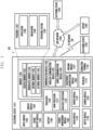
- Fig. 1 is a block diagram illustrating an electronic device 101 in a network environment 100 according to various embodiments.
- the electronic device 101 in the network environment 100 may communicate with an electronic device 102 via a first network 198 (e.g., a short-range wireless communication network), or at least one of an electronic device 104 or a server 108 via a second network 199 (e.g., a long-range wireless communication network).
- a first network 198 e.g., a short-range wireless communication network
- a second network 199 e.g., a long-range wireless communication network
- the electronic device 101 may communicate with the electronic device 104 via the server 108.
- the processor 120 may include a main processor 121 (e.g., a central processing unit (CPU) or an application processor (AP)), or an auxiliary processor 123 (e.g., a graphics processing unit (GPU), a neural processing unit (NPU), an image signal processor (ISP), a sensor hub processor, or a communication processor (CP)) that is operable independently from, or in conjunction with, the main processor 121.
- a main processor 121 e.g., a central processing unit (CPU) or an application processor (AP)
- auxiliary processor 123 e.g., a graphics processing unit (GPU), a neural processing unit (NPU), an image signal processor (ISP), a sensor hub processor, or a communication processor (CP)
- the main processor 121 may be adapted to consume less power than the main processor 121, or to be specific to a specified function.
- the auxiliary processor 123 may be implemented as separate from, or as part of the main processor 121.
- the auxiliary processor 123 may control at least some of functions or states related to at least one component (e.g., the display module 160, the sensor module 176, or the communication module 190) among the components of the electronic device 101, instead of the main processor 121 while the main processor 121 is in an inactive (e.g., sleep) state, or together with the main processor 121 while the main processor 121 is in an active state (e.g., executing an application).
- the auxiliary processor 123 e.g., an image signal processor or a communication processor
- the auxiliary processor 123 may include a hardware structure specified for artificial intelligence model processing.
- An artificial intelligence model may be generated by machine learning. Such learning may be performed, e.g., by the electronic device 101 where the artificial intelligence is performed or via a separate server (e.g., the server 108). Learning algorithms may include, but are not limited to, e.g., supervised learning, unsupervised learning, semi-supervised learning, or reinforcement learning.
- the artificial intelligence model may include a plurality of artificial neural network layers.
- the artificial neural network may be a deep neural network (DNN), a convolutional neural network (CNN), a recurrent neural network (RNN), a restricted boltzmann machine (RBM), a deep belief network (DBN), a bidirectional recurrent deep neural network (BRDNN), deep Q-network or a combination of two or more thereof but is not limited thereto.
- the artificial intelligence model may, additionally or alternatively, include a software structure other than the hardware structure.
- the memory 130 may store various data used by at least one component (e.g., the processor 120 or the sensor module 176) of the electronic device 101.
- the various data may include, for example, software (e.g., the program 140) and input data or output data for a command related thererto.
- the memory 130 may include the volatile memory 132 or the non-volatile memory 134.
- the program 140 may be stored in the memory 130 as software, and may include, for example, an operating system (OS) 142, middleware 144, or an application 146.
- OS operating system
- middleware middleware
- application application
- the input module 150 may receive a command or data to be used by another component (e.g., the processor 120) of the electronic device 101, from the outside (e.g., a user) of the electronic device 101.
- the input module 150 may include, for example, a microphone, a mouse, a keyboard, a key (e.g., a button), or a digital pen (e.g., a stylus pen).
- the sound output module 155 may output sound signals to the outside of the electronic device 101.
- the sound output module 155 may include, for example, a speaker or a receiver.
- the speaker may be used for general purposes, such as playing multimedia or playing record.
- the receiver may be used for receiving incoming calls. According to an embodiment, the receiver may be implemented as separate from, or as part of the speaker.
- the display module 160 may visually provide information to the outside (e.g., a user) of the electronic device 101.
- the display module 160 may include, for example, a display, a hologram device, or a projector and control circuitry to control a corresponding one of the display, hologram device, and projector.
- the display module 160 may include a touch sensor adapted to detect a touch, or a pressure sensor adapted to measure the intensity of force incurred by the touch.
- the audio module 170 may convert a sound into an electrical signal and vice versa. According to an embodiment, the audio module 170 may obtain the sound via the input module 150, or output the sound via the sound output module 155 or a headphone of an external electronic device (e.g., an electronic device 102) directly (e.g., wiredly) or wirelessly coupled with the electronic device 101.
- an external electronic device e.g., an electronic device 102
- directly e.g., wiredly
- wirelessly e.g., wirelessly
- the sensor module 176 may detect an operational state (e.g., power or temperature) of the electronic device 101 or an environmental state (e.g., a state of a user) external to the electronic device 101, and then generate an electrical signal or data value corresponding to the detected state.
- the sensor module 176 may include, for example, a gesture sensor, a gyro sensor, an atmospheric pressure sensor, a magnetic sensor, an acceleration sensor, a grip sensor, a proximity sensor, a color sensor, an infrared (IR) sensor, a biometric sensor, a temperature sensor, a humidity sensor, or an illuminance sensor.
- the interface 177 may support one or more specified protocols to be used for the electronic device 101 to be coupled with the external electronic device (e.g., the electronic device 102) directly (e.g., wiredly) or wirelessly.
- the interface 177 may include, for example, a high definition multimedia interface (HDMI), a universal serial bus (USB) interface, a secure digital (SD) card interface, or an audio interface.
- HDMI high definition multimedia interface
- USB universal serial bus
- SD secure digital
- the haptic module 179 may convert an electrical signal into a mechanical stimulus (e.g., a vibration or a movement) or electrical stimulus which may be recognized by a user via his tactile sensation or kinesthetic sensation.
- the haptic module 179 may include, for example, a motor, a piezoelectric element, or an electric stimulator.
- the camera module 180 may capture a still image or moving images.
- the camera module 180 may include one or more lenses, image sensors, image signal processors, or flashes.
- the power management module 188 may manage power supplied to the electronic device 101.
- the power management module 188 may be implemented as at least part of, for example, a power management integrated circuit (PMIC).
- PMIC power management integrated circuit
- the battery 189 may supply power to at least one component of the electronic device 101.
- the battery 189 may include, for example, a primary cell which is not rechargeable, a secondary cell which is rechargeable, or a fuel cell.
- the communication module 190 may support establishing a direct (e.g., wired) communication channel or a wireless communication channel between the electronic device 101 and the external electronic device (e.g., the electronic device 102, the electronic device 104, or the server 108) and performing communication via the established communication channel.
- the communication module 190 may include one or more communication processors that are operable independently from the processor 120 (e.g., the application processor (AP)) and supports a direct (e.g., wired) communication or a wireless communication.
- AP application processor
- a corresponding one of these communication modules may communicate with the external electronic device via the first network 198 (e.g., a short-range communication network, such as BluetoothTM, wireless-fidelity (Wi-Fi) direct, or infrared data association (IrDA)) or the second network 199 (e.g., a long-range communication network, such as a legacy cellular network, a 5G network, a next-generation communication network, the Internet, or a computer network (e.g., LAN or wide area network (WAN)).
- first network 198 e.g., a short-range communication network, such as BluetoothTM, wireless-fidelity (Wi-Fi) direct, or infrared data association (IrDA)
- the second network 199 e.g., a long-range communication network, such as a legacy cellular network, a 5G network, a next-generation communication network, the Internet, or a computer network (e.g., LAN or wide area network (WAN)).
- the wireless communication module 192 may identify and authenticate the electronic device 101 in a communication network, such as the first network 198 or the second network 199, using subscriber information (e.g., international mobile subscriber identity (IMSI)) stored in the subscriber identification module 196.
- subscriber information e.g., international mobile subscriber identity (IMSI)
- the wireless communication module 192 may support a 5G network, after a 4G network, and next-generation communication technology, e.g., new radio (NR) access technology.
- the NR access technology may support enhanced mobile broadband (eMBB), massive machine type communications (mMTC), or ultra-reliable and low-latency communications (URLLC).
- eMBB enhanced mobile broadband
- mMTC massive machine type communications
- URLLC ultra-reliable and low-latency communications
- the wireless communication module 192 may support a high-frequency band (e.g., the mmWave band) to achieve, e.g., a high data transmission rate.
- the wireless communication module 192 may support various technologies for securing performance on a high-frequency band, such as, e.g., beamforming, massive multiple-input and multiple-output (massive MIMO), full dimensional MIMO (FD-MIMO), array antenna, analog beam-forming, or large scale antenna.
- the wireless communication module 192 may support various requirements specified in the electronic device 101, an external electronic device (e.g., the electronic device 104), or a network system (e.g., the second network 199).
- the wireless communication module 192 may support a peak data rate (e.g., 20Gbps or more) for implementing eMBB, loss coverage (e.g., 164dB or less) for implementing mMTC, or U-plane latency (e.g., 0.5ms or less for each of downlink (DL) and uplink (UL), or a round trip of 1ms or less) for implementing URLLC.
- a peak data rate e.g., 20Gbps or more
- loss coverage e.g., 164dB or less
- U-plane latency e.g., 0.5ms or less for each of downlink (DL) and uplink (UL), or a round trip of 1ms or less
- the antenna module 197 may transmit or receive a signal or power to or from the outside (e.g., the external electronic device) of the electronic device 101.
- the antenna module 197 may include an antenna including a radiating element composed of a conductive material or a conductive pattern formed in or on a substrate (e.g., a printed circuit board (PCB)).
- the antenna module 197 may include a plurality of antennas (e.g., array antennas). In such a case, at least one antenna appropriate for a communication scheme used in the communication network, such as the first network 198 or the second network 199, may be selected, for example, by the communication module 190 (e.g., the wireless communication module 192) from the plurality of antennas.
- the signal or the power may then be transmitted or received between the communication module 190 and the external electronic device via the selected at least one antenna.
- another component e.g., a radio frequency integrated circuit (RFIC)
- RFIC radio frequency integrated circuit
- the antenna module 197 may form a mmWave antenna module.
- the mmWave antenna module may include a printed circuit board, a RFIC disposed on a first surface (e.g., the bottom surface) of the printed circuit board, or adjacent to the first surface and capable of supporting a designated high-frequency band (e.g., the mmWave band), and a plurality of antennas (e.g., array antennas) disposed on a second surface (e.g., the top or a side surface) of the printed circuit board, or adjacent to the second surface and capable of transmitting or receiving signals of the designated high-frequency band.
- a RFIC disposed on a first surface (e.g., the bottom surface) of the printed circuit board, or adjacent to the first surface and capable of supporting a designated high-frequency band (e.g., the mmWave band)
- a plurality of antennas e.g., array antennas
- At least some of the above-described components may be coupled mutually and communicate signals (e.g., commands or data) therebetween via an inter-peripheral communication scheme (e.g., a bus, general purpose input and output (GPIO), serial peripheral interface (SPI), or mobile industry processor interface (MIPI)).
- an inter-peripheral communication scheme e.g., a bus, general purpose input and output (GPIO), serial peripheral interface (SPI), or mobile industry processor interface (MIPI)
- commands or data may be transmitted or received between the electronic device 101 and the external electronic device 104 via the server 108 coupled with the second network 199.
- Each of the electronic devices 102 or 104 may be a device of a same type as, or a different type, from the electronic device 101.
- all or some of operations to be executed at the electronic device 101 may be executed at one or more of the external electronic devices 102, 104, or 108. For example, if the electronic device 101 should perform a function or a service automatically, or in response to a request from a user or another device, the electronic device 101, instead of, or in addition to, executing the function or the service, may request the one or more external electronic devices to perform at least part of the function or the service.
- the external electronic device 104 or the server 108 may be included in the second network 199.
- the electronic device 101 may be applied to intelligent services (e.g., smart home, smart city, smart car, or healthcare) based on 5G communication technology or IoT-related technology.
- the electronic device may be one of various types of electronic devices.
- the electronic devices may include, for example, a portable communication device (e.g., a smartphone), a computer device, a portable multimedia device, a portable medical device, a camera, a wearable device, or a home appliance. According to an embodiment of the disclosure, the electronic devices are not limited to those described above.
- each of such phrases as “A or B,” “at least one of A and B,” “at least one of A or B,” “A, B, or C,” “at least one of A, B, and C,” and “at least one of A, B, or C,” may include any one of, or all possible combinations of the items enumerated together in a corresponding one of the phrases.
- such terms as “1st” and “2nd,” or “first” and “second” may be used to simply distinguish a corresponding component from another, and does not limit the components in other aspect (e.g., importance or order).
- an element e.g., a first element
- the element may be coupled with the other element directly (e.g., wiredly), wirelessly, or via a third element.
- module may include a unit implemented in hardware, software, or firmware, and may interchangeably be used with other terms, for example, “logic,” “logic block,” “part,” or “circuitry”.
- a module may be a single integral component, or a minimum unit or part thereof, adapted to perform one or more functions.
- the module may be implemented in a form of an application-specific integrated circuit (ASIC).
- ASIC application-specific integrated circuit
- Various embodiments as set forth herein may be implemented as software (e.g., the program 140) including one or more instructions that are stored in a storage medium (e.g., internal memory 136 or external memory 138) that is readable by a machine (e.g., the electronic device 101).
- a processor e.g., the processor 120
- the machine e.g., the electronic device 101
- the one or more instructions may include a code generated by a compiler or a code executable by an interpreter.
- the machine-readable storage medium may be provided in the form of a non-transitory storage medium.
- non-transitory simply means that the storage medium is a tangible device, and does not include a signal (e.g., an electromagnetic wave), but this term does not differentiate between where data is semi-permanently stored in the storage medium and where the data is temporarily stored in the storage medium.
- a method may be included and provided in a computer program product.
- the computer program product may be traded as a product between a seller and a buyer.
- the computer program product may be distributed in the form of a machine-readable storage medium (e.g., compact disc read only memory (CD-ROM)), or be distributed (e.g., downloaded or uploaded) online via an application store (e.g., PlayStoreTM), or between two user devices (e.g., smart phones) directly. If distributed online, at least part of the computer program product may be temporarily generated or at least temporarily stored in the machine-readable storage medium, such as memory of the manufacturer's server, a server of the application store, or a relay server.
- CD-ROM compact disc read only memory
- an application store e.g., PlayStoreTM
- two user devices e.g., smart phones
- each component e.g., a module or a program of the above-described components may include a single entity or multiple entities, and some of the multiple entities may be separately disposed in different components. According to various embodiments, one or more of the above-described components may be omitted, or one or more other components may be added. Alternatively or additionally, a plurality of components (e.g., modules or programs) may be integrated into a single component. In such a case, according to various embodiments, the integrated component may still perform one or more functions of each of the plurality of components in the same or similar manner as they are performed by a corresponding one of the plurality of components before the integration.
- operations performed by the module, the program, or another component may be carried out sequentially, in parallel, repeatedly, or heuristically, or one or more of the operations may be executed in a different order or omitted, or one or more other operations may be added.
- a display module 160 may include a flexible display configured to be foldable or unfoldable.
- the display module 160 may include a flexible display that is arranged to be slidable (e.g., to be slidable in the x-axis direction and the y-axis direction) to provide a screen (e.g., a display screen).
- the display module 160 may be referred to as a transformable display (e.g., a stretchable display, an expandable display, or a slide-in/out display).
- a transformable display e.g., a stretchable display, an expandable display, or a slide-in/out display.
- the display module 160 may include a display driver IC (DDIC) (e.g., a display driver) configured to drive the display.
- DDIC display driver IC
- the DDIC may receive image information including image data or an image control signal corresponding to a command for controlling the image data from another component of an electronic device (e.g., the electronic device 101 in FIG. 1 ) via an interface module.
- the image information may be received from a processor (e.g., the processor 120 in FIG. 1 ) (e.g., the main processor 121 in FIG. 1 ) (e.g., an application processor), or an auxiliary processor (e.g., the auxiliary processor 123 in FIG. 1 ) (e.g., a graphics processor) operated independently from the function of the main processor 121.
- a processor e.g., the processor 120 in FIG. 1
- the main processor 121 in FIG. 1 e.g., an application processor
- an auxiliary processor e.g., the auxiliary processor 123 in FIG. 1
- a graphics processor operated independently from the function of the main processor 121.
- FIG. 2 is a view illustrating electronic devices having a curved surface shape.
- examples of electronic devices having a curved surface shape include a ring-type electronic device 210 (e.g., a smart ring) (e.g., the electronic device 101 in FIG. 1 ) or a band-type electronic device 220 (e.g., a smart band) (e.g., the electronic device 101 in FIG. 1 ).
- a ring-type electronic device 210 e.g., a smart ring
- a band-type electronic device 220 e.g., a smart band
- the ring-type electronic device 210 may have a circular outer shape 211.
- the ring-type electronic device 210 may include a bent curved battery (e.g., the curved battery 300 of FIG. 3 ) as a battery (e.g., the battery 189 in FIG. 1 ) disposed therein.
- the band-type electronic device 220 may have an oval outer shape 221.
- the band-type electronic device 220 may include a bent curved battery (e.g., the curved battery 300 of FIG. 3 ) as a battery (e.g., the battery 189 in FIG. 1 ) disposed therein.
- the outer shape 221 of the band-type electronic device 220 is not limited to the circular or oval shape, and may be formed in various shapes (e.g., a shape including curves and straight lines).
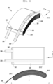
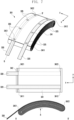
- FIG. 3 is a perspective view illustrating a curved battery according to an embodiment of the disclosure.
- FIG. 4 is an exploded perspective view illustrating the curved battery according to an embodiment of the disclosure.
- the housing 310 may include an inner space, and a battery cell 301 may be disposed in the inner space.
- the housing 310 may include curved surface shapes G1 and G2 depending on the shape of the external shape 211 of the electronic device 210.
- the housing 310 may include an inner space having the curved surface shapes G1 and G2 corresponding to the shapes of surfaces S1 and S2 (e.g., curved surface shapes) of the battery cell 301 (e.g., a battery pouch).
- the battery cell 301 may be disposed in the inner space of the housing 310, and the battery cell 301 may be sealed by the housing 310.
- the surface of the battery cell 301 may include a concave first surface S1 and a convex second surface S2.
- an external pressure may be applied to the battery cell to have the concave first surface S1 and the convex second surface S2.
- the battery cell 301 may have a curved shape when fabricated.
- the concave first surface S1 may be the bottom surface of the battery cell 301
- the convex second surface S2 may be the top surface of the battery cell 301.
- the concave first surface S1 may be the top surface of the battery cell 301
- the convex second surface S2 may be the bottom surface of the battery cell 301.
- the battery cell 301 may include a first electrode plate 341 (e.g., a positive electrode plate, a positive electrode layer, a positive electrode film), a second electrode plate 342 (e.g., a negative electrode plate, a negative electrode layer, or a negative electrode film), a separator 343 (e.g. a separation plate or a separation layer), a first electrode tab 320 (e.g., a first electrode lead, a positive electrode tab, or a positive electrode lead), and a second electrode tab 330 (e.g., a second electrode lead, a negative electrode tab, or a negative electrode lead).
- a first electrode plate 341 e.g., a positive electrode plate, a positive electrode layer, a positive electrode film
- a second electrode plate 342 e.g., a negative electrode plate, a negative electrode layer, or a negative electrode film
- a separator 343 e.g. a separation plate or a separation layer
- a first electrode tab 320 e
- the first electrode tab 320 (e.g., a first electrode lead, a positive electrode tab, or a positive electrode lead) may include not only a portion that overlaps the first electrode plate 341 (e.g., a positive electrode plate, a positive electrode layer, or a positive electrode film), but also a portion exposed to the outside of the housing 310.
- the second electrode tab 330 may include not only a portion that overlaps the second electrode plate 342 (e.g., a negative electrode plate, a negative electrode layer, or a negative electrode film), but also a portion exposed to the outside of the housing 310.
- the first electrode tab 320 e.g., a first electrode lead, a positive electrode tab, or a positive electrode lead
- the second electrode tab 330 e.g., a second electrode lead, a negative electrode tab, or a negative electrode lead
- the first electrode tab 320 may contain a conductive metallic material.
- the separator 343 (e.g., a separation plate or a separation layer) may be disposed between the first electrode plate 341 (e.g., a positive electrode plate, a positive electrode layer, or a positive electrode film) and the second electrode plate 342 (e.g., a negative electrode plate, a negative electrode layer, or a negative electrode film) to electrically separate the first electrode plate 341 (e.g., a positive electrode plate, a positive electrode layer, or a positive electrode film) and the second electrode plate 342 (e.g., a negative electrode plate, a negative electrode layer, or a negative electrode film).
- the first electrode plate 341 e.g., a positive electrode plate, a positive electrode layer, or a positive electrode film
- the second electrode plate 342 e.g., a negative electrode plate, a negative electrode layer, or a negative electrode film
- the first electrode plate 341 e.g., a positive electrode plate, a positive electrode layer, or a positive electrode film
- the second electrode plate 342 e.g., a negative electrode plate, a negative electrode layer, or a negative electrode film
- the first electrode plate 341 e.g., a positive electrode plate, a positive electrode layer, or a positive electrode film
- the second electrode plate 342 e.g., a negative electrode plate, a negative electrode layer, or a negative electrode film
- the battery cell 301 may be wound in the form of a jelly-roll after sequentially stacking the first electrode plate 341 (e.g., a positive electrode plate, a positive electrode layer, or a positive electrode film), the separator 343 (e.g., a separation plate or a separation layer), and the second electrode plate 342 (e.g., a negative electrode plate, a negative electrode layer, or a negative electrode film).
- the first electrode plate, the second electrode plate, and the separator may each initially be in the form of a respective flexible plate, layer, or sheet, and the battery cell may be formed by stacking the three component layers together, then rolling or winding them together about a winding or rolling axis or plane.
- the resultant wound or rolled structure may be described as being in the form of a jelly-roll, or Swiss-roll, and has a spiral or coiled cross section, for example comprising a plurality of turns, windings, or layers.
- the first electrode plate 341 (e.g., a positive electrode plate, a positive electrode layer, or a positive electrode film) may include a first active material portion to which a first active material is applied and a first uncoated portion to which the first active material is not applied.
- the first active material portion may be formed by applying the first active material to a portion of at least one surface of, for example, an aluminum plate, and the remaining portion of the aluminum plate to which the first active material is not applied may become the first uncoated portion.
- the first active material may be a positive-polarizing material and may include a lithium-containing transition metal oxide or a lithium chalcogenide compound, such as LiCoO 2 , LiNiO 2 , LiMnO 2 , or LiMnO 4 .
- a lithium-containing transition metal oxide or a lithium chalcogenide compound such as LiCoO 2 , LiNiO 2 , LiMnO 2 , or LiMnO 4 .
- the second electrode plate 342 may include a second active material portion to which a second active material is applied and a second uncoated portion to which the second active material is not applied.
- the second active material portion may be formed by applying the second active material to a portion of at least one surface of, for example, an aluminum plate (or a copper plate), and the remaining portion of the aluminum plate to which the second active material is not applied may become the second uncoated portion.
- the separator 343 (e.g., a separation plate or a separation layer) may be a porous polymer film such as a polyethylene or polypropylene film.
- the separator 343 (e.g., a separation plate or a separation layer) may be formed as an independent film.
- the separator 343 (e.g., a separation plate or a separation layer) may be formed by forming a non-conductive porous layer on the first electrode plate 341 (e.g., a positive electrode plate, a positive electrode layer, or a positive electrode film) or the second electrode plate 342 (e.g., a negative electrode plate, a negative electrode layer, or a negative electrode film).
- first electrode plate 341 e.g., a positive electrode plate, a positive electrode layer, or a positive electrode film
- the second electrode plate 342 e.g., a negative electrode plate, a negative electrode layer, or a negative electrode film.
- the separator 343 (e.g., a separation plate or a separation layer) may be provided to electrically separate the first electrode plate 341 (e.g., a positive electrode plate, a positive electrode layer, or a positive electrode film) and the second electrode plate 112.
- first electrode plate 341 e.g., a positive electrode plate, a positive electrode layer, or a positive electrode film
- the first electrode tab 320 e.g., a first electrode lead, a positive electrode tab, or a positive electrode lead
- the second electrode tab 330 e.g., a second electrode lead, a negative electrode tab, or a negative electrode lead
- the first electrode tab 320 e.g., a first electrode lead, a positive electrode tab, or a positive electrode lead
- the second electrode tab 330 e.g., a second electrode lead, a negative electrode tab, or a negative electrode lead
- the first electrode tab 320 e.g., a first electrode lead, a positive electrode tab, or a positive electrode lead
- the second electrode tab 330 e.g., a second electrode lead, a negative electrode tab, or a negative electrode lead
- the first electrode tab 320 e.g., a first electrode lead, a positive electrode tab, or a positive electrode lead
- the second electrode tab 330 may be at least partially exposed to the outside of the housing 310.
- the first electrode tab 320 (e.g., a first electrode lead, a positive electrode tab, or a positive electrode lead) may be electrically connected to the first electrode plate 341 (e.g., a positive electrode plate, a positive electrode layer, or a positive electrode film).
- the first electrode tab 320 (e.g., a first electrode lead, a positive electrode tab, or a positive electrode lead) may be electrically bonded (e.g., joined) to the first uncoated portion of the first electrode plate 341 (e.g., a positive electrode plate, a positive electrode layer, or a positive electrode film) by welding.
- the second electrode tab 330 may be electrically connected to the second electrode plate 342 (e.g., a negative electrode plate, a negative electrode layer, or a negative electrode film).
- the second electrode tab 330 e.g., a second electrode lead, a negative electrode tab, or a negative electrode lead
- the second electrode tab 330 may be electrically bonded (e.g., joined) to the second uncoated portion of the second electrode plate 342 (e.g., a negative electrode plate, a negative electrode layer, or a negative electrode film) by welding.
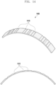
- FIG. 5 is a view illustrating a non-bent battery cell.
- FIG.5 illustrates a battery-cell in an initial flat, generally planar, un-bent, straight, or uncurved configuration, with the layers wound around a flat winding plane.
- FIG. 6 is a view illustrating a bent battery cell.
- the battery cell 301 may include a curved surface.
- a curved surface For example, at least a portion of a stack surface for the first electrode plate 341 (e.g., a positive electrode plate, a positive electrode layer, or a positive electrode film), the second electrode plate 342 (e.g., a negative electrode plate, a negative electrode layer, or a negative electrode film), and the separator 343 (e.g., a separation plate or a separation layer) may have the shape of a curved surface.
- the first electrode plate 341 e.g., a positive electrode plate, a positive electrode layer, or a positive electrode film
- the second electrode plate 342 e.g., a negative electrode plate, a negative electrode layer, or a negative electrode film
- the separator 343 e.g., a separation plate or a separation layer
- the curve of the battery cell 301 may have a curvature radius R from 50 mm to 500 mm.
- the curvature radius R of the curve of the battery cell 301 may be 50 mm or less to match the shape of an electronic device (e.g., the electronic device 210 or 220 of FIG. 2 ) to which the curved battery 300 is applied.
- the curvature radius R of the curve of the battery cell 301 may be 500 mm or more to match the shape of an electronic device (e.g., the electronic device 210 or 220 of FIG. 2 ) to which the curved battery 300 is applied.
- the bent battery cell 301 may have the characteristic of being restored (e.g., unfolded) to its original plate shape over time by the restoring force of the first electrode plate 341 (e.g., a positive electrode plate, a positive electrode layer, or a positive electrode film), the second electrode plate 342 (e.g., a negative electrode plate, a negative electrode layer, or a negative electrode film), and the separator 343 (e.g., a separation plate or a separation layer).
- the resilience of one or more of these layers may urge the curved structure to straighten or flatten, at least partially.
- At least one of the first electrode tab 320 e.g., a first electrode lead, a positive electrode tab, or a positive electrode lead
- the second electrode tab 330 e.g., a second electrode lead, a negative electrode tab, or a negative electrode lead
- the first electrode tab 320 e.g., a first electrode lead, a positive electrode tab, or a positive electrode lead
- the second electrode tab 330 e.g., a second electrode lead, a negative electrode tab, or a negative electrode lead
- At least one of the first and second electrode tabs may be arranged to extend along a length of the battery cell, and/or to have a length equal to, or greater than, a length of the battery cell in a direction generally perpendicular to the winding axis or winding plane.
- the second electrode tab 330 may include not only a portion that overlaps the second electrode plate 342 (e.g., a negative electrode plate, a negative electrode layer, or a negative electrode film), but also a portion that is disposed outside the housing 310 (e.g., the portion 332 of the second electrode tab 330 in FIG. 3 that is disposed outside the housing 310).
- the first electrode tab 320 (e.g., a first electrode lead, a positive electrode tab, or a positive electrode lead) may be electrically bonded (e.g., welded) to at least a portion of the first electrode plate 341 (e.g., a positive electrode plate, a positive electrode layer, or a positive electrode film).
- the first electrode tab 320 (e.g., a first electrode lead, a positive electrode tab, or a positive electrode lead) may be arranged on the uppermost surface of the first electrode plate 341 (e.g., a positive electrode plate, a positive electrode layer, or a positive electrode film) to correspond to the length of the battery cell 301.
- the first electrode tab 320 (e.g., a first electrode lead, a positive electrode tab, or a positive electrode lead) may be arranged above or below the uppermost surface of the first electrode plate 341 (e.g., a positive electrode plate, a positive electrode layer, or a positive electrode film).
- the first electrode tab 320 (e.g., a first electrode lead, a positive electrode tab, or a positive electrode lead) may be arranged on the lowermost surface of the first electrode plate 341 (e.g., a positive electrode plate, a positive electrode layer, or a positive electrode film) to correspond to the length of the battery cell 301.
- the first electrode tab 320 (e.g., a first electrode lead, a positive electrode tab, or a positive electrode lead) may be arranged above or below the lowermost surface of the first electrode plate 341 (e.g., a positive electrode plate, a positive electrode layer, or a positive electrode film).
- a portion of the first electrode tab 320 may be disposed to overlap the first electrode plate 341, and the portion 322 that does not overlap the first electrode plate 341 may be disposed to be exposed outside the housing 310.
- the first electrode tab 320 may be electrically bonded (e.g., welded) at one or more points (e.g., multiple points 325) in the area where it is disposed to overlap the first electrode plate 341.
- the first electrode tab 320 (e.g., a first electrode lead, a positive electrode tab, or a positive electrode lead) may be electrically bonded (e.g., welded) to the lowermost surface of the first electrode plate 341 (e.g., a positive electrode plate, a positive electrode layer, or a positive electrode film).
- the second electrode tab 330 (e.g., a second electrode lead, a negative electrode tab, or a negative electrode lead) may be electrically bonded (e.g., welded) to at least a portion of the second electrode plate 342 (e.g., a negative electrode plate, a negative electrode layer, or a negative electrode film).
- the second electrode tab 330 (e.g., a second electrode lead, a negative electrode tab, or a negative electrode lead) may be arranged on the uppermost surface of the second electrode plate 342 (e.g., a negative electrode plate, a negative electrode layer, or a negative electrode film) on one side portion of the battery cell 301.
- the second electrode plate 342 e.g., a negative electrode plate, a negative electrode layer, or a negative electrode film
- a portion of the second electrode tab 330 may be disposed to overlap the second electrode plate 342, and the portion 332 that does not overlap the second electrode plate 342 may be disposed to be exposed outside the housing 310.
- the second electrode tab 330 may be electrically bonded (e.g., welded) at one or more points (e.g., on a side portion 305) in the area where it is disposed to overlap the second electrode plate 342.
- the second electrode tab 330 (e.g., a second electrode lead, a negative electrode tab, or a negative electrode lead) may be electrically bonded (e.g., welded) to the lowermost surface of the second electrode plate 342 (e.g., a negative electrode plate, a negative electrode layer, or a negative electrode film).
- the first electrode tab 320 (e.g., a first electrode lead, a positive electrode tab, or a positive electrode lead) is arranged to correspond to the uppermost surface (or the lowermost surface) of the first electrode plate 341 (e.g., a positive electrode plate, a positive electrode layer, or a positive electrode film) from the first side 3411 to the second side 3412, the first electrode tab 320 (e.g., a first electrode lead, a positive electrode tab, or a positive electrode lead) is capable of supporting the battery cell 301.
- the first electrode tab 320 e.g., a first electrode lead, a positive electrode tab, or a positive electrode lead
- the first electrode tab 320 (e.g., a first electrode lead, a positive electrode tab, or a positive electrode lead) is capable of preventing the bent battery cell 301 from being restored (e.g., unfolded) to its original shape so that the bent shape can be maintained.
- the first electrode tab 320 (e.g., a first electrode lead, a positive electrode tab, or a positive electrode lead) supports the battery cell 301, but the disclosure is not limited thereto.
- the second electrode tab 330 (e.g., a second electrode lead, a negative electrode tab, or a negative electrode lead) may extend in length to support the battery cell 301.
- FIG. 7 is a view illustrating a bent battery cell.
- the first electrode tab 320 e.g., a first electrode lead, a positive electrode tab, or a positive electrode lead
- the second electrode tab 330 e.g., a second electrode lead, a negative electrode tab, or a negative electrode lead
- the first electrode tab 320 may include not only a portion that overlaps the first electrode plate 341 (e.g., a positive electrode plate, a positive electrode layer, or a positive electrode film), but also a portion that is disposed outside the housing 310 (e.g., the portion 322 of the first electrode tab 320 in FIG. 3 that is disposed outside the housing 310).
- the first electrode tab 320 (e.g., a first electrode lead, a positive electrode tab, or a positive electrode lead) may be arranged on the lowermost surface of the first electrode plate 341 (e.g., a positive electrode plate, a positive electrode layer, or a positive electrode film) to correspond to the length of the battery cell 301.
- the first electrode tab 320 (e.g., a first electrode lead, a positive electrode tab, or a positive electrode lead) may be arranged above or below the lowermost surface of the first electrode plate 341 (e.g., a positive electrode plate, a positive electrode layer, or a positive electrode film).
- first electrode tab 320 may be disposed to overlap the first electrode plate 341, and the portion 322 that does not overlap the first electrode plate 341 may be disposed to be exposed outside the housing 310.
- the first electrode tab 320 may be electrically bonded (e.g., welded) at one or more points (e.g., multiple points 325) in the area where it is disposed to overlap the first electrode plate 341.
- the second electrode tab 330 may include not only a portion that overlaps the second electrode plate 342 (e.g., a negative electrode plate, a negative electrode layer, or a negative electrode film), but also a portion that is disposed outside the housing 310 (e.g., the portion 332 of the second electrode tab 330 in FIG. 3 that is disposed outside the housing 310).
- the first electrode tab 320 (e.g., a first electrode lead, a positive electrode tab, or a positive electrode lead) may be electrically bonded (e.g., welded) to at least a portion of the first electrode plate 341 (e.g., a positive electrode plate, a positive electrode layer, or a positive electrode film).
- the first electrode tab 320 (e.g., a first electrode lead, a positive electrode tab, or a positive electrode lead) may be arranged on the uppermost surface of the first electrode plate 341 (e.g., a positive electrode plate, a positive electrode layer, or a positive electrode film) to correspond to the length of the battery cell 701.
- the first electrode plate 341 e.g., a positive electrode plate, a positive electrode layer, or a positive electrode film
- the first electrode tab 320 (e.g., a first electrode lead, a positive electrode tab, or a positive electrode lead) may be arranged to correspond to the uppermost surface (or the lowermost surface) of the first electrode plate 341 (e.g., a positive electrode plate, a positive electrode layer, or a positive electrode film) from the first side 3411 to the second side 3412 of the uppermost surface (or the lowermost surface).
- the first electrode plate 341 e.g., a positive electrode plate, a positive electrode layer, or a positive electrode film
- the first electrode tab 320 (e.g., a first electrode lead, a positive electrode tab, or a positive electrode lead) is arranged to correspond to the uppermost surface (or the lowermost surface) of the first electrode plate 341 (e.g., a positive electrode plate, a positive electrode layer, or a positive electrode film) from the first side 3411 to the second side 3412 of the uppermost surface (or the lowermost surface), the first electrode tab 320 (e.g., a first electrode lead, a positive electrode tab, or a positive electrode lead) is capable of supporting the battery cell 701.
- the first electrode tab 320 e.g., a first electrode lead, a positive electrode tab, or a positive electrode lead
- the first electrode tab 320 (e.g., a first electrode lead, a positive electrode tab, or a positive electrode lead) is capable of preventing the bent battery cell 701 from being restored (e.g., unfolded) to its original shape so that the bent shape can be maintained.
- the second electrode tab 330 (e.g., a second electrode lead, a negative electrode tab, or a negative electrode lead) may be arranged on the lowermost surface of the second electrode plate 342 (e.g., a negative electrode plate, a negative electrode layer, or a negative electrode film) to correspond to the length of the battery cell 301.
- the second electrode tab 330 (e.g., a second electrode lead, a negative electrode tab, or a negative electrode lead) may be arranged above or below the lowermost surface of the second electrode plate 342 (e.g., a negative electrode plate, a negative electrode layer, or a negative electrode film).
- a portion of the second electrode tab 330 may be disposed to overlap the second electrode plate 342, and the portion 332 that does not overlap the second electrode plate 342 may be disposed to be exposed outside the housing 310.
- the second electrode tab 330 may be electrically bonded (e.g., welded) at one or more points (e.g., multiple points 335) in the area where it is disposed to overlap the second electrode plate 342.
- the second electrode tab 330 (e.g., a second electrode lead, a negative electrode tab, or a negative electrode lead) may be arranged on the uppermost surface of the second electrode plate 342 (e.g., a negative electrode plate, a negative electrode layer, or a negative electrode film) to correspond to the length of the battery cell 701.
- the second electrode plate 342 e.g., a negative electrode plate, a negative electrode layer, or a negative electrode film
- the second electrode tab 330 (e.g., a second electrode lead, a negative electrode tab, or a negative electrode lead) may be arranged to correspond to the uppermost surface (or the lowermost surface) of the second electrode plate 342 (e.g., a negative electrode plate, a negative electrode layer, or a negative electrode film) from the first side 3421 to the second side 3422 of the uppermost surface (or the lowermost surface).
- the second electrode plate 342 e.g., a negative electrode plate, a negative electrode layer, or a negative electrode film
- the second electrode tab 330 (e.g., a second electrode lead, a negative electrode tab, or a negative electrode lead) may be electrically bonded (e.g., welded) to the second electrode plate 342 (e.g., a positive electrode plate, a positive electrode layer, or a positive electrode film) at multiple points 335.
- the second electrode tab 330 (e.g., a second electrode lead, a negative electrode tab, or a negative electrode lead) may be electrically bonded (e.g., welded) to the uppermost surface of the second electrode plate 342 (e.g., a negative electrode plate, a negative electrode layer, or a negative electrode film).
- the battery cell 301 may include a curved surface.
- a curved surface For example, at least a portion of a stack surface for the first electrode plate 341 (e.g., a positive electrode plate, a positive electrode layer, or a positive electrode film), the second electrode plate 342 (e.g., a negative electrode plate, a negative electrode layer, or a negative electrode film), and the separator 343 (e.g., a separation plate or a separation layer) may have the shape of a curved surface.
- the first electrode plate 341 e.g., a positive electrode plate, a positive electrode layer, or a positive electrode film
- the second electrode plate 342 e.g., a negative electrode plate, a negative electrode layer, or a negative electrode film
- the separator 343 e.g., a separation plate or a separation layer
- the curve of the battery cell 301 may have a curvature radius R from 50 mm to 500 mm.
- the curvature radius R of the curve of the battery cell 301 may be 50 mm or less to match the shape of an electronic device (e.g., the electronic device 210 or 220 of FIG. 2 ) to which the curved battery 300 is applied.
- the curvature radius R of the curve of the battery cell 301 may be 500 mm or more to match the shape of an electronic device (e.g., the electronic device 210 or 220 of FIG. 2 ) to which the curved battery 300 is applied.
- the second electrode tab 330 (e.g., a second electrode lead, a negative electrode tab, or a negative electrode lead) is arranged to correspond to the uppermost surface (or the lowermost surface) of the second electrode plate 342 (e.g., a negative electrode plate, a negative electrode layer, or a negative electrode film) from the first side 3421 to the second side 3422 of the uppermost surface (or the lowermost surface), the second electrode tab 330 (e.g., a second electrode lead, a negative electrode tab, or a negative electrode lead) is capable of supporting the battery cell 701.
- the second electrode tab 330 e.g., a second electrode lead, a negative electrode tab, or a negative electrode lead
- the second electrode tab 330 (e.g., a second electrode lead, a negative electrode tab, or a negative electrode lead) is capable of preventing the bent battery cell 301 from being restored (e.g., unfolded) to its original shape so that the bent shape can be maintained.
- FIG. 8 is a view illustrating a bent battery cell.
- a curved battery (e.g., the curved battery 300 in FIGS. 3 and 4 ) according to an embodiment of the disclosure may include a battery cell 801 (e.g., a battery pouch) and a housing 310 (e.g., the housing 310 in FIGS. 3 and 4 ) (e.g., a case).
- a battery cell 801 e.g., a battery pouch
- a housing 310 e.g., the housing 310 in FIGS. 3 and 4
- a case e.g., a case
- the housing 310 may include an inner space having the curved surface shapes (e.g., G1 and G2 in FIG. 4 ) corresponding to the shapes of surfaces (e.g., S1 and S2 in FIG. 4 ) (e.g., curved surface shapes) of the battery cell 801 (e.g., a battery pouch).
- the battery cell 801 may be disposed in the inner space of the housing 310, and the battery cell 801 may be sealed by the housing 310.
- the surface of the battery cell 801 may include a concave first surface S1 (e.g., the first surface S1 in FIG. 4 ) and a convex second surface S2 (e.g., the second surface S2 in FIG. 4 ).
- the concave first surface S1 may be the bottom surface of the battery cell 801
- the convex second surface S2 may be the top surface of the battery cell 801.
- the concave first surface S1 may be the top surface of the battery cell 801
- the convex second surface S2 may be the bottom surface of the battery cell 801.
- the battery cell 801 may include a first electrode plate 841 (e.g., a positive electrode plate, a positive electrode layer, a positive electrode film), a second electrode plate 842 (e.g., the second electrode plate 342 in FIG. 4 ) (e.g., a negative electrode plate, a negative electrode layer, or a negative electrode film), a separator 343 (e.g., the separator 343 in FIG. 4 ) (e.g.
- first electrode tab 820 e.g., a first electrode lead, a positive electrode tab, or a positive electrode lead
- second electrode tab 830 e.g., a second electrode lead, a negative electrode tab, or a negative electrode lead
- the first electrode tab 820 (e.g., a first electrode lead, a positive electrode tab, or a positive electrode lead) may include not only a portion that overlaps the first electrode plate 841 (e.g., a positive electrode plate, a positive electrode layer, or a positive electrode film), but also a portion that is disposed outside the housing 310 (e.g., the portion 322 of the first electrode tab 320 in FIG. 3 that is disposed outside the housing 310).
- the second electrode tab 830 may include not only a portion that overlaps the second electrode plate 842 (e.g., a negative electrode plate, a negative electrode layer, or a negative electrode film), but also a portion that is disposed outside the housing 310 (e.g., the portion 332 of the second electrode tab 330 in FIG. 3 that is disposed outside the housing 310).
- the first electrode tab 820 e.g., a first electrode lead, a positive electrode tab, or a positive electrode lead
- the second electrode tab 830 e.g., a second electrode lead, a negative electrode tab, or a negative electrode lead
- the separator (e.g., the separator 343 in FIG. 4 ) (e.g., a separation plate or a separation layer) may be disposed between the first electrode plate 841 (e.g., a positive electrode plate, a positive electrode layer, or a positive electrode film) and the second electrode plate 842 (e.g., a negative electrode plate, a negative electrode layer, or a negative electrode film) to electrically separate the first electrode plate 841 (e.g., a positive electrode plate, a positive electrode layer, or a positive electrode film) and the second electrode plate 842 (e.g., a negative electrode plate, a negative electrode layer, or a negative electrode film).
- the first electrode plate 841 e.g., a positive electrode plate, a positive electrode layer, or a positive electrode film
- the second electrode plate 842 e.g., a negative electrode plate, a negative electrode layer, or a negative electrode film
- the first electrode plate 841 e.g., a positive electrode plate, a positive electrode layer, or a positive electrode film
- the second electrode plate 842 e.g., a negative electrode plate, a negative electrode layer, or a negative electrode film
- the first electrode plate 841 e.g., a positive electrode plate, a positive electrode layer, or a positive electrode film
- the second electrode plate 842 e.g., a negative electrode plate, a negative electrode layer, or a negative electrode film
- the battery cell 801 may be wound in the form of a jelly-roll after sequentially stacking the first electrode plate 841 (e.g., a positive electrode plate, a positive electrode layer, or a positive electrode film), the separator (e.g., the separator 343 in FIG. 4 ) (e.g., a separation plate or a separation layer), and the second electrode plate 842 (e.g., a negative electrode plate, a negative electrode layer, or a negative electrode film).
- the first electrode plate 841 e.g., a positive electrode plate, a positive electrode layer, or a positive electrode film
- the separator e.g., the separator 343 in FIG. 4
- the second electrode plate 842 e.g., a negative electrode plate, a negative electrode layer, or a negative electrode film.
- the battery cell 801 may be formed by sequentially and repeatedly stacking the first electrode plate 841 (e.g., a positive electrode plate, a positive electrode layer, or a positive electrode film), the separator (e.g., the separator 343 in FIG. 4 ) (e.g., a separation plate or a separation layer), and the second electrode plate 842 (e.g., a negative electrode plate, a negative electrode layer, or a negative electrode film).
- the first electrode plate 841 e.g., a positive electrode plate, a positive electrode layer, or a positive electrode film
- the separator e.g., the separator 343 in FIG. 4
- the second electrode plate 842 e.g., a negative electrode plate, a negative electrode layer, or a negative electrode film.
- the separator e.g., the separator 343 in FIG. 4
- the separator 343 in FIG. 4 may be formed by forming a non-conductive porous layer on the first electrode plate 841 (e.g., a positive electrode plate, a positive electrode layer, or a positive electrode film) or the second electrode plate 842 (e.g., a negative electrode plate, a negative electrode layer, or a negative electrode film).
- the separator e.g., the separator 343) (e.g., a separation plate or a separation layer) may be provided to electrically separate the first electrode plate 841 (e.g., a positive electrode plate, a positive electrode layer, or a positive electrode film) and the second electrode plate 112.
- the separator e.g., the separator 343 (e.g., a separation plate or a separation layer) may be provided to electrically separate the first electrode plate 841 (e.g., a positive electrode plate, a positive electrode layer, or a positive electrode film) and the second electrode plate 112.
- the first electrode tab 820 e.g., a first electrode lead, a positive electrode tab, or a positive electrode lead
- the second electrode tab 830 e.g., a second electrode lead, a negative electrode tab, or a negative electrode lead
- the first electrode tab 820 e.g., a first electrode lead, a positive electrode tab, or a positive electrode lead
- the second electrode tab 830 e.g., a second electrode lead, a negative electrode tab, or a negative electrode lead
- the first electrode tab 820 e.g., a first electrode lead, a positive electrode tab, or a positive electrode lead
- the second electrode tab 830 e.g., a second electrode lead, a negative electrode tab, or a negative electrode lead
- the first electrode tab 820 e.g., a first electrode lead, a positive electrode tab, or a positive electrode lead
- the portion 322 of the first electrode tab 320 in FIG. 3 that is exposed outside the housing 310 may be exposed outside the housing 310 such that the battery cell 801 can be electrically connected to external electronic components.
- At least a portion of the second electrode tab 830 e.g., the portion 332 of the second electrode tab 330 of FIG. 3 that is disposed outside the housing 310) may be exposed outside the housing 310.
- the first electrode tab 820 (e.g., a first electrode lead, a positive electrode tab, or a positive electrode lead) may be arranged above or below the uppermost surface of the first electrode plate 841 (e.g., a positive electrode plate, a positive electrode layer, or a positive electrode film).
- the first electrode tab 820 (e.g., a first electrode lead, a positive electrode tab, or a positive electrode lead) may be arranged above or below the lowermost surface of the first electrode plate 841 (e.g., a positive electrode plate, a positive electrode layer, or a positive electrode film).
- the first electrode tab 820 (e.g., a first electrode lead, a positive electrode tab, or a positive electrode lead) may be electrically connected to the first electrode plate 841 (e.g., a positive electrode plate, a positive electrode layer, or a positive electrode film).
- the first electrode tab 820 (e.g., a first electrode lead, a positive electrode tab, or a positive electrode lead) may be electrically bonded (e.g., joined) to the first uncoated portion of the first electrode plate 841 (e.g., a positive electrode plate, a positive electrode layer, or a positive electrode film) by welding.
- the second electrode tab 830 (e.g., a second electrode lead, a negative electrode tab, or a negative electrode lead) may be arranged above or below the lowermost surface of the second electrode plate 842 (e.g., a negative electrode plate, a negative electrode layer, or a negative electrode film).
- the second electrode tab 830 (e.g., a second electrode lead, a negative electrode tab, or a negative electrode lead) may be electrically connected to the second electrode plate 842 (e.g., a negative electrode plate, a negative electrode layer, or a negative electrode film).
- the second electrode tab 830 (e.g., a second electrode lead, a negative electrode tab, or a negative electrode lead) may be electrically bonded (e.g., joined) to the second uncoated portion of the second electrode plate 842 (e.g., a negative electrode plate, a negative electrode layer, or a negative electrode film) by welding.
- a non-bent battery cell (e.g., the battery cell 301 in FIG. 5 ) may be placed on a mold (e.g., a jig) having a predetermined sloped surface (or a predetermined shape), and then the battery cell 801 may be pressed to form a bent battery cell (e.g., the battery cell 801 in FIG. 8 ).
- a mold e.g., a jig
- the battery cell 801 may include a sloped surface.
- a stack surface for the first electrode plate 841 e.g., a positive electrode plate, a positive electrode layer, or a positive electrode film
- the second electrode plate 842 e.g., a negative electrode plate, a negative electrode layer, or a negative electrode film
- the separator e.g., the separator 343
- a separation plate or a separation layer may have a sloped surface shape.
- multiple portions may be bent by predetermined angles 840 and 850 to form multiple sloped surfaces 851.
- the bent battery cell 801 may have the characteristic of being restored (e.g., unfolded) to its original plate shape over time by the restoring force of the first electrode plate 841 (e.g., a positive electrode plate, a positive electrode layer, or a positive electrode film), the second electrode plate 842 (e.g., a negative electrode plate, a negative electrode layer, or a negative electrode film), and the separator (e.g., the separator 343 in FIG. 4 ) (e.g., a separation plate or a separation layer).
- the first electrode plate 841 e.g., a positive electrode plate, a positive electrode layer, or a positive electrode film
- the second electrode plate 842 e.g., a negative electrode plate, a negative electrode layer, or a negative electrode film
- the separator e.g., the separator 343 in FIG. 4
- At least one of the first electrode tab 820 e.g., a first electrode lead, a positive electrode tab, or a positive electrode lead
- the second electrode tab 830 e.g., a second electrode lead, a negative electrode tab, or a negative electrode lead
- the first electrode tab 820 e.g., a first electrode lead, a positive electrode tab, or a positive electrode lead
- the second electrode tab 830 e.g., a second electrode lead, a negative electrode tab, or a negative electrode lead
- the first electrode tab 820 (e.g., a first electrode lead, a positive electrode tab, or a positive electrode lead) may be electrically bonded (e.g., welded) to at least a portion of the first electrode plate 841 (e.g., a positive electrode plate, a positive electrode layer, or a positive electrode film).
- the first electrode tab 820 (e.g., a first electrode lead, a positive electrode tab, or a positive electrode lead) may be arranged on the uppermost surface of the first electrode plate 841 (e.g., a positive electrode plate, a positive electrode layer, or a positive electrode film) to correspond to the length of the battery cell 801.
- the first electrode tab 820 (e.g., a first electrode lead, a positive electrode tab, or a positive electrode lead) may be arranged on the lowermost surface of the first electrode plate 841 (e.g., a positive electrode plate, a positive electrode layer, or a positive electrode film) to correspond to the length of the battery cell 801.
- the first electrode tab 820 (e.g., a first electrode lead, a positive electrode tab, or a positive electrode lead) may be arranged to correspond to the uppermost surface (or the lowermost surface) of the first electrode plate 841 (e.g., a positive electrode plate, a positive electrode layer, or a positive electrode film) from the first side 8411 to the second side 8412 of the uppermost surface (or the lowermost surface).
- the first electrode plate 841 e.g., a positive electrode plate, a positive electrode layer, or a positive electrode film
- the first electrode tab 820 (e.g., a first electrode lead, a positive electrode tab, or a positive electrode lead) may be electrically bonded (e.g., welded) to the first electrode plate 841 (e.g., a positive electrode plate, a positive electrode layer, or a positive electrode film) at multiple points 825.
- the first electrode tab 820 (e.g., a first electrode lead, a positive electrode tab, or a positive electrode lead) may be electrically bonded (e.g., welded) to the uppermost surface of the first electrode plate 841 (e.g., a positive electrode plate, a positive electrode layer, or a positive electrode film).
- the first electrode tab 820 (e.g., a first electrode lead, a positive electrode tab, or a positive electrode lead) may be electrically bonded (e.g., welded) to the lowermost surface of the first electrode plate 841 (e.g., a positive electrode plate, a positive electrode layer, or a positive electrode film).
- the second electrode tab 830 (e.g., a second electrode lead, a negative electrode tab, or a negative electrode lead) may be electrically bonded (e.g., welded) to at least a portion of the second electrode plate 842 (e.g., a negative electrode plate, a negative electrode layer, or a negative electrode film).
- the second electrode tab 830 (e.g., a second electrode lead, a negative electrode tab, or a negative electrode lead) may be arranged on the uppermost surface of the second electrode plate 842 (e.g., a negative electrode plate, a negative electrode layer, or a negative electrode film) at one side portion of the battery cell 801.
- the second electrode tab 830 (e.g., a second electrode lead, a negative electrode tab, or a negative electrode lead) may be arranged on the lowermost surface of the second electrode plate 842 (e.g., a negative electrode plate, a negative electrode layer, or a negative electrode film) in one side portion of the battery cell 801.
- the second electrode tab 830 (e.g., a second electrode lead, a negative electrode tab, or a negative electrode lead) may be electrically bonded (e.g., welded) to the second electrode plate 842 (e.g., a negative electrode plate, a negative electrode layer, or a negative electrode film) in one side portion 805 of the battery cell 801.
- the second electrode tab 830 (e.g., a second electrode lead, a negative electrode tab, or a negative electrode lead) may be electrically bonded (e.g., welded) to the uppermost surface of the second electrode plate 842 (e.g., a negative electrode plate, a negative electrode layer, or a negative electrode film).
- the second electrode tab 830 (e.g., a second electrode lead, a negative electrode tab, or a negative electrode lead) may be electrically bonded (e.g., welded) to the lowermost surface of the second electrode plate 842 (e.g., a negative electrode plate, a negative electrode layer, or a negative electrode film).
- the first electrode tab 820 (e.g., a first electrode lead, a positive electrode tab, or a positive electrode lead) is arranged to correspond to the uppermost surface (or the lowermost surface) of the first electrode plate 841 (e.g., a positive electrode plate, a positive electrode layer, or a positive electrode film) from the first side 8411 to the second side 8412, the first electrode tab 820 (e.g., a first electrode lead, a positive electrode tab, or a positive electrode lead) is capable of supporting the battery cell 801.
- the first electrode tab 820 e.g., a first electrode lead, a positive electrode tab, or a positive electrode lead
- the first electrode tab 820 (e.g., a first electrode lead, a positive electrode tab, or a positive electrode lead) is capable of preventing the bent battery cell 801 from being restored (e.g., unfolded) to its original shape so that the bent shape can be maintained.
- the first electrode tab 820 (e.g., a first electrode lead, a positive electrode tab, or a positive electrode lead) supports the battery cell 801, but the disclosure is not limited thereto.
- the second electrode tab 830 (e.g., a second electrode lead, a negative electrode tab, or a negative electrode lead) may extend in length to support the battery cell 801.
- FIG. 9 is a view illustrating a bent battery cell.
- the battery cell 801 may include a sloped surface.
- a stack surface for the first electrode plate 841 e.g., a positive electrode plate, a positive electrode layer, or a positive electrode film
- the second electrode plate 842 e.g., a negative electrode plate, a negative electrode layer, or a negative electrode film
- the separator e.g., the separator 343 in FIG. 4
- a separation plate or a separation layer may have a sloped surface shape.
- multiple portions may be bent by predetermined angles 840 and 850 to form multiple sloped surfaces 851.
- the first electrode tab 820 e.g., a first electrode lead, a positive electrode tab, or a positive electrode lead
- the second electrode tab 830 e.g., a second electrode lead, a negative electrode tab, or a negative electrode lead
- the first electrode tab 820 (e.g., a first electrode lead, a positive electrode tab, or a positive electrode lead) may include not only a portion that overlaps the first electrode plate 841 (e.g., a positive electrode plate, a positive electrode layer, or a positive electrode film), but also a portion that is disposed outside the housing 310 (e.g., the portion 322 of the first electrode tab 320 in FIG. 3 that is disposed outside).
- the second electrode tab 830 may include not only a portion that overlaps the second electrode plate 842 (e.g., a negative electrode plate, a negative electrode layer, or a negative electrode film), but also a portion that is disposed outside the housing (e.g., the housing 310 in FIG. 4 ) (e.g., the portion 332 of the second electrode tab 330 in FIG. 3 that is disposed outside).
- the first electrode tab 820 (e.g., a first electrode lead, a positive electrode tab, or a positive electrode lead) may be electrically bonded (e.g., welded) to at least a portion of the first electrode plate 841 (e.g., a positive electrode plate, a positive electrode layer, or a positive electrode film).
- the first electrode tab 820 (e.g., a first electrode lead, a positive electrode tab, or a positive electrode lead) may be arranged on the uppermost surface of the first electrode plate 841 (e.g., a positive electrode plate, a positive electrode layer, or a positive electrode film) to correspond to the length of the battery cell 901.
- the first electrode tab 820 (e.g., a first electrode lead, a positive electrode tab, or a positive electrode lead) may be arranged on the lowermost surface of the first electrode plate 841 (e.g., a positive electrode plate, a positive electrode layer, or a positive electrode film) to correspond to the length of the battery cell 901.
- the first electrode tab 820 (e.g., a first electrode lead, a positive electrode tab, or a positive electrode lead) may be arranged to correspond to the uppermost surface (or the lowermost surface) of the first electrode plate 841 (e.g., a positive electrode plate, a positive electrode layer, or a positive electrode film) from the first side 8411 to the second side 8412 of the uppermost surface (or the lowermost surface).
- the first electrode plate 841 e.g., a positive electrode plate, a positive electrode layer, or a positive electrode film
- the first electrode tab 820 (e.g., a first electrode lead, a positive electrode tab, or a positive electrode lead) may be electrically bonded (e.g., welded) to the first electrode plate 841 (e.g., a positive electrode plate, a positive electrode layer, or a positive electrode film) at multiple points 825.
- the first electrode tab 820 (e.g., a first electrode lead, a positive electrode tab, or a positive electrode lead) may be electrically bonded (e.g., welded) to the uppermost surface of the first electrode plate 841 (e.g., a positive electrode plate, a positive electrode layer, or a positive electrode film).
- the first electrode tab 820 (e.g., a first electrode lead, a positive electrode tab, or a positive electrode lead) may be electrically bonded (e.g., welded) to the lowermost surface of the first electrode plate 841 (e.g., a positive electrode plate, a positive electrode layer, or a positive electrode film).
- the first electrode tab 820 (e.g., a first electrode lead, a positive electrode tab, or a positive electrode lead) is arranged to correspond to the uppermost surface (or the lowermost surface) of the first electrode plate 841 (e.g., a positive electrode plate, a positive electrode layer, or a positive electrode film) from the first side 8411 to the second side 8412, the first electrode tab 820 (e.g., a first electrode lead, a positive electrode tab, or a positive electrode lead) is capable of supporting the battery cell 901.
- the first electrode tab 820 e.g., a first electrode lead, a positive electrode tab, or a positive electrode lead
- the first electrode tab 820 (e.g., a first electrode lead, a positive electrode tab, or a positive electrode lead) is capable of preventing the bent battery cell 901 from being restored (e.g., unfolded) to its original shape so that the bent shape can be maintained.
- the second electrode tab 830 (e.g., a second electrode lead, a negative electrode tab, or a negative electrode lead) may be electrically bonded (e.g., welded) to at least a portion of the second electrode plate 842 (e.g., a negative electrode plate, a negative electrode layer, or a negative electrode film).
- the second electrode tab 830 (e.g., a second electrode lead, a negative electrode tab, or a negative electrode lead) may be arranged on the uppermost surface of the second electrode plate 842 (e.g., a negative electrode plate, a negative electrode layer, or a negative electrode film) to correspond to the length of the battery cell 901.
- the second electrode tab 830 (e.g., a second electrode lead, a negative electrode tab, or a negative electrode lead) may be arranged on the lowermost surface of the second electrode plate 842 (e.g., a negative electrode plate, a negative electrode layer, or a negative electrode film) to correspond to the length of the battery cell 901.
- the second electrode tab 830 (e.g., a second electrode lead, a negative electrode tab, or a negative electrode lead) may be arranged to correspond to the uppermost surface (or the lowermost surface) of the second electrode plate 842 (e.g., a negative electrode plate, a negative electrode layer, or a negative electrode film) from the first side 8421 to the second side 8422 of the uppermost surface (or the lowermost surface).
- the second electrode plate 842 e.g., a negative electrode plate, a negative electrode layer, or a negative electrode film
- the second electrode tab 830 (e.g., a second electrode lead, a negative electrode tab, or a negative electrode lead) may be electrically bonded (e.g., welded) to the second electrode plate 842 (e.g., a positive electrode plate, a positive electrode layer, or a positive electrode film) at multiple points 835.
- the second electrode tab 830 (e.g., a second electrode lead, a negative electrode tab, or a negative electrode lead) may be electrically bonded (e.g., welded) to the uppermost surface of the second electrode plate 842 (e.g., a negative electrode plate, a negative electrode layer, or a negative electrode film).
- the second electrode tab 830 (e.g., a second electrode lead, a negative electrode tab, or a negative electrode lead) is arranged to correspond to the uppermost surface (or the lowermost surface) of the second electrode plate 842 (e.g., a negative electrode plate, a negative electrode layer, or a negative electrode film) from the first side 8421 to the second side 8422 of the uppermost surface (or the lowermost surface), the second electrode tab 830 (e.g., a second electrode lead, a negative electrode tab, or a negative electrode lead) is capable of supporting the battery cell 901.
- the second electrode tab 830 e.g., a second electrode lead, a negative electrode tab, or a negative electrode lead
- the second electrode tab 830 (e.g., a second electrode lead, a negative electrode tab, or a negative electrode lead) is capable of preventing the bent battery cell 901 from being restored (e.g., unfolded) to its original shape so that the bent shape can be maintained.
- FIG. 10 is a view illustrating the shape of an electrode tab of a curved battery according to an embodiment of the disclosure.
- electrode tabs 1000 e.g., the first electrode tab 320 and the second electrode tab 320 in FIGS. 6 and 7 and the first electrode tab 820 and the second electrode tab 830 in FIGS. 8 and 9
- a curved battery e.g., the curved battery 300 in FIGS. 3 and 4
- electrode tabs 1000 may be formed in a bar type extending in the longitudinal direction of a battery cell (e.g., the battery cell 301 in FIG. 6 , the battery cell 701 in FIG. 7 , the battery cell 801 in FIG. 8 , or the battery cell 901 in FIG. 9 ).
- the electrode tabs 1000 of the curved battery may be formed in a bar type including a lattice pattern.
- FIG. 11 is a view illustrating the shape of an electrode tab of a curved battery according to an embodiment of the disclosure.
- electrode tabs 1100 (e.g., the first electrode tab 320 and the second electrode tab 320 in FIGS. 6 and 7 and the first electrode tab 820 and the second electrode tab 830 in FIGS. 8 and 9 ) of a curved battery (e.g., the curved battery 300 in FIGS. 3 and 4 ) according to an embodiment of the disclosure may be formed in a bar type extending in the longitudinal direction of a battery cell (e.g., the battery cell 301 in FIG. 6 , the battery cell 701 in FIG. 7 , the battery cell 801 in FIG. 8 , or the battery cell 901 in FIG. 9 ).
- a battery cell e.g., the battery cell 301 in FIG. 6 , the battery cell 701 in FIG. 7 , the battery cell 801 in FIG. 8 , or the battery cell 901 in FIG. 9 ).
- the electrode tabs may include multiple holes 1110 and/or notches 1120. At each of a plurality of positions (in this example, those positions are evenly spaced apart) along a length of the electrode tab there is provided a respective hole 1110 through the tab and a respective pair of notches 1120 in the sides of the tab, each notch 1120 extending in towards the respective hole 1110.
- the notches and holes reduce the cross sectional area of the tab material at each of the plurality of positions.
- the electrode tabs 1100 may include multiples holes 1110 arranged at predetermined intervals.
- the holes 1110 may be formed to penetrate the electrode tabs 1100 through the top and bottom surfaces.
- the electrode tabs 1100 may include multiples notches 1120 arranged at predetermined intervals.
- the multiple notches 1120 may be formed by removing portions of side surfaces of the electrode tabs 1100.
- multiple notches 1120 may be formed to correspond to the multiple holes 1110.
- FIG. 12 is a view illustrating the shape of an electrode tab of a curved battery according to an embodiment of the disclosure.
- electrode tabs 1200 (e.g., the first electrode tab 320 and the second electrode tab 320 in FIGS. 6 and 7 and the first electrode tab 820 and the second electrode tab 830 in FIGS. 8 and 9 ) of a curved battery (e.g., the curved battery 300 in FIGS. 3 and 4 ) according to an embodiment of the disclosure may be formed in a bar type extending in the longitudinal direction of a battery cell (e.g., the battery 301 cell in FIG. 6 , the battery cell 701 in FIG. 7 , the battery cell 801 in FIG. 8 , or the battery cell 901 in FIG. 9 ).
- a battery cell e.g., the battery 301 cell in FIG. 6 , the battery cell 701 in FIG. 7 , the battery cell 801 in FIG. 8 , or the battery cell 901 in FIG. 9 ).
- the electrode tabs may include multiple grooves 1220.
- each groove extends completely across a width of the electrode tab, but other embodiments may comprise grooves extending partially across the width of the electrode tab.
- Each groove reduces the cross sectional area of the electrode tab at its respective position. In this example, this reduction in cross-sectional area may be performed pre-bending. Then, when bending is performed, the stress at each position corresponding to a groove is greater than at positions longitudinally between the grooves, and can result in greater strain of the electrode tab material.
- the amount of bending (or the bending force) together with the material of the electrode tab may be arranged such that the strain of the tab material at the grove positions exceeds the tab material's elastic limit, becomes inelastic, and work-hardens the tab material at the locations of the grooves.
- This work hardening may result in the electrode tab retaining, at least partially, its bent shape after the bending force is removed, and thus the bent tab may also support the battery cell in its corresponding bent shape, against the action of any resilience of the battery-cell's other components.
- multiple grooves 1220 may be provided on the bottom surfaces of the electrode tabs 1200 at predetermined intervals.
- multiple grooves 1220 may be provided on the top surfaces of the electrode tabs 1200 at predetermined intervals.
- the multiple grooves 1220 may be arranged to correspond to portions 1210 where the electrode tabs 1200 are bent.
- the electrode tabs 1200 may further include multiple notches (e.g., the notches 1120 in FIG. 11 ) arranged at predetermined intervals.
- the multiple notches 1120 may be formed by removing portions of side surfaces of the electrode tabs 1100.
- FIG. 13 is a view illustrating the shape of an electrode tab of a curved battery according to an embodiment of the disclosure.
- electrode tabs 1300 (e.g., the first electrode tab 320 and the second electrode tab 320 in FIGS. 6 and 7 and the first electrode tab 820 and the second electrode tab 830 in FIGS. 8 and 9 ) of a curved battery (e.g., the curved battery 300 in FIGS. 3 and 4 ) according to an embodiment of the disclosure may be formed in a bar type extending in the longitudinal direction of a battery cell (e.g., the battery cell 301 in FIG. 6 , the battery cell 701 in FIG. 7 , the battery cell 801 in FIG. 8 , or the battery cell 901 in FIG. 9 ).
- a battery cell e.g., the battery cell 301 in FIG. 6 , the battery cell 701 in FIG. 7 , the battery cell 801 in FIG. 8 , or the battery cell 901 in FIG. 9 ).
- the electrode tabs 1300 may include multiple notches 1330.
- multiple notches 1330 may be provided on the bottom surfaces of the electrode tabs 1300 at predetermined intervals.
- multiple notches 1330 may be provided on the top surfaces of the electrode tabs 1300 at predetermined intervals.
- the multiple notches 1330 may be arranged to correspond to portions 1310 and 1320 where the electrode tabs 1300 are bent.
- FIG. 14 is a view illustrating the shape of an electrode tab of a curved battery according to an embodiment of the disclosure.
- electrode tabs 1400 (e.g., the first electrode tab 320 and the second electrode tab 320 in FIGS. 6 and 7 and the first electrode tab 820 and the second electrode tab 830 in FIGS. 8 and 9 ) of a curved battery (e.g., the curved battery 300 in FIGS. 3 and 4 ) according to an embodiment of the disclosure may be formed in a bar type extending in the longitudinal direction of a battery cell (e.g., the battery cell 301 in FIG. 6 , the battery cell 701 in FIG. 7 , the battery cell 801 in FIG. 8 , or the battery cell 901 in FIG. 9 ).
- a battery cell e.g., the battery cell 301 in FIG. 6 , the battery cell 701 in FIG. 7 , the battery cell 801 in FIG. 8 , or the battery cell 901 in FIG. 9 ).
- the electrode tabs 1400 may include multiple grooves 1410.
- multiple grooves 1410 may be provided on the top surfaces of the electrode tabs 1400 at predetermined intervals.
- multiple grooves 1410 may be provided on the bottom surfaces of the electrode tabs 1400 at predetermined intervals.
- the multiple grooves 1410 may be arranged to correspond to portions 1210 where the electrode tabs 1400 are bent.
- the plurality of grooves 1410 may be provided at equal intervals.
- the intervals of the multiple grooves 1410 may be different.
- the areas of the multiple grooves 1410 may be equal to each other.
- the areas of the multiple grooves 1410 may be different from each other.
- the electrode tabs 1400 may further include multiple notches (e.g., the notches 1120 in FIG. 11 ) arranged at predetermined intervals.
- the multiple notches 1120 may be formed by removing portions of side surfaces of the electrode tabs 1400.
- a curved battery (e.g., the curved battery 300 in FIGS. 3 and 4 ) according to an embodiment of the disclosure may include a battery cell (e.g., the battery cell 301 in FIG. 6 or the battery cell 701 in FIG. 7 ) having a curved cross section, and a housing (e.g., the housing 310 in FIGS. 3 and 4 ) disposed outside the battery cell 301 or 701.
- a battery cell e.g., the battery cell 301 in FIG. 6 or the battery cell 701 in FIG. 7
- a housing e.g., the housing 310 in FIGS. 3 and 4
- the battery cell 301 or 701 may include a positive electrode plate (e.g., the positive electrode plate 341 in FIG. 4 ), a negative electrode plate (e.g., the negative electrode plate 342 in FIG. 4 ), a separator (e.g., the separator 343 in FIG. 4 ) disposed between the positive electrode plate 341 and the negative electrode plate 342, a first electrode tab (e.g., the first electrode tab 320 in FIGS. 6 and 7 ) electrically connected to at least a portion of the positive electrode plate 341, and a second electrode tab (e.g., the second electrode tab 330 in FIGS. 6 and 7 ) electrically connected to at least a portion of the negative electrode plate 342.
- the positive electrode plate 341, the negative electrode plate 342, and the separator 343 may be wound and disposed. At least one of the first electrode tab 320 and the second electrode tab 330 may overlap at least a portion of the positive electrode plate 341 or the negative electrode plate 342.
- At least a portion of a stack surface (or, in other words, of an outer surface of the wound or rolled configuration, assembly, or arrangement) for the positive electrode plate 341, the negative electrode plate 342, and the separator 343 may include a curved surface.
- the stack surface for the positive electrode plate 341, the negative electrode plate 342, and the separator 343 may include a sloped surface.
- the first electrode tab 320 may be arranged to correspond to the uppermost surface (or the lowermost surface) of the positive electrode plate 341 from a first side (e.g., the first side 3411 in FIGS. 6 and 7 ) to a second side (e.g., the second side 3412 in FIGS. 6 and 7 ) of the uppermost surface (or the lowermost surface).
- a first side e.g., the first side 3411 in FIGS. 6 and 7
- a second side e.g., the second side 3412 in FIGS. 6 and 7
- the first electrode tab 320 may be electrically bonded to the positive electrode plate at multiple points.
- the second electrode tab 330 may be electrically bonded on the first side (e.g., the first side 3421 in FIG. 7 ) of the uppermost surface (or the lowermost surface) of the negative electrode plate 342.
- the second electrode tab 330 may be arranged to correspond to the uppermost surface (or the lowermost surface) of the negative electrode plate 342 from the first side 3421 to a second side (e.g., the second side 3422 in FIG. 7 ) of the uppermost surface (or the lowermost surface).
- the second electrode tab 330 may be electrically bonded to the negative electrode plate 342 at multiple points 335.
- the first electrode tab 320 may be electrically bonded on the first side 3411 of the uppermost surface (or the lowermost surface) of the positive electrode plate 341.
- the first electrode tab 320 may be arranged to correspond to the uppermost surface (or the lowermost surface) of the positive electrode plate 341 from the first side 3411 to the second side 3412 of the uppermost surface (or the lowermost surface).
- the second electrode tab 330 may be arranged to correspond to the uppermost surface (or the lowermost surface) of the negative electrode plate 342 from the first side 3421 to the second side 3422 of the uppermost surface (or the lowermost surface).
- the first electrode tab 320 may be electrically bonded to the positive electrode plate 341 at multiple points.
- the second electrode tab 330 may be electrically bonded to the negative electrode plate 342 at multiple points 335.
- the first electrode tab 320 or the second electrode tab 330 may include holes 1110 arranged at predetermined intervals.
- the first electrode tab 320 or the second electrode tab 330 may include grooves 1410 arranged at predetermined intervals.
- the first electrode tab 320 or the second electrode tab 330 may include notches 1220 arranged at predetermined intervals.
- the curve of the battery cells 301 and 701 may have a curvature radius R from 50 mm to 500 mm.
- An electronic device 210 or 200 may include a flexible display, a display driver integrated circuit (IC) configured to drive the flexible display, a processor 120 configured to control the operation of the display driver IC, memory 130 operatively connected to the processor, and a battery 300 configured to supply power to the display driver IC and the processor 120.
- the battery 300 may include a battery cell 301 or 701 having a curved cross section, and a housing 310 disposed outside the battery cell.
- the battery cell 301 or 701 may include a positive electrode plate 341, a negative electrode plate 342, a separator 343 disposed between the positive electrode plate 341 and the negative electrode plate 342, a first electrode tab 320 electrically connected to at least a portion of the positive electrode plate 341, and a second electrode tab 330 electrically connected to at least a portion of the negative electrode plate 342.
- the positive electrode plate 341, the negative electrode plate 342, and the separator 343 may be wound and disposed. At least one of the first electrode tab 320 and the second electrode tab 330 may be arranged to correspond to the length of the battery cell 301 or 701.
- At least a portion of a stack surface for the positive electrode plate 341, the negative electrode plate 342, and the separator 343 may include a curved surface.
- the stack surface for the positive electrode plate 341, the negative electrode plate 342, and the separator 343 may include a sloped surface.
- the first electrode tab 320 may be arranged to correspond to the uppermost surface (or the lowermost surface) of the positive electrode plate 341 from the first side 3411 to the second side 3412 of the uppermost surface (or the lowermost surface).
- the first electrode tab 320 may be electrically bonded to the positive electrode plate at multiple points.
- the second electrode tab 330 may be electrically bonded on the first side 3421 of the uppermost surface (or the lowermost surface) of the negative electrode plate 342.
- the second electrode tab 330 may be arranged to correspond to the uppermost surface (or the lowermost surface) of the negative electrode plate 342 from the first side 3421 to the second side 3422 of the uppermost surface (or the lowermost surface).
- the second electrode tab 330 may be electrically bonded to the negative electrode plate 342 at multiple points 335.
- the first electrode tab 320 may be electrically bonded on the first side 3411 of the uppermost surface (or the lowermost surface) of the positive electrode plate 341.
- the first electrode tab 320 may be arranged to correspond to the uppermost surface (or the lowermost surface) of the positive electrode plate 341 from the first side 3411 to the second side 3412 of the uppermost surface (or the lowermost surface).
- the second electrode tab 330 may be arranged to correspond to the uppermost surface (or the lowermost surface) of the negative electrode plate 342 from the first side 3421 to the second side 3422 of the uppermost surface (or the lowermost surface).
- the first electrode tab 320 may be electrically bonded to the positive electrode plate 341 at multiple points.
- the second electrode tab 330 may be electrically bonded to the negative electrode plate 342 at multiple points 335.
- the first electrode tab 320 or the second electrode tab 330 may include holes 1110 arranged at predetermined intervals.
- the first electrode tab 320 or the second electrode tab 330 may include notches 1220 arranged at predetermined intervals.
- the curved battery 300 is capable of maintaining a bent shape.
- At least one of the first electrode tab 320 or 820 and the second electrode tab 320 or 830 is configured to correspond to the length of the battery cell 301, 701, 801, or 901.
- the bent battery cell 301, 701, 801, or 901 from being restored (e.g., unfolded) to its original shape and to make the bent battery cell maintain the bent shape.
- a curved (or non-flat, non-planar, arcuate, or bent) battery may include a battery cell having a curved (or non-flat, non-planar, arcuate, or bent) shape, and at least one support member arranged to support said battery cell to maintain said shape.
- the at least one support member may be an electrode tab electrically connected to a component of the battery cell (e.g. to a positive or negative electrode plate of the battery cell).
- the at least one support member may have a curved (or non-flat, non-planar, arcuate, or bent) shape, for example corresponding to the shape of the battery cell.
- the at least one support member may comprise a ductile material (for example a metal).
- At least a portion of the at least one support member may be work-hardened (for example by bending).
- At least one support member comprises a plurality of work-hardened portions, spaced apart from each other along a length of the support member.
- the, or each, work-hardened portion of the at least one support member may comprise at least one of a notch, groove, hole, or perforation arranged to reduce a cross-sectional area of the respective support member.
- At least one support member comprises at least one section (e.g. a longitudinal section) having a first cross-sectional area, and at least one section (e.g. another longitudinal section) having a second cross-sectional area, the second cross-sectional area being smaller than the first cross-sectional area.
- at least one support member may comprise at least one section having a reduced cross-sectional area.
- At least one support member comprises a plurality of sections each having said second cross-sectional area, those plurality of sections for example being spaced apart along a length of the support member.
- each said section having said second cross-sectional area comprises at least one of: a groove; a notch; a hole; and a perforation.
- the battery cell may comprises a positive electrode plate, a negative electrode, and separation layer disposed between the positive electrode plate and the negative electrode.
- the battery cell may comprise a positive electrode plate, a negative electrode plate, and a separator disposed between the positive electrode plate and the negative electrode plate.
- These three components being wound or rolled together (e.g. around a winding or rolling axis) in a wound or rolled configuration or arrangement, having a spiral cross section, for example comprising a plurality of turns or layers.
- This spiral cross section may also be curved, arcuate, or bent, and the at least one support member may be arranged to support the battery cell against (i.e. to resist) straightening of the cross section under forces arising from resilience of the battery cell components.
- At least one support member may be arranged to extend in a direction perpendicular to the winding or rolling axis or plane, and may be arranged to support the battery cell along at least a portion (e.g. 50% to 100%) of a length of the battery cell's cross section.
- An electronic device may include a flexible display, a display driver integrated circuit (IC) configured to drive the flexible display, a processor configured to control the operation of the display driver IC, memory operatively connected to the processor, and a battery configured to supply power to the display driver IC and the processor, the battery being in accordance with any one of the embodiments disclosed in the preceding paragraph.
- IC display driver integrated circuit
Landscapes
- Chemical & Material Sciences (AREA)
- Chemical Kinetics & Catalysis (AREA)
- Electrochemistry (AREA)
- General Chemical & Material Sciences (AREA)
- Engineering & Computer Science (AREA)
- Manufacturing & Machinery (AREA)
- Battery Mounting, Suspending (AREA)
- Power Sources (AREA)
Abstract
A curved battery according to an embodiment of the disclosure may include a battery cell having a curved cross-section, and a housing disposed outside the battery cell. The battery cell may include a positive electrode plate, a negative electrode plate, a separator disposed between the positive electrode plate and the negative electrode plate, a first electrode tab electrically connected to at least a portion of the positive electrode plate, and a second electrode tab electrically connected to at least a portion of the negative electrode plate. The positive electrode plate, the negative electrode plate, and the separator may be wound and disposed. At least one of the first electrode tab and the second electrode tab may be arranged to correspond to the length of the battery cell. Various other embodiments may be possible.
Description
- The disclosure relates to a curved battery capable of maintaining a bent shape and an electronic device including the same.
- An electronic device may refer to a device that performs a predetermined function according to a program installed therein, such as an augmented reality (AR) device, a virtual reality (VR) device, a mixed reality (MR) device, an extended reality (XR) device, a smartphone, a tablet personal computer (PC), a wearable electronic device, a smartwatch, a home appliance, an electronic notebook, a portable multimedia player, a mobile communication terminal, a tablet PC, a video/audio device, a desktop/laptop computer, or a vehicle navigation system. These electronic devices may include a battery for driving (e.g., a secondary battery).
- Unlike a primary battery, which cannot be recharged, the secondary battery can be repeatedly charged and discharged, and the use of secondary batteries is increasing because they are economical and environmentally friendly. Recently, the types and shapes of electronic devices using secondary batteries have become more diverse, and the shapes of the batteries should be changed to match the shapes of the electronic devices.
- The above-described contents are presented as background information only to assist with an understanding of the disclosure. No determination and no assertion have been made as to whether any of the above might be applicable as prior art with regard to the disclosure.
- An electronic device having a curved surface shape (e.g., a smart ring or a smart band) may be equipped with a battery that is bent to match the shape of the inner space of the electronic device (e.g., a curved battery). Curved batteries have the characteristic of being restored (e.g., unfolded) to their original plat shape over time due to the restoring force of a first electrode plate (e.g., a positive electrode plate, a positive electrode layer, or a positive electrode film), a second electrode plate (e.g., a negative electrode plate, a negative electrode layer, or a negative electrode film), and a separator (e.g., a separation plate or a separation layer).
- An embodiment of the disclosure may provide a curved (or non-flat, non-planar, arcuate, or bent) battery that is capable of maintaining a bent (or curved, non-flat, non-planar, or arcuate) shape and an electronic device including the same.
- The technical subjects pursued in the disclosure may not be limited to the above mentioned technical subjects, and other technical subjects which are not mentioned may be clearly understood, through the following descriptions, by those skilled in the art to which the disclosure pertains.
- A curved (or non-flat, non-planar, arcuate, or bent) battery according to an embodiment of the disclosure may include a battery cell having a curved (or non-rectangular, arcuate, or bent (i.e. including at least one bend)) cross-section, and a housing disposed outside the battery cell. The battery cell may include a positive electrode plate, a negative electrode plate, a separator disposed between the positive electrode plate and the negative electrode plate, a first electrode tab electrically connected to at least a portion of the positive electrode plate, and a second electrode tab electrically connected to at least a portion of the negative electrode plate. The positive electrode plate, the negative electrode plate, and the separator may be wound and disposed (or, in other words, they may be wound or rolled together in a wound or rolled configuration or arrangement, having a spiral cross section, for example comprising a plurality of turns or layers). At least one of the first electrode tab and the second electrode tab may be arranged to correspond to the length of the battery cell.
- An electronic device according to an embodiment of the disclosure may include a flexible display, a display driver integrated circuit (IC) configured to drive the flexible display, a processor configured to control the operation of the display driver IC, memory operatively connected to the processor, and a battery configured to supply power to the display driver IC and the processor. The battery may include a battery cell having a curved (or non-rectangular, arcuate, or bent) cross-section, and a housing disposed outside the battery cell. The battery cell may include a positive electrode plate, a negative electrode plate, a separator disposed between the positive electrode plate and the negative electrode plate, a first electrode tab electrically connected to at least a portion of the positive electrode plate, and a second electrode tab electrically connected to at least a portion of the negative electrode plate. The positive electrode plate, the negative electrode plate, and the separator may be wound and disposed (or, in other words, they may be wound or rolled together in a wound or rolled configuration or arrangement, having a spiral cross section, for example comprising a plurality of turns or layers). At least one of the first electrode tab and the second electrode tab may be arranged to correspond to the length of the battery cell.
- A curved (or non-flat, non-planar, arcuate, or bent) battery according to an embodiment of the disclosure may include a battery cell having a curved (or non-flat, non-planar, arcuate, or bent) shape, and at least one support member arranged to support said battery cell to maintain said shape. In other words, the at least one support member may be arranged to support the battery cell in said shape, for example so as to resist a change in shape that could otherwise result from a resilience of the battery cell urging the battery cell to return to a previous state or shape (such as a flat, non-curved, planar, straight, or unbent shape). In certain embodiments, the at least one support member may be an electrode tab electrically connected to a component of the battery cell (e.g. to a positive or negative electrode plate of the battery cell), and so may have dual function (supporting the battery cell in its curved shape, and providing electrical connection). The at least one support member may have a curved (or non-flat, non-planar, arcuate, or bent) shape, for example corresponding to the shape of the battery cell). The at least one support member may comprise a ductile material (for example a metal), and at least a portion of the at least one support member may be work-hardened (for example by bending).
- The, or each, work-hardened portion of the at least one support member may comprise at least one of a notch, groove, hole, or perforation arranged to reduce a cross-sectional area of the respective support member. The battery cell may, for example, comprise a positive electrode plate, a negative electrode plate, and a separator disposed between the positive electrode plate and the negative electrode plate, these three components being wound or rolled together (e.g. around a winding or rolling axis) in a wound or rolled configuration or arrangement, having a spiral cross section, for example comprising a plurality of turns or layers. This spiral cross section may also be curved, arcuate, or bent, and the at least one support member may be arranged to support the battery cell against (i.e. to resist) straightening of the cross section under forces arising from resilience of the battery cell components. At least one support member may be arranged to extend in a direction perpendicular to the winding or rolling axis or plane, and may be arranged to support the battery cell along at least a portion (e.g. 50% to 100%) of a length of the battery cell's cross section.
- An electronic device according to an embodiment of the disclosure may include a flexible display, a display driver integrated circuit (IC) configured to drive the flexible display, a processor configured to control the operation of the display driver IC, memory operatively connected to the processor, and a battery configured to supply power to the display driver IC and the processor, the battery being in accordance with any one of the embodiments disclosed in the preceding paragraph.
- A curved battery according to an embodiment of the disclosure is capable of maintaining a bent shape.
- A curved battery according to an embodiment of the disclosure is configured such that at least one of the first electrode tab and the second electrode tab corresponds to the length of the battery cell. Thus, it is possible to prevent the bent battery cell from being restored (e.g., unfolded) to its original shape and to make the bent battery cell maintain the bent shape.
- Advantageous effects obtainable from the disclosure may not be limited to the above mentioned effects, and other effects which are not mentioned may be clearly understood, through the following descriptions, by those skilled in the art to which the disclosure pertains.
- Various other effects understood directly or indirectly through the present document may be provided.
- With regard to the description of the drawings, the same or like reference signs may be used to designate the same or like elements.
-
FIG. 1 is a block diagram of an electronic device according to an embodiment of the disclosure within a network environment. -
FIG. 2 is a diagram illustrating electronic devices having a curved surface shape. -
FIG. 3 is a perspective view illustrating a curved battery according to an embodiment of the disclosure. -
FIG. 4 is an exploded perspective view illustrating a curved battery according to an embodiment of the disclosure. -
FIG. 5 is a view illustrating a non-bent battery cell. -
FIG. 6 is a view illustrating a bent battery cell. -
FIG. 7 is a view illustrating a bent battery cell. -
FIG. 8 is a view illustrating a bent battery cell. -
FIG. 9 is a view illustrating a bent battery cell. -
FIG. 10 is a view illustrating the shape of an electrode tab of a curved battery according to an embodiment of the disclosure. -
FIG. 11 is a view illustrating the shape of an electrode tab of a curved battery according to an embodiment of the disclosure. -
FIG. 12 is a view illustrating the shape of an electrode tab of a curved battery according to an embodiment of the disclosure. -
FIG. 13 is a view illustrating the shape of an electrode tab of a curved battery according to an embodiment of the disclosure. -
FIG. 14 is a view illustrating the shape of an electrode tab of a curved battery according to an embodiment of the disclosure. - It is important to note that throughout the drawings, the same reference symbols are used to depict the same or similar elements, features, and structures.
- The following description with reference to the accompanying drawings is provided to assist in comprehensive understanding of an embodiment of the disclosure as defined by the claims and equivalents thereof. The description includes various specific details to assist in the understanding, but the details are to be regarded merely as examples. Accordingly, those skill in the art will recognize that various changes and modifications may be made to an embodiment set forth herein without departing from the scope and spirit of the disclosure. In addition, descriptions of well-known functions and configurations may be omitted for the sake of clarity and conciseness.
- The terms and words used in the following description and the claims are not limited to the bibliographical meanings thereof, but are merely used by the inventors to enable clear and consistent understanding of the disclosure. Accordingly, it will be apparent to those skilled in the art that the following description of various embodiments of the disclosure is not intended to limit the disclosure as defined by the appended claims and equivalents thereof, but is provided merely for the purpose of illustration.
- It is to be understood that the expressions in singular forms include plural referents unless the context clearly dictates otherwise. Therefore, for example, reference to "a component surface" includes reference to one or more such surfaces.
-
Fig. 1 is a block diagram illustrating anelectronic device 101 in anetwork environment 100 according to various embodiments. - Referring to
Fig. 1 , theelectronic device 101 in thenetwork environment 100 may communicate with anelectronic device 102 via a first network 198 (e.g., a short-range wireless communication network), or at least one of anelectronic device 104 or aserver 108 via a second network 199 (e.g., a long-range wireless communication network). According to an embodiment, theelectronic device 101 may communicate with theelectronic device 104 via theserver 108. According to an embodiment, theelectronic device 101 may include aprocessor 120,memory 130, aninput module 150, asound output module 155, adisplay module 160, anaudio module 170, asensor module 176, aninterface 177, a connectingterminal 178, ahaptic module 179, acamera module 180, apower management module 188, abattery 189, acommunication module 190, a subscriber identification module(SIM) 196, or anantenna module 197. In some embodiments, at least one of the components (e.g., the connecting terminal 178) may be omitted from theelectronic device 101, or one or more other components may be added in theelectronic device 101. In some embodiments, some of the components (e.g., thesensor module 176, thecamera module 180, or the antenna module 197) may be implemented as a single component (e.g., the display module 160). - The
processor 120 may execute, for example, software (e.g., a program 140) to control at least one other component (e.g., a hardware or software component) of theelectronic device 101 coupled with theprocessor 120, and may perform various data processing or computation. According to one embodiment, as at least part of the data processing or computation, theprocessor 120 may store a command or data received from another component (e.g., thesensor module 176 or the communication module 190) involatile memory 132, process the command or the data stored in thevolatile memory 132, and store resulting data innon-volatile memory 134. According to an embodiment, theprocessor 120 may include a main processor 121 (e.g., a central processing unit (CPU) or an application processor (AP)), or an auxiliary processor 123 (e.g., a graphics processing unit (GPU), a neural processing unit (NPU), an image signal processor (ISP), a sensor hub processor, or a communication processor (CP)) that is operable independently from, or in conjunction with, themain processor 121. For example, when theelectronic device 101 includes themain processor 121 and theauxiliary processor 123, theauxiliary processor 123 may be adapted to consume less power than themain processor 121, or to be specific to a specified function. Theauxiliary processor 123 may be implemented as separate from, or as part of themain processor 121. - The
auxiliary processor 123 may control at least some of functions or states related to at least one component (e.g., thedisplay module 160, thesensor module 176, or the communication module 190) among the components of theelectronic device 101, instead of themain processor 121 while themain processor 121 is in an inactive (e.g., sleep) state, or together with themain processor 121 while themain processor 121 is in an active state (e.g., executing an application). According to an embodiment, the auxiliary processor 123 (e.g., an image signal processor or a communication processor) may be implemented as part of another component (e.g., thecamera module 180 or the communication module 190) functionally related to theauxiliary processor 123. According to an embodiment, the auxiliary processor 123 (e.g., the neural processing unit) may include a hardware structure specified for artificial intelligence model processing. An artificial intelligence model may be generated by machine learning. Such learning may be performed, e.g., by theelectronic device 101 where the artificial intelligence is performed or via a separate server (e.g., the server 108). Learning algorithms may include, but are not limited to, e.g., supervised learning, unsupervised learning, semi-supervised learning, or reinforcement learning. The artificial intelligence model may include a plurality of artificial neural network layers. The artificial neural network may be a deep neural network (DNN), a convolutional neural network (CNN), a recurrent neural network (RNN), a restricted boltzmann machine (RBM), a deep belief network (DBN), a bidirectional recurrent deep neural network (BRDNN), deep Q-network or a combination of two or more thereof but is not limited thereto. The artificial intelligence model may, additionally or alternatively, include a software structure other than the hardware structure. - The
memory 130 may store various data used by at least one component (e.g., theprocessor 120 or the sensor module 176) of theelectronic device 101. The various data may include, for example, software (e.g., the program 140) and input data or output data for a command related thererto. Thememory 130 may include thevolatile memory 132 or thenon-volatile memory 134. - The
program 140 may be stored in thememory 130 as software, and may include, for example, an operating system (OS) 142,middleware 144, or anapplication 146. - The
input module 150 may receive a command or data to be used by another component (e.g., the processor 120) of theelectronic device 101, from the outside (e.g., a user) of theelectronic device 101. Theinput module 150 may include, for example, a microphone, a mouse, a keyboard, a key (e.g., a button), or a digital pen (e.g., a stylus pen). - The
sound output module 155 may output sound signals to the outside of theelectronic device 101. Thesound output module 155 may include, for example, a speaker or a receiver. The speaker may be used for general purposes, such as playing multimedia or playing record. The receiver may be used for receiving incoming calls. According to an embodiment, the receiver may be implemented as separate from, or as part of the speaker. - The
display module 160 may visually provide information to the outside (e.g., a user) of theelectronic device 101. Thedisplay module 160 may include, for example, a display, a hologram device, or a projector and control circuitry to control a corresponding one of the display, hologram device, and projector. According to an embodiment, thedisplay module 160 may include a touch sensor adapted to detect a touch, or a pressure sensor adapted to measure the intensity of force incurred by the touch. - The
audio module 170 may convert a sound into an electrical signal and vice versa. According to an embodiment, theaudio module 170 may obtain the sound via theinput module 150, or output the sound via thesound output module 155 or a headphone of an external electronic device (e.g., an electronic device 102) directly (e.g., wiredly) or wirelessly coupled with theelectronic device 101. - The
sensor module 176 may detect an operational state (e.g., power or temperature) of theelectronic device 101 or an environmental state (e.g., a state of a user) external to theelectronic device 101, and then generate an electrical signal or data value corresponding to the detected state. According to an embodiment, thesensor module 176 may include, for example, a gesture sensor, a gyro sensor, an atmospheric pressure sensor, a magnetic sensor, an acceleration sensor, a grip sensor, a proximity sensor, a color sensor, an infrared (IR) sensor, a biometric sensor, a temperature sensor, a humidity sensor, or an illuminance sensor. - The
interface 177 may support one or more specified protocols to be used for theelectronic device 101 to be coupled with the external electronic device (e.g., the electronic device 102) directly (e.g., wiredly) or wirelessly. According to an embodiment, theinterface 177 may include, for example, a high definition multimedia interface (HDMI), a universal serial bus (USB) interface, a secure digital (SD) card interface, or an audio interface. - A connecting
terminal 178 may include a connector via which theelectronic device 101 may be physically connected with the external electronic device (e.g., the electronic device 102). According to an embodiment, the connectingterminal 178 may include, for example, a HDMI connector, a USB connector, a SD card connector, or an audio connector (e.g., a headphone connector). - The
haptic module 179 may convert an electrical signal into a mechanical stimulus (e.g., a vibration or a movement) or electrical stimulus which may be recognized by a user via his tactile sensation or kinesthetic sensation. According to an embodiment, thehaptic module 179 may include, for example, a motor, a piezoelectric element, or an electric stimulator. - The
camera module 180 may capture a still image or moving images. According to an embodiment, thecamera module 180 may include one or more lenses, image sensors, image signal processors, or flashes. - The
power management module 188 may manage power supplied to theelectronic device 101. According to one embodiment, thepower management module 188 may be implemented as at least part of, for example, a power management integrated circuit (PMIC). - The
battery 189 may supply power to at least one component of theelectronic device 101. According to an embodiment, thebattery 189 may include, for example, a primary cell which is not rechargeable, a secondary cell which is rechargeable, or a fuel cell. - The
communication module 190 may support establishing a direct (e.g., wired) communication channel or a wireless communication channel between theelectronic device 101 and the external electronic device (e.g., theelectronic device 102, theelectronic device 104, or the server 108) and performing communication via the established communication channel. Thecommunication module 190 may include one or more communication processors that are operable independently from the processor 120 (e.g., the application processor (AP)) and supports a direct (e.g., wired) communication or a wireless communication. According to an embodiment, thecommunication module 190 may include a wireless communication module 192 (e.g., a cellular communication module, a short-range wireless communication module, or a global navigation satellite system (GNSS) communication module) or a wired communication module 194 (e.g., a local area network (LAN) communication module or a power line communication (PLC) module). A corresponding one of these communication modules may communicate with the external electronic device via the first network 198 (e.g., a short-range communication network, such as BluetoothTM, wireless-fidelity (Wi-Fi) direct, or infrared data association (IrDA)) or the second network 199 (e.g., a long-range communication network, such as a legacy cellular network, a 5G network, a next-generation communication network, the Internet, or a computer network (e.g., LAN or wide area network (WAN)). These various types of communication modules may be implemented as a single component (e.g., a single chip), or may be implemented as multi components (e.g., multi chips) separate from each other. Thewireless communication module 192 may identify and authenticate theelectronic device 101 in a communication network, such as thefirst network 198 or thesecond network 199, using subscriber information (e.g., international mobile subscriber identity (IMSI)) stored in thesubscriber identification module 196. - The
wireless communication module 192 may support a 5G network, after a 4G network, and next-generation communication technology, e.g., new radio (NR) access technology. The NR access technology may support enhanced mobile broadband (eMBB), massive machine type communications (mMTC), or ultra-reliable and low-latency communications (URLLC). Thewireless communication module 192 may support a high-frequency band (e.g., the mmWave band) to achieve, e.g., a high data transmission rate. Thewireless communication module 192 may support various technologies for securing performance on a high-frequency band, such as, e.g., beamforming, massive multiple-input and multiple-output (massive MIMO), full dimensional MIMO (FD-MIMO), array antenna, analog beam-forming, or large scale antenna. Thewireless communication module 192 may support various requirements specified in theelectronic device 101, an external electronic device (e.g., the electronic device 104), or a network system (e.g., the second network 199). According to an embodiment, thewireless communication module 192 may support a peak data rate (e.g., 20Gbps or more) for implementing eMBB, loss coverage (e.g., 164dB or less) for implementing mMTC, or U-plane latency (e.g., 0.5ms or less for each of downlink (DL) and uplink (UL), or a round trip of 1ms or less) for implementing URLLC. - The
antenna module 197 may transmit or receive a signal or power to or from the outside (e.g., the external electronic device) of theelectronic device 101. According to an embodiment, theantenna module 197 may include an antenna including a radiating element composed of a conductive material or a conductive pattern formed in or on a substrate (e.g., a printed circuit board (PCB)). According to an embodiment, theantenna module 197 may include a plurality of antennas (e.g., array antennas). In such a case, at least one antenna appropriate for a communication scheme used in the communication network, such as thefirst network 198 or thesecond network 199, may be selected, for example, by the communication module 190 (e.g., the wireless communication module 192) from the plurality of antennas. The signal or the power may then be transmitted or received between thecommunication module 190 and the external electronic device via the selected at least one antenna. According to an embodiment, another component (e.g., a radio frequency integrated circuit (RFIC)) other than the radiating element may be additionally formed as part of theantenna module 197. - According to various embodiments, the
antenna module 197 may form a mmWave antenna module. According to an embodiment, the mmWave antenna module may include a printed circuit board, a RFIC disposed on a first surface (e.g., the bottom surface) of the printed circuit board, or adjacent to the first surface and capable of supporting a designated high-frequency band (e.g., the mmWave band), and a plurality of antennas (e.g., array antennas) disposed on a second surface (e.g., the top or a side surface) of the printed circuit board, or adjacent to the second surface and capable of transmitting or receiving signals of the designated high-frequency band. - At least some of the above-described components may be coupled mutually and communicate signals (e.g., commands or data) therebetween via an inter-peripheral communication scheme (e.g., a bus, general purpose input and output (GPIO), serial peripheral interface (SPI), or mobile industry processor interface (MIPI)).
- According to an embodiment, commands or data may be transmitted or received between the
electronic device 101 and the externalelectronic device 104 via theserver 108 coupled with thesecond network 199. Each of theelectronic devices electronic device 101. According to an embodiment, all or some of operations to be executed at theelectronic device 101 may be executed at one or more of the externalelectronic devices electronic device 101 should perform a function or a service automatically, or in response to a request from a user or another device, theelectronic device 101, instead of, or in addition to, executing the function or the service, may request the one or more external electronic devices to perform at least part of the function or the service. The one or more external electronic devices receiving the request may perform the at least part of the function or the service requested, or an additional function or an additional service related to the request, and transfer an outcome of the performing to theelectronic device 101. Theelectronic device 101 may provide the outcome, with or without further processing of the outcome, as at least part of a reply to the request. To that end, a cloud computing, distributed computing, mobile edge computing (MEC), or client-server computing technology may be used, for example. Theelectronic device 101 may provide ultra low-latency services using, e.g., distributed computing or mobile edge computing. In another embodiment, the externalelectronic device 104 may include an internet-of-things (IoT) device. Theserver 108 may be an intelligent server using machine learning and/or a neural network. According to an embodiment, the externalelectronic device 104 or theserver 108 may be included in thesecond network 199. Theelectronic device 101 may be applied to intelligent services (e.g., smart home, smart city, smart car, or healthcare) based on 5G communication technology or IoT-related technology. - The electronic device according to various embodiments may be one of various types of electronic devices. The electronic devices may include, for example, a portable communication device (e.g., a smartphone), a computer device, a portable multimedia device, a portable medical device, a camera, a wearable device, or a home appliance. According to an embodiment of the disclosure, the electronic devices are not limited to those described above.
- It should be appreciated that various embodiments of the present disclosure and the terms used therein are not intended to limit the technological features set forth herein to particular embodiments and include various changes, equivalents, or replacements for a corresponding embodiment. With regard to the description of the drawings, similar reference numerals may be used to refer to similar or related elements. It is to be understood that a singular form of a noun corresponding to an item may include one or more of the things, unless the relevant context clearly indicates otherwise. As used herein, each of such phrases as "A or B," "at least one of A and B," "at least one of A or B," "A, B, or C," "at least one of A, B, and C," and "at least one of A, B, or C," may include any one of, or all possible combinations of the items enumerated together in a corresponding one of the phrases. As used herein, such terms as "1st" and "2nd," or "first" and "second" may be used to simply distinguish a corresponding component from another, and does not limit the components in other aspect (e.g., importance or order). It is to be understood that if an element (e.g., a first element) is referred to, with or without the term "operatively" or "communicatively", as "coupled with," "coupled to," "connected with," or "connected to" another element (e.g., a second element), it means that the element may be coupled with the other element directly (e.g., wiredly), wirelessly, or via a third element.
- As used in connection with various embodiments of the disclosure, the term "module" may include a unit implemented in hardware, software, or firmware, and may interchangeably be used with other terms, for example, "logic," "logic block," "part," or "circuitry". A module may be a single integral component, or a minimum unit or part thereof, adapted to perform one or more functions. For example, according to an embodiment, the module may be implemented in a form of an application-specific integrated circuit (ASIC).
- Various embodiments as set forth herein may be implemented as software (e.g., the program 140) including one or more instructions that are stored in a storage medium (e.g.,
internal memory 136 or external memory 138) that is readable by a machine (e.g., the electronic device 101). For example, a processor (e.g., the processor 120) of the machine (e.g., the electronic device 101) may invoke at least one of the one or more instructions stored in the storage medium, and execute it, with or without using one or more other components under the control of the processor. This allows the machine to be operated to perform at least one function according to the at least one instruction invoked. The one or more instructions may include a code generated by a compiler or a code executable by an interpreter. The machine-readable storage medium may be provided in the form of a non-transitory storage medium. Wherein, the term "non-transitory" simply means that the storage medium is a tangible device, and does not include a signal (e.g., an electromagnetic wave), but this term does not differentiate between where data is semi-permanently stored in the storage medium and where the data is temporarily stored in the storage medium. - According to an embodiment, a method according to various embodiments of the disclosure may be included and provided in a computer program product. The computer program product may be traded as a product between a seller and a buyer. The computer program product may be distributed in the form of a machine-readable storage medium (e.g., compact disc read only memory (CD-ROM)), or be distributed (e.g., downloaded or uploaded) online via an application store (e.g., PlayStoreTM), or between two user devices (e.g., smart phones) directly. If distributed online, at least part of the computer program product may be temporarily generated or at least temporarily stored in the machine-readable storage medium, such as memory of the manufacturer's server, a server of the application store, or a relay server.
- According to various embodiments, each component (e.g., a module or a program) of the above-described components may include a single entity or multiple entities, and some of the multiple entities may be separately disposed in different components. According to various embodiments, one or more of the above-described components may be omitted, or one or more other components may be added. Alternatively or additionally, a plurality of components (e.g., modules or programs) may be integrated into a single component. In such a case, according to various embodiments, the integrated component may still perform one or more functions of each of the plurality of components in the same or similar manner as they are performed by a corresponding one of the plurality of components before the integration. According to various embodiments, operations performed by the module, the program, or another component may be carried out sequentially, in parallel, repeatedly, or heuristically, or one or more of the operations may be executed in a different order or omitted, or one or more other operations may be added.
- According to an embodiment, a
display module 160 may include a flexible display configured to be foldable or unfoldable. - According to an embodiment, the
display module 160 may include a flexible display that is arranged to be slidable (e.g., to be slidable in the x-axis direction and the y-axis direction) to provide a screen (e.g., a display screen). - According to an embodiment, the
display module 160 may be referred to as a transformable display (e.g., a stretchable display, an expandable display, or a slide-in/out display). - According to an embodiment, the
display module 160 may include a display driver IC (DDIC) (e.g., a display driver) configured to drive the display. - According to an embodiment, the DDIC may receive image information including image data or an image control signal corresponding to a command for controlling the image data from another component of an electronic device (e.g., the
electronic device 101 inFIG. 1 ) via an interface module. - According to an embodiment, the image information may be received from a processor (e.g., the
processor 120 inFIG. 1 ) (e.g., themain processor 121 inFIG. 1 ) (e.g., an application processor), or an auxiliary processor (e.g., theauxiliary processor 123 inFIG. 1 ) (e.g., a graphics processor) operated independently from the function of themain processor 121. -
FIG. 2 is a view illustrating electronic devices having a curved surface shape. - Referring to
FIG. 2 , examples of electronic devices having a curved surface shape include a ring-type electronic device 210 (e.g., a smart ring) (e.g., theelectronic device 101 inFIG. 1 ) or a band-type electronic device 220 (e.g., a smart band) (e.g., theelectronic device 101 inFIG. 1 ). - According to an embodiment, the ring-type
electronic device 210 may have a circularouter shape 211. The ring-typeelectronic device 210 may include a bent curved battery (e.g., thecurved battery 300 ofFIG. 3 ) as a battery (e.g., thebattery 189 inFIG. 1 ) disposed therein. - According to an embodiment, the band-type
electronic device 220 may have an ovalouter shape 221. The band-typeelectronic device 220 may include a bent curved battery (e.g., thecurved battery 300 ofFIG. 3 ) as a battery (e.g., thebattery 189 inFIG. 1 ) disposed therein. According to an embodiment, theouter shape 221 of the band-typeelectronic device 220 is not limited to the circular or oval shape, and may be formed in various shapes (e.g., a shape including curves and straight lines). -
FIG. 3 is a perspective view illustrating a curved battery according to an embodiment of the disclosure.FIG. 4 is an exploded perspective view illustrating the curved battery according to an embodiment of the disclosure. - Referring to
FIGS. 3 and4 , acurved battery 300 according to an embodiment of the disclosure may include a battery cell 301 (e.g., a battery pouch) and a housing 310 (e.g., a case or a pouch). For example, thehousing 310 may include afirst housing element 312 and asecond housing element 314. Thefirst housing element 312 and thesecond housing element 314, each of which has a space formed therein, may be placed in contact with each other, and thefirst housing element 312 and thesecond housing element 314 may be sealed. - According to an embodiment, the
housing 310 may include an inner space, and abattery cell 301 may be disposed in the inner space. Thehousing 310 may include curved surface shapes G1 and G2 depending on the shape of theexternal shape 211 of theelectronic device 210. - According to an embodiment, the
housing 310 may include an inner space having the curved surface shapes G1 and G2 corresponding to the shapes of surfaces S1 and S2 (e.g., curved surface shapes) of the battery cell 301 (e.g., a battery pouch). Thebattery cell 301 may be disposed in the inner space of thehousing 310, and thebattery cell 301 may be sealed by thehousing 310. - For example, the surface of the
battery cell 301 may include a concave first surface S1 and a convex second surface S2. For example, after fabricating thebattery cell 301 in a flat shape, an external pressure may be applied to the battery cell to have the concave first surface S1 and the convex second surface S2. For example, thebattery cell 301 may have a curved shape when fabricated. For example, the concave first surface S1 may be the bottom surface of thebattery cell 301, and the convex second surface S2 may be the top surface of thebattery cell 301. For example, the concave first surface S1 may be the top surface of thebattery cell 301, and the convex second surface S2 may be the bottom surface of thebattery cell 301. - According to an embodiment, the
battery cell 301 may include a first electrode plate 341 (e.g., a positive electrode plate, a positive electrode layer, a positive electrode film), a second electrode plate 342 (e.g., a negative electrode plate, a negative electrode layer, or a negative electrode film), a separator 343 (e.g. a separation plate or a separation layer), a first electrode tab 320 (e.g., a first electrode lead, a positive electrode tab, or a positive electrode lead), and a second electrode tab 330 (e.g., a second electrode lead, a negative electrode tab, or a negative electrode lead). - For example, the first electrode tab 320 (e.g., a first electrode lead, a positive electrode tab, or a positive electrode lead) may include not only a portion that overlaps the first electrode plate 341 (e.g., a positive electrode plate, a positive electrode layer, or a positive electrode film), but also a portion exposed to the outside of the
housing 310. - For example, the second electrode tab 330 (e.g., a second electrode lead, a negative electrode tab, or a negative electrode lead) may include not only a portion that overlaps the second electrode plate 342 (e.g., a negative electrode plate, a negative electrode layer, or a negative electrode film), but also a portion exposed to the outside of the
housing 310. - For example, the first electrode tab 320 (e.g., a first electrode lead, a positive electrode tab, or a positive electrode lead) and the second electrode tab 330 (e.g., a second electrode lead, a negative electrode tab, or a negative electrode lead) may contain a conductive metallic material.
- According to an embodiment, the separator 343 (e.g., a separation plate or a separation layer) may be disposed between the first electrode plate 341 (e.g., a positive electrode plate, a positive electrode layer, or a positive electrode film) and the second electrode plate 342 (e.g., a negative electrode plate, a negative electrode layer, or a negative electrode film) to electrically separate the first electrode plate 341 (e.g., a positive electrode plate, a positive electrode layer, or a positive electrode film) and the second electrode plate 342 (e.g., a negative electrode plate, a negative electrode layer, or a negative electrode film).
- For example, the first electrode plate 341 (e.g., a positive electrode plate, a positive electrode layer, or a positive electrode film) and the second electrode plate 342 (e.g., a negative electrode plate, a negative electrode layer, or a negative electrode film) may have different electrical polarities.
- According to an embodiment, the
battery cell 301 may be wound in the form of a jelly-roll after sequentially stacking the first electrode plate 341 (e.g., a positive electrode plate, a positive electrode layer, or a positive electrode film), the separator 343 (e.g., a separation plate or a separation layer), and the second electrode plate 342 (e.g., a negative electrode plate, a negative electrode layer, or a negative electrode film). Thus, the first electrode plate, the second electrode plate, and the separator may each initially be in the form of a respective flexible plate, layer, or sheet, and the battery cell may be formed by stacking the three component layers together, then rolling or winding them together about a winding or rolling axis or plane. The resultant wound or rolled structure may be described as being in the form of a jelly-roll, or Swiss-roll, and has a spiral or coiled cross section, for example comprising a plurality of turns, windings, or layers. - According to an embodiment, the
battery cell 301 may be formed by repeatedly stacking the first electrode plate 341 (e.g., a positive electrode plate, a positive electrode layer, or a positive electrode film), the separator 343 (e.g., a separation plate or a separation layer), and the second electrode plate 342 (e.g., a negative electrode plate, a negative electrode layer, or a negative electrode film). - According to an embodiment, the first electrode plate 341 (e.g., a positive electrode plate, a positive electrode layer, or a positive electrode film) may include a first active material portion to which a first active material is applied and a first uncoated portion to which the first active material is not applied. The first active material portion may be formed by applying the first active material to a portion of at least one surface of, for example, an aluminum plate, and the remaining portion of the aluminum plate to which the first active material is not applied may become the first uncoated portion.
- For example, the first active material may be a positive-polarizing material and may include a lithium-containing transition metal oxide or a lithium chalcogenide compound, such as LiCoO2, LiNiO2, LiMnO2, or LiMnO4.
- According to an embodiment, the second electrode plate 342 (e.g., a negative electrode plate, a negative electrode layer, or a negative electrode film) may include a second active material portion to which a second active material is applied and a second uncoated portion to which the second active material is not applied. The second active material portion may be formed by applying the second active material to a portion of at least one surface of, for example, an aluminum plate (or a copper plate), and the remaining portion of the aluminum plate to which the second active material is not applied may become the second uncoated portion.
- For example, the second active material may be a negative-polarizing material, and may include a carbon material such as crystalline carbon, amorphous carbon, carbon composite, or carbon fiber, a lithium metal, or a lithium alloy.
- According to an embodiment, the separator 343 (e.g., a separation plate or a separation layer) may be a porous polymer film such as a polyethylene or polypropylene film.
- For example, the separator 343 (e.g., a separation plate or a separation layer) may be in the form of a woven or non-woven fabric containing polymer fibers. For example, the separator 343 (e.g., a separation plate or a separation layer) may also contain ceramic particles.
- For example, the separator 343 (e.g., a separation plate or a separation layer) may be formed as an independent film.
- For example, the separator 343 (e.g., a separation plate or a separation layer) may be formed by forming a non-conductive porous layer on the first electrode plate 341 (e.g., a positive electrode plate, a positive electrode layer, or a positive electrode film) or the second electrode plate 342 (e.g., a negative electrode plate, a negative electrode layer, or a negative electrode film).
- For example, the separator 343 (e.g., a separation plate or a separation layer) may be provided to electrically separate the first electrode plate 341 (e.g., a positive electrode plate, a positive electrode layer, or a positive electrode film) and the second electrode plate 112.
- According to an embodiment, the first electrode tab 320 (e.g., a first electrode lead, a positive electrode tab, or a positive electrode lead) and the second electrode tab 330 (e.g., a second electrode lead, a negative electrode tab, or a negative electrode lead) may be disposed in the longitudinal direction of the
battery cell 301. - For example, in order to ensure that the
battery cell 301 can be electrically connected to external electronic components, the first electrode tab 320 (e.g., a first electrode lead, a positive electrode tab, or a positive electrode lead) and thesecond electrode tab 330 may be at least partially exposed to the outside of thehousing 310. - According to an embodiment, the first electrode tab 320 (e.g., a first electrode lead, a positive electrode tab, or a positive electrode lead) may be electrically connected to the first electrode plate 341 (e.g., a positive electrode plate, a positive electrode layer, or a positive electrode film). For example, the first electrode tab 320 (e.g., a first electrode lead, a positive electrode tab, or a positive electrode lead) may be electrically bonded (e.g., joined) to the first uncoated portion of the first electrode plate 341 (e.g., a positive electrode plate, a positive electrode layer, or a positive electrode film) by welding.
- According to an embodiment, the second electrode tab 330 (e.g., a second electrode lead, a negative electrode tab, or a negative electrode lead) may be electrically connected to the second electrode plate 342 (e.g., a negative electrode plate, a negative electrode layer, or a negative electrode film). For example, the second electrode tab 330 (e.g., a second electrode lead, a negative electrode tab, or a negative electrode lead) may be electrically bonded (e.g., joined) to the second uncoated portion of the second electrode plate 342 (e.g., a negative electrode plate, a negative electrode layer, or a negative electrode film) by welding.
-
FIG. 5 is a view illustrating a non-bent battery cell. In other words,FIG.5 illustrates a battery-cell in an initial flat, generally planar, un-bent, straight, or uncurved configuration, with the layers wound around a flat winding plane.FIG. 6 is a view illustrating a bent battery cell. - Referring to
FIGS. 3 to 6 , in the manufacturing process of the battery cell 301 (e.g., a battery pouch), a non-bent battery cell (e.g., thebattery cell 301 inFIG. 5 ) may be placed on a mold (e.g., a jig) having a predetermined curvature (or a predetermined shape), and then thebattery cell 301 may be pressed to form a bent battery cell (e.g., thebattery cell 301 inFIG. 6 ). - According to an embodiment, with reference to the cross section of the battery cell 301 (e.g., the cross section taken along line A-A' in
FIG. 6 ), thebattery cell 301 may include a curved surface. For example, at least a portion of a stack surface for the first electrode plate 341 (e.g., a positive electrode plate, a positive electrode layer, or a positive electrode film), the second electrode plate 342 (e.g., a negative electrode plate, a negative electrode layer, or a negative electrode film), and the separator 343 (e.g., a separation plate or a separation layer) may have the shape of a curved surface. - According to an embodiment, the curve of the
battery cell 301 may have a curvature radius R from 50 mm to 500 mm. Without being limited thereto, the curvature radius R of the curve of thebattery cell 301 may be 50 mm or less to match the shape of an electronic device (e.g., theelectronic device FIG. 2 ) to which thecurved battery 300 is applied. In addition, the curvature radius R of the curve of thebattery cell 301 may be 500 mm or more to match the shape of an electronic device (e.g., theelectronic device FIG. 2 ) to which thecurved battery 300 is applied. - According to an embodiment, the
bent battery cell 301 may have the characteristic of being restored (e.g., unfolded) to its original plate shape over time by the restoring force of the first electrode plate 341 (e.g., a positive electrode plate, a positive electrode layer, or a positive electrode film), the second electrode plate 342 (e.g., a negative electrode plate, a negative electrode layer, or a negative electrode film), and the separator 343 (e.g., a separation plate or a separation layer). In other words, the resilience of one or more of these layers may urge the curved structure to straighten or flatten, at least partially. - According to an embodiment, in the
curved battery 300 according to an embodiment of the disclosure, in order to prevent the bent shape of thebattery cell 301 from being deformed (e.g., changed), at least one of the first electrode tab 320 (e.g., a first electrode lead, a positive electrode tab, or a positive electrode lead) and the second electrode tab 330 (e.g., a second electrode lead, a negative electrode tab, or a negative electrode lead) may be arranged to correspond to the length of thebattery cell 301. In other words, at least one of the first and second electrode tabs may be arranged to extend along a length of the battery cell, and/or to have a length equal to, or greater than, a length of the battery cell in a direction generally perpendicular to the winding axis or winding plane. - For example, the first electrode tab 320 (e.g., a first electrode lead, a positive electrode tab, or a positive electrode lead) may include not only a portion that overlaps the first electrode plate 341 (e.g., a positive electrode plate, a positive electrode layer, or a positive electrode film), but also a portion that is disposed outside the housing 310 (e.g., the
portion 322 of thefirst electrode tab 320 inFIG. 3 that is disposed outside the housing 310). - For example, the second electrode tab 330 (e.g., a second electrode lead, a negative electrode tab, or a negative electrode lead) may include not only a portion that overlaps the second electrode plate 342 (e.g., a negative electrode plate, a negative electrode layer, or a negative electrode film), but also a portion that is disposed outside the housing 310 (e.g., the
portion 332 of thesecond electrode tab 330 inFIG. 3 that is disposed outside the housing 310). According to an embodiment, the first electrode tab 320 (e.g., a first electrode lead, a positive electrode tab, or a positive electrode lead) may be electrically bonded (e.g., welded) to at least a portion of the first electrode plate 341 (e.g., a positive electrode plate, a positive electrode layer, or a positive electrode film). - According to an embodiment, the first electrode tab 320 (e.g., a first electrode lead, a positive electrode tab, or a positive electrode lead) may be arranged on the uppermost surface of the first electrode plate 341 (e.g., a positive electrode plate, a positive electrode layer, or a positive electrode film) to correspond to the length of the
battery cell 301. For example, the first electrode tab 320 (e.g., a first electrode lead, a positive electrode tab, or a positive electrode lead) may be arranged above or below the uppermost surface of the first electrode plate 341 (e.g., a positive electrode plate, a positive electrode layer, or a positive electrode film). - According to an embodiment, the first electrode tab 320 (e.g., a first electrode lead, a positive electrode tab, or a positive electrode lead) may be arranged on the lowermost surface of the first electrode plate 341 (e.g., a positive electrode plate, a positive electrode layer, or a positive electrode film) to correspond to the length of the
battery cell 301. For example, the first electrode tab 320 (e.g., a first electrode lead, a positive electrode tab, or a positive electrode lead) may be arranged above or below the lowermost surface of the first electrode plate 341 (e.g., a positive electrode plate, a positive electrode layer, or a positive electrode film). - According to an embodiment, the first electrode tab 320 (e.g., a first electrode lead, a positive electrode tab, or a positive electrode lead) may be arranged to correspond to the uppermost surface (or the lowermost surface) of the first electrode plate 341 (e.g., a positive electrode plate, a positive electrode layer, or a positive electrode film) from a
first side 3411 to asecond side 3412 of the uppermost surface (or the lowermost surface). - According to an embodiment, a portion of the
first electrode tab 320 may be disposed to overlap thefirst electrode plate 341, and theportion 322 that does not overlap thefirst electrode plate 341 may be disposed to be exposed outside thehousing 310. Thefirst electrode tab 320 may be electrically bonded (e.g., welded) at one or more points (e.g., multiple points 325) in the area where it is disposed to overlap thefirst electrode plate 341. - According to an embodiment, the first electrode tab 320 (e.g., a first electrode lead, a positive electrode tab, or a positive electrode lead) may be electrically bonded (e.g., welded) to the uppermost surface of the first electrode plate 341 (e.g., a positive electrode plate, a positive electrode layer, or a positive electrode film).
- According to an embodiment, the first electrode tab 320 (e.g., a first electrode lead, a positive electrode tab, or a positive electrode lead) may be electrically bonded (e.g., welded) to the lowermost surface of the first electrode plate 341 (e.g., a positive electrode plate, a positive electrode layer, or a positive electrode film).
- According to an embodiment, the second electrode tab 330 (e.g., a second electrode lead, a negative electrode tab, or a negative electrode lead) may be electrically bonded (e.g., welded) to at least a portion of the second electrode plate 342 (e.g., a negative electrode plate, a negative electrode layer, or a negative electrode film).
- According to an embodiment, the second electrode tab 330 (e.g., a second electrode lead, a negative electrode tab, or a negative electrode lead) may be arranged on the uppermost surface of the second electrode plate 342 (e.g., a negative electrode plate, a negative electrode layer, or a negative electrode film) on one side portion of the
battery cell 301. - According to an embodiment, the second electrode tab 330 (e.g., a second electrode lead, a negative electrode tab, or a negative electrode lead) may be arranged on the lowermost surface of the second electrode plate 342 (e.g., a negative electrode plate, a negative electrode layer, or a negative electrode film) to correspond to the length of the
battery cell 301. For example, the second electrode tab 330 (e.g., a second electrode lead, a negative electrode tab, or a negative electrode lead) may be arranged above or below the lowermost surface of the second electrode plate 342 (e.g., a negative electrode plate, a negative electrode layer, or a negative electrode film). - According to an embodiment, a portion of the
second electrode tab 330 may be disposed to overlap thesecond electrode plate 342, and theportion 332 that does not overlap thesecond electrode plate 342 may be disposed to be exposed outside thehousing 310. Thesecond electrode tab 330 may be electrically bonded (e.g., welded) at one or more points (e.g., on a side portion 305) in the area where it is disposed to overlap thesecond electrode plate 342. - According to an embodiment, the second electrode tab 330 (e.g., a second electrode lead, a negative electrode tab, or a negative electrode lead) may be electrically bonded (e.g., welded) to the uppermost surface of the second electrode plate 342 (e.g., a negative electrode plate, a negative electrode layer, or a negative electrode film).
- According to an embodiment, the second electrode tab 330 (e.g., a second electrode lead, a negative electrode tab, or a negative electrode lead) may be electrically bonded (e.g., welded) to the lowermost surface of the second electrode plate 342 (e.g., a negative electrode plate, a negative electrode layer, or a negative electrode film).
- Since the first electrode tab 320 (e.g., a first electrode lead, a positive electrode tab, or a positive electrode lead) is arranged to correspond to the uppermost surface (or the lowermost surface) of the first electrode plate 341 (e.g., a positive electrode plate, a positive electrode layer, or a positive electrode film) from the
first side 3411 to thesecond side 3412, the first electrode tab 320 (e.g., a first electrode lead, a positive electrode tab, or a positive electrode lead) is capable of supporting thebattery cell 301. The first electrode tab 320 (e.g., a first electrode lead, a positive electrode tab, or a positive electrode lead) is capable of preventing thebent battery cell 301 from being restored (e.g., unfolded) to its original shape so that the bent shape can be maintained. - In the description made with reference to
FIG. 6 , it has been described that the first electrode tab 320 (e.g., a first electrode lead, a positive electrode tab, or a positive electrode lead) supports thebattery cell 301, but the disclosure is not limited thereto. The second electrode tab 330 (e.g., a second electrode lead, a negative electrode tab, or a negative electrode lead) may extend in length to support thebattery cell 301. -
FIG. 7 is a view illustrating a bent battery cell. - Referring to
FIGS. 3 ,4 , and7 , in the manufacturing process of the battery cell 301 (e.g., a battery pouch), a non-bent battery cell (e.g., thebattery cell 301 inFIG. 5 ) may be placed on a mold (e.g., a jig) having a predetermined curvature (or a predetermined shape), and then thebattery cell 301 may be pressed to form a bent battery cell (e.g., thebattery cell 301 inFIG. 7 ). - According to an embodiment of the disclosure, in the
curved battery 300, in order to prevent the bent shape of the battery cell 701 (e.g., a battery pouch) from being deformed (e.g., changed), the first electrode tab 320 (e.g., a first electrode lead, a positive electrode tab, or a positive electrode lead) and the second electrode tab 330 (e.g., a second electrode lead, a negative electrode tab, or a negative electrode lead) may be arranged to correspond to the length of the battery cell 701. - According to an embodiment, the first electrode tab 320 (e.g., a first electrode lead, a positive electrode tab, or a positive electrode lead) may include not only a portion that overlaps the first electrode plate 341 (e.g., a positive electrode plate, a positive electrode layer, or a positive electrode film), but also a portion that is disposed outside the housing 310 (e.g., the
portion 322 of thefirst electrode tab 320 inFIG. 3 that is disposed outside the housing 310). - According to an embodiment, the first electrode tab 320 (e.g., a first electrode lead, a positive electrode tab, or a positive electrode lead) may be arranged on the lowermost surface of the first electrode plate 341 (e.g., a positive electrode plate, a positive electrode layer, or a positive electrode film) to correspond to the length of the
battery cell 301. For example, the first electrode tab 320 (e.g., a first electrode lead, a positive electrode tab, or a positive electrode lead) may be arranged above or below the lowermost surface of the first electrode plate 341 (e.g., a positive electrode plate, a positive electrode layer, or a positive electrode film). - For example, a portion of the
first electrode tab 320 may be disposed to overlap thefirst electrode plate 341, and theportion 322 that does not overlap thefirst electrode plate 341 may be disposed to be exposed outside thehousing 310. Thefirst electrode tab 320 may be electrically bonded (e.g., welded) at one or more points (e.g., multiple points 325) in the area where it is disposed to overlap thefirst electrode plate 341. - For example, the second electrode tab 330 (e.g., a second electrode lead, a negative electrode tab, or a negative electrode lead) may include not only a portion that overlaps the second electrode plate 342 (e.g., a negative electrode plate, a negative electrode layer, or a negative electrode film), but also a portion that is disposed outside the housing 310 (e.g., the
portion 332 of thesecond electrode tab 330 inFIG. 3 that is disposed outside the housing 310). - According to an embodiment, the first electrode tab 320 (e.g., a first electrode lead, a positive electrode tab, or a positive electrode lead) may be electrically bonded (e.g., welded) to at least a portion of the first electrode plate 341 (e.g., a positive electrode plate, a positive electrode layer, or a positive electrode film).
- For example, the first electrode tab 320 (e.g., a first electrode lead, a positive electrode tab, or a positive electrode lead) may be arranged on the uppermost surface of the first electrode plate 341 (e.g., a positive electrode plate, a positive electrode layer, or a positive electrode film) to correspond to the length of the battery cell 701.
- According to an embodiment, the first electrode tab 320 (e.g., a first electrode lead, a positive electrode tab, or a positive electrode lead) may be arranged to correspond to the uppermost surface (or the lowermost surface) of the first electrode plate 341 (e.g., a positive electrode plate, a positive electrode layer, or a positive electrode film) from the
first side 3411 to thesecond side 3412 of the uppermost surface (or the lowermost surface). - According to an embodiment, the first electrode tab 320 (e.g., a first electrode lead, a positive electrode tab, or a positive electrode lead) may be electrically bonded (e.g., welded) to the first electrode plate 341 (e.g., a positive electrode plate, a positive electrode layer, or a positive electrode film) at
multiple points 325. The first electrode tab 320 (e.g., a first electrode lead, a positive electrode tab, or a positive electrode lead) may be electrically bonded (e.g., welded) to the uppermost surface of the first electrode plate 341 (e.g., a positive electrode plate, a positive electrode layer, or a positive electrode film). - According to an embodiment, since the first electrode tab 320 (e.g., a first electrode lead, a positive electrode tab, or a positive electrode lead) is arranged to correspond to the uppermost surface (or the lowermost surface) of the first electrode plate 341 (e.g., a positive electrode plate, a positive electrode layer, or a positive electrode film) from the
first side 3411 to thesecond side 3412 of the uppermost surface (or the lowermost surface), the first electrode tab 320 (e.g., a first electrode lead, a positive electrode tab, or a positive electrode lead) is capable of supporting the battery cell 701. The first electrode tab 320 (e.g., a first electrode lead, a positive electrode tab, or a positive electrode lead) is capable of preventing the bent battery cell 701 from being restored (e.g., unfolded) to its original shape so that the bent shape can be maintained. - According to an embodiment, the second electrode tab 330 (e.g., a second electrode lead, a negative electrode tab, or a negative electrode lead) may be arranged on the lowermost surface of the second electrode plate 342 (e.g., a negative electrode plate, a negative electrode layer, or a negative electrode film) to correspond to the length of the
battery cell 301. For example, the second electrode tab 330 (e.g., a second electrode lead, a negative electrode tab, or a negative electrode lead) may be arranged above or below the lowermost surface of the second electrode plate 342 (e.g., a negative electrode plate, a negative electrode layer, or a negative electrode film). - According to an embodiment, a portion of the
second electrode tab 330 may be disposed to overlap thesecond electrode plate 342, and theportion 332 that does not overlap thesecond electrode plate 342 may be disposed to be exposed outside thehousing 310. Thesecond electrode tab 330 may be electrically bonded (e.g., welded) at one or more points (e.g., multiple points 335) in the area where it is disposed to overlap thesecond electrode plate 342. - According to an embodiment, the second electrode tab 330 (e.g., a second electrode lead, a negative electrode tab, or a negative electrode lead) may be electrically bonded (e.g., welded) to at least a portion (e.g., multiple points 335) of the second electrode plate 342 (e.g., a negative electrode plate, a negative electrode layer, or a negative electrode film).
- For example, the second electrode tab 330 (e.g., a second electrode lead, a negative electrode tab, or a negative electrode lead) may be arranged on the uppermost surface of the second electrode plate 342 (e.g., a negative electrode plate, a negative electrode layer, or a negative electrode film) to correspond to the length of the battery cell 701.
- According to an embodiment, the second electrode tab 330 (e.g., a second electrode lead, a negative electrode tab, or a negative electrode lead) may be arranged to correspond to the uppermost surface (or the lowermost surface) of the second electrode plate 342 (e.g., a negative electrode plate, a negative electrode layer, or a negative electrode film) from the
first side 3421 to thesecond side 3422 of the uppermost surface (or the lowermost surface). - According to an embodiment, the second electrode tab 330 (e.g., a second electrode lead, a negative electrode tab, or a negative electrode lead) may be electrically bonded (e.g., welded) to the second electrode plate 342 (e.g., a positive electrode plate, a positive electrode layer, or a positive electrode film) at
multiple points 335. The second electrode tab 330 (e.g., a second electrode lead, a negative electrode tab, or a negative electrode lead) may be electrically bonded (e.g., welded) to the uppermost surface of the second electrode plate 342 (e.g., a negative electrode plate, a negative electrode layer, or a negative electrode film). - According to an embodiment, with reference to the cross section of the battery cell 301 (e.g., the cross section taken along line B-B' in
FIG. 7 ), thebattery cell 301 may include a curved surface. For example, at least a portion of a stack surface for the first electrode plate 341 (e.g., a positive electrode plate, a positive electrode layer, or a positive electrode film), the second electrode plate 342 (e.g., a negative electrode plate, a negative electrode layer, or a negative electrode film), and the separator 343 (e.g., a separation plate or a separation layer) may have the shape of a curved surface. - According to an embodiment, the curve of the
battery cell 301 may have a curvature radius R from 50 mm to 500 mm. Without being limited thereto, the curvature radius R of the curve of thebattery cell 301 may be 50 mm or less to match the shape of an electronic device (e.g., theelectronic device FIG. 2 ) to which thecurved battery 300 is applied. In addition, the curvature radius R of the curve of thebattery cell 301 may be 500 mm or more to match the shape of an electronic device (e.g., theelectronic device FIG. 2 ) to which thecurved battery 300 is applied. - According to an embodiment, since the second electrode tab 330 (e.g., a second electrode lead, a negative electrode tab, or a negative electrode lead) is arranged to correspond to the uppermost surface (or the lowermost surface) of the second electrode plate 342 (e.g., a negative electrode plate, a negative electrode layer, or a negative electrode film) from the
first side 3421 to thesecond side 3422 of the uppermost surface (or the lowermost surface), the second electrode tab 330 (e.g., a second electrode lead, a negative electrode tab, or a negative electrode lead) is capable of supporting the battery cell 701. The second electrode tab 330 (e.g., a second electrode lead, a negative electrode tab, or a negative electrode lead) is capable of preventing thebent battery cell 301 from being restored (e.g., unfolded) to its original shape so that the bent shape can be maintained. -
FIG. 8 is a view illustrating a bent battery cell. - When describing the
battery cell 801 ofFIG. 8 , descriptions of configurations that are the same as or similar to those of thebattery cell 301 ofFIG. 6 and thebattery cell 301 ofFIG. 7 may be omitted. - Referring to
FIG. 8 , a curved battery (e.g., thecurved battery 300 inFIGS. 3 and4 ) according to an embodiment of the disclosure may include a battery cell 801 (e.g., a battery pouch) and a housing 310 (e.g., thehousing 310 inFIGS. 3 and4 ) (e.g., a case). - According to an embodiment, the
housing 310 may include an inner space having the curved surface shapes (e.g., G1 and G2 inFIG. 4 ) corresponding to the shapes of surfaces (e.g., S1 and S2 inFIG. 4 ) (e.g., curved surface shapes) of the battery cell 801 (e.g., a battery pouch). Thebattery cell 801 may be disposed in the inner space of thehousing 310, and thebattery cell 801 may be sealed by thehousing 310. - For example, the surface of the
battery cell 801 may include a concave first surface S1 (e.g., the first surface S1 inFIG. 4 ) and a convex second surface S2 (e.g., the second surface S2 inFIG. 4 ). For example, the concave first surface S1 may be the bottom surface of thebattery cell 801, and the convex second surface S2 may be the top surface of thebattery cell 801. For example, the concave first surface S1 may be the top surface of thebattery cell 801, and the convex second surface S2 may be the bottom surface of thebattery cell 801. - According to an embodiment, the
battery cell 801 may include a first electrode plate 841 (e.g., a positive electrode plate, a positive electrode layer, a positive electrode film), a second electrode plate 842 (e.g., thesecond electrode plate 342 inFIG. 4 ) (e.g., a negative electrode plate, a negative electrode layer, or a negative electrode film), a separator 343 (e.g., theseparator 343 inFIG. 4 ) (e.g. a separation plate or a separation layer), a first electrode tab 820 (e.g., a first electrode lead, a positive electrode tab, or a positive electrode lead), and a second electrode tab 830 (e.g., a second electrode lead, a negative electrode tab, or a negative electrode lead). - For example, the first electrode tab 820 (e.g., a first electrode lead, a positive electrode tab, or a positive electrode lead) may include not only a portion that overlaps the first electrode plate 841 (e.g., a positive electrode plate, a positive electrode layer, or a positive electrode film), but also a portion that is disposed outside the housing 310 (e.g., the
portion 322 of thefirst electrode tab 320 inFIG. 3 that is disposed outside the housing 310). - For example, the second electrode tab 830 (e.g., a second electrode lead, a negative electrode tab, or a negative electrode lead) may include not only a portion that overlaps the second electrode plate 842 (e.g., a negative electrode plate, a negative electrode layer, or a negative electrode film), but also a portion that is disposed outside the housing 310 (e.g., the
portion 332 of thesecond electrode tab 330 inFIG. 3 that is disposed outside the housing 310). - According to an embodiment, the first electrode tab 820 (e.g., a first electrode lead, a positive electrode tab, or a positive electrode lead) and the second electrode tab 830 (e.g., a second electrode lead, a negative electrode tab, or a negative electrode lead) may contain a conductive metallic material.
- According to an embodiment, the separator (e.g., the
separator 343 inFIG. 4 ) (e.g., a separation plate or a separation layer) may be disposed between the first electrode plate 841 (e.g., a positive electrode plate, a positive electrode layer, or a positive electrode film) and the second electrode plate 842 (e.g., a negative electrode plate, a negative electrode layer, or a negative electrode film) to electrically separate the first electrode plate 841 (e.g., a positive electrode plate, a positive electrode layer, or a positive electrode film) and the second electrode plate 842 (e.g., a negative electrode plate, a negative electrode layer, or a negative electrode film). - For example, the first electrode plate 841 (e.g., a positive electrode plate, a positive electrode layer, or a positive electrode film) and the second electrode plate 842 (e.g., a negative electrode plate, a negative electrode layer, or a negative electrode film) may have different electrical polarities.
- According to an embodiment, the
battery cell 801 may be wound in the form of a jelly-roll after sequentially stacking the first electrode plate 841 (e.g., a positive electrode plate, a positive electrode layer, or a positive electrode film), the separator (e.g., theseparator 343 inFIG. 4 ) (e.g., a separation plate or a separation layer), and the second electrode plate 842 (e.g., a negative electrode plate, a negative electrode layer, or a negative electrode film). - According to an embodiment, the
battery cell 801 may be formed by sequentially and repeatedly stacking the first electrode plate 841 (e.g., a positive electrode plate, a positive electrode layer, or a positive electrode film), the separator (e.g., theseparator 343 inFIG. 4 ) (e.g., a separation plate or a separation layer), and the second electrode plate 842 (e.g., a negative electrode plate, a negative electrode layer, or a negative electrode film). - For example, the separator (e.g., the
separator 343 inFIG. 4 ) (e.g., a separation plate or a separation layer) may be formed by forming a non-conductive porous layer on the first electrode plate 841 (e.g., a positive electrode plate, a positive electrode layer, or a positive electrode film) or the second electrode plate 842 (e.g., a negative electrode plate, a negative electrode layer, or a negative electrode film). - For example, the separator (e.g., the separator 343) (e.g., a separation plate or a separation layer) may be provided to electrically separate the first electrode plate 841 (e.g., a positive electrode plate, a positive electrode layer, or a positive electrode film) and the second electrode plate 112.
- According to an embodiment, the first electrode tab 820 (e.g., a first electrode lead, a positive electrode tab, or a positive electrode lead) and the second electrode tab 830 (e.g., a second electrode lead, a negative electrode tab, or a negative electrode lead) may be disposed in the longitudinal direction of the
battery cell 801. - For example, at least a portion of the first electrode tab 820 (e.g., a first electrode lead, a positive electrode tab, or a positive electrode lead) (e.g., the
portion 322 of thefirst electrode tab 320 inFIG. 3 that is exposed outside the housing 310) may be exposed outside thehousing 310 such that thebattery cell 801 can be electrically connected to external electronic components. At least a portion of the second electrode tab 830 (e.g., theportion 332 of thesecond electrode tab 330 ofFIG. 3 that is disposed outside the housing 310) may be exposed outside thehousing 310. - According to an embodiment, the first electrode tab 820 (e.g., a first electrode lead, a positive electrode tab, or a positive electrode lead) may be arranged above or below the uppermost surface of the first electrode plate 841 (e.g., a positive electrode plate, a positive electrode layer, or a positive electrode film).
- According to an embodiment, the first electrode tab 820 (e.g., a first electrode lead, a positive electrode tab, or a positive electrode lead) may be arranged above or below the lowermost surface of the first electrode plate 841 (e.g., a positive electrode plate, a positive electrode layer, or a positive electrode film).
- According to an embodiment, the first electrode tab 820 (e.g., a first electrode lead, a positive electrode tab, or a positive electrode lead) may be electrically connected to the first electrode plate 841 (e.g., a positive electrode plate, a positive electrode layer, or a positive electrode film). For example, the first electrode tab 820 (e.g., a first electrode lead, a positive electrode tab, or a positive electrode lead) may be electrically bonded (e.g., joined) to the first uncoated portion of the first electrode plate 841 (e.g., a positive electrode plate, a positive electrode layer, or a positive electrode film) by welding.
- According to an embodiment, the second electrode tab 830 (e.g., a second electrode lead, a negative electrode tab, or a negative electrode lead) may be arranged above or below the uppermost surface of the second electrode plate 842 (e.g., a negative electrode plate, a negative electrode layer, or a negative electrode film).
- According to an embodiment, the second electrode tab 830 (e.g., a second electrode lead, a negative electrode tab, or a negative electrode lead) may be arranged above or below the lowermost surface of the second electrode plate 842 (e.g., a negative electrode plate, a negative electrode layer, or a negative electrode film).
- According to an embodiment, the second electrode tab 830 (e.g., a second electrode lead, a negative electrode tab, or a negative electrode lead) may be electrically connected to the second electrode plate 842 (e.g., a negative electrode plate, a negative electrode layer, or a negative electrode film). For example, the second electrode tab 830 (e.g., a second electrode lead, a negative electrode tab, or a negative electrode lead) may be electrically bonded (e.g., joined) to the second uncoated portion of the second electrode plate 842 (e.g., a negative electrode plate, a negative electrode layer, or a negative electrode film) by welding.
- In the manufacturing process of the
battery cell 801, a non-bent battery cell (e.g., thebattery cell 301 inFIG. 5 ) may be placed on a mold (e.g., a jig) having a predetermined sloped surface (or a predetermined shape), and then thebattery cell 801 may be pressed to form a bent battery cell (e.g., thebattery cell 801 inFIG. 8 ). - According to an embodiment, with reference to the cross section of the battery cell 801 (e.g., the cross section taken along line C-C' in
FIG. 8 ), thebattery cell 801 may include a sloped surface. For example, a stack surface for the first electrode plate 841 (e.g., a positive electrode plate, a positive electrode layer, or a positive electrode film), the second electrode plate 842 (e.g., a negative electrode plate, a negative electrode layer, or a negative electrode film), and the separator (e.g., the separator 343) (e.g., a separation plate or a separation layer) may have a sloped surface shape. - For example, in the longitudinal direction of the
battery cell 801, multiple portions may be bent bypredetermined angles surfaces 851. - The
bent battery cell 801 may have the characteristic of being restored (e.g., unfolded) to its original plate shape over time by the restoring force of the first electrode plate 841 (e.g., a positive electrode plate, a positive electrode layer, or a positive electrode film), the second electrode plate 842 (e.g., a negative electrode plate, a negative electrode layer, or a negative electrode film), and the separator (e.g., theseparator 343 inFIG. 4 ) (e.g., a separation plate or a separation layer). - According to an embodiment, in the
curved battery 300 according to an embodiment of the disclosure, in order to prevent the bent shape of thebattery cell 801 from being deformed (e.g., changed), at least one of the first electrode tab 820 (e.g., a first electrode lead, a positive electrode tab, or a positive electrode lead) and the second electrode tab 830 (e.g., a second electrode lead, a negative electrode tab, or a negative electrode lead) may be arranged to correspond to the length of thebattery cell 801. - According to an embodiment, the first electrode tab 820 (e.g., a first electrode lead, a positive electrode tab, or a positive electrode lead) may be electrically bonded (e.g., welded) to at least a portion of the first electrode plate 841 (e.g., a positive electrode plate, a positive electrode layer, or a positive electrode film).
- For example, the first electrode tab 820 (e.g., a first electrode lead, a positive electrode tab, or a positive electrode lead) may be arranged on the uppermost surface of the first electrode plate 841 (e.g., a positive electrode plate, a positive electrode layer, or a positive electrode film) to correspond to the length of the
battery cell 801. For example, the first electrode tab 820 (e.g., a first electrode lead, a positive electrode tab, or a positive electrode lead) may be arranged on the lowermost surface of the first electrode plate 841 (e.g., a positive electrode plate, a positive electrode layer, or a positive electrode film) to correspond to the length of thebattery cell 801. - According to an embodiment, the first electrode tab 820 (e.g., a first electrode lead, a positive electrode tab, or a positive electrode lead) may be arranged to correspond to the uppermost surface (or the lowermost surface) of the first electrode plate 841 (e.g., a positive electrode plate, a positive electrode layer, or a positive electrode film) from the
first side 8411 to thesecond side 8412 of the uppermost surface (or the lowermost surface). - For example, the first electrode tab 820 (e.g., a first electrode lead, a positive electrode tab, or a positive electrode lead) may be electrically bonded (e.g., welded) to the first electrode plate 841 (e.g., a positive electrode plate, a positive electrode layer, or a positive electrode film) at
multiple points 825. For example, the first electrode tab 820 (e.g., a first electrode lead, a positive electrode tab, or a positive electrode lead) may be electrically bonded (e.g., welded) to the uppermost surface of the first electrode plate 841 (e.g., a positive electrode plate, a positive electrode layer, or a positive electrode film). For example, the first electrode tab 820 (e.g., a first electrode lead, a positive electrode tab, or a positive electrode lead) may be electrically bonded (e.g., welded) to the lowermost surface of the first electrode plate 841 (e.g., a positive electrode plate, a positive electrode layer, or a positive electrode film). - According to an embodiment, the second electrode tab 830 (e.g., a second electrode lead, a negative electrode tab, or a negative electrode lead) may be electrically bonded (e.g., welded) to at least a portion of the second electrode plate 842 (e.g., a negative electrode plate, a negative electrode layer, or a negative electrode film).
- For example, the second electrode tab 830 (e.g., a second electrode lead, a negative electrode tab, or a negative electrode lead) may be arranged on the uppermost surface of the second electrode plate 842 (e.g., a negative electrode plate, a negative electrode layer, or a negative electrode film) at one side portion of the
battery cell 801. For example, the second electrode tab 830 (e.g., a second electrode lead, a negative electrode tab, or a negative electrode lead) may be arranged on the lowermost surface of the second electrode plate 842 (e.g., a negative electrode plate, a negative electrode layer, or a negative electrode film) in one side portion of thebattery cell 801. - For example, the second electrode tab 830 (e.g., a second electrode lead, a negative electrode tab, or a negative electrode lead) may be electrically bonded (e.g., welded) to the second electrode plate 842 (e.g., a negative electrode plate, a negative electrode layer, or a negative electrode film) in one
side portion 805 of thebattery cell 801. For example, the second electrode tab 830 (e.g., a second electrode lead, a negative electrode tab, or a negative electrode lead) may be electrically bonded (e.g., welded) to the uppermost surface of the second electrode plate 842 (e.g., a negative electrode plate, a negative electrode layer, or a negative electrode film). For example, the second electrode tab 830 (e.g., a second electrode lead, a negative electrode tab, or a negative electrode lead) may be electrically bonded (e.g., welded) to the lowermost surface of the second electrode plate 842 (e.g., a negative electrode plate, a negative electrode layer, or a negative electrode film). - Since the first electrode tab 820 (e.g., a first electrode lead, a positive electrode tab, or a positive electrode lead) is arranged to correspond to the uppermost surface (or the lowermost surface) of the first electrode plate 841 (e.g., a positive electrode plate, a positive electrode layer, or a positive electrode film) from the
first side 8411 to thesecond side 8412, the first electrode tab 820 (e.g., a first electrode lead, a positive electrode tab, or a positive electrode lead) is capable of supporting thebattery cell 801. The first electrode tab 820 (e.g., a first electrode lead, a positive electrode tab, or a positive electrode lead) is capable of preventing thebent battery cell 801 from being restored (e.g., unfolded) to its original shape so that the bent shape can be maintained. - In the description made with reference to
FIG. 8 , it has been described that the first electrode tab 820 (e.g., a first electrode lead, a positive electrode tab, or a positive electrode lead) supports thebattery cell 801, but the disclosure is not limited thereto. The second electrode tab 830 (e.g., a second electrode lead, a negative electrode tab, or a negative electrode lead) may extend in length to support thebattery cell 801. -
FIG. 9 is a view illustrating a bent battery cell. - When describing the
battery cell 801 ofFIG. 9 , descriptions of configurations that are the same as or similar to those of thebattery cell 301 ofFIG. 6 and thebattery cell 301 ofFIG. 7 may be omitted. - Referring to
FIG. 9 , with reference to the cross section of the battery cell 801 (e.g., the cross section taken along line D-D' inFIG. 9 ), thebattery cell 801 may include a sloped surface. For example, a stack surface for the first electrode plate 841 (e.g., a positive electrode plate, a positive electrode layer, or a positive electrode film), the second electrode plate 842 (e.g., a negative electrode plate, a negative electrode layer, or a negative electrode film), and the separator (e.g., theseparator 343 inFIG. 4 ) (e.g., a separation plate or a separation layer) may have a sloped surface shape. - For example, in the longitudinal direction of the
battery cell 801, multiple portions may be bent bypredetermined angles surfaces 851. - According to an embodiment of the disclosure, in the curved battery (e.g., the
curved battery 300 inFIGS. 3 and4 ), in order to prevent the bent shape of the battery cell 901 (e.g., a battery pouch) from being deformed (e.g., changed), the first electrode tab 820 (e.g., a first electrode lead, a positive electrode tab, or a positive electrode lead) and the second electrode tab 830 (e.g., a second electrode lead, a negative electrode tab, or a negative electrode lead) may be arranged to correspond to the length of the battery cell 901. - For example, the first electrode tab 820 (e.g., a first electrode lead, a positive electrode tab, or a positive electrode lead) may include not only a portion that overlaps the first electrode plate 841 (e.g., a positive electrode plate, a positive electrode layer, or a positive electrode film), but also a portion that is disposed outside the housing 310 (e.g., the
portion 322 of thefirst electrode tab 320 inFIG. 3 that is disposed outside). - For example, the second electrode tab 830 (e.g., a second electrode lead, a negative electrode tab, or a negative electrode lead) may include not only a portion that overlaps the second electrode plate 842 (e.g., a negative electrode plate, a negative electrode layer, or a negative electrode film), but also a portion that is disposed outside the housing (e.g., the
housing 310 inFIG. 4 ) (e.g., theportion 332 of thesecond electrode tab 330 inFIG. 3 that is disposed outside). - According to an embodiment, the first electrode tab 820 (e.g., a first electrode lead, a positive electrode tab, or a positive electrode lead) may be electrically bonded (e.g., welded) to at least a portion of the first electrode plate 841 (e.g., a positive electrode plate, a positive electrode layer, or a positive electrode film).
- For example, the first electrode tab 820 (e.g., a first electrode lead, a positive electrode tab, or a positive electrode lead) may be arranged on the uppermost surface of the first electrode plate 841 (e.g., a positive electrode plate, a positive electrode layer, or a positive electrode film) to correspond to the length of the battery cell 901. For example, the first electrode tab 820 (e.g., a first electrode lead, a positive electrode tab, or a positive electrode lead) may be arranged on the lowermost surface of the first electrode plate 841 (e.g., a positive electrode plate, a positive electrode layer, or a positive electrode film) to correspond to the length of the battery cell 901.
- According to an embodiment, the first electrode tab 820 (e.g., a first electrode lead, a positive electrode tab, or a positive electrode lead) may be arranged to correspond to the uppermost surface (or the lowermost surface) of the first electrode plate 841 (e.g., a positive electrode plate, a positive electrode layer, or a positive electrode film) from the
first side 8411 to thesecond side 8412 of the uppermost surface (or the lowermost surface). - For example, the first electrode tab 820 (e.g., a first electrode lead, a positive electrode tab, or a positive electrode lead) may be electrically bonded (e.g., welded) to the first electrode plate 841 (e.g., a positive electrode plate, a positive electrode layer, or a positive electrode film) at
multiple points 825. For example, the first electrode tab 820 (e.g., a first electrode lead, a positive electrode tab, or a positive electrode lead) may be electrically bonded (e.g., welded) to the uppermost surface of the first electrode plate 841 (e.g., a positive electrode plate, a positive electrode layer, or a positive electrode film). For example, the first electrode tab 820 (e.g., a first electrode lead, a positive electrode tab, or a positive electrode lead) may be electrically bonded (e.g., welded) to the lowermost surface of the first electrode plate 841 (e.g., a positive electrode plate, a positive electrode layer, or a positive electrode film). - Since the first electrode tab 820 (e.g., a first electrode lead, a positive electrode tab, or a positive electrode lead) is arranged to correspond to the uppermost surface (or the lowermost surface) of the first electrode plate 841 (e.g., a positive electrode plate, a positive electrode layer, or a positive electrode film) from the
first side 8411 to thesecond side 8412, the first electrode tab 820 (e.g., a first electrode lead, a positive electrode tab, or a positive electrode lead) is capable of supporting the battery cell 901. The first electrode tab 820 (e.g., a first electrode lead, a positive electrode tab, or a positive electrode lead) is capable of preventing the bent battery cell 901 from being restored (e.g., unfolded) to its original shape so that the bent shape can be maintained. - According to an embodiment, the second electrode tab 830 (e.g., a second electrode lead, a negative electrode tab, or a negative electrode lead) may be electrically bonded (e.g., welded) to at least a portion of the second electrode plate 842 (e.g., a negative electrode plate, a negative electrode layer, or a negative electrode film).
- For example, the second electrode tab 830 (e.g., a second electrode lead, a negative electrode tab, or a negative electrode lead) may be arranged on the uppermost surface of the second electrode plate 842 (e.g., a negative electrode plate, a negative electrode layer, or a negative electrode film) to correspond to the length of the battery cell 901. For example, the second electrode tab 830 (e.g., a second electrode lead, a negative electrode tab, or a negative electrode lead) may be arranged on the lowermost surface of the second electrode plate 842 (e.g., a negative electrode plate, a negative electrode layer, or a negative electrode film) to correspond to the length of the battery cell 901.
- According to an embodiment, the second electrode tab 830 (e.g., a second electrode lead, a negative electrode tab, or a negative electrode lead) may be arranged to correspond to the uppermost surface (or the lowermost surface) of the second electrode plate 842 (e.g., a negative electrode plate, a negative electrode layer, or a negative electrode film) from the
first side 8421 to thesecond side 8422 of the uppermost surface (or the lowermost surface). - For example, the second electrode tab 830 (e.g., a second electrode lead, a negative electrode tab, or a negative electrode lead) may be electrically bonded (e.g., welded) to the second electrode plate 842 (e.g., a positive electrode plate, a positive electrode layer, or a positive electrode film) at
multiple points 835. The second electrode tab 830 (e.g., a second electrode lead, a negative electrode tab, or a negative electrode lead) may be electrically bonded (e.g., welded) to the uppermost surface of the second electrode plate 842 (e.g., a negative electrode plate, a negative electrode layer, or a negative electrode film). - For example, since the second electrode tab 830 (e.g., a second electrode lead, a negative electrode tab, or a negative electrode lead) is arranged to correspond to the uppermost surface (or the lowermost surface) of the second electrode plate 842 (e.g., a negative electrode plate, a negative electrode layer, or a negative electrode film) from the
first side 8421 to thesecond side 8422 of the uppermost surface (or the lowermost surface), the second electrode tab 830 (e.g., a second electrode lead, a negative electrode tab, or a negative electrode lead) is capable of supporting the battery cell 901. The second electrode tab 830 (e.g., a second electrode lead, a negative electrode tab, or a negative electrode lead) is capable of preventing the bent battery cell 901 from being restored (e.g., unfolded) to its original shape so that the bent shape can be maintained. -
FIG. 10 is a view illustrating the shape of an electrode tab of a curved battery according to an embodiment of the disclosure. - Referring to
FIG. 10 , electrode tabs 1000 (e.g., thefirst electrode tab 320 and thesecond electrode tab 320 inFIGS. 6 and7 and thefirst electrode tab 820 and thesecond electrode tab 830 inFIGS. 8 and9 ) of a curved battery (e.g., thecurved battery 300 inFIGS. 3 and4 ) according to an embodiment of the disclosure may be formed in a bar type extending in the longitudinal direction of a battery cell (e.g., thebattery cell 301 inFIG. 6 , the battery cell 701 inFIG. 7 , thebattery cell 801 inFIG. 8 , or the battery cell 901 inFIG. 9 ). - Without being limited thereto, the
electrode tabs 1000 of the curved battery (e.g., thecurved battery 300 inFIGS. 3 and4 ) according to an embodiment of the disclosure may be formed in a bar type including a lattice pattern. -
FIG. 11 is a view illustrating the shape of an electrode tab of a curved battery according to an embodiment of the disclosure. - Referring to
FIG. 11 , electrode tabs 1100 (e.g., thefirst electrode tab 320 and thesecond electrode tab 320 inFIGS. 6 and7 and thefirst electrode tab 820 and thesecond electrode tab 830 inFIGS. 8 and9 ) of a curved battery (e.g., thecurved battery 300 inFIGS. 3 and4 ) according to an embodiment of the disclosure may be formed in a bar type extending in the longitudinal direction of a battery cell (e.g., thebattery cell 301 inFIG. 6 , the battery cell 701 inFIG. 7 , thebattery cell 801 inFIG. 8 , or the battery cell 901 inFIG. 9 ). - According to an embodiment, in order to allow the
electrode tabs 1100 to be bent to match the bent shape of a battery cell (e.g., thebattery cell 301 inFIGS. 6 and7 or thebattery cell 801 inFIGS. 8 and9 ), the electrode tabs may includemultiple holes 1110 and/ornotches 1120. At each of a plurality of positions (in this example, those positions are evenly spaced apart) along a length of the electrode tab there is provided arespective hole 1110 through the tab and a respective pair ofnotches 1120 in the sides of the tab, eachnotch 1120 extending in towards therespective hole 1110. The notches and holes reduce the cross sectional area of the tab material at each of the plurality of positions. - For example, the
electrode tabs 1100 may includemultiples holes 1110 arranged at predetermined intervals. Theholes 1110 may be formed to penetrate theelectrode tabs 1100 through the top and bottom surfaces. - For example, the
electrode tabs 1100 may includemultiples notches 1120 arranged at predetermined intervals. Themultiple notches 1120 may be formed by removing portions of side surfaces of theelectrode tabs 1100. - For example,
multiple notches 1120 may be formed to correspond to themultiple holes 1110. -
FIG. 12 is a view illustrating the shape of an electrode tab of a curved battery according to an embodiment of the disclosure. - Referring to
FIG. 12 , electrode tabs 1200 (e.g., thefirst electrode tab 320 and thesecond electrode tab 320 inFIGS. 6 and7 and thefirst electrode tab 820 and thesecond electrode tab 830 inFIGS. 8 and9 ) of a curved battery (e.g., thecurved battery 300 inFIGS. 3 and4 ) according to an embodiment of the disclosure may be formed in a bar type extending in the longitudinal direction of a battery cell (e.g., thebattery 301 cell inFIG. 6 , the battery cell 701 inFIG. 7 , thebattery cell 801 inFIG. 8 , or the battery cell 901 inFIG. 9 ). - According to an embodiment, in order to allow the
electrode tabs 1200 to be bent to match the bent shape of a battery cell (e.g., thebattery cell 301 inFIGS. 6 and7 or thebattery cell 801 inFIGS. 8 and9 ), the electrode tabs may includemultiple grooves 1220. In this example, each groove extends completely across a width of the electrode tab, but other embodiments may comprise grooves extending partially across the width of the electrode tab. Each groove reduces the cross sectional area of the electrode tab at its respective position. In this example, this reduction in cross-sectional area may be performed pre-bending. Then, when bending is performed, the stress at each position corresponding to a groove is greater than at positions longitudinally between the grooves, and can result in greater strain of the electrode tab material. The amount of bending (or the bending force) together with the material of the electrode tab may be arranged such that the strain of the tab material at the grove positions exceeds the tab material's elastic limit, becomes inelastic, and work-hardens the tab material at the locations of the grooves. This work hardening may result in the electrode tab retaining, at least partially, its bent shape after the bending force is removed, and thus the bent tab may also support the battery cell in its corresponding bent shape, against the action of any resilience of the battery-cell's other components. - For example,
multiple grooves 1220 may be provided on the bottom surfaces of theelectrode tabs 1200 at predetermined intervals. Without being limited thereto,multiple grooves 1220 may be provided on the top surfaces of theelectrode tabs 1200 at predetermined intervals. - For example, the
multiple grooves 1220 may be arranged to correspond toportions 1210 where theelectrode tabs 1200 are bent. - For example, the
electrode tabs 1200 may further include multiple notches (e.g., thenotches 1120 inFIG. 11 ) arranged at predetermined intervals. Themultiple notches 1120 may be formed by removing portions of side surfaces of theelectrode tabs 1100. -
FIG. 13 is a view illustrating the shape of an electrode tab of a curved battery according to an embodiment of the disclosure. - Referring to
FIG. 13 , electrode tabs 1300 (e.g., thefirst electrode tab 320 and thesecond electrode tab 320 inFIGS. 6 and7 and thefirst electrode tab 820 and thesecond electrode tab 830 inFIGS. 8 and9 ) of a curved battery (e.g., thecurved battery 300 inFIGS. 3 and4 ) according to an embodiment of the disclosure may be formed in a bar type extending in the longitudinal direction of a battery cell (e.g., thebattery cell 301 inFIG. 6 , the battery cell 701 inFIG. 7 , thebattery cell 801 inFIG. 8 , or the battery cell 901 inFIG. 9 ). - According to an embodiment, in order to allow the
electrode tabs 1300 to be bent to match the bent shape of a battery cell (e.g., thebattery cell 301 inFIGS. 6 and7 or thebattery cell 801 inFIGS. 8 and9 ), the electrode tabs may includemultiple notches 1330. - For example,
multiple notches 1330 may be provided on the bottom surfaces of theelectrode tabs 1300 at predetermined intervals. Without being limited thereto,multiple notches 1330 may be provided on the top surfaces of theelectrode tabs 1300 at predetermined intervals. - For example, the
multiple notches 1330 may be arranged to correspond toportions electrode tabs 1300 are bent. -
FIG. 14 is a view illustrating the shape of an electrode tab of a curved battery according to an embodiment of the disclosure. - Referring to
FIG. 14 , electrode tabs 1400 (e.g., thefirst electrode tab 320 and thesecond electrode tab 320 inFIGS. 6 and7 and thefirst electrode tab 820 and thesecond electrode tab 830 inFIGS. 8 and9 ) of a curved battery (e.g., thecurved battery 300 inFIGS. 3 and4 ) according to an embodiment of the disclosure may be formed in a bar type extending in the longitudinal direction of a battery cell (e.g., thebattery cell 301 inFIG. 6 , the battery cell 701 inFIG. 7 , thebattery cell 801 inFIG. 8 , or the battery cell 901 inFIG. 9 ). - According to an embodiment, in order to allow the
electrode tabs 1400 to be bent to match the bent shape of a battery cell (e.g., thebattery cell 301 inFIGS. 6 and7 or thebattery cell 801 inFIGS. 8 and9 ), the electrode tabs may includemultiple grooves 1410. - For example,
multiple grooves 1410 may be provided on the top surfaces of theelectrode tabs 1400 at predetermined intervals. Without being limited thereto,multiple grooves 1410 may be provided on the bottom surfaces of theelectrode tabs 1400 at predetermined intervals. - For example, the
multiple grooves 1410 may be arranged to correspond toportions 1210 where theelectrode tabs 1400 are bent. - For example, the plurality of
grooves 1410 may be provided at equal intervals. - For example, the intervals of the
multiple grooves 1410 may be different. - For example, the areas of the
multiple grooves 1410 may be equal to each other. - For example, the areas of the
multiple grooves 1410 may be different from each other. - For example, the
electrode tabs 1400 may further include multiple notches (e.g., thenotches 1120 inFIG. 11 ) arranged at predetermined intervals. Themultiple notches 1120 may be formed by removing portions of side surfaces of theelectrode tabs 1400. - A curved battery (e.g., the
curved battery 300 inFIGS. 3 and4 ) according to an embodiment of the disclosure may include a battery cell (e.g., thebattery cell 301 inFIG. 6 or the battery cell 701 inFIG. 7 ) having a curved cross section, and a housing (e.g., thehousing 310 inFIGS. 3 and4 ) disposed outside thebattery cell 301 or 701. - The
battery cell 301 or 701 may include a positive electrode plate (e.g., thepositive electrode plate 341 inFIG. 4 ), a negative electrode plate (e.g., thenegative electrode plate 342 inFIG. 4 ), a separator (e.g., theseparator 343 inFIG. 4 ) disposed between thepositive electrode plate 341 and thenegative electrode plate 342, a first electrode tab (e.g., thefirst electrode tab 320 inFIGS. 6 and7 ) electrically connected to at least a portion of thepositive electrode plate 341, and a second electrode tab (e.g., thesecond electrode tab 330 inFIGS. 6 and7 ) electrically connected to at least a portion of thenegative electrode plate 342. Thepositive electrode plate 341, thenegative electrode plate 342, and theseparator 343 may be wound and disposed. At least one of thefirst electrode tab 320 and thesecond electrode tab 330 may overlap at least a portion of thepositive electrode plate 341 or thenegative electrode plate 342. - According to an embodiment, at least a portion of a stack surface (or, in other words, of an outer surface of the wound or rolled configuration, assembly, or arrangement) for the
positive electrode plate 341, thenegative electrode plate 342, and theseparator 343 may include a curved surface. - According to an embodiment, the stack surface for the
positive electrode plate 341, thenegative electrode plate 342, and theseparator 343 may include a sloped surface. - According to an embodiment, the
first electrode tab 320 may be arranged to correspond to the uppermost surface (or the lowermost surface) of thepositive electrode plate 341 from a first side (e.g., thefirst side 3411 inFIGS. 6 and7 ) to a second side (e.g., thesecond side 3412 inFIGS. 6 and7 ) of the uppermost surface (or the lowermost surface). - According to an embodiment, the
first electrode tab 320 may be electrically bonded to the positive electrode plate at multiple points. - According to an embodiment, the
second electrode tab 330 may be electrically bonded on the first side (e.g., thefirst side 3421 inFIG. 7 ) of the uppermost surface (or the lowermost surface) of thenegative electrode plate 342. - According to an embodiment, the
second electrode tab 330 may be arranged to correspond to the uppermost surface (or the lowermost surface) of thenegative electrode plate 342 from thefirst side 3421 to a second side (e.g., thesecond side 3422 inFIG. 7 ) of the uppermost surface (or the lowermost surface). - According to an embodiment, the
second electrode tab 330 may be electrically bonded to thenegative electrode plate 342 atmultiple points 335. - According to an embodiment, the
first electrode tab 320 may be electrically bonded on thefirst side 3411 of the uppermost surface (or the lowermost surface) of thepositive electrode plate 341. - According to an embodiment, the
first electrode tab 320 may be arranged to correspond to the uppermost surface (or the lowermost surface) of thepositive electrode plate 341 from thefirst side 3411 to thesecond side 3412 of the uppermost surface (or the lowermost surface). Thesecond electrode tab 330 may be arranged to correspond to the uppermost surface (or the lowermost surface) of thenegative electrode plate 342 from thefirst side 3421 to thesecond side 3422 of the uppermost surface (or the lowermost surface). Thefirst electrode tab 320 may be electrically bonded to thepositive electrode plate 341 at multiple points. Thesecond electrode tab 330 may be electrically bonded to thenegative electrode plate 342 atmultiple points 335. - According to an embodiment, the
first electrode tab 320 or thesecond electrode tab 330 may includeholes 1110 arranged at predetermined intervals. - According to an embodiment, the
first electrode tab 320 or thesecond electrode tab 330 may includegrooves 1410 arranged at predetermined intervals. - According to an embodiment, the
first electrode tab 320 or thesecond electrode tab 330 may includenotches 1220 arranged at predetermined intervals. - According to an embodiment, the curve of the
battery cells 301 and 701 may have a curvature radius R from 50 mm to 500 mm. - An
electronic device 210 or 200 according to an embodiment of the disclosure may include a flexible display, a display driver integrated circuit (IC) configured to drive the flexible display, aprocessor 120 configured to control the operation of the display driver IC,memory 130 operatively connected to the processor, and abattery 300 configured to supply power to the display driver IC and theprocessor 120. Thebattery 300 may include abattery cell 301 or 701 having a curved cross section, and ahousing 310 disposed outside the battery cell. Thebattery cell 301 or 701 may include apositive electrode plate 341, anegative electrode plate 342, aseparator 343 disposed between thepositive electrode plate 341 and thenegative electrode plate 342, afirst electrode tab 320 electrically connected to at least a portion of thepositive electrode plate 341, and asecond electrode tab 330 electrically connected to at least a portion of thenegative electrode plate 342. Thepositive electrode plate 341, thenegative electrode plate 342, and theseparator 343 may be wound and disposed. At least one of thefirst electrode tab 320 and thesecond electrode tab 330 may be arranged to correspond to the length of thebattery cell 301 or 701. - According to an embodiment, at least a portion of a stack surface for the
positive electrode plate 341, thenegative electrode plate 342, and theseparator 343 may include a curved surface. - According to an embodiment, the stack surface for the
positive electrode plate 341, thenegative electrode plate 342, and theseparator 343 may include a sloped surface. - According to an embodiment, the
first electrode tab 320 may be arranged to correspond to the uppermost surface (or the lowermost surface) of thepositive electrode plate 341 from thefirst side 3411 to thesecond side 3412 of the uppermost surface (or the lowermost surface). Thefirst electrode tab 320 may be electrically bonded to the positive electrode plate at multiple points. Thesecond electrode tab 330 may be electrically bonded on thefirst side 3421 of the uppermost surface (or the lowermost surface) of thenegative electrode plate 342. - According to an embodiment, the
second electrode tab 330 may be arranged to correspond to the uppermost surface (or the lowermost surface) of thenegative electrode plate 342 from thefirst side 3421 to thesecond side 3422 of the uppermost surface (or the lowermost surface). Thesecond electrode tab 330 may be electrically bonded to thenegative electrode plate 342 atmultiple points 335. Thefirst electrode tab 320 may be electrically bonded on thefirst side 3411 of the uppermost surface (or the lowermost surface) of thepositive electrode plate 341. - According to an embodiment, the
first electrode tab 320 may be arranged to correspond to the uppermost surface (or the lowermost surface) of thepositive electrode plate 341 from thefirst side 3411 to thesecond side 3412 of the uppermost surface (or the lowermost surface). Thesecond electrode tab 330 may be arranged to correspond to the uppermost surface (or the lowermost surface) of thenegative electrode plate 342 from thefirst side 3421 to thesecond side 3422 of the uppermost surface (or the lowermost surface). Thefirst electrode tab 320 may be electrically bonded to thepositive electrode plate 341 at multiple points. Thesecond electrode tab 330 may be electrically bonded to thenegative electrode plate 342 atmultiple points 335. - According to an embodiment, the
first electrode tab 320 or thesecond electrode tab 330 may includeholes 1110 arranged at predetermined intervals. Thefirst electrode tab 320 or thesecond electrode tab 330 may includenotches 1220 arranged at predetermined intervals. - According to an embodiment, the
first electrode tab 320 or thesecond electrode tab 330 may includegrooves 1410 arranged at predetermined intervals. Thefirst electrode tab 320 or thesecond electrode tab 330 may includenotches 1220 arranged at predetermined intervals. - The
curved battery 300 according to an embodiment of the disclosure is capable of maintaining a bent shape. - In the curved battery according to an embodiment of the disclosure, at least one of the
first electrode tab second electrode tab battery cell bent battery cell - A curved (or non-flat, non-planar, arcuate, or bent) battery according to an embodiment of the disclosure may include a battery cell having a curved (or non-flat, non-planar, arcuate, or bent) shape, and at least one support member arranged to support said battery cell to maintain said shape.
- According to an embodiment, the at least one support member may be an electrode tab electrically connected to a component of the battery cell (e.g. to a positive or negative electrode plate of the battery cell).
- According to an embodiment, the at least one support member may have a curved (or non-flat, non-planar, arcuate, or bent) shape, for example corresponding to the shape of the battery cell.
- According to an embodiment, the at least one support member may comprise a ductile material (for example a metal).
- According to an embodiment, at least a portion of the at least one support member may be work-hardened (for example by bending).
- According to an embodiment, at least one support member comprises a plurality of work-hardened portions, spaced apart from each other along a length of the support member.
- According to an embodiment, the, or each, work-hardened portion of the at least one support member may comprise at least one of a notch, groove, hole, or perforation arranged to reduce a cross-sectional area of the respective support member.
- According to an embodiment, at least one support member comprises at least one section (e.g. a longitudinal section) having a first cross-sectional area, and at least one section (e.g. another longitudinal section) having a second cross-sectional area, the second cross-sectional area being smaller than the first cross-sectional area. Thus, at least one support member may comprise at least one section having a reduced cross-sectional area.
- According to an embodiment, at least one support member comprises a plurality of sections each having said second cross-sectional area, those plurality of sections for example being spaced apart along a length of the support member.
- According to an embodiment, each said section having said second cross-sectional area comprises at least one of: a groove; a notch; a hole; and a perforation.
- According to an embodiment, the battery cell may comprises a positive electrode plate, a negative electrode, and separation layer disposed between the positive electrode plate and the negative electrode.
- According to an embodiment, the battery cell may comprise a positive electrode plate, a negative electrode plate, and a separator disposed between the positive electrode plate and the negative electrode plate. These three components being wound or rolled together (e.g. around a winding or rolling axis) in a wound or rolled configuration or arrangement, having a spiral cross section, for example comprising a plurality of turns or layers. This spiral cross section may also be curved, arcuate, or bent, and the at least one support member may be arranged to support the battery cell against (i.e. to resist) straightening of the cross section under forces arising from resilience of the battery cell components.
- According to an embodiment, at least one support member may be arranged to extend in a direction perpendicular to the winding or rolling axis or plane, and may be arranged to support the battery cell along at least a portion (e.g. 50% to 100%) of a length of the battery cell's cross section.
- An electronic device according to an embodiment of the disclosure may include a flexible display, a display driver integrated circuit (IC) configured to drive the flexible display, a processor configured to control the operation of the display driver IC, memory operatively connected to the processor, and a battery configured to supply power to the display driver IC and the processor, the battery being in accordance with any one of the embodiments disclosed in the preceding paragraph.
- Advantageous effects obtainable from the disclosure may not be limited to the above-mentioned effects, and other effects which are not mentioned may be clearly understood, through the following descriptions, by those skilled in the art to which the disclosure pertains.
Claims (12)
- A curved battery (300) comprising:a battery cell (301, 701) having a curved cross section; anda housing (310) disposed outside the battery cell (301, 701),wherein the battery cell (301, 701) comprises a positive electrode plate (341), a negative electrode plate (342), a separator (343) disposed between the positive electrode plate (341) and the negative electrode plate (342), a first electrode tab (320) electrically connected to at least a portion of the positive electrode plate (341), and a second electrode tab (330) electrically connected to at least a portion of the negative electrode plate (342),wherein the positive electrode plate (341), the negative electrode plate (342), and the separator (343) are wound and disposed, andwherein at least one of the first electrode tab (320) and the second electrode tab (330) overlaps at least a portion of the positive electrode plate (341) or the negative electrode plate (342).
- The curved battery (300) of claim 1, wherein at least a portion of a stack surface for the positive electrode plate (341), the negative electrode plate (342), and the separator (343) comprises a curved surface.
- The curved battery (300) of claim 1, wherein a stack surface for the positive electrode plate (341), the negative electrode plate (342), and the separator (343) comprises a sloped surface.
- The curved battery (300) of claim 2 or 3, wherein the first electrode tab (320) is arranged to correspond to an uppermost surface of the positive electrode plate (341) from a first side (3411) to a second side (3412) of the uppermost surface, andwherein the first electrode tab (320) is electrically bonded to the positive electrode plate at multiple points.
- The curved battery (300) of claim 4, wherein the second electrode tab (330) is electrically bonded on the first side (3421) of an uppermost surface of the negative electrode plate (342).
- The curved battery (300) of claim 2 or 3, wherein the second electrode tab (330) is arranged to correspond to an uppermost surface of the negative electrode plate (342) from a first side (3421) to a second side (3422) of the uppermost surface, and
wherein the second electrode tab (330) is electrically bonded to the negative electrode plate (342) at multiple points (335). - The curved battery (300) of claim 6, wherein the first electrode tab (320) is electrically bonded on the first side (3411) of the uppermost surface of the positive electrode plate (341).
- The curved battery (300) of claim 2 or 3, wherein the first electrode tab (320) is arranged to correspond to an uppermost surface of the positive electrode plate (341) from a first side (3411) to a second side (3412) of the uppermost surface,wherein the second electrode tab (330) is arranged to correspond of an uppermost surface of the negative electrode plate (342) from a first side (3421) to a second side (3422) of the uppermost surface,wherein the first electrode tab (320) is electrically bonded to the positive electrode plate (341) at multiple points, andwherein the second electrode tab (330) is electrically bonded to the negative electrode plate (342) at multiple points (335).
- The electrostatic chuck (300) of one of claims 1 to 8, wherein the first electrode tab (320) or the second electrode tab (330) comprises holes (1110) arranged at predetermined intervals.
- The electrostatic chuck (300) of one of claims 1 to 8, wherein the first electrode tab (320) or the second electrode tab (330) comprises grooves (1410) arranged at predetermined intervals.
- The curved battery (300) of claim 9 or 10, wherein the first electrode tab (320) or the second electrode tab (330) comprises notches (1220) arranged at predetermined intervals.
- The electrostatic chuck (300) of one of claims 1 to 11, wherein the curve of the battery cell (301, 701) has a curvature radius (R) of 50 mm to 500 mm.
Applications Claiming Priority (3)
| Application Number | Priority Date | Filing Date | Title |
|---|---|---|---|
| KR20230113855 | 2023-08-29 | ||
| KR1020230147926A KR20250032758A (en) | 2023-08-29 | 2023-10-31 | Curved battery and electronic device including the same |
| PCT/KR2024/012908 WO2025048501A1 (en) | 2023-08-29 | 2024-08-28 | Curved battery and electronic device comprising same |
Publications (1)
| Publication Number | Publication Date |
|---|---|
| EP4539182A1 true EP4539182A1 (en) | 2025-04-16 |
Family
ID=92895479
Family Applications (1)
| Application Number | Title | Priority Date | Filing Date |
|---|---|---|---|
| EP24767985.5A Pending EP4539182A1 (en) | 2023-08-29 | 2024-08-28 | Curved battery and electronic device comprising same |
Country Status (2)
| Country | Link |
|---|---|
| EP (1) | EP4539182A1 (en) |
| WO (1) | WO2025048501A1 (en) |
Family Cites Families (5)
| Publication number | Priority date | Publication date | Assignee | Title |
|---|---|---|---|---|
| US10686209B2 (en) * | 2013-02-21 | 2020-06-16 | Samsung Sdi Co., Ltd. | Electrode assembly, battery cell including the electrode assembly, and method of preparing the battery cell |
| KR20150049261A (en) * | 2013-10-29 | 2015-05-08 | 삼성에스디아이 주식회사 | Secondary Battery and Manufacturing Method thereof |
| EP4184635A1 (en) * | 2021-03-08 | 2023-05-24 | Contemporary Amperex Technology Co., Limited | Winding type electrode assembly, battery cell, battery and power consumption device |
| KR20230044784A (en) * | 2021-09-27 | 2023-04-04 | 삼성전자주식회사 | Battery and electronic device including the same |
| KR20240102988A (en) * | 2021-11-12 | 2024-07-03 | 가부시키가이샤 한도오따이 에네루기 켄큐쇼 | Secondary batteries and electronic devices |
-
2024
- 2024-08-28 EP EP24767985.5A patent/EP4539182A1/en active Pending
- 2024-08-28 WO PCT/KR2024/012908 patent/WO2025048501A1/en active Pending
Also Published As
| Publication number | Publication date |
|---|---|
| WO2025048501A1 (en) | 2025-03-06 |
Similar Documents
| Publication | Publication Date | Title |
|---|---|---|
| US12245385B2 (en) | Rollable electronic device | |
| EP4187657A1 (en) | Battery and electronic device comprising same | |
| US12045535B2 (en) | Expandable display control method and electronic device supporting same | |
| US20240145880A1 (en) | Flexible battery and electronic device comprising same | |
| US12334578B2 (en) | Electronic device including battery | |
| US12436571B2 (en) | Electronic device including reinforcing structure | |
| EP4411951A1 (en) | Battery including protective circuit and electronic device comprising same | |
| US20220140403A1 (en) | Battery and electronic device including battery | |
| EP4539182A1 (en) | Curved battery and electronic device comprising same | |
| US20240357028A1 (en) | Electronic device including plurality of support structures for supporting flexible display | |
| US12548866B2 (en) | Pouch-type flexible battery | |
| US20230029753A1 (en) | Electronic device including battery | |
| KR102873600B1 (en) | Electronic device including battery | |
| KR20250032758A (en) | Curved battery and electronic device including the same | |
| US12620617B2 (en) | Battery and electronic device comprising same | |
| EP4513647A1 (en) | Battery comprising handle, and electronic device comprising battery | |
| KR102911069B1 (en) | Electronic device including a ring-shaped battery | |
| EP4531197A1 (en) | Electronic device including battery | |
| US20230125681A1 (en) | Electronic device including a ring-shaped battery | |
| US20250253503A1 (en) | Battery and electronic device including same | |
| US20240106075A1 (en) | Battery and electronic device comprising battery | |
| US20260095519A1 (en) | Electronic device comprising lattice plate supporting flexible display | |
| US20240341038A1 (en) | Electronic apparatus including flexible printed circuit board | |
| EP4694097A2 (en) | Connecting member and electronic device comprising same | |
| EP4723265A1 (en) | Battery and electronic device comprising same |
Legal Events
| Date | Code | Title | Description |
|---|---|---|---|
| STAA | Information on the status of an ep patent application or granted ep patent |
Free format text: STATUS: UNKNOWN |
|
| STAA | Information on the status of an ep patent application or granted ep patent |
Free format text: STATUS: THE INTERNATIONAL PUBLICATION HAS BEEN MADE |
|
| PUAI | Public reference made under article 153(3) epc to a published international application that has entered the european phase |
Free format text: ORIGINAL CODE: 0009012 |
|
| STAA | Information on the status of an ep patent application or granted ep patent |
Free format text: STATUS: REQUEST FOR EXAMINATION WAS MADE |
|
| 17P | Request for examination filed |
Effective date: 20240916 |
|
| AK | Designated contracting states |
Kind code of ref document: A1 Designated state(s): AL AT BE BG CH CY CZ DE DK EE ES FI FR GB GR HR HU IE IS IT LI LT LU LV MC ME MK MT NL NO PL PT RO RS SE SI SK SM TR |