EP4538955A1 - Contactless power supply system, server, information providing device, mobile object, and mobile object control device - Google Patents
Contactless power supply system, server, information providing device, mobile object, and mobile object control device Download PDFInfo
- Publication number
- EP4538955A1 EP4538955A1 EP23819751.1A EP23819751A EP4538955A1 EP 4538955 A1 EP4538955 A1 EP 4538955A1 EP 23819751 A EP23819751 A EP 23819751A EP 4538955 A1 EP4538955 A1 EP 4538955A1
- Authority
- EP
- European Patent Office
- Prior art keywords
- power supply
- usage
- ground power
- server
- information
- Prior art date
- Legal status (The legal status is an assumption and is not a legal conclusion. Google has not performed a legal analysis and makes no representation as to the accuracy of the status listed.)
- Pending
Links
Images



Classifications
-
- G—PHYSICS
- G06—COMPUTING OR CALCULATING; COUNTING
- G06Q—INFORMATION AND COMMUNICATION TECHNOLOGY [ICT] SPECIALLY ADAPTED FOR ADMINISTRATIVE, COMMERCIAL, FINANCIAL, MANAGERIAL OR SUPERVISORY PURPOSES; SYSTEMS OR METHODS SPECIALLY ADAPTED FOR ADMINISTRATIVE, COMMERCIAL, FINANCIAL, MANAGERIAL OR SUPERVISORY PURPOSES, NOT OTHERWISE PROVIDED FOR
- G06Q50/00—Information and communication technology [ICT] specially adapted for implementation of business processes of specific business sectors, e.g. utilities or tourism
- G06Q50/06—Energy or water supply
-
- G—PHYSICS
- G06—COMPUTING OR CALCULATING; COUNTING
- G06Q—INFORMATION AND COMMUNICATION TECHNOLOGY [ICT] SPECIALLY ADAPTED FOR ADMINISTRATIVE, COMMERCIAL, FINANCIAL, MANAGERIAL OR SUPERVISORY PURPOSES; SYSTEMS OR METHODS SPECIALLY ADAPTED FOR ADMINISTRATIVE, COMMERCIAL, FINANCIAL, MANAGERIAL OR SUPERVISORY PURPOSES, NOT OTHERWISE PROVIDED FOR
- G06Q30/00—Commerce
- G06Q30/02—Marketing; Price estimation or determination; Fundraising
- G06Q30/0283—Price estimation or determination
-
- B—PERFORMING OPERATIONS; TRANSPORTING
- B60—VEHICLES IN GENERAL
- B60L—PROPULSION OF ELECTRICALLY-PROPELLED VEHICLES; SUPPLYING ELECTRIC POWER FOR AUXILIARY EQUIPMENT OF ELECTRICALLY-PROPELLED VEHICLES; ELECTRODYNAMIC BRAKE SYSTEMS FOR VEHICLES IN GENERAL; MAGNETIC SUSPENSION OR LEVITATION FOR VEHICLES; MONITORING OPERATING VARIABLES OF ELECTRICALLY-PROPELLED VEHICLES; ELECTRIC SAFETY DEVICES FOR ELECTRICALLY-PROPELLED VEHICLES
- B60L5/00—Current collectors for power supply lines of electrically-propelled vehicles
- B60L5/005—Current collectors for power supply lines of electrically-propelled vehicles without mechanical contact between the collector and the power supply line
-
- B—PERFORMING OPERATIONS; TRANSPORTING
- B60—VEHICLES IN GENERAL
- B60L—PROPULSION OF ELECTRICALLY-PROPELLED VEHICLES; SUPPLYING ELECTRIC POWER FOR AUXILIARY EQUIPMENT OF ELECTRICALLY-PROPELLED VEHICLES; ELECTRODYNAMIC BRAKE SYSTEMS FOR VEHICLES IN GENERAL; MAGNETIC SUSPENSION OR LEVITATION FOR VEHICLES; MONITORING OPERATING VARIABLES OF ELECTRICALLY-PROPELLED VEHICLES; ELECTRIC SAFETY DEVICES FOR ELECTRICALLY-PROPELLED VEHICLES
- B60L53/00—Methods of charging batteries, specially adapted for electric vehicles; Charging stations or on-board charging equipment therefor; Exchange of energy storage elements in electric vehicles
- B60L53/10—Methods of charging batteries, specially adapted for electric vehicles; Charging stations or on-board charging equipment therefor; Exchange of energy storage elements in electric vehicles characterised by the energy transfer between the charging station and the vehicle
- B60L53/12—Inductive energy transfer
-
- B—PERFORMING OPERATIONS; TRANSPORTING
- B60—VEHICLES IN GENERAL
- B60L—PROPULSION OF ELECTRICALLY-PROPELLED VEHICLES; SUPPLYING ELECTRIC POWER FOR AUXILIARY EQUIPMENT OF ELECTRICALLY-PROPELLED VEHICLES; ELECTRODYNAMIC BRAKE SYSTEMS FOR VEHICLES IN GENERAL; MAGNETIC SUSPENSION OR LEVITATION FOR VEHICLES; MONITORING OPERATING VARIABLES OF ELECTRICALLY-PROPELLED VEHICLES; ELECTRIC SAFETY DEVICES FOR ELECTRICALLY-PROPELLED VEHICLES
- B60L53/00—Methods of charging batteries, specially adapted for electric vehicles; Charging stations or on-board charging equipment therefor; Exchange of energy storage elements in electric vehicles
- B60L53/10—Methods of charging batteries, specially adapted for electric vehicles; Charging stations or on-board charging equipment therefor; Exchange of energy storage elements in electric vehicles characterised by the energy transfer between the charging station and the vehicle
- B60L53/12—Inductive energy transfer
- B60L53/126—Methods for pairing a vehicle and a charging station, e.g. establishing a one-to-one relation between a wireless power transmitter and a wireless power receiver
-
- B—PERFORMING OPERATIONS; TRANSPORTING
- B60—VEHICLES IN GENERAL
- B60L—PROPULSION OF ELECTRICALLY-PROPELLED VEHICLES; SUPPLYING ELECTRIC POWER FOR AUXILIARY EQUIPMENT OF ELECTRICALLY-PROPELLED VEHICLES; ELECTRODYNAMIC BRAKE SYSTEMS FOR VEHICLES IN GENERAL; MAGNETIC SUSPENSION OR LEVITATION FOR VEHICLES; MONITORING OPERATING VARIABLES OF ELECTRICALLY-PROPELLED VEHICLES; ELECTRIC SAFETY DEVICES FOR ELECTRICALLY-PROPELLED VEHICLES
- B60L53/00—Methods of charging batteries, specially adapted for electric vehicles; Charging stations or on-board charging equipment therefor; Exchange of energy storage elements in electric vehicles
- B60L53/30—Constructional details of charging stations
- B60L53/305—Communication interfaces
-
- B—PERFORMING OPERATIONS; TRANSPORTING
- B60—VEHICLES IN GENERAL
- B60L—PROPULSION OF ELECTRICALLY-PROPELLED VEHICLES; SUPPLYING ELECTRIC POWER FOR AUXILIARY EQUIPMENT OF ELECTRICALLY-PROPELLED VEHICLES; ELECTRODYNAMIC BRAKE SYSTEMS FOR VEHICLES IN GENERAL; MAGNETIC SUSPENSION OR LEVITATION FOR VEHICLES; MONITORING OPERATING VARIABLES OF ELECTRICALLY-PROPELLED VEHICLES; ELECTRIC SAFETY DEVICES FOR ELECTRICALLY-PROPELLED VEHICLES
- B60L53/00—Methods of charging batteries, specially adapted for electric vehicles; Charging stations or on-board charging equipment therefor; Exchange of energy storage elements in electric vehicles
- B60L53/60—Monitoring or controlling charging stations
- B60L53/64—Optimising energy costs, e.g. responding to electricity rates
-
- B—PERFORMING OPERATIONS; TRANSPORTING
- B60—VEHICLES IN GENERAL
- B60L—PROPULSION OF ELECTRICALLY-PROPELLED VEHICLES; SUPPLYING ELECTRIC POWER FOR AUXILIARY EQUIPMENT OF ELECTRICALLY-PROPELLED VEHICLES; ELECTRODYNAMIC BRAKE SYSTEMS FOR VEHICLES IN GENERAL; MAGNETIC SUSPENSION OR LEVITATION FOR VEHICLES; MONITORING OPERATING VARIABLES OF ELECTRICALLY-PROPELLED VEHICLES; ELECTRIC SAFETY DEVICES FOR ELECTRICALLY-PROPELLED VEHICLES
- B60L53/00—Methods of charging batteries, specially adapted for electric vehicles; Charging stations or on-board charging equipment therefor; Exchange of energy storage elements in electric vehicles
- B60L53/60—Monitoring or controlling charging stations
- B60L53/65—Monitoring or controlling charging stations involving identification of vehicles or their battery types
-
- B—PERFORMING OPERATIONS; TRANSPORTING
- B60—VEHICLES IN GENERAL
- B60L—PROPULSION OF ELECTRICALLY-PROPELLED VEHICLES; SUPPLYING ELECTRIC POWER FOR AUXILIARY EQUIPMENT OF ELECTRICALLY-PROPELLED VEHICLES; ELECTRODYNAMIC BRAKE SYSTEMS FOR VEHICLES IN GENERAL; MAGNETIC SUSPENSION OR LEVITATION FOR VEHICLES; MONITORING OPERATING VARIABLES OF ELECTRICALLY-PROPELLED VEHICLES; ELECTRIC SAFETY DEVICES FOR ELECTRICALLY-PROPELLED VEHICLES
- B60L53/00—Methods of charging batteries, specially adapted for electric vehicles; Charging stations or on-board charging equipment therefor; Exchange of energy storage elements in electric vehicles
- B60L53/60—Monitoring or controlling charging stations
- B60L53/66—Data transfer between charging stations and vehicles
- B60L53/665—Methods related to measuring, billing or payment
-
- B—PERFORMING OPERATIONS; TRANSPORTING
- B60—VEHICLES IN GENERAL
- B60L—PROPULSION OF ELECTRICALLY-PROPELLED VEHICLES; SUPPLYING ELECTRIC POWER FOR AUXILIARY EQUIPMENT OF ELECTRICALLY-PROPELLED VEHICLES; ELECTRODYNAMIC BRAKE SYSTEMS FOR VEHICLES IN GENERAL; MAGNETIC SUSPENSION OR LEVITATION FOR VEHICLES; MONITORING OPERATING VARIABLES OF ELECTRICALLY-PROPELLED VEHICLES; ELECTRIC SAFETY DEVICES FOR ELECTRICALLY-PROPELLED VEHICLES
- B60L53/00—Methods of charging batteries, specially adapted for electric vehicles; Charging stations or on-board charging equipment therefor; Exchange of energy storage elements in electric vehicles
- B60L53/60—Monitoring or controlling charging stations
- B60L53/67—Controlling two or more charging stations
-
- B—PERFORMING OPERATIONS; TRANSPORTING
- B60—VEHICLES IN GENERAL
- B60L—PROPULSION OF ELECTRICALLY-PROPELLED VEHICLES; SUPPLYING ELECTRIC POWER FOR AUXILIARY EQUIPMENT OF ELECTRICALLY-PROPELLED VEHICLES; ELECTRODYNAMIC BRAKE SYSTEMS FOR VEHICLES IN GENERAL; MAGNETIC SUSPENSION OR LEVITATION FOR VEHICLES; MONITORING OPERATING VARIABLES OF ELECTRICALLY-PROPELLED VEHICLES; ELECTRIC SAFETY DEVICES FOR ELECTRICALLY-PROPELLED VEHICLES
- B60L53/00—Methods of charging batteries, specially adapted for electric vehicles; Charging stations or on-board charging equipment therefor; Exchange of energy storage elements in electric vehicles
- B60L53/60—Monitoring or controlling charging stations
- B60L53/68—Off-site monitoring or control, e.g. remote control
-
- B—PERFORMING OPERATIONS; TRANSPORTING
- B60—VEHICLES IN GENERAL
- B60M—POWER SUPPLY LINES, AND DEVICES ALONG RAILS, FOR ELECTRICALLY- PROPELLED VEHICLES
- B60M7/00—Power lines or rails specially adapted for electrically-propelled vehicles of special types, e.g. suspension tramway, ropeway, underground railway
- B60M7/003—Power lines or rails specially adapted for electrically-propelled vehicles of special types, e.g. suspension tramway, ropeway, underground railway for vehicles using stored power (e.g. charging stations)
-
- B—PERFORMING OPERATIONS; TRANSPORTING
- B60—VEHICLES IN GENERAL
- B60W—CONJOINT CONTROL OF VEHICLE SUB-UNITS OF DIFFERENT TYPE OR DIFFERENT FUNCTION; CONTROL SYSTEMS SPECIALLY ADAPTED FOR HYBRID VEHICLES; ROAD VEHICLE DRIVE CONTROL SYSTEMS FOR PURPOSES NOT RELATED TO THE CONTROL OF A PARTICULAR SUB-UNIT
- B60W60/00—Drive control systems specially adapted for autonomous road vehicles
- B60W60/001—Planning or execution of driving tasks
-
- G—PHYSICS
- G06—COMPUTING OR CALCULATING; COUNTING
- G06Q—INFORMATION AND COMMUNICATION TECHNOLOGY [ICT] SPECIALLY ADAPTED FOR ADMINISTRATIVE, COMMERCIAL, FINANCIAL, MANAGERIAL OR SUPERVISORY PURPOSES; SYSTEMS OR METHODS SPECIALLY ADAPTED FOR ADMINISTRATIVE, COMMERCIAL, FINANCIAL, MANAGERIAL OR SUPERVISORY PURPOSES, NOT OTHERWISE PROVIDED FOR
- G06Q30/00—Commerce
- G06Q30/04—Billing or invoicing
-
- G—PHYSICS
- G06—COMPUTING OR CALCULATING; COUNTING
- G06Q—INFORMATION AND COMMUNICATION TECHNOLOGY [ICT] SPECIALLY ADAPTED FOR ADMINISTRATIVE, COMMERCIAL, FINANCIAL, MANAGERIAL OR SUPERVISORY PURPOSES; SYSTEMS OR METHODS SPECIALLY ADAPTED FOR ADMINISTRATIVE, COMMERCIAL, FINANCIAL, MANAGERIAL OR SUPERVISORY PURPOSES, NOT OTHERWISE PROVIDED FOR
- G06Q50/00—Information and communication technology [ICT] specially adapted for implementation of business processes of specific business sectors, e.g. utilities or tourism
- G06Q50/40—Business processes related to the transportation industry
-
- G—PHYSICS
- G08—SIGNALLING
- G08G—TRAFFIC CONTROL SYSTEMS
- G08G1/00—Traffic control systems for road vehicles
- G08G1/09—Arrangements for giving variable traffic instructions
- G08G1/0962—Arrangements for giving variable traffic instructions having an indicator mounted inside the vehicle, e.g. giving voice messages
- G08G1/0967—Systems involving transmission of highway information, e.g. weather, speed limits
- G08G1/096708—Systems involving transmission of highway information, e.g. weather, speed limits where the received information might be used to generate an automatic action on the vehicle control
- G08G1/096716—Systems involving transmission of highway information, e.g. weather, speed limits where the received information might be used to generate an automatic action on the vehicle control where the received information does not generate an automatic action on the vehicle control
-
- G—PHYSICS
- G08—SIGNALLING
- G08G—TRAFFIC CONTROL SYSTEMS
- G08G1/00—Traffic control systems for road vehicles
- G08G1/09—Arrangements for giving variable traffic instructions
- G08G1/0962—Arrangements for giving variable traffic instructions having an indicator mounted inside the vehicle, e.g. giving voice messages
- G08G1/0967—Systems involving transmission of highway information, e.g. weather, speed limits
- G08G1/096708—Systems involving transmission of highway information, e.g. weather, speed limits where the received information might be used to generate an automatic action on the vehicle control
- G08G1/096725—Systems involving transmission of highway information, e.g. weather, speed limits where the received information might be used to generate an automatic action on the vehicle control where the received information generates an automatic action on the vehicle control
-
- G—PHYSICS
- G08—SIGNALLING
- G08G—TRAFFIC CONTROL SYSTEMS
- G08G1/00—Traffic control systems for road vehicles
- G08G1/09—Arrangements for giving variable traffic instructions
- G08G1/0962—Arrangements for giving variable traffic instructions having an indicator mounted inside the vehicle, e.g. giving voice messages
- G08G1/0967—Systems involving transmission of highway information, e.g. weather, speed limits
- G08G1/096766—Systems involving transmission of highway information, e.g. weather, speed limits where the system is characterised by the origin of the information transmission
- G08G1/096775—Systems involving transmission of highway information, e.g. weather, speed limits where the system is characterised by the origin of the information transmission where the origin of the information is a central station
-
- H—ELECTRICITY
- H02—GENERATION; CONVERSION OR DISTRIBUTION OF ELECTRIC POWER
- H02J—ELECTRIC POWER NETWORKS; CIRCUIT ARRANGEMENTS OR SYSTEMS FOR SUPPLYING OR DISTRIBUTING ELECTRIC POWER; SYSTEMS FOR STORING ELECTRIC ENERGY
- H02J50/00—Circuit arrangements or systems for wireless supply or distribution of electric power
- H02J50/10—Circuit arrangements or systems for wireless supply or distribution of electric power using inductive coupling
-
- H—ELECTRICITY
- H02—GENERATION; CONVERSION OR DISTRIBUTION OF ELECTRIC POWER
- H02J—ELECTRIC POWER NETWORKS; CIRCUIT ARRANGEMENTS OR SYSTEMS FOR SUPPLYING OR DISTRIBUTING ELECTRIC POWER; SYSTEMS FOR STORING ELECTRIC ENERGY
- H02J50/00—Circuit arrangements or systems for wireless supply or distribution of electric power
- H02J50/10—Circuit arrangements or systems for wireless supply or distribution of electric power using inductive coupling
- H02J50/12—Circuit arrangements or systems for wireless supply or distribution of electric power using inductive coupling of the resonant type
-
- H—ELECTRICITY
- H02—GENERATION; CONVERSION OR DISTRIBUTION OF ELECTRIC POWER
- H02J—ELECTRIC POWER NETWORKS; CIRCUIT ARRANGEMENTS OR SYSTEMS FOR SUPPLYING OR DISTRIBUTING ELECTRIC POWER; SYSTEMS FOR STORING ELECTRIC ENERGY
- H02J50/00—Circuit arrangements or systems for wireless supply or distribution of electric power
- H02J50/40—Circuit arrangements or systems for wireless supply or distribution of electric power using two or more transmitting or receiving devices
- H02J50/402—Circuit arrangements or systems for wireless supply or distribution of electric power using two or more transmitting or receiving devices the two or more transmitting or the two or more receiving devices being integrated in the same unit, e.g. power mats with several coils or antennas with several sub-antennas
-
- H—ELECTRICITY
- H02—GENERATION; CONVERSION OR DISTRIBUTION OF ELECTRIC POWER
- H02J—ELECTRIC POWER NETWORKS; CIRCUIT ARRANGEMENTS OR SYSTEMS FOR SUPPLYING OR DISTRIBUTING ELECTRIC POWER; SYSTEMS FOR STORING ELECTRIC ENERGY
- H02J50/00—Circuit arrangements or systems for wireless supply or distribution of electric power
- H02J50/80—Circuit arrangements or systems for wireless supply or distribution of electric power involving the exchange of data, concerning supply or distribution of electric power, between transmitting devices and receiving devices
-
- H—ELECTRICITY
- H02—GENERATION; CONVERSION OR DISTRIBUTION OF ELECTRIC POWER
- H02J—ELECTRIC POWER NETWORKS; CIRCUIT ARRANGEMENTS OR SYSTEMS FOR SUPPLYING OR DISTRIBUTING ELECTRIC POWER; SYSTEMS FOR STORING ELECTRIC ENERGY
- H02J7/00—Circuit arrangements for charging or discharging batteries or for supplying loads from batteries
- H02J7/40—Circuit arrangements for charging or discharging batteries or for supplying loads from batteries characterised by the exchange of charge or discharge related data
- H02J7/42—Circuit arrangements for charging or discharging batteries or for supplying loads from batteries characterised by the exchange of charge or discharge related data with electronic devices having internal batteries, e.g. mobile phones
-
- B—PERFORMING OPERATIONS; TRANSPORTING
- B60—VEHICLES IN GENERAL
- B60L—PROPULSION OF ELECTRICALLY-PROPELLED VEHICLES; SUPPLYING ELECTRIC POWER FOR AUXILIARY EQUIPMENT OF ELECTRICALLY-PROPELLED VEHICLES; ELECTRODYNAMIC BRAKE SYSTEMS FOR VEHICLES IN GENERAL; MAGNETIC SUSPENSION OR LEVITATION FOR VEHICLES; MONITORING OPERATING VARIABLES OF ELECTRICALLY-PROPELLED VEHICLES; ELECTRIC SAFETY DEVICES FOR ELECTRICALLY-PROPELLED VEHICLES
- B60L2240/00—Control parameters of input or output; Target parameters
- B60L2240/60—Navigation input
- B60L2240/62—Vehicle position
-
- B—PERFORMING OPERATIONS; TRANSPORTING
- B60—VEHICLES IN GENERAL
- B60L—PROPULSION OF ELECTRICALLY-PROPELLED VEHICLES; SUPPLYING ELECTRIC POWER FOR AUXILIARY EQUIPMENT OF ELECTRICALLY-PROPELLED VEHICLES; ELECTRODYNAMIC BRAKE SYSTEMS FOR VEHICLES IN GENERAL; MAGNETIC SUSPENSION OR LEVITATION FOR VEHICLES; MONITORING OPERATING VARIABLES OF ELECTRICALLY-PROPELLED VEHICLES; ELECTRIC SAFETY DEVICES FOR ELECTRICALLY-PROPELLED VEHICLES
- B60L2240/00—Control parameters of input or output; Target parameters
- B60L2240/60—Navigation input
- B60L2240/68—Traffic data
-
- B—PERFORMING OPERATIONS; TRANSPORTING
- B60—VEHICLES IN GENERAL
- B60L—PROPULSION OF ELECTRICALLY-PROPELLED VEHICLES; SUPPLYING ELECTRIC POWER FOR AUXILIARY EQUIPMENT OF ELECTRICALLY-PROPELLED VEHICLES; ELECTRODYNAMIC BRAKE SYSTEMS FOR VEHICLES IN GENERAL; MAGNETIC SUSPENSION OR LEVITATION FOR VEHICLES; MONITORING OPERATING VARIABLES OF ELECTRICALLY-PROPELLED VEHICLES; ELECTRIC SAFETY DEVICES FOR ELECTRICALLY-PROPELLED VEHICLES
- B60L2240/00—Control parameters of input or output; Target parameters
- B60L2240/70—Interactions with external data bases, e.g. traffic centres
-
- B—PERFORMING OPERATIONS; TRANSPORTING
- B60—VEHICLES IN GENERAL
- B60L—PROPULSION OF ELECTRICALLY-PROPELLED VEHICLES; SUPPLYING ELECTRIC POWER FOR AUXILIARY EQUIPMENT OF ELECTRICALLY-PROPELLED VEHICLES; ELECTRODYNAMIC BRAKE SYSTEMS FOR VEHICLES IN GENERAL; MAGNETIC SUSPENSION OR LEVITATION FOR VEHICLES; MONITORING OPERATING VARIABLES OF ELECTRICALLY-PROPELLED VEHICLES; ELECTRIC SAFETY DEVICES FOR ELECTRICALLY-PROPELLED VEHICLES
- B60L2240/00—Control parameters of input or output; Target parameters
- B60L2240/70—Interactions with external data bases, e.g. traffic centres
- B60L2240/72—Charging station selection relying on external data
-
- B—PERFORMING OPERATIONS; TRANSPORTING
- B60—VEHICLES IN GENERAL
- B60L—PROPULSION OF ELECTRICALLY-PROPELLED VEHICLES; SUPPLYING ELECTRIC POWER FOR AUXILIARY EQUIPMENT OF ELECTRICALLY-PROPELLED VEHICLES; ELECTRODYNAMIC BRAKE SYSTEMS FOR VEHICLES IN GENERAL; MAGNETIC SUSPENSION OR LEVITATION FOR VEHICLES; MONITORING OPERATING VARIABLES OF ELECTRICALLY-PROPELLED VEHICLES; ELECTRIC SAFETY DEVICES FOR ELECTRICALLY-PROPELLED VEHICLES
- B60L2240/00—Control parameters of input or output; Target parameters
- B60L2240/80—Time limits
-
- B—PERFORMING OPERATIONS; TRANSPORTING
- B60—VEHICLES IN GENERAL
- B60L—PROPULSION OF ELECTRICALLY-PROPELLED VEHICLES; SUPPLYING ELECTRIC POWER FOR AUXILIARY EQUIPMENT OF ELECTRICALLY-PROPELLED VEHICLES; ELECTRODYNAMIC BRAKE SYSTEMS FOR VEHICLES IN GENERAL; MAGNETIC SUSPENSION OR LEVITATION FOR VEHICLES; MONITORING OPERATING VARIABLES OF ELECTRICALLY-PROPELLED VEHICLES; ELECTRIC SAFETY DEVICES FOR ELECTRICALLY-PROPELLED VEHICLES
- B60L2250/00—Driver interactions
- B60L2250/16—Driver interactions by display
-
- B—PERFORMING OPERATIONS; TRANSPORTING
- B60—VEHICLES IN GENERAL
- B60L—PROPULSION OF ELECTRICALLY-PROPELLED VEHICLES; SUPPLYING ELECTRIC POWER FOR AUXILIARY EQUIPMENT OF ELECTRICALLY-PROPELLED VEHICLES; ELECTRODYNAMIC BRAKE SYSTEMS FOR VEHICLES IN GENERAL; MAGNETIC SUSPENSION OR LEVITATION FOR VEHICLES; MONITORING OPERATING VARIABLES OF ELECTRICALLY-PROPELLED VEHICLES; ELECTRIC SAFETY DEVICES FOR ELECTRICALLY-PROPELLED VEHICLES
- B60L2260/00—Operating Modes
- B60L2260/20—Drive modes; Transition between modes
- B60L2260/32—Auto pilot mode
-
- B—PERFORMING OPERATIONS; TRANSPORTING
- B60—VEHICLES IN GENERAL
- B60L—PROPULSION OF ELECTRICALLY-PROPELLED VEHICLES; SUPPLYING ELECTRIC POWER FOR AUXILIARY EQUIPMENT OF ELECTRICALLY-PROPELLED VEHICLES; ELECTRODYNAMIC BRAKE SYSTEMS FOR VEHICLES IN GENERAL; MAGNETIC SUSPENSION OR LEVITATION FOR VEHICLES; MONITORING OPERATING VARIABLES OF ELECTRICALLY-PROPELLED VEHICLES; ELECTRIC SAFETY DEVICES FOR ELECTRICALLY-PROPELLED VEHICLES
- B60L2260/00—Operating Modes
- B60L2260/40—Control modes
- B60L2260/42—Control modes by adaptive correction
-
- H—ELECTRICITY
- H02—GENERATION; CONVERSION OR DISTRIBUTION OF ELECTRIC POWER
- H02J—ELECTRIC POWER NETWORKS; CIRCUIT ARRANGEMENTS OR SYSTEMS FOR SUPPLYING OR DISTRIBUTING ELECTRIC POWER; SYSTEMS FOR STORING ELECTRIC ENERGY
- H02J2105/00—Networks for supplying or distributing electric power characterised by their spatial reach or by the load
- H02J2105/30—Networks for supplying or distributing electric power characterised by their spatial reach or by the load the load networks being external to vehicles, i.e. exchanging power with vehicles
- H02J2105/33—Networks for supplying or distributing electric power characterised by their spatial reach or by the load the load networks being external to vehicles, i.e. exchanging power with vehicles exchanging power with road vehicles
- H02J2105/37—Networks for supplying or distributing electric power characterised by their spatial reach or by the load the load networks being external to vehicles, i.e. exchanging power with vehicles exchanging power with road vehicles exchanging power with electric vehicles [EV] or with hybrid electric vehicles [HEV]
-
- Y—GENERAL TAGGING OF NEW TECHNOLOGICAL DEVELOPMENTS; GENERAL TAGGING OF CROSS-SECTIONAL TECHNOLOGIES SPANNING OVER SEVERAL SECTIONS OF THE IPC; TECHNICAL SUBJECTS COVERED BY FORMER USPC CROSS-REFERENCE ART COLLECTIONS [XRACs] AND DIGESTS
- Y02—TECHNOLOGIES OR APPLICATIONS FOR MITIGATION OR ADAPTATION AGAINST CLIMATE CHANGE
- Y02T—CLIMATE CHANGE MITIGATION TECHNOLOGIES RELATED TO TRANSPORTATION
- Y02T10/00—Road transport of goods or passengers
- Y02T10/60—Other road transportation technologies with climate change mitigation effect
- Y02T10/70—Energy storage systems for electromobility, e.g. batteries
-
- Y—GENERAL TAGGING OF NEW TECHNOLOGICAL DEVELOPMENTS; GENERAL TAGGING OF CROSS-SECTIONAL TECHNOLOGIES SPANNING OVER SEVERAL SECTIONS OF THE IPC; TECHNICAL SUBJECTS COVERED BY FORMER USPC CROSS-REFERENCE ART COLLECTIONS [XRACs] AND DIGESTS
- Y02—TECHNOLOGIES OR APPLICATIONS FOR MITIGATION OR ADAPTATION AGAINST CLIMATE CHANGE
- Y02T—CLIMATE CHANGE MITIGATION TECHNOLOGIES RELATED TO TRANSPORTATION
- Y02T10/00—Road transport of goods or passengers
- Y02T10/60—Other road transportation technologies with climate change mitigation effect
- Y02T10/7072—Electromobility specific charging systems or methods for batteries, ultracapacitors, supercapacitors or double-layer capacitors
-
- Y—GENERAL TAGGING OF NEW TECHNOLOGICAL DEVELOPMENTS; GENERAL TAGGING OF CROSS-SECTIONAL TECHNOLOGIES SPANNING OVER SEVERAL SECTIONS OF THE IPC; TECHNICAL SUBJECTS COVERED BY FORMER USPC CROSS-REFERENCE ART COLLECTIONS [XRACs] AND DIGESTS
- Y02—TECHNOLOGIES OR APPLICATIONS FOR MITIGATION OR ADAPTATION AGAINST CLIMATE CHANGE
- Y02T—CLIMATE CHANGE MITIGATION TECHNOLOGIES RELATED TO TRANSPORTATION
- Y02T90/00—Enabling technologies or technologies with a potential or indirect contribution to GHG emissions mitigation
- Y02T90/10—Technologies relating to charging of electric vehicles
- Y02T90/12—Electric charging stations
-
- Y—GENERAL TAGGING OF NEW TECHNOLOGICAL DEVELOPMENTS; GENERAL TAGGING OF CROSS-SECTIONAL TECHNOLOGIES SPANNING OVER SEVERAL SECTIONS OF THE IPC; TECHNICAL SUBJECTS COVERED BY FORMER USPC CROSS-REFERENCE ART COLLECTIONS [XRACs] AND DIGESTS
- Y02—TECHNOLOGIES OR APPLICATIONS FOR MITIGATION OR ADAPTATION AGAINST CLIMATE CHANGE
- Y02T—CLIMATE CHANGE MITIGATION TECHNOLOGIES RELATED TO TRANSPORTATION
- Y02T90/00—Enabling technologies or technologies with a potential or indirect contribution to GHG emissions mitigation
- Y02T90/10—Technologies relating to charging of electric vehicles
- Y02T90/16—Information or communication technologies improving the operation of electric vehicles
Definitions
- the present invention was made focusing on such a problem and has as its object to keep vehicles desiring noncontact power supply from ending up concentrating at just some ground power supply apparatuses.
- the noncontact power supply system is provided with an information device associated with a moving body and configured to provide information to a user of the moving body, the moving body configured to be able to receive noncontact power supply from ground power supply apparatuses, and a server configured to communicate with the information device.
- the server is configured to set charges for usage of ground power supply apparatuses based on electric power demand.
- the information device is configured to provide the user with information relating to the charges for usage of ground power supply apparatuses acquired by communicating with the server.
- the moving body is a moving body configure to be able to receive noncontact power supply from a ground power supply apparatus and is provided with a communication part configured to be able to communicate with a server for setting charges for usage of ground power supply apparatuses based on electric power demand and with an information part providing the user with information relating to the charges for usage of ground power supply apparatuses acquired by communicating with the server.
- the information part is configured to provide the user with information relating to the charges for usage of ground power supply apparatuses acquired by communicating with the server.
- control device is a control device mounted in a moving body which is configure to be able to receive noncontact power supply from a ground power supply apparatus and is provided with a communication part configured to be able to communicate with a server for setting charges for usage of ground power supply apparatuses based on electric power demand and an information part providing the user with information relating to the charges for usage of ground power supply apparatuses acquired by communicating with the server.
- the information part is configured to provide the user with information relating to the charges for usage of ground power supply apparatuses acquired by communicating with the server.
- the noncontact power supply system 100 is configured to set the charges for usage of the ground power supply apparatuses 2 in accordance with electric power demand and to provide information relating to the set charges for usage of the ground power supply apparatuses 2 through the information device 4 to the system user.
- the charge for usage of a ground power supply apparatus 2 is made a value per 1 [kWh] amount of electric power supplied (yen/kWh), but the invention is not limited to this.
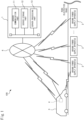
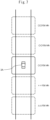
- FIG. 1 shows as one example of installation of ground power supply apparatuses 2, an example where a plurality of ground power supply apparatuses 2 are set consecutively along a road at predetermined intervals.
- a road at which ground power supply apparatuses 2 are installed will be referred to as an "electrified road" in accordance with need.
- FIG. 2 is a view showing one example of the configuration of a ground power supply apparatus 2 according to the present embodiment.
- the ground side communication device 23 is configured so as to enable communication between at least the server 1 and vehicle 3.
- Short range wireless communication is communication with a shorter communication distance compared with wide area wireless communication. For example, it is communication with a communication distance of less than 10 meters.
- various short range wireless communication schemes with short communication distances can be used. For example, communication based on any communication standard formulated by the IEEE, ISO, IEC, etc. (for example, Bluetooth ® , ZigBee ® ) can be used.
- RFID radio frequency identification
- DSRC dedicated short range communication
- the power transmission processing part 203 has one or more CPUs (central processing units) and their peripheral circuits.
- the power transmission processing part 203 runs various computer programs stored in the storage part 202 and comprehensively controls the overall operations of the ground power supply apparatus 2 and is, for example, a processor.
- the content of the processing performed at the power transmission processing part 203 and in turn the power transmission control device 20 will be explained later referring to FIG. 5 .
- the power reception device 31 is provided with a power reception side resonator 311 and a power reception circuit 312.
- the power reception side resonator 31 is a resonance circuit including a power reception coil and is configured to resonate at the same resonance frequency f 0 as the power transmission side resonator 221.
- the power reception circuit 312 is an electrical circuit provided with a rectifier and DC/DC converter and is configured to be controlled by the vehicle control device 30 to be able to convert AC power output from the power reception side resonator 311 to DC power by the rectifier and supply it through the DC/DC converter to the electric load 39.
- the electric load 39 for example, a battery, electric motor, etc. may be mentioned, but the invention is not particularly limited to this.
- the power reception circuit 312 is connected to a battery as the electric load 39.
- the vehicle side communication device 32 is configured to be able to communicate with at least the server 1 and a ground power supply apparatus 2.
- vehicle side communication device 32 is configured to be able to directly communicate with the ground side communication device 23 of the ground power supply apparatus 2 by short range wireless communication.
- the vehicle control device 30 is provided with a communication interface 301, storage part 302, and vehicle processing part 303.
- the storage part 302 has an HDD or SSD, optical recording medium, semiconductor memory, or other storage medium and stores various computer programs and data used for processing at the vehicle processing part 303.
- the vehicle processing part 303 has one or more CPUs and their peripheral circuits.
- the vehicle processing part 303 runs various computer programs stored in the server storage part 302 so as to comprehensively control the overall operation of the vehicle 3 and is for example a processor.
- the information device 4 is, for example, provided with a user interface 41 with which information can be input and output such as a navigation device or other vehicle-mounted terminal mounted in advance in the vehicle 3 or a mobile phone or tablet computer or other portable terminal held by the system user, a wireless communication device 42, a position measuring device 43, and an information control device 40.
- the user interface 41, wireless communication device 42, and position measuring device 43 are connected with the information control device 40 through a network 44 based on the CAN or other standard.
- the wireless communication device 42 is, for example, provided with an antenna and a signal processing circuit for performing various processing relating to wireless communication such as modulation and demodulation of a wireless signal.
- the wireless communication device 42 accesses a wireless base station connected to the network 6 (see FIG. 1 ) through a gateway etc. to thereby be connected to the network 6 through the wireless base station. Due to this, wireless communication is performed between the wireless communication device 42 and in turn the information device 4 and the server 1.
- the ground power supply apparatus 2 calculates the number of vehicles 3 for which the apparatus concerned will perform noncontact power supply (below, referred to as the "number of vehicles for supply with power") and transmits information relating to the number of vehicles for supply with power (below, referred to as the "information on number of vehicles for supply with power”) to the server 1.
- the number of vehicles for supply with power can, for example, be calculated by obtaining a grasp of the number of power transmission apparatuses 22 substantially simultaneously transmitting power based on detection signals of the power transmission sensors 223.
- the information on the number of vehicles for supply with power includes, in addition to the number of vehicles for supply with power of the apparatus concerned, for example, the position of installation of the apparatus concerned (latitude and longitude) and other identification information for differentiating the apparatus concerned from other ground power supply apparatuses.
- the number of vehicles for supply with power is calculated by the ground power supply apparatus 2 periodically.
- the ground power supply apparatus 2 transmits to the server 1 the information on the number of vehicles for supply with power relating to the number of vehicles for supply with power calculated each time calculating the information on number of vehicles for supply with power.
- the information device 4 transmits a signal requesting information on the charge for usage to the server 1 if the timing for requesting information on the charge for usage relating to the charge for usage of the ground power supply apparatus 2.
- the information device 4 starts periodic transmission of a signal requesting information on the charge for usage to the server 1.
- the signal requesting information on the charge for usage includes, for example, identification information of the information device 4 originating that signal (for example, MAC address etc.) and positional information of the information device 4 (in other words, positional information of the vehicle 3 associated with the information device 4).
- identification information of the information device 4 originating that signal for example, MAC address etc.
- positional information of the information device 4 in other words, positional information of the vehicle 3 associated with the information device 4.
- the vehicle control device 30 is provided with an automated driving control part for automatically performing driving operations relating to acceleration, steering, and braking of the vehicle 3, it is also possible to configure the automated driving control part so as to automatically control the vehicle 3 using information relating to the charges for usage of the ground power supply apparatuses 2 acquired by communicating with the server 1 (for example, information relating to the charges for usage of the ground power supply apparatuses 2 installed at least at one of the front in the advancing direction or rear in the advancing direction of the vehicle 3).
- the automated driving control part can be configured so as to automatically change the relative position with other vehicles based on the charge for usage of ground power supply apparatus.
- the automated driving control part can be configured so as to automatically change the relative position with other vehicles so that the charge for usage of the ground power supply apparatus 2 becomes lower.
- the information device 4 may calculate the presumed amount of the total charge for usage when running on a scheduled running route based on the charges for usage of the ground power supply apparatuses 2 on the scheduled running route and provide the calculated presumed amount of the total charge for usage to the system user.
- the scheduled running route it is also possible to display along with it another running route and the presumed amount of the total charge for usage when running on that other running route.
- the electric power demand is electric power demand from vehicles 3 to the ground power supply apparatuses 2.
- the server 1 is configured so as to set a charge for usage of a ground power supply apparatus 2 with a higher electric power demand from the vehicles 3 higher than a charge for usage of a ground power supply apparatus 2 with a lower electric power demand from the vehicles 3.
- a ground power supply apparatus 2 is configured to be able to supply power by noncontact to a plurality of vehicles 3.
- the server 1 is configured so as to set a charge for usage of a ground power supply apparatus 2 with a larger number of vehicles 3 for supply with power higher than a charge for usage of a ground power supply apparatus 2 with a smaller number of vehicles 3 for supply with power.
- information relating to the charges for usage of the ground power supply apparatuses 2 set based on the electric power demand is provided to the system user.
- a charge for usage of a ground power supply apparatus 2 is set higher the higher the electric power demand from vehicles 3 on the ground power supply apparatus 2. For this reason, for example, it is possible to prompt a system user with a low urgency of noncontact power supply to utilize another ground power supply apparatus 2 with a lower charge for usage or prompt him to suspend noncontact power supply, so it is possible to keep vehicles 3 desiring noncontact power supply from ending up concentrating at just some of the ground power supply apparatuses 2 and in turn just some of the electrified road sections.
- the information device 4 is configured so as to provide to the system user the information relating to the charge for usage of a ground power supply apparatus 2 installed at least at one of the front in the advancing direction or rear in the advancing direction of the vehicle 3 (moving body) associated with the information device 4.
- a ground power supply apparatus 2 As information relating to the charge for usage of a ground power supply apparatus 2, it is possible to provide the absolute price of the ground power supply apparatus 2 and possible to supply the relative price with the charge for usage of a reference ground power supply apparatus 2.
- the reference ground power supply apparatus 2 can be made the ground power supply apparatus supplying power to the vehicle 3 (moving body) associated with the information device 4.
- the present embodiment differs in the method of setting the charges for usage of the ground power supply apparatuses 2 from the first embodiment. Below, it will be explained focusing on the points of difference.
- the electric power demand was grasped from the current numbers of vehicles for supply with power of the ground power supply apparatuses 2.
- the electric power demand is grasped from the rates of power use [%] of the ground power supply apparatuses 2.
- the "rate of power use" of a ground power supply apparatus 2 is the ratio of the current amount of power used by the ground power supply apparatus 2 to the amount of power able to be supplied by the ground power supply apparatus 2.
- the ground power supply apparatus 2 calculates the rate of power use of the apparatus concerned and sends information relating to the rate of power use (below, referred to as the "information on the rate of power use") to the server 1.
- the information on the rate of power use includes, in addition to the rate of power use of the apparatus concerned, identification information for identifying the apparatus concerned from other ground power supply apparatuses and other various information required for setting the charge for usage. Note that, the rate of power use is periodically calculated by the ground power supply apparatus 2.
- the ground power supply apparatus 2 sends the rate of power use to the server 1 each time calculating it.
- the server 1 identifies the ground power supply apparatus 2 originating the information on the rate of power use based on the identification information contained in the information on the rate of power use and sets (updates) the charge for usage of the ground power supply apparatus 2 identified based on the rate of power use contained in the information on the rate of power use.
- the charge for usage of the ground power supply apparatus 2 is made higher since the higher the rate of power use, the higher the electric power demand from vehicles 3 with respect to the ground power supply apparatus 2 that can be judged.
- the server 1 is configured so as to set a charge for usage of a ground power supply apparatus 2 with a higher rate of power use higher than a charge for usage of a ground power supply apparatus 2 with a lower rate of power use.
- the electric power demand from the vehicles 3 to the ground power supply apparatuses 2 was grasped by communicating with the ground power supply apparatuses 2.
- the electric power demand from the vehicles 3 to the ground power supply apparatuses 2 is grasped by communicating with the vehicles 3.
- the vehicle 3 sends the server 1 vehicle information including the scheduled running route and current position of the vehicle concerned.
- the vehicle information is transmitted periodically.
- the method of acquiring the scheduled running route or current position is not particularly limited, but the scheduled running route can, for example, be acquired from a navigation device (not shown) mounted in the vehicle 3. Further, the current position, for example, can be acquired from a position measuring device (not shown) mounted in the vehicle 3.
- the ground power supply apparatus 2 is configured to be able to perform noncontact power supply for a plurality of vehicles 3 (moving bodies). Further, the server 1 is configured to calculate the estimated numbers of vehicles for supply with power of the ground power supply apparatuses 2 for each time frame and set the charges for usage of the ground power supply apparatuses 2 based on the estimated numbers of vehicles for supply with power of the ground power supply apparatuses 2 in the same time frame. Specifically, the server 1 is configured to set the charge for usage of a ground power supply apparatus 2 with a larger estimated number of vehicles for supply with power in the same time frame higher than the charge for usage of a ground power supply apparatus 2 with a smaller estimated number of vehicles for supply with power in the same time frame.
- the present embodiment differs in the method of setting the charges for usage of the ground power supply apparatuses 2 from the above embodiments. Below, it will be explained focusing on the points of difference.
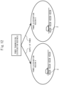
- the server 1 sets the charges for usage of the ground power supply apparatuses 2 installed in the power distribution regions based on the rates of power use of the power distribution regions. For example, in FIG. 12 , when the rate of power use of the power distribution region A is higher than the rate of power use of the power distribution region B, the server 1 makes the charge for usage of the ground power supply apparatuses 2 installed at the power distribution region A higher than the charge for usage of the ground power supply apparatuses 2 installed at the power distribution region B.
Landscapes
- Engineering & Computer Science (AREA)
- Business, Economics & Management (AREA)
- Power Engineering (AREA)
- Mechanical Engineering (AREA)
- Transportation (AREA)
- General Physics & Mathematics (AREA)
- Physics & Mathematics (AREA)
- Economics (AREA)
- Strategic Management (AREA)
- Development Economics (AREA)
- Computer Networks & Wireless Communication (AREA)
- Theoretical Computer Science (AREA)
- Marketing (AREA)
- General Business, Economics & Management (AREA)
- Health & Medical Sciences (AREA)
- Finance (AREA)
- Accounting & Taxation (AREA)
- General Health & Medical Sciences (AREA)
- Human Resources & Organizations (AREA)
- Primary Health Care (AREA)
- Tourism & Hospitality (AREA)
- Life Sciences & Earth Sciences (AREA)
- Atmospheric Sciences (AREA)
- Public Health (AREA)
- Water Supply & Treatment (AREA)
- Entrepreneurship & Innovation (AREA)
- Game Theory and Decision Science (AREA)
- Human Computer Interaction (AREA)
- Automation & Control Theory (AREA)
- Charge And Discharge Circuits For Batteries Or The Like (AREA)
- Electric Propulsion And Braking For Vehicles (AREA)
- Current-Collector Devices For Electrically Propelled Vehicles (AREA)
- Traffic Control Systems (AREA)
- Management, Administration, Business Operations System, And Electronic Commerce (AREA)
- Navigation (AREA)
Abstract
Description
- The present invention relates to a noncontact power supply system, server, information device, moving body, and control device of a moving body.
-
Japanese Unexamined Patent Publication No. 2019-526219 - If vehicles desiring noncontact power supply end up concentrating at just some ground power supply apparatuses, the supply of electric power is liable to become insufficient for the demand for electric power. Further, if trying to increase the electric power supply capacity to deal with such a situation, enormous capital investment is liable to become necessary.
- The present invention was made focusing on such a problem and has as its object to keep vehicles desiring noncontact power supply from ending up concentrating at just some ground power supply apparatuses.
- To solve this problem, the noncontact power supply system according to one aspect of the present invention is provided with an information device associated with a moving body and configured to provide information to a user of the moving body, the moving body configured to be able to receive noncontact power supply from ground power supply apparatuses, and a server configured to communicate with the information device. The server is configured to set charges for usage of ground power supply apparatuses based on electric power demand. The information device is configured to provide the user with information relating to the charges for usage of ground power supply apparatuses acquired by communicating with the server.
- Further, the server according to another aspect of the present invention is provided with a communication part configured to be able to communicate with an information device which is associated with a moving body and is configured to provide information to a user of the moving body, the moving body configured to be able to receive noncontact power supply from ground power supply apparatuses, and a control part. The control part is configured to set charges for usage of ground power supply apparatuses based on electric power demand and to transmit information relating to the set charges for usage of ground power supply apparatuses to the information device.
- Further, the information device according to another aspect of the present invention is a device associated with a moving body and configured to provide information to a user of the moving body. The moving body is configured to be able to receive noncontact power supply from ground power supply apparatuses, and the information device is provided with a communication part configured to be able to communicate with a server for setting charges for usage of ground power supply apparatuses based on electric power demand and a control part. The control part is configured to provide the user with information relating to the charges for usage of ground power supply apparatuses acquired by communicating with the server.
- Further, the moving body according to another aspect of the present invention is a moving body configure to be able to receive noncontact power supply from a ground power supply apparatus and is provided with a communication part configured to be able to communicate with a server for setting charges for usage of ground power supply apparatuses based on electric power demand and with an information part providing the user with information relating to the charges for usage of ground power supply apparatuses acquired by communicating with the server. The information part is configured to provide the user with information relating to the charges for usage of ground power supply apparatuses acquired by communicating with the server.
- Further, the control device according to another aspect of the present invention is a control device mounted in a moving body which is configure to be able to receive noncontact power supply from a ground power supply apparatus and is provided with a communication part configured to be able to communicate with a server for setting charges for usage of ground power supply apparatuses based on electric power demand and an information part providing the user with information relating to the charges for usage of ground power supply apparatuses acquired by communicating with the server. The information part is configured to provide the user with information relating to the charges for usage of ground power supply apparatuses acquired by communicating with the server.
- Further, the control device according to another aspect of the present invention is a control device mounted in a moving body which is configured to be able to receive noncontact power supply from a ground power supply apparatus and is provided with an automated driving control part for automatically performing driving operations of the moving body and a communication part configured to be able to communicate with a server for setting charges for usage of ground power supply apparatuses based on electric power demand. The automated driving control part is configured so as to use information relating to the charges for usage of ground power supply apparatuses acquired by communicating with the server so as to automatically control the moving body.
- According to these aspects of the present invention, the charges for usage of ground power supply apparatuses are set based on electric power demand, and information relating to the set charges for usage of ground power supply apparatuses is provided to the user of the ground power supply apparatus or automated driving of the moving body is performed based on that information. For this reason, the user of the ground power supply apparatus or the automated driving capable moving body becomes able to suitably select the ground power supply apparatus to use by, for example, comparing the situation at each time such as the level of urgency of power supply and the charges for usage of ground power supply apparatuses. As a result, vehicles can be dispersed, so it is possible to keep vehicles desiring noncontact power supply from ending up concentrating at just some of the ground power supply apparatuses.
-
-
FIG. 1 is a schematic view of the configuration of a noncontact power supply system. -
FIG. 2 is a schematic view of the configuration of ground power supply apparatuses. -
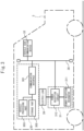
FIG. 3 is a schematic view of the configuration of a vehicle. -
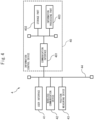
FIG. 4 is a schematic view of the configuration of an information device. -
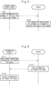
FIG. 5 is sequence diagram of operation for explaining contents of processing for setting a charge for usage according to a first embodiment of the present invention. -
FIG. 6 is sequence diagram of operation for explaining contents of processing for providing information according to the first embodiment of the present invention. -
FIG. 7 is a view explaining one example of a method of provision when providing information on a charge for usage of a ground power supply apparatus by an information device. -
FIG. 8 is a view explaining another example of a method of provision when providing information on a charge for usage of a ground power supply apparatus by an information device. -
FIG. 9 is sequence diagram of operation for explaining contents of processing for setting a charge for usage according to a second embodiment of the present invention. -
FIG. 10 is sequence diagram of operation for explaining contents of processing for setting a charge for usage according to a third embodiment of the present invention. -
FIG. 11 is sequence diagram of operation for explaining contents of processing for setting a charge for usage according to a fourth embodiment of the present invention. -
FIG. 12 is a view schematically showing the state of supply of electric power by a power transmission/distribution business to a plurality of power distribution regions. - Below, embodiments will be explained in detail while referring to the drawings. Note that, in the following explanation, similar component elements will be assigned the same reference notations.
-
FIG. 1 is a schematic view of the configuration of a noncontactpower supply system 100 according to a first embodiment of the present invention. - The noncontact
power supply system 100 according to the present embodiment is provided with a server 1, groundpower supply apparatuses 2, avehicle 3 as one example of a moving body, and aninformation device 4 associated with thevehicle 3 and providing various information to a user of thevehicle 3, that is, a user of the noncontact power supply system 100 (below, referred to as a "system user") and is configured to be able to transmit electric power by noncontact to thevehicle 3 from the ground power supply apparatuses 2 (noncontact power supply). The method of noncontact transmission of electric power is not particularly limited and can be suitably selected from magnetic coupling (electromagnetic induction) or electric field coupling, magnetic field resonance coupling (magnetic field resonance), electric field resonance coupling (electric field resonance), and other transmission systems. - Further, the noncontact
power supply system 100 is configured to set the charges for usage of the groundpower supply apparatuses 2 in accordance with electric power demand and to provide information relating to the set charges for usage of the groundpower supply apparatuses 2 through theinformation device 4 to the system user. In the present embodiment, the charge for usage of a groundpower supply apparatus 2 is made a value per 1 [kWh] amount of electric power supplied (yen/kWh), but the invention is not limited to this. - Note that,
FIG. 1 shows as one example of installation of groundpower supply apparatuses 2, an example where a plurality of groundpower supply apparatuses 2 are set consecutively along a road at predetermined intervals. In the following explanation, a road at which groundpower supply apparatuses 2 are installed will be referred to as an "electrified road" in accordance with need. - As shown in
FIG. 1 , the server 1 is provided with aserver communication part 11, aserver storage part 12, and aserver processing part 13. - The
server communication part 11 has a communication interface circuit for connecting the server 1 with anetwork 6 and is configured to enable communication with the groundpower supply apparatuses 2,vehicle 3, andinformation device 4 through thenetwork 6. - The
server storage part 12 has an HDD (hard disk drive) or SSD (solid state drive), optical recording medium, semiconductor memory, or other storage medium and stores various computer programs and data etc. used for processing at theserver processing part 13. - The
server processing part 13 has one or more CPUs (central processing units) and their peripheral circuits. Theserver processing part 13 runs various computer programs stored in theserver storage part 12 so as to comprehensively control the overall operation of the server 1 and is for example a processor. - If the server processing
part 13 and in turn the server 1 receives a signal requesting utilization of the noncontactpower supply system 100 from thevehicle 3, it confirms whether thevehicle 3 has the right to utilize the same. If confirmation is obtained, it transfers various information with the groundpower supply apparatuses 2 andvehicle 3 so as to enable thevehicle 3 to receive power supply from the groundpower supply apparatuses 2. Regarding details of this transfer, explanations will be omitted here since this is not a major part of the present invention. - Further, the
server processing part 13 sets the charges for usage of the groundpower supply apparatuses 2 based on the electric power demand fromvehicles 3 on the groundpower supply apparatuses 2 and sends information relating to the set charges for usage to theinformation device 4. The content of these processing performed by theserver processing part 13 will be explained later with reference toFIG. 5 and FIG. 6 . - Next, referring to
FIG. 2 andFIG. 3 , the configuration of a groundpower supply apparatus 2 according to the present embodiment and configuration of the parts of thevehicle 3 relating to noncontact power supply will be explained. -
FIG. 2 is a view showing one example of the configuration of a groundpower supply apparatus 2 according to the present embodiment. - As shown in
FIG. 2 , the groundpower supply apparatus 2 is provided with apower supply 21,power transmission device 22, groundside communication device 23, and powertransmission control device 20. Thepower transmission device 22 and the groundside communication device 23 are connected to the powertransmission control device 20 through aninternal network 24 of the groundpower supply apparatus 2 based on the CAN (controller area network) or other standard. Note thatFIG. 2 shows an example where the groundpower supply apparatus 2 has a plurality ofpower transmission devices 22, but it may also have a singlepower transmission device 22. - The
power supply 21 supplies power to thepower transmission device 22. Thepower supply 21 is, for example, a commercial AC power supply supplying single-phase AC power. Note that thepower supply 21 may also be another AC power supply supplying three-phase AC power or may be a DC power supply such as a fuel cell. Further,FIG. 2 shows an example where power is supplied to the individualpower transmission devices 22 by acommon power supply 21, but a dedicated power supply may also be prepared for each power transmission device to supply power. - The
power transmission device 22 is a device for transmitting power supplied from thepower supply 21 to avehicle 3 and is provided with a powertransmission side resonator 221 and apower transmission circuit 222. - The power
transmission side resonator 221 is a resonance circuit including a power transmission coil and is configured to resonate by a predetermined resonance frequency f0. In the present embodiment, the resonance frequency f0 is set to 85 kHz determined by the SAE TIR J2954 standard as the frequency band for noncontact power transmission, but the invention is not limited to this. - Note that while explained later referring to
FIG. 3 , thevehicle 3 is provided with a powerreception side resonator 311 corresponding to this powertransmission side resonator 221. The powerreception side resonator 311 is a resonance circuit including a power reception coil and is configured to resonate at the same resonance frequency f0 as the powertransmission side resonator 221. By making the powertransmission side resonator 221 resonate, the power transmission coil of the powertransmission side resonator 221 and the power reception coil of the powerreception side resonator 311 disposed spaced apart are magnetically coupled and power is transmitted by noncontact from thepower transmission device 22 to thepower reception device 31. - The
power transmission circuit 222 is an electrical circuit provided with a rectifier and inverter and is configured to be controlled by the powertransmission control device 20 to be able to convert AC power supplied from thepower supply 21 to DC power by the rectifier and to convert the DC power by the inverter to the desired AC power able to make the powertransmission side resonator 221 resonate and then supply it to the powertransmission side resonator 221. Note that the configuration of thepower transmission circuit 222 is not limited to such a configuration and may be suitably changed in accordance with the type of thepower supply 21. - Further, the
power transmission circuit 222 is provided with apower transmission sensor 223 for detecting whether power is being transmitted (in other words, whether noncontact power supply is being performed). Thepower transmission sensor 223, for example, includes a power transmission side current sensor detecting a current I1 flowing through the power transmission side resonator 221 (below, referred to as the "power transmission side current") and power transmission side voltage sensor detecting a voltage V1 applied to the power transmission side resonator 221 (below, referred to as the "power transmission side voltage"). The detection signal of thepower transmission sensor 223 is input to the powertransmission control device 20. - The ground
side communication device 23 is configured so as to enable communication between at least the server 1 andvehicle 3. - Specifically, the ground
side communication device 23 is configured so as to be able to access a wireless base station connected with the network 6 (seeFIG. 1 ) through a gateway etc. to thereby connect with thenetwork 6 through the wireless base station. Due to this, wide area wireless communication is performed between the groundside communication device 23 and the server 1 and the various information required for noncontact power supply to thevehicle 3 is exchanged with the server 1. Wide area wireless communication is communication with a longer communication distance compared with the later explained short range wireless communication. For example, it is communication with a communication distance of 10 meters to 10 kilometers. As wide area wireless communication, various wireless communication schemes with long communication distances can be used. For example, communication based on the 3GPP® and standards formulated by the IEEE such as the 4G, LTE, 5G, WiMAX, and other communication standards can be used. - Further, the ground
side communication device 23 is configured so as to directly perform short range wireless communication with a vehicleside communication device 32 mounted in thevehicle 3. Short range wireless communication is communication with a shorter communication distance compared with wide area wireless communication. For example, it is communication with a communication distance of less than 10 meters. As short range wireless communication, various short range wireless communication schemes with short communication distances can be used. For example, communication based on any communication standard formulated by the IEEE, ISO, IEC, etc. (for example, Bluetooth®, ZigBee®) can be used. As art for performing short range wireless communication, for example, RFID (radio frequency identification), DSRC (dedicated short range communication) etc. is used. - The power
transmission control device 20 is provided with acommunication interface 201,storage part 202, and powertransmission processing part 203. - The
communication interface 201 is a communication interface circuit for connecting the powertransmission control device 20 to theinternal network 24 of the groundpower supply apparatus 2. - The
storage part 202 has an HDD or SSD, optical recording medium, semiconductor memory, or other storage medium and stores various computer programs and data used for processing at the powertransmission processing part 203. - The power
transmission processing part 203 has one or more CPUs (central processing units) and their peripheral circuits. The powertransmission processing part 203 runs various computer programs stored in thestorage part 202 and comprehensively controls the overall operations of the groundpower supply apparatus 2 and is, for example, a processor. The content of the processing performed at the powertransmission processing part 203 and in turn the powertransmission control device 20 will be explained later referring toFIG. 5 . -
FIG. 3 is a view showing one example of the configuration of the part of thevehicle 3 according to the present embodiment mainly relating to noncontact power supply. - As shown in
FIG. 3 , thevehicle 3 is provided with apower receiving apparatus 31, a vehicleside communication device 32, and avehicle control device 30. Thepower receiving apparatus 31 and vehicleside communication device 32 are connected to thevehicle control device 30 through aninternal vehicle network 38 based on the CAN or other standard. - The
power reception device 31 is provided with a powerreception side resonator 311 and apower reception circuit 312. - The power
reception side resonator 311, as explained above, is a resonance circuit including a power reception coil and is configured to resonate at the same resonance frequency f0 as the powertransmission side resonator 221. - The
power reception circuit 312 is an electrical circuit provided with a rectifier and DC/DC converter and is configured to be controlled by thevehicle control device 30 to be able to convert AC power output from the powerreception side resonator 311 to DC power by the rectifier and supply it through the DC/DC converter to theelectric load 39. As theelectric load 39 , for example, a battery, electric motor, etc. may be mentioned, but the invention is not particularly limited to this. In the present embodiment, thepower reception circuit 312 is connected to a battery as theelectric load 39. - The vehicle
side communication device 32 is configured to be able to communicate with at least the server 1 and a groundpower supply apparatus 2. - Specifically, the vehicle
side communication device 32 is configured so as to be able to access a wireless base station connected with the network 6 (seeFIG. 1 ) through a gateway etc. to thereby connect with thenetwork 6 through the wireless base station. Due to this, wide area wireless communication is performed between the vehicleside communication device 32 and the server 1 and the various information required for noncontact power supply from thepower supply apparatus 2 is exchanged with the server 1. - Further, the vehicle
side communication device 32 is configured to be able to directly communicate with the groundside communication device 23 of the groundpower supply apparatus 2 by short range wireless communication. - The
vehicle control device 30 is provided with acommunication interface 301,storage part 302, andvehicle processing part 303. - The
communication interface 301 is a communication interface circuit for connecting thevehicle control device 30 to theinternal vehicle network 38. - The
storage part 302 has an HDD or SSD, optical recording medium, semiconductor memory, or other storage medium and stores various computer programs and data used for processing at thevehicle processing part 303. - The
vehicle processing part 303 has one or more CPUs and their peripheral circuits. Thevehicle processing part 303 runs various computer programs stored in theserver storage part 302 so as to comprehensively control the overall operation of thevehicle 3 and is for example a processor. -
FIG. 4 is a schematic view of the configuration of theinformation device 4. - The
information device 4 is, for example, provided with auser interface 41 with which information can be input and output such as a navigation device or other vehicle-mounted terminal mounted in advance in thevehicle 3 or a mobile phone or tablet computer or other portable terminal held by the system user, awireless communication device 42, aposition measuring device 43, and aninformation control device 40. Theuser interface 41,wireless communication device 42, andposition measuring device 43 are connected with theinformation control device 40 through anetwork 44 based on the CAN or other standard. - The
user interface 41 is provided with a display and speaker for providing various information to the system user and a touch panel for enabling the system user to input information on the display. Further, theuser interface 41 generates a signal corresponding to various input operations performed by the system user and sends the signal to theinformation control device 40. Further, theuser interface 41 displays various display use information received from theinformation control device 40 on the display to provide it to the system user. - The
wireless communication device 42 is, for example, provided with an antenna and a signal processing circuit for performing various processing relating to wireless communication such as modulation and demodulation of a wireless signal. Thewireless communication device 42 accesses a wireless base station connected to the network 6 (seeFIG. 1 ) through a gateway etc. to thereby be connected to thenetwork 6 through the wireless base station. Due to this, wireless communication is performed between thewireless communication device 42 and in turn theinformation device 4 and the server 1. - The
position measuring device 43 is, for example, provided with a receiver for receiving a GNSS (global navigation satellite system) signal and a processing circuit for calculating the position of theinformation device 4 from the GNSS signal. Theposition measuring device 43 measures the position of theinformation device 4 based on the GNSS signal and sends positional information to theinformation control device 40 each time measuring the position of theinformation device 4. - The
information control device 40 is provided with acommunication interface 401, astorage part 402, and aninformation processing part 403. - The
communication interface 401 is provided with an interface circuit for connecting theinformation control device 40 to thenetwork 44. - The
storage part 402, for example, has an HDD or SSD, optical recording medium, semiconductor memory, or other storage medium. Thestorage part 402 stores various computer programs and various data used by theinformation processing part 403. - The
information processing part 403, for example, is a processor having one or more CPUs and their peripheral circuits. Theinformation processing part 403 may further be provided with other processing circuits such as logical operation units and numerical operation units. Theinformation processing part 403 runs various computer programs stored in thestorage part 402. The content of the processing performed by theinformation processing part 403 and in turn theinformation control device 40 will be explained later with reference toFIG. 6 . -
FIG. 5 is a sequence diagram of operation for explaining one example of the contents of processing (computer program) performed at the server 1 and a ground power supply apparatus 2 (in more detail, theserver processing part 13 and power transmission control device 20) for setting the charges for usage of the groundpower supply apparatuses 2. - At step S101, the ground
power supply apparatus 2 calculates the number ofvehicles 3 for which the apparatus concerned will perform noncontact power supply (below, referred to as the "number of vehicles for supply with power") and transmits information relating to the number of vehicles for supply with power (below, referred to as the "information on number of vehicles for supply with power") to the server 1. The number of vehicles for supply with power can, for example, be calculated by obtaining a grasp of the number ofpower transmission apparatuses 22 substantially simultaneously transmitting power based on detection signals of thepower transmission sensors 223. - The information on the number of vehicles for supply with power includes, in addition to the number of vehicles for supply with power of the apparatus concerned, for example, the position of installation of the apparatus concerned (latitude and longitude) and other identification information for differentiating the apparatus concerned from other ground power supply apparatuses. Note that, the number of vehicles for supply with power is calculated by the ground
power supply apparatus 2 periodically. The groundpower supply apparatus 2 transmits to the server 1 the information on the number of vehicles for supply with power relating to the number of vehicles for supply with power calculated each time calculating the information on number of vehicles for supply with power. - At step S102, if receiving information on number of vehicles for supply with power, the server 1 identifies the ground
power supply apparatus 2 originating the information on the number of vehicles for supply with power based on the identification information contained in the information on the number of vehicles for supply with power and sets (updates) the charge for usage of the groundpower supply apparatus 2 identified based on the number of vehicles for supply with power contained in the information on the number of vehicles for supply with power. The charge for usage of the groundpower supply apparatus 2 is made higher since the greater the number of vehicles for supply with power, the higher the electric power demand (that is, the load of the ground power supply apparatus 2) from thevehicles 3 to the groundpower supply apparatus 2 that can be judged. -
FIG. 6 is a sequence diagram of operation for explaining one example of the contents of processing (computer program) performed at the server 1 and a ground power supply apparatus 2 (in more detail, theserver processing part 13 and information control device 40) for providing the charges for usage of the groundpower supply apparatuses 2 to the system user. - At step S111, the
information device 4 transmits a signal requesting information on the charge for usage to the server 1 if the timing for requesting information on the charge for usage relating to the charge for usage of the groundpower supply apparatus 2. In the present embodiment, if transmission of information on the charge for usage of the groundpower supply apparatus 2 is requested by a system user through auser interface 41, theinformation device 4 starts periodic transmission of a signal requesting information on the charge for usage to the server 1. - The signal requesting information on the charge for usage includes, for example, identification information of the
information device 4 originating that signal (for example, MAC address etc.) and positional information of the information device 4 (in other words, positional information of thevehicle 3 associated with the information device 4). In addition to this, for example, if able to acquire route information relating to the scheduled running route of thevehicle 3 associated with theinformation device 4, it is also possible to include the route information in the signal requesting information on the charge for usage. - At step S112, if receiving a signal requesting information on the charge for usage, the server 1 refers to the positional information included in the signal and sends to the
information device 4 originating the signal the information on the charges for usage of the groundpower supply apparatuses 2 in the surroundings of theinformation device 4. At this time, if a groundpower supply apparatus 2 which finished transmitting information on the charge for usage in the previous processing is included, it is also possible to transmit the information on the charges for usage only for the groundpower supply apparatuses 2 with changes in the charges for usage among them. Due to this, the communication load can be reduced. - At step S113, if receiving information on the charges for usage of the ground
power supply apparatuses 2 in its surroundings, theinformation device 4 provides that information to the system user through theuser interface 41. - For example, the
information device 4, as shown inFIG. 7 , can display information on the charge for usage of the groundpower supply apparatus 2 at the current position of thevehicle 3 associated with the device concerned and information on the charges for usage of the groundpower supply apparatuses 2 positioned at the front in the advancing direction or rear in the advancing direction of thevehicle 3 associated with the device concerned together with anicon 3A of thevehicle 3 associated with the device concerned on a display to provide them to the system user. - The information on the charge for usage provided to the system user may be an absolute price or may be a relative price based on the charge for usage of the ground
power supply apparatus 2 at the current position of thevehicle 3 associated with theinformation device 4. At this time, to facilitate obtaining a grasp of the charge for usage, in the display, it is also possible to suitably color the display of the charge or the location in accordance with the information on the charge for usage. For example, there is the method of display high charges and locations in red and low charges and locations in blue etc. - Further, as shown in
FIG. 8 , for example, if vehicle-vehicle communication etc. can be used to acquire from another vehicle positioned at the front in the advancing direction or rear in the advancing direction of thevehicle 3 associated with the device concerned the information on whether the other vehicle is receiving noncontact power supply, it is also possible to display anicon 3B of the other vehicle receiving power positioned at the front in the advancing direction or rear in the advancing direction of thevehicle 3 associated with the device concerned on the display together with anicon 3A of thevehicle 3 associated with the device concerned to provide that to the system user. Note that, inFIG. 8 , to facilitate differentiation of thevehicle 3 associated with the device concerned and the other vehicle, theicon 3B of the other vehicle is made an ellipse. By display in this way, a driver can obtain a grasp of the fact of charges being higher due to a large number of other vehicles receiving power near thevehicle 3 associated with the device concerned. It is possible to lower the charge by departing from the group of vehicles for supply with power (section in which groundpower supply apparatus 2 with large number of other vehicles receiving power supply is installed). - Note that, in the example shown in
FIG. 7 andFIG. 8 , the method of informing the driver of the charge for use was shown, but, for example, if thevehicle 3 associated with the device concerned is an automated driving vehicle in which driving operations relating to acceleration, steering, and braking are automatically performed by thevehicle control device 30, it is also possible to provide thevehicle control device 30 with the information on the charge for usage etc. and automatically make thevehicle 3 run to depart from the group of vehicles for supply with power so that the charge for usage becomes cheaper. That is, if thevehicle control device 30 is provided with an automated driving control part for automatically performing driving operations relating to acceleration, steering, and braking of thevehicle 3, it is also possible to configure the automated driving control part so as to automatically control thevehicle 3 using information relating to the charges for usage of the groundpower supply apparatuses 2 acquired by communicating with the server 1 (for example, information relating to the charges for usage of the groundpower supply apparatuses 2 installed at least at one of the front in the advancing direction or rear in the advancing direction of the vehicle 3). Specifically, the automated driving control part can be configured so as to automatically change the relative position with other vehicles based on the charge for usage of ground power supply apparatus. Further, the automated driving control part can be configured so as to automatically change the relative position with other vehicles so that the charge for usage of the groundpower supply apparatus 2 becomes lower. - Further, for example, if it is possible to calculate the scheduled running route up to the destination of the
vehicle 3 associated with the device concerned or to acquire it by a method such as communication with the server 1 orvehicle 3, theinformation device 4 may calculate the presumed amount of the total charge for usage when running on a scheduled running route based on the charges for usage of the groundpower supply apparatuses 2 on the scheduled running route and provide the calculated presumed amount of the total charge for usage to the system user. At this time, in addition to the scheduled running route, it is also possible to display along with it another running route and the presumed amount of the total charge for usage when running on that other running route. - The noncontact
power supply system 100 according to the present embodiment explained above is provided with aninformation device 4 associated with a vehicle (moving body) able to receive noncontact power supply from the groundpower supply apparatuses 2 and providing information to the user of thevehicle 3 as the system user and with a server 1 communicating with theinformation device 4. Further, the server 1 is configured to set the charges for usage of the groundpower supply apparatuses 2 based on the electric power demand. Theinformation device 4 is configured so as to provide the system user with information relating to the charges for usage of the groundpower supply apparatuses 2 acquired by communicating with the server 1. - In the present embodiment, the electric power demand is electric power demand from
vehicles 3 to the groundpower supply apparatuses 2. The server 1 is configured so as to set a charge for usage of a groundpower supply apparatus 2 with a higher electric power demand from thevehicles 3 higher than a charge for usage of a groundpower supply apparatus 2 with a lower electric power demand from thevehicles 3. Specifically, in the present embodiment, a groundpower supply apparatus 2 is configured to be able to supply power by noncontact to a plurality ofvehicles 3. The server 1 is configured so as to set a charge for usage of a groundpower supply apparatus 2 with a larger number ofvehicles 3 for supply with power higher than a charge for usage of a groundpower supply apparatus 2 with a smaller number ofvehicles 3 for supply with power. - In this way, according to the present embodiment, information relating to the charges for usage of the ground
power supply apparatuses 2 set based on the electric power demand is provided to the system user. A charge for usage of a groundpower supply apparatus 2 is set higher the higher the electric power demand fromvehicles 3 on the groundpower supply apparatus 2. For this reason, for example, it is possible to prompt a system user with a low urgency of noncontact power supply to utilize another groundpower supply apparatus 2 with a lower charge for usage or prompt him to suspend noncontact power supply, so it is possible to keepvehicles 3 desiring noncontact power supply from ending up concentrating at just some of the groundpower supply apparatuses 2 and in turn just some of the electrified road sections. - Further, the
information device 4 according to the present embodiment is configured so as to acquire information relating to a changed charge for usage from the server 1 and again provide it to the system user if the charge for usage of the groundpower supply apparatus 2 provided to the system user has changed by greater than or equal to a predetermined value. - Due to this, it is possible to keep down the communication load between the server 1 and the
information device 4. - Further, the
information device 4 according to the present embodiment is configured so as to provide to the system user the information relating to the charge for usage of a groundpower supply apparatus 2 installed at least at one of the front in the advancing direction or rear in the advancing direction of the vehicle 3 (moving body) associated with theinformation device 4. As information relating to the charge for usage of a groundpower supply apparatus 2, it is possible to provide the absolute price of the groundpower supply apparatus 2 and possible to supply the relative price with the charge for usage of a reference groundpower supply apparatus 2. The reference groundpower supply apparatus 2 can be made the ground power supply apparatus supplying power to the vehicle 3 (moving body) associated with theinformation device 4. - Due to this, the system user can easily obtain a grasp of the charge for usage of a ground
power supply apparatus 2 in the surroundings. - Further, the
information device 4 according to the present embodiment is configured to further provide the system user with information relating to anothervehicle 3 when there is anothervehicle 3 for supply with power at a groundpower supply apparatus 2 installed at least at one of the front in the advancing direction or rear in the advancing direction of thevehicle 3 associated with that device. - Due to this, the system user becomes able to easily obtain a visual grasp of the degree of congestion at a ground
power supply apparatus 2 in the surroundings. - Further, the
information device 4 according to the present embodiment is configured to calculate the presumed amount of the total charge for usage when running on a scheduled running route based on the scheduled running route of the vehicle 3 (moving body) associated with the device concerned and the charges for usage of the groundpower supply apparatuses 2 on the scheduled running route and provides that presumed amount to the system user as information relating to the charges for usage of the groundpower supply apparatuses 2. - Due to this, for the system user, change of the running route in accordance with the charge for usage becomes easy, so it is possible to prompt dispersion of the
vehicles 3 and keepvehicles 3 desiring noncontact power supply from ending up concentrating at just some of the groundpower supply apparatuses 2 and in turn just some of the electrified road sections. - Note that, if the
information device 4 is a navigation device or other vehicle-mounted terminal mounted in advance in avehicle 3, the vehicle 3 (moving body) can be understood as being provided with a communication part configured to be able to communicate with a server 1 for setting charges for usage of groundpower supply apparatuses 2 based on electric power demand and with an information part providing the user with information relating to the charges for usage of groundpower supply apparatuses 2 acquired by communicating with the server 1. Further, in that case, thevehicle control device 30 may also be given the function of theinformation control device 40. That is, thevehicle control device 30 may be provided with a communication part configured to be able to communicate with a server 1 for setting charges for usage of groundpower supply apparatuses 2 based on electric power demand and with an information part providing the user with information relating to the charges for usage of groundpower supply apparatuses 2 acquired by communicating with the server 1. - Next, a second embodiment of the present invention will be explained. The present embodiment differs in the method of setting the charges for usage of the ground
power supply apparatuses 2 from the first embodiment. Below, it will be explained focusing on the points of difference. - In the above-mentioned first embodiment, in setting the charges for usage of the ground
power supply apparatuses 2 based on electric power demand, the electric power demand was grasped from the current numbers of vehicles for supply with power of the groundpower supply apparatuses 2. As opposed to this, in the present embodiment, the electric power demand is grasped from the rates of power use [%] of the groundpower supply apparatuses 2. The "rate of power use" of a groundpower supply apparatus 2 is the ratio of the current amount of power used by the groundpower supply apparatus 2 to the amount of power able to be supplied by the groundpower supply apparatus 2. -
FIG. 9 is a sequence diagram of operation for explaining one example of the contents of processing (computer program) according to the present embodiment performed at the server 1 and a ground power supply apparatus 2 (in more detail, theserver processing part 13 and power transmission control device 20) for setting the charges for usage of the groundpower supply apparatuses 2. - At step S201, the ground
power supply apparatus 2 calculates the rate of power use of the apparatus concerned and sends information relating to the rate of power use (below, referred to as the "information on the rate of power use") to the server 1. The information on the rate of power use includes, in addition to the rate of power use of the apparatus concerned, identification information for identifying the apparatus concerned from other ground power supply apparatuses and other various information required for setting the charge for usage. Note that, the rate of power use is periodically calculated by the groundpower supply apparatus 2. The groundpower supply apparatus 2 sends the rate of power use to the server 1 each time calculating it. - At step S202, if receiving information on a rate of power use, the server 1 identifies the ground
power supply apparatus 2 originating the information on the rate of power use based on the identification information contained in the information on the rate of power use and sets (updates) the charge for usage of the groundpower supply apparatus 2 identified based on the rate of power use contained in the information on the rate of power use. The charge for usage of the groundpower supply apparatus 2 is made higher since the higher the rate of power use, the higher the electric power demand fromvehicles 3 with respect to the groundpower supply apparatus 2 that can be judged. - The server 1 according to the present embodiment explained above is configured so as to set a charge for usage of a ground
power supply apparatus 2 with a higher rate of power use higher than a charge for usage of a groundpower supply apparatus 2 with a lower rate of power use. - By doing this as well, in the same way as the first embodiment, for example, it is possible to prompt a system user with a low urgency of noncontact power supply to utilize another ground
power supply apparatus 2 with a low charge for usage or prompt him to suspend noncontact power supply, so it is possible to keepvehicles 3 desiring noncontact power supply from ending up concentrating at just some of the groundpower supply apparatuses 2 and in turn just some of the electrified road sections. - Next, a third embodiment of the present invention will be explained. The present embodiment differs in the method of setting the charges for usage of the ground
power supply apparatuses 2 from the above embodiments. Below, it will be explained focusing on the points of difference. - In the embodiments explained above, the electric power demand from the
vehicles 3 to the groundpower supply apparatuses 2 was grasped by communicating with the groundpower supply apparatuses 2. As opposed to this, in the present embodiment, the electric power demand from thevehicles 3 to the groundpower supply apparatuses 2 is grasped by communicating with thevehicles 3. -
FIG. 10 is a sequence diagram of operation for explaining one example of the contents of processing (computer program) according to the present embodiment performed at the server 1 and the vehicle 3 (in more detail, theserver processing part 13 and vehicle control device 30) for setting the charges for usage of the groundpower supply apparatuses 2. - At step S301, the
vehicle 3 sends the server 1 vehicle information including the scheduled running route and current position of the vehicle concerned. The vehicle information is transmitted periodically. The method of acquiring the scheduled running route or current position is not particularly limited, but the scheduled running route can, for example, be acquired from a navigation device (not shown) mounted in thevehicle 3. Further, the current position, for example, can be acquired from a position measuring device (not shown) mounted in thevehicle 3. - At step S302, the server 1 predicts the time frames in which the
vehicles 3 will pass the groundpower supply apparatuses 2 based on the vehicle information including the scheduled running routes and current positions received from thevehicles 3 and calculates the numbers ofvehicles 3 passing the groundpower supply apparatuses 2 for each time frame. That is, the server 1 calculates the estimated number of vehicles for supply with power for each time frame of the groundpower supply apparatuses 2. Further, the server 1 sets the charges for usage of the groundpower supply apparatuses 2 for each time frame based on the estimated numbers of vehicles for supply with power for each time frame of the groundpower supply apparatuses 2. Specifically, the server 1 sets the charges for usage of the groundpower supply apparatuses 2 for each time frame so that, when compared at the same time frame, a groundpower supply apparatus 2 with a greater estimated number of vehicles for supply with power becomes higher in charge for usage than a groundpower supply apparatus 2 with a lesser estimated number of vehicles for supply with power. - The ground
power supply apparatus 2 according to the present embodiment explained above is configured to be able to perform noncontact power supply for a plurality of vehicles 3 (moving bodies). Further, the server 1 is configured to calculate the estimated numbers of vehicles for supply with power of the groundpower supply apparatuses 2 for each time frame and set the charges for usage of the groundpower supply apparatuses 2 based on the estimated numbers of vehicles for supply with power of the groundpower supply apparatuses 2 in the same time frame. Specifically, the server 1 is configured to set the charge for usage of a groundpower supply apparatus 2 with a larger estimated number of vehicles for supply with power in the same time frame higher than the charge for usage of a groundpower supply apparatus 2 with a smaller estimated number of vehicles for supply with power in the same time frame. - In this way, it is possible to predict the numbers of
vehicles 3 which will pass the groundpower supply apparatuses 2 for each time frame and predict the estimated numbers of vehicles for supply with power (that is, the estimated numbers of vehicles passing) for each time frame so as to predict the electric power demand from thevehicles 3 for the groundpower supply apparatuses 2 for each time frame to set a suitable charge for usage. For this reason, for example, it is possible to prompt a user desiring to save on the charge for usage of a groundpower supply apparatus 2 etc. to change the running route so as to run on an electrified road at which a groundpower supply apparatus 2 with a lower charge for usage than the current schedule running route is installed, so it is possible to keepvehicles 3 desiring noncontact power supply from ending up concentrating at just some of the groundpower supply apparatuses 2 and in turn just some of the electrified road sections. - Next, a fourth embodiment of the present invention will be explained. The present embodiment differs in the method of setting the charges for usage of the ground
power supply apparatuses 2 from the above embodiments. Below, it will be explained focusing on the points of difference. - In the embodiments explained above, the charges for usage of the ground
power supply apparatuses 2 were set based on the electric power demand on the groundpower supply apparatuses 2. As opposed to this, in the present embodiment, the charges for usage of the groundpower supply apparatuses 2 are set based on the electric power demands of entire regions in which the groundpower supply apparatuses 2 are installed. -
FIG. 11 is a sequence diagram of operation for explaining one example of the contents of processing for setting charges for usage (computer program) according to the present embodiment performed at the server 1 (in more detail, the server processing part 13) for setting the charges for usage of the groundpower supply apparatuses 2. - At step S401, the server 1, for example, requests that a power transmission/distribution business (for example, electric power company) shown in
FIG. 12 provide information relating to the rates of power use of the power distribution regions of the power transmission/distribution business. This request is performed periodically. Note that,FIG. 12 illustrates two power distribution regions A, B as the power distribution regions of the power transmission/distribution business. Further, the rate of power use [%] of a power distribution region is the ratio of the current amount of power used by the power distribution region to the amount of power able to be supplied by the power distribution region. - At step S402, if receiving information relating to the rates of power use of the power distribution regions from the power transmission/distribution business, the server 1 sets the charges for usage of the ground
power supply apparatuses 2 installed in the power distribution regions based on the rates of power use of the power distribution regions. For example, inFIG. 12 , when the rate of power use of the power distribution region A is higher than the rate of power use of the power distribution region B, the server 1 makes the charge for usage of the groundpower supply apparatuses 2 installed at the power distribution region A higher than the charge for usage of the groundpower supply apparatuses 2 installed at the power distribution region B. - In the present embodiment explained above, the electric power demand is the electric power demand of the region in which the ground
power supply apparatuses 2 are set. The server 1 is configured to set a charge for usage of a groundpower supply apparatus 2 set in a region with a high rate of power use higher than a charge for usage of a groundpower supply apparatus 2 set in a region with a low rate of power use. - Due to this, for example, even a user desiring to save on the charge for usage of the ground
power supply apparatus 2 etc. can be prompted to run in a power distribution region with a lower charge for usage of the groundpower supply apparatus 2, so it is possible to keepvehicles 3 desiring noncontact power supply from ending up concentrating in some power distribution regions. - Above, embodiments of the present invention were explained, but the above embodiments just show some of the examples of application of the present invention and are not intended to limit the technical scope of the present invention to the specific constitutions of the above embodiments.
-
- 1
- server
- 2
- ground power supply apparatus
- 3
- vehicle (moving body)
- 4
- information device
- 100
- noncontact power supply system
Claims (24)
- A noncontact power supply system, whereinthe noncontact power supply system comprises:an information device associated with a moving body and configured to provide information to a user of the moving body, the moving body configured to be able to receive noncontact power supply from ground power supply apparatuses; anda server configured to communicate with the information device, andthe server is configured to set charges for usage of ground power supply apparatuses based on electric power demand, andthe information device is configured to provide the user with information relating to the charges for usage of ground power supply apparatuses acquired by communicating with the server.
- The noncontact power supply system according to claim 1, wherein
the electric power demand is electric power demand from the moving body with respect to the ground power supply apparatuses. - The noncontact power supply system according to claim 1 or claim 2, wherein
the server makes the charge for usage of a ground power supply apparatus with high electric power demand from the moving body higher than the charge for usage of a ground power supply apparatus with a low electric power demand from the moving body. - The noncontact power supply system according to claim 1, whereina ground power supply apparatus is configured to be able to supply power by noncontact to a plurality of moving bodies, andthe server is configured to make a charge for usage of a ground power supply apparatus with a larger number of moving bodies for supply with power higher than a charge for usage of a ground power supply apparatus with a smaller number of moving bodies for supply with power.
- The noncontact power supply system according to claim 1, wherein .a ground power supply apparatus is configured to be able to supply power by noncontact to a plurality of moving bodies, andthe server is configured to:calculate estimated numbers of vehicles for supply with power of the ground power supply apparatuses; andset charges for usage of the ground power supply apparatuses based on the estimated numbers of vehicles for supply with power of the ground power supply apparatuses in the same time frame.
- The noncontact power supply system according to claim 5, wherein
the server is configured to make a charge for usage of a ground power supply apparatus with a larger estimated number of vehicles for supply with power in the same time frame higher than a charge for usage of a ground power supply apparatus with a smaller estimated number of vehicles for supply with power in the same time frame. - The noncontact power supply system according to claim 1, wherein
the server is configured to make a charge for usage of a ground power supply apparatus with a higher rate of power use higher than a charge for usage of a ground power supply apparatus with lower rate of power use. - The noncontact power supply system according to claim 1, wherein
the electric power demand is electric power demand of the region in which the ground power supply apparatuses are installed. - The noncontact power supply system according to claim 1 or claim 8, wherein
the server is configured to make a charge for usage of a ground power supply apparatus installed in a region with a higher rate of power use higher than a charge for usage of a ground power supply apparatus installed in a region with a lower rate of power use. - The noncontact power supply system according to any one of claim 1 to claim 9, wherein
the information device is configured to acquire information relating to a charge for usage after change from the server and providing it again to the user if a charge for usage of a ground power supply apparatus provided to the user has changed by greater than or equal to a predetermined value. - The noncontact power supply system according to any one of claim 1 to claim 10, wherein
the information device is configured to provide the user with information relating to a charge for usage of a ground power supply apparatus installed at least at one of a front in an advancing direction or a rear in the advancing direction of the moving body associated with the information device. - The noncontact power supply system according to any one of claim 1 to claim 11, wherein
the information device is configured to provide the user with an absolute price of a ground power supply apparatus as information relating to the charge for usage of the ground power supply apparatus. - The noncontact power supply system according to any one of claim 1 to claim 12, wherein
the information device is configured to provide the user with a relative price with respect to a charge for usage of a reference ground power supply apparatus as information relating to the charge for usage of the ground power supply apparatus. - The noncontact power supply system according to claim 13, wherein
the reference ground power supply apparatus is a ground power supply apparatus able to supply power to the moving body associated with the information device. - The noncontact power supply system according to any one of claim 1 to claim 14, wherein
the information device is configured to further provide the user with information relating to another moving body when there is another moving body for supply of power present at a ground power supply apparatus installed at least at one of a front in an advancing direction or a rear in the advancing direction of the moving body associated with the device. - The noncontact power supply system according to any one of claim 1 to claim 15, wherein
the information device is configured to:calculate a presumed amount of total charge for usage when running on a scheduled running route based on the scheduled running route of the moving body associated with the information device and the charges for usage of the ground power supply apparatuses on the scheduled running route; andprovide the user with the presumed amount as information relating to the charges for usage of ground power supply apparatuses. - A server, wherein:the sever comprises:a communication part configured to be able to communicate with an information device which is associated with a moving body and is configured to provide information to a user of the moving body, the moving body configured to be able to receive noncontact power supply from ground power supply apparatuses; anda control part, andthe control part is configured to:set charges for usage of ground power supply apparatuses based on electric power demand; andtransmit information relating to the set charges for usage of ground power supply apparatuses to the information device.
- An information device associated with a moving body and configured to provide information to a user of the moving body, whereinthe moving body is configured to be able to receive noncontact power supply from ground power supply apparatuses, andthe information device comprises:a communication part configured to be able to communicate with a server for setting charges for usage of ground power supply apparatuses based on electric power demand; anda control part, andthe control part is configured to provide the user with information relating to the charges for usage of ground power supply apparatuses acquired by communicating with the server.
- A moving body configured to be able to receive noncontact power supply from a ground power supply apparatus, whereinthe moving body comprises:a communication part configured to be able to communicate with a server for setting charges for usage of ground power supply apparatuses based on electric power demand; andan information part configured to provide the user with information relating to the charges for usage of ground power supply apparatuses acquired by communicating with the server, andthe information part is configured to provide the user with information relating to the charges for usage of ground power supply apparatuses acquired by communicating with the server.
- A control device mounted in a moving body which is configured to be able to receive noncontact power supply from a ground power supply apparatus, whereinthe control device comprises:a communication part configured to be able to communicate with a server for setting charges for usage of ground power supply apparatuses based on electric power demand; andan information part configured to provide the user with information relating to the charges for usage of ground power supply apparatuses acquired by communicating with the server, andthe information part is configured to provide the user with information relating to the charges for usage of ground power supply apparatuses acquired by communicating with the server.
- A control device mounted in a moving body which is configured to be able to receive noncontact power supply from a ground power supply apparatus, whereinthe control device comprises:an automated driving control part for automatically performing driving operations of the moving body; anda communication part configured to be able to communicate with a server for setting charges for usage of ground power supply apparatuses based on electric power demand, andthe automated driving control part is configured to use information relating to the charges for usage of ground power supply apparatuses acquired by communicating with the server so as to automatically control the moving body.
- The control device of a moving body according to claim 21, wherein
the information is information relating to a charge for usage of a ground power supply apparatus installed at least at one of a front in an advancing direction or a rear in the advancing direction of the moving body. - The control device of a moving body according to claim 21 or claim 22, wherein
the automated driving control part is configured to automatically change a relative position with another vehicle based on the charge for usage of the ground power supply apparatus. - The control device of a moving body according to any one of claim 21 to claim 23, wherein
the automated driving control part is configured to automatically change a relative position with another vehicle so that the charge for usage of the ground power supply apparatus becomes cheaper.
Applications Claiming Priority (2)
| Application Number | Priority Date | Filing Date | Title |
|---|---|---|---|
| JP2022093137A JP7764319B2 (en) | 2022-06-08 | 2022-06-08 | Wireless power supply system, server, and mobile control device |
| PCT/JP2023/020481 WO2023238771A1 (en) | 2022-06-08 | 2023-06-01 | Contactless power supply system, server, information providing device, mobile object, and mobile object control device |
Publications (2)
| Publication Number | Publication Date |
|---|---|
| EP4538955A1 true EP4538955A1 (en) | 2025-04-16 |
| EP4538955A4 EP4538955A4 (en) | 2025-10-22 |
Family
ID=89118345
Family Applications (1)
| Application Number | Title | Priority Date | Filing Date |
|---|---|---|---|
| EP23819751.1A Pending EP4538955A4 (en) | 2022-06-08 | 2023-06-01 | CONTACTLESS POWER SUPPLY SYSTEM, SERVER, INFORMATION PROVIDING DEVICE, MOBILE OBJECT, AND MOBILE OBJECT CONTROL DEVICE |
Country Status (5)
| Country | Link |
|---|---|
| US (1) | US20250348957A1 (en) |
| EP (1) | EP4538955A4 (en) |
| JP (1) | JP7764319B2 (en) |
| CN (1) | CN119278463A (en) |
| WO (1) | WO2023238771A1 (en) |
Family Cites Families (7)
| Publication number | Priority date | Publication date | Assignee | Title |
|---|---|---|---|---|
| US11183001B2 (en) * | 2010-01-29 | 2021-11-23 | Chargepoint, Inc. | Electric vehicle charging station host definable pricing |
| KR20120100852A (en) * | 2012-07-23 | 2012-09-12 | 박한규 | Energy-saving apparatus for smart grid |
| JP6264782B2 (en) * | 2013-08-22 | 2018-01-24 | 株式会社テクトム | Electric vehicle charging billing system and electric vehicle charging billing method |
| GB2521676B (en) | 2013-12-31 | 2016-08-03 | Electric Road Ltd | System and method for powering an electric vehicle on a road |
| US10525848B2 (en) * | 2016-08-02 | 2020-01-07 | Here Global B.V. | Vehicle charging lanes |
| JP2019080369A (en) * | 2017-10-20 | 2019-05-23 | 株式会社豊田中央研究所 | Power supply system |
| US10809733B2 (en) * | 2018-10-16 | 2020-10-20 | GM Global Technology Operations LLC | Intelligent motor vehicles, systems, and control logic for driver behavior coaching and on-demand mobile charging |
-
2022
- 2022-06-08 JP JP2022093137A patent/JP7764319B2/en active Active
-
2023
- 2023-06-01 CN CN202380042893.3A patent/CN119278463A/en active Pending
- 2023-06-01 US US18/870,393 patent/US20250348957A1/en active Pending
- 2023-06-01 EP EP23819751.1A patent/EP4538955A4/en active Pending
- 2023-06-01 WO PCT/JP2023/020481 patent/WO2023238771A1/en not_active Ceased
Also Published As
| Publication number | Publication date |
|---|---|
| JP2023180059A (en) | 2023-12-20 |
| WO2023238771A1 (en) | 2023-12-14 |
| JP7764319B2 (en) | 2025-11-05 |
| EP4538955A4 (en) | 2025-10-22 |
| CN119278463A (en) | 2025-01-07 |
| US20250348957A1 (en) | 2025-11-13 |
Similar Documents
| Publication | Publication Date | Title |
|---|---|---|
| US10948306B2 (en) | Method and apparatus for route planning incorporating charging needs | |
| EP3287311A1 (en) | Contactless charging system, charging station, and contactless charged vehicle, having access control | |
| JP2019095196A (en) | System, method, and program for guiding charging facility | |
| JP7154831B2 (en) | Vehicle management system and vehicle management method | |
| JP7609002B2 (en) | Navigation device and driving control device | |
| US11738650B2 (en) | Abnormality judgment apparatus, abnormality judgment system, mobile object, and abnormality judgment method | |
| US20220305946A1 (en) | Server | |
| JP2023003180A (en) | vehicle | |
| EP4538955A1 (en) | Contactless power supply system, server, information providing device, mobile object, and mobile object control device | |
| JP2023018476A (en) | Traffic flow control device and information display device | |
| CN114379387B (en) | Navigation server, navigation program, and navigation system | |
| JP7484807B2 (en) | Abnormality determination device and information providing device | |
| US12606034B2 (en) | Contactless power feed system, ground power feed device, and contactless power feed method | |
| EP4257408A1 (en) | Moving body, ground power feed device, and non-transitory storage medium | |
| JP2012155642A (en) | Charging equipment search system and charging equipment search device | |
| EP4617991A1 (en) | Server, power supply system, and power price setting method | |
| CN118556008A (en) | Method and apparatus for selectively directing a vehicle to a wireless charger | |
| US12556039B2 (en) | Ground power supply apparatus, noncontact power supply system, control method for ground power supply apparatus, and computer program | |
| US20250145044A1 (en) | Noncontact power supply system, server, and noncontact power supply method | |
| KR20180090591A (en) | System for changing battery of electric bus and operating method thereof | |
| JP2023001521A (en) | Vehicle and charging system | |
| US20250200563A1 (en) | Method of acquiring electronic certificate and billing setting method | |
| US20250182169A1 (en) | Noncontact power supply system, server, and usage fee calculation method for noncontact power supply system | |
| JP2024001811A (en) | Crowd situation estimation device | |
| EP4414208A1 (en) | Electricity feeding control server and vehicle lending system and method |
Legal Events
| Date | Code | Title | Description |
|---|---|---|---|
| STAA | Information on the status of an ep patent application or granted ep patent |
Free format text: STATUS: THE INTERNATIONAL PUBLICATION HAS BEEN MADE |
|
| PUAI | Public reference made under article 153(3) epc to a published international application that has entered the european phase |
Free format text: ORIGINAL CODE: 0009012 |
|
| STAA | Information on the status of an ep patent application or granted ep patent |
Free format text: STATUS: REQUEST FOR EXAMINATION WAS MADE |
|
| 17P | Request for examination filed |
Effective date: 20241001 |
|
| AK | Designated contracting states |
Kind code of ref document: A1 Designated state(s): AL AT BE BG CH CY CZ DE DK EE ES FI FR GB GR HR HU IE IS IT LI LT LU LV MC ME MK MT NL NO PL PT RO RS SE SI SK SM TR |
|
| DAV | Request for validation of the european patent (deleted) | ||
| STAA | Information on the status of an ep patent application or granted ep patent |
Free format text: STATUS: EXAMINATION IS IN PROGRESS |
|
| A4 | Supplementary search report drawn up and despatched |
Effective date: 20250918 |
|
| 17Q | First examination report despatched |
Effective date: 20251001 |