EP4538923A1 - Method of determining thermal behavior of a power electronics device - Google Patents
Method of determining thermal behavior of a power electronics device Download PDFInfo
- Publication number
- EP4538923A1 EP4538923A1 EP23214504.5A EP23214504A EP4538923A1 EP 4538923 A1 EP4538923 A1 EP 4538923A1 EP 23214504 A EP23214504 A EP 23214504A EP 4538923 A1 EP4538923 A1 EP 4538923A1
- Authority
- EP
- European Patent Office
- Prior art keywords
- thermal
- power electronics
- electronics device
- virtual
- simulations
- Prior art date
- Legal status (The legal status is an assumption and is not a legal conclusion. Google has not performed a legal analysis and makes no representation as to the accuracy of the status listed.)
- Pending
Links
Images




Classifications
-
- G—PHYSICS
- G06—COMPUTING OR CALCULATING; COUNTING
- G06F—ELECTRIC DIGITAL DATA PROCESSING
- G06F30/00—Computer-aided design [CAD]
- G06F30/30—Circuit design
- G06F30/36—Circuit design at the analogue level
- G06F30/367—Design verification, e.g. using simulation, simulation program with integrated circuit emphasis [SPICE], direct methods or relaxation methods
-
- G—PHYSICS
- G06—COMPUTING OR CALCULATING; COUNTING
- G06F—ELECTRIC DIGITAL DATA PROCESSING
- G06F30/00—Computer-aided design [CAD]
- G06F30/20—Design optimisation, verification or simulation
- G06F30/23—Design optimisation, verification or simulation using finite element methods [FEM] or finite difference methods [FDM]
-
- G—PHYSICS
- G06—COMPUTING OR CALCULATING; COUNTING
- G06F—ELECTRIC DIGITAL DATA PROCESSING
- G06F30/00—Computer-aided design [CAD]
- G06F30/20—Design optimisation, verification or simulation
- G06F30/28—Design optimisation, verification or simulation using fluid dynamics, e.g. using Navier-Stokes equations or computational fluid dynamics [CFD]
-
- G—PHYSICS
- G06—COMPUTING OR CALCULATING; COUNTING
- G06F—ELECTRIC DIGITAL DATA PROCESSING
- G06F2119/00—Details relating to the type or aim of the analysis or the optimisation
- G06F2119/08—Thermal analysis or thermal optimisation
Definitions
- the invention relates to thermal modelling of power electronic devices, such as LED drivers.
- the invention relates to a method of determining thermal behavior of a power electronics device, such as an LED driver.
- the method comprises the step of: generating a number of virtual models of the power electronics device, wherein each virtual model comprises: a single heat source which represents all heat-generating sources of the power electronics device, and a number of thermal resistors which are connected to the heat source, and which represent thermal connections of components of the power electronics device to each other and/or to a housing of the power electronics device.
- the method comprises the further steps of: performing a number of thermal simulations with the virtual models to determine thermal parameters of a network model of the power electronics device.
- the thermal simulation of the virtual models pertain to a simulation of a technical object, namely the power electronics device.
- the simulation results can be used by a technical engineer to adapt the power electronics device or a system in which the device is integrated (e.g., adapt the device to avoid overheating).
- the simulation results can further be used during a development process of the power electronics device to adapt the design of the device, e.g. as an alternative or preliminary step to using a prototype device.
- the method may constitute an essential part of a developing and manufacturing process of the power electronics device which precedes a production process. Therefore, the method has a technical effect even if it does not yet comprise the final material product of the power electronics device.
- the power electronics device which is modelled comprises the housing and the components.
- the components can be internal elements of the device which generate and/or dissipate heat when the device is in operation, e.g. by means of conduction, radiation and/or convention.
- the number of virtual models can comprise one or more virtual models.
- the respective thermal simulation can be performed with each of the one or more virtual models.
- the thermal parameters can be values of the thermal resistors in the virtual model(s) (e.g., in Kelvin / Watt). By performing the thermal simulation(s), suitable parameter values of the resistors can be determined. In this way, a parameterization of the virtual model(s) can be carried out.
- the thermal resistors can be simulated as thermal connections in the thermal simulations.
- the virtual models can further comprise the housing or housing elements of the power electronics device and/or a heat sink connected to the housing or housing element.
- the housing elements can be thermally connected or separated, depending on the virtual model.
- the network model can be generated based on the thermal simulations with the virtual models.
- the network model can be a model which represents the power electronics device.
- the method comprises: inserting the thermal parameters in the network model of the power electronics device.
- the network model can be represented by a circuit diagram which comprises the thermal resistors, the heat source and interconnections between the thermal resistors.
- the network model in which most or all thermal parameters (e.g., resistor values) are inserted, can accurately depict the thermal behavior of the power electronics device.
- thermal parameters e.g., resistor values
- Such a model can be integrated in bigger thermal models which comprise additional heat sources (e.g., LED elements).
- the thermal simulations comprise finite element simulations and/or computational fluid dynamics simulations.
- At least one of the virtual models is configured to take a heat dissipation from the housing into a surrounding medium into account.
- the heat dissipation is modelled by dedicated thermal resistors in the virtual model and/or in the network model.
- the surrounding medium is typically air.
- At least one of the virtual models is configured to neglect some or all indirect heat flows, such as heat flows between different sides of the housing, of the power electronics device.
- such a model does not comprise dedicated thermal resistors and/or interconnections between thermal resistors which model such heat flows.
- the housing sides may be embodied as heat-sinks in the model(s).
- the housing is modelled to be partially thermally isolated.
- at least one side or element of the housing is thermally isolation from the remaining sides or elements.
- At least one of the virtual models is configured to take a heat flow on at least one side of the housing of the power electronics device into account.
- the heat flow is modelled by additional interconnections and/or thermal resistors in the virtual model and/or the network model.
- a number of consecutive thermal simulations is performed with different virtual models of the total number of virtual models.
- the virtual models used in the consecutive simulations can build on each other.
- a virtual model used in a simulation can be based on a model used in a previous simulation and can comprises one or more additional thermal resistors.
- the thermal parameter of the already determined resistors can be inserted in the model and the thermal parameters of the added resistor(s) can be determined.
- the method further comprises: inserting the virtual models in a virtual environment which comprises further heat dissipating and/or generating components; wherein the number of thermal simulations is performed with the virtual environment.
- the virtual environment comprises a thermal model of a lighting infrastructure and/or an application environment of a luminaire which comprises the power electronics device.
- the invention relates to a computer program comprising instructions which, when the program is executed by a computer, cause the computer to perform the method according to first aspect of the invention.
- the method 10 comprises the steps of: generating 11 a number of virtual models of the power electronics device, wherein each virtual model comprises: all heat-generating sources of the power electronics device represented by a single heat source (Q Source ), and some or all thermal connections of components of the power electronics device to each other and/or to a housing of the power electronics device represented by a number of thermal resistors which are connected to the single heat source; and performing 13 a number of thermal simulations with the virtual models to determine thermal parameters of the network model representing the power electronics device.
- the method 10 may comprise the further step of inserting 14 the thermal parameters in the network model of the power electronics device.
- the virtual models can be FEM or CFD models (i.e, models suitable for such simulations). Accordingly, the thermal simulations can be FEM or CFD simulations.
- the method 10 can be a simulation method.
- the steps 11-14 of the method can be carried out by a computer or other processing unit.
- the thermal resistors in the virtual model and/or network model can represent some or all real thermal connections (e.g., conducting, radiating and/or convecting) from the components of the power electronics device to the surfaces of its housing. These thermal connections can also be represented by the specific arrangement of the individual thermal resistors.
- Each thermal parameter can be a respective value of one of the thermal resistors (e.g., in Kelvin / Watt).
- determining the thermal parameters via thermal simulations and inserting them in the network model can be referred to as parameterization of the model.
- a network model which represents the new device can be parameterized using the method 10.
- the network model is "light weight" and does not require much computational power when being simulated (e.g., as part of a larger simulation environment).
- the method 10 can comprise the further optional step of: inserting 12 the virtual models in a virtual environment which comprises further heat dissipating and/or generating components, such as LED light source PCBs.
- the respective thermal simulations can then be performed with the virtual models in the virtual environment.
- the power electronics device which is modelled by the virtual models and/or network model can be a LED driver.
- the virtual environment can comprise a model of a lighting infrastructure and/or an application environment of a luminaire which comprises the power electronics device.
- the thermal characteristics (e.g., flows) of the LED driver may change when the driver is arranged in another environment, especially a luminaire.
- the virtual model(s) and/or network model(s) can be integrated as a thermal sub-model(s) in the virtual environment, e.g. the thermal simulation of a luminaire or lighting infrastructure.
- the thermal characteristics may change, e.g., depending on the distance to the housing of the luminaire, it's geometry and mounting, and active or passive heat dissipation means of the luminaire etc. This can influence the results of the thermal simulations in the virtual environment (i.e., the determined thermal parameters).
- the resulting network model can then depict the thermal behavior of the power electronics device with sufficient precision in a situation where it is connected with other thermal models of structural elements (e.g., of a surrounding lighting-system, such as luminaire case, fixtures, LED-modules, structural elements, thermal heat sinks, etc.).
- structural elements e.g., of a surrounding lighting-system, such as luminaire case, fixtures, LED-modules, structural elements, thermal heat sinks, etc.
- each virtual model can be a specifically created FEM or CFD model.
- the contribution of the individual network-components e.g., the individual thermal resistors
- all heat dissipating elements can be comprised into one virtual heat source, and all thermal pathways between the elements of the LED driver, and from those elements towards a housing structure and further into free air can be represented by a set of thermal resistances arranged in a dedicated fashion to depict direct and indirect interactions.
- Fig. 2 shows a realistic representation of a power electronics device in the form of an LED driver in a thermal simulation.
- Such a LED driver typically comprises various components which generate, dissipate and/or conduct heat when the driver is in operation.
- the components can comprise (elements of) a PCB, circuit elements or a control unit (e.g., an integrated circuit).
- heat generating sources of an LED driver can comprise an internal power converter or an integrated circuit.
- Fig. 3A shows an example of a virtual model of this driver and its possible representation by thermal equivalent resistors Rth_left, Rth_top, Rth_right, Rth_bottom in a (simplified) network model, according to an embodiment.
- the virtual model 30 can be generated by dissecting the detailed representation into a number of thermal resistors Rth_left, Rth_top, Rth_right, Rth_bottom which are connected between a single heat source 31 and the housing 32 of the LED driver.
- Each thermal resistors in Fig. 3A represents a thermal connection between the heat source 31 and one of the housing elements (left side, top side, right side, and bottom side).
- thermal parameters a number of consecutive thermal simulations can be performed with different virtual models. During each consecutive simulation, a different thermal parameter (or different parameters), for example a different value of a thermal resistor, can be determined.
- a first thermal simulation can be performed with the virtual model shown in Fig. 3B .
- the virtual model shown in Fig. 3B can be a nonrealistic representation of a generic LED driver for an FEM thermal simulation.
- all sides of the housing of the LED driver are intentionally thermally isolated from each other. This prevents any heat flow alongside the housing sides, thus enabling to evaluate only the direct heat-flow and thermal resistances of the independent pathways within the driver to each side of the driver housing.
- the thermal parameters Rth_right and Rth_bottom can be determined.
- Fig. 3C shows a further virtual model.
- some sides of the driver housing are thermally isolated from each other, while others are thermally connected.
- the values of the remaining thermal parameters I.e., thermal resistances representing a heat-flow from one given driver-side to any connecting driver-side
- the virtual models 30 shown in Figs. 3A-C are 2D models, also 3D models can be used.
- the housing has six sides, and the model comprises at least six thermal resistors which represent a respective thermal connection between the heat source and each side of the housing.
- the virtual models can comprise FEM or CFD models.
- FEM is a sub-type of a - usually complex - virtual model.
- the network models (which are partially also drawn in Figs. 3A-C ), can be simplified models derived from any type of virtual model and/or can at least partially be comprised by a virtual model.
- the virtual model in Fig 3A is used as a starting point.
- a network model based on Fig. 3A would be incomplete, as it does not fully depict the behavior of the virtual model.
- the virtual models in Fig 3B and 3C show generic variations: In Fig. 3B the housing sides are deliberately isolated from each other (e.g., by some isolating "bars") to prevent heat-flow between the sides of the housing 32. As a consequence, a direct heat-flow between thermal resistances (Rthright, Rthleft, Rthbott, Rthtop) can be determined.
- Fig. 4A shows a network model of the power electronics device according to an embodiment.
- the network model comprises a circuit diagram with individual thermal resistors representing the heat flow towards the housing sides and towards the air.
- the network model in Fig. 4A neglects any heat flow along a housing of the power electronics device (as the model shown in Fig. 3B ).
- thermal parameters e.g., resistor values
- the thermal parameters which were determined with the simulations as shown in Figs. 3A-C can be inserted in the network model of Fig. 4A .
- Fig. 4B shows a further network model of the power electronics device according to an embodiment.
- the network model shown in Fig. 4B considers heat flow along the driver housing by means of additional interconnections and thermal resistors. For instance, the values of these thermal resistors can be determined via thermal simulations using appropriate virtual models of the power electronics device.
Landscapes
- Engineering & Computer Science (AREA)
- Physics & Mathematics (AREA)
- Computer Hardware Design (AREA)
- Theoretical Computer Science (AREA)
- General Physics & Mathematics (AREA)
- General Engineering & Computer Science (AREA)
- Geometry (AREA)
- Evolutionary Computation (AREA)
- Fluid Mechanics (AREA)
- Pure & Applied Mathematics (AREA)
- Mathematical Physics (AREA)
- Mathematical Optimization (AREA)
- Mathematical Analysis (AREA)
- Computing Systems (AREA)
- Algebra (AREA)
- Microelectronics & Electronic Packaging (AREA)
- Management, Administration, Business Operations System, And Electronic Commerce (AREA)
Abstract
The invention relates to a method (10) of determining thermal behavior of a power electronics device, such as an LED driver. The method (10) comprises: generating (11) a number of virtual models (30) of the power electronics device, wherein each virtual model (30) comprises: a single heat source (31) which represents all heat-generating sources of the power electronics device, and a number of thermal resistors which are connected to the heat source (31), and which represent thermal connections of components of the power electronics device to each other and/or to a housing (32) of the power electronics device. The method (10) further comprises performing (13) a number of thermal simulations with the virtual models (30) to determine thermal parameters of a network model of the power electronics device.
Description
- The invention relates to thermal modelling of power electronic devices, such as LED drivers.
- Thermal models of electronic LED drivers can be used in the fields of driver design (e.g., during driver development) and luminaire integration.
- For driver design, sophisticated thermal models are often required to enable accurate and precise temperature predictions. In many cases, the models are part of a finite-element (FEM) or computational fluid dynamic (CFD) simulation environment. Developing such models is highly complex and time-consuming, and the computational resources for running such simulations can be large.
- For the integration of a driver into a lighting-structure, it is important to know the thermal behavior of the driver and the mutual impact of the driver and its surrounding elements of the lighting system. Using a complex full-scale model of the driver within a larger simulation-environment, which comprises also a significant number of other elements (e.g., LED-modules, luminaire-components or fixings) will strongly increase the computational expenses. Thus, an intended speed-benefit of the virtual model can be lost.
- Thus, it is an objective of the invention to provide an improved method of determining thermal behavior of a power electronics device, which avoids the above-mentioned disadvantages.
- The object of the present invention is achieved by the solution provided in the enclosed independent claims. Advantageous implementations of the present invention are further defined in the dependent claims.
- According to a first aspect, the invention relates to a method of determining thermal behavior of a power electronics device, such as an LED driver. The method comprises the step of: generating a number of virtual models of the power electronics device, wherein each virtual model comprises: a single heat source which represents all heat-generating sources of the power electronics device, and a number of thermal resistors which are connected to the heat source, and which represent thermal connections of components of the power electronics device to each other and/or to a housing of the power electronics device. The method comprises the further steps of: performing a number of thermal simulations with the virtual models to determine thermal parameters of a network model of the power electronics device.
- This achieves the advantage that the power electronics device can be modelled in a simplified and compact way, approximating the overall thermal behavior of the device while neglecting many internal details, such as individual temperatures of each internal structures and components of the device. The determined thermal parameters can represent thermal properties and/or parameters of the power electronics device.
- In particular, the thermal simulation of the virtual models pertain to a simulation of a technical object, namely the power electronics device. For instance, the simulation results can be used by a technical engineer to adapt the power electronics device or a system in which the device is integrated (e.g., adapt the device to avoid overheating). The simulation results can further be used during a development process of the power electronics device to adapt the design of the device, e.g. as an alternative or preliminary step to using a prototype device.
- Thus, the method may constitute an essential part of a developing and manufacturing process of the power electronics device which precedes a production process. Therefore, the method has a technical effect even if it does not yet comprise the final material product of the power electronics device.
- The power electronics device which is modelled comprises the housing and the components. The components can be internal elements of the device which generate and/or dissipate heat when the device is in operation, e.g. by means of conduction, radiation and/or convention.
- The number of virtual models can comprise one or more virtual models. The respective thermal simulation can be performed with each of the one or more virtual models.
- For instance, the thermal parameters can be values of the thermal resistors in the virtual model(s) (e.g., in Kelvin / Watt). By performing the thermal simulation(s), suitable parameter values of the resistors can be determined. In this way, a parameterization of the virtual model(s) can be carried out. The thermal resistors can be simulated as thermal connections in the thermal simulations.
- The virtual models can further comprise the housing or housing elements of the power electronics device and/or a heat sink connected to the housing or housing element. The housing elements can be thermally connected or separated, depending on the virtual model.
- The network model can be generated based on the thermal simulations with the virtual models. The network model can be a model which represents the power electronics device.
- In an embodiment, the method comprises: inserting the thermal parameters in the network model of the power electronics device.
- The network model can be represented by a circuit diagram which comprises the thermal resistors, the heat source and interconnections between the thermal resistors.
- The network model in which most or all thermal parameters (e.g., resistor values) are inserted, can accurately depict the thermal behavior of the power electronics device. Such a model can be integrated in bigger thermal models which comprise additional heat sources (e.g., LED elements).
- In an embodiment, the thermal simulations comprise finite element simulations and/or computational fluid dynamics simulations.
- In an embodiment, at least one of the virtual models is configured to take a heat dissipation from the housing into a surrounding medium into account.
- For instance, the heat dissipation is modelled by dedicated thermal resistors in the virtual model and/or in the network model. The surrounding medium is typically air.
- In an embodiment, at least one of the virtual models is configured to neglect some or all indirect heat flows, such as heat flows between different sides of the housing, of the power electronics device.
- For instance, such a model does not comprise dedicated thermal resistors and/or interconnections between thermal resistors which model such heat flows. The housing sides may be embodied as heat-sinks in the model(s).
- For example, in at least one of the virtual models, the housing is modelled to be partially thermally isolated. For instance, at least one side or element of the housing is thermally isolation from the remaining sides or elements.
- In an embodiment, at least one of the virtual models is configured to take a heat flow on at least one side of the housing of the power electronics device into account. For example, the heat flow is modelled by additional interconnections and/or thermal resistors in the virtual model and/or the network model.
- In an embodiment, a number of consecutive thermal simulations is performed with different virtual models of the total number of virtual models.
- In an embodiment, during each of the consecutive thermal simulations, a different thermal parameter, for example a different value of a thermal resistor, is determined.
- This achieves the advantage that the virtual model(s) and/or the network model can be parameterized efficiently. In particular, all thermal parameters for the network model can be determined.
- The virtual models used in the consecutive simulations can build on each other. For instance, a virtual model used in a simulation can be based on a model used in a previous simulation and can comprises one or more additional thermal resistors. During a simulation, the thermal parameter of the already determined resistors can be inserted in the model and the thermal parameters of the added resistor(s) can be determined.
- In an embodiment, the method further comprises: inserting the virtual models in a virtual environment which comprises further heat dissipating and/or generating components; wherein the number of thermal simulations is performed with the virtual environment.
- In other words, the generated virtual models can be used in the virtual environment to perform the number of thermal simulations and determine thermal parameters.
- This achieves the advantage that the influence of a larger environment (e.g., additional heat sources) on the thermal parameters can be taken in to account.
- In an embodiment, the virtual environment comprises a thermal model of a lighting infrastructure and/or an application environment of a luminaire which comprises the power electronics device.
- According to a second aspect, the invention relates to a computer program comprising instructions which, when the program is executed by a computer, cause the computer to perform the method according to first aspect of the invention.
- The invention will be explained in the followings together with the figures.
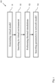
- Fig. 1
- shows a flow diagram of a method of determining thermal behavior of a power electronics device according to an embodiment;
- Fig. 2
- shows a schematic view of a power electronics device according to an embodiment;
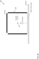
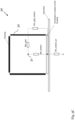
- Figs. 3A-C
- show virtual models of a power electronic device according to an embodiment; and
- Figs. 4A-B
- show circuit diagrams of network models according to an embodiment.
-
Fig. 1 shows a flow diagram of amethod 10 of determining thermal behavior of a power electronics device in an embodiment. - The
method 10 comprises the steps of: generating 11 a number of virtual models of the power electronics device, wherein each virtual model comprises: all heat-generating sources of the power electronics device represented by a single heat source (QSource), and some or all thermal connections of components of the power electronics device to each other and/or to a housing of the power electronics device represented by a number of thermal resistors which are connected to the single heat source; and performing 13 a number of thermal simulations with the virtual models to determine thermal parameters of the network model representing the power electronics device.. - The
method 10 may comprise the further step of inserting 14 the thermal parameters in the network model of the power electronics device. - The virtual models can be FEM or CFD models (i.e, models suitable for such simulations). Accordingly, the thermal simulations can be FEM or CFD simulations.
- The network model can be modelled by a circuit diagram which comprises the thermal resistors, the heat source and interconnections between the thermal resistors.
- The
method 10 can be a simulation method. The steps 11-14 of the method can be carried out by a computer or other processing unit. - For example, the thermal resistors in the virtual model and/or network model can represent some or all real thermal connections (e.g., conducting, radiating and/or convecting) from the components of the power electronics device to the surfaces of its housing. These thermal connections can also be represented by the specific arrangement of the individual thermal resistors.
- Each thermal parameter can be a respective value of one of the thermal resistors (e.g., in Kelvin / Watt). In particular, determining the thermal parameters via thermal simulations and inserting them in the network model can be referred to as parameterization of the model.
- For instance, when (virtually) designing a new power electronics device, a network model which represents the new device can be parameterized using the
method 10. - From the resulting fully parameterized network model, various thermal characteristics of the device can be derived. At the same time, the network model is "light weight" and does not require much computational power when being simulated (e.g., as part of a larger simulation environment).
- As shown in
Fig. 1 , themethod 10 can comprise the further optional step of: inserting 12 the virtual models in a virtual environment which comprises further heat dissipating and/or generating components, such as LED light source PCBs. The respective thermal simulations can then be performed with the virtual models in the virtual environment. - For instance, the power electronics device which is modelled by the virtual models and/or network model can be a LED driver. The virtual environment can comprise a model of a lighting infrastructure and/or an application environment of a luminaire which comprises the power electronics device.
- The thermal characteristics (e.g., flows) of the LED driver may change when the driver is arranged in another environment, especially a luminaire. To take this into account, the virtual model(s) and/or network model(s) can be integrated as a thermal sub-model(s) in the virtual environment, e.g. the thermal simulation of a luminaire or lighting infrastructure. Depending on the application scenario of the LED driver, the thermal characteristics may change, e.g., depending on the distance to the housing of the luminaire, it's geometry and mounting, and active or passive heat dissipation means of the luminaire etc. This can influence the results of the thermal simulations in the virtual environment (i.e., the determined thermal parameters).
- The resulting network model can then depict the thermal behavior of the power electronics device with sufficient precision in a situation where it is connected with other thermal models of structural elements (e.g., of a surrounding lighting-system, such as luminaire case, fixtures, LED-modules, structural elements, thermal heat sinks, etc.). Thus, it might not be necessary to perform highly detailed FEM or CFD simulations of the environment to assess its influence on the power electronics device.
- To arrive at the parameter values of the network model, a plurality of thermal simulations can be carried out with different virtual models. Thereby, each virtual model can be a specifically created FEM or CFD model. By performing a number of simulations with different models, the contribution of the individual network-components (e.g., the individual thermal resistors) can be isolated.
- This is possible, even if the elements, components and structures of the LED driver are randomly distributed in the space within the driver, and their relative contribution of heat transfer at their respective location is not known with spatial resolution. In the virtual models, all heat dissipating elements can be comprised into one virtual heat source, and all thermal pathways between the elements of the LED driver, and from those elements towards a housing structure and further into free air can be represented by a set of thermal resistances arranged in a dedicated fashion to depict direct and indirect interactions.
- For instance,
Fig. 2 shows a realistic representation of a power electronics device in the form of an LED driver in a thermal simulation. - Such a LED driver typically comprises various components which generate, dissipate and/or conduct heat when the driver is in operation. For instance, the components can comprise (elements of) a PCB, circuit elements or a control unit (e.g., an integrated circuit). In particular, heat generating sources of an LED driver can comprise an internal power converter or an integrated circuit.
-
Fig. 3A shows an example of a virtual model of this driver and its possible representation by thermal equivalent resistors Rth_left, Rth_top, Rth_right, Rth_bottom in a (simplified) network model, according to an embodiment. - The
virtual model 30 can be generated by dissecting the detailed representation into a number of thermal resistors Rth_left, Rth_top, Rth_right, Rth_bottom which are connected between asingle heat source 31 and thehousing 32 of the LED driver. Each thermal resistors inFig. 3A represents a thermal connection between theheat source 31 and one of the housing elements (left side, top side, right side, and bottom side). - To determine the thermal parameters, a number of consecutive thermal simulations can be performed with different virtual models. During each consecutive simulation, a different thermal parameter (or different parameters), for example a different value of a thermal resistor, can be determined.
- For example, a first thermal simulation can be performed with the virtual model shown in
Fig. 3B . - The virtual model shown in
Fig. 3B can be a nonrealistic representation of a generic LED driver for an FEM thermal simulation. In this model, all sides of the housing of the LED driver are intentionally thermally isolated from each other. This prevents any heat flow alongside the housing sides, thus enabling to evaluate only the direct heat-flow and thermal resistances of the independent pathways within the driver to each side of the driver housing. For example, when performing a thermal simulation with this virtual model, the thermal parameters Rth_right and Rth_bottom can be determined. -
Fig. 3C shows a further virtual model. In this virtual model some sides of the driver housing are thermally isolated from each other, while others are thermally connected. Together with calculations and results from the previous arrangement (Fig. 3B ), the values of the remaining thermal parameters (I.e., thermal resistances representing a heat-flow from one given driver-side to any connecting driver-side) in the model can be determined. - Further simulation can be carried out with more complex virtual models that e.g. consider a heat flow between all adjacent housing sides of the LED driver and/or that additionally consider heat dissipation from the housing into the surrounding air.
- While the
virtual models 30 shown inFigs. 3A-C are 2D models, also 3D models can be used. In this case, for example, the housing has six sides, and the model comprises at least six thermal resistors which represent a respective thermal connection between the heat source and each side of the housing. - The virtual models can comprise FEM or CFD models. For instance, FEM is a sub-type of a - usually complex - virtual model. The network models (which are partially also drawn in
Figs. 3A-C ), can be simplified models derived from any type of virtual model and/or can at least partially be comprised by a virtual model. - For instance, the virtual model in
Fig 3A is used as a starting point. A network model based onFig. 3A would be incomplete, as it does not fully depict the behavior of the virtual model. The virtual models inFig 3B and3C show generic variations: InFig. 3B the housing sides are deliberately isolated from each other (e.g., by some isolating "bars") to prevent heat-flow between the sides of thehousing 32. As a consequence, a direct heat-flow between thermal resistances (Rthright, Rthleft, Rthbott, Rthtop) can be determined. If one or more of the "isolating bars" are again removed (Fig 3C ) for variants of the virtual model, one dedicated thermal path between two selected housing sides is "re-opened", thus the related Rths between two re-connected sides can be determined specifically (inFig 3C that would be Rth_right_bottom) This procedure can be repeated for all connections to determine the remaining interconnection Rths, which can then be inserted in a full network model. -
Fig. 4A shows a network model of the power electronics device according to an embodiment. - The network model comprises a circuit diagram with individual thermal resistors representing the heat flow towards the housing sides and towards the air. However, the network model in
Fig. 4A neglects any heat flow along a housing of the power electronics device (as the model shown inFig. 3B ). - The thermal parameters (e.g., resistor values) which were determined with the simulations as shown in
Figs. 3A-C can be inserted in the network model ofFig. 4A . -
Fig. 4B shows a further network model of the power electronics device according to an embodiment. The network model shown inFig. 4B considers heat flow along the driver housing by means of additional interconnections and thermal resistors. For instance, the values of these thermal resistors can be determined via thermal simulations using appropriate virtual models of the power electronics device. - Although the invention has been illustrated and described with respect to one or more implementations, equivalent alternations and modifications will occur to those skilled in the art upon the reading of the understanding of the specification and the annexed drawings. In addition, while a particular feature of the invention may have been disclosed with respect to only of the several implementations, such features may be combined with one or more other features of the other implementations as may be desired and advantage for any given or particular application.
Claims (11)
- A method (10) of determining thermal behavior of a power electronics device, such as an LED driver, comprising:generating (11) a number of virtual models (30) of the power electronics device, wherein each virtual model (30) comprises:- a single heat source (31) which represents all heat-generating sources of the power electronics device, and- a number of thermal resistors which are connected to the heat source (31), and which represent thermal connections of components of the power electronics device to each other and/or to a housing (32) of the power electronics device;performing (13) a number of thermal simulations with the virtual models (30) to determine thermal parameters of a network model of the power electronics device.
- The method (10) of claim 1, further comprising:
inserting (14) the thermal parameters in the network model of the power electronics device. - The method (10) of claim 1,
wherein the thermal simulations comprise finite element simulations and/or computational fluid dynamics simulations. - The method (10) of claim any one of the preceding claims,
wherein at least one of the virtual models is configured to take a heat dissipation from the housing (32) into a surrounding medium into account. - The method (10) of any one of the preceding claims,
wherein at least one of the virtual models (30) is configured to neglect some or all indirect heat flows, such as heat flows between different sides of the housing (32), of the power electronics device. - The method (10) of any one of the preceding claims,
wherein at least one of the virtual models (30) is configured to take a heat flow on at least one side of the housing (32) of the power electronics device into account. - The method (10) of any one of the preceding claims,
wherein a number of consecutive thermal simulations is performed with different virtual models (30) of the number of virtual models. - The method (10) of claim 7,
wherein during each of the consecutive thermal simulations, a different thermal parameter, for example a different value of a thermal resistor, is determined. - The method (10) of any one of the preceding claims, further comprising:inserting (12) the virtual models (30) in a virtual environment which comprises further heat dissipating and/or generating components;wherein the number of thermal simulations is performed with the virtual environment.
- The method (10) of claim 9,
wherein the virtual environment comprises a thermal model of a lighting infrastructure and/or an application environment of a luminaire which comprises the power electronics device. - A computer program comprising instructions which, when the program is executed by a computer, cause the computer to perform the method according to any one of the preceding claims.
Priority Applications (1)
| Application Number | Priority Date | Filing Date | Title |
|---|---|---|---|
| PCT/EP2024/078280 WO2025078372A1 (en) | 2023-10-10 | 2024-10-08 | Method of determining thermal behavior of a power electronics device |
Applications Claiming Priority (1)
| Application Number | Priority Date | Filing Date | Title |
|---|---|---|---|
| AT501502023 | 2023-10-10 |
Publications (1)
| Publication Number | Publication Date |
|---|---|
| EP4538923A1 true EP4538923A1 (en) | 2025-04-16 |
Family
ID=89121805
Family Applications (1)
| Application Number | Title | Priority Date | Filing Date |
|---|---|---|---|
| EP23214504.5A Pending EP4538923A1 (en) | 2023-10-10 | 2023-12-06 | Method of determining thermal behavior of a power electronics device |
Country Status (1)
| Country | Link |
|---|---|
| EP (1) | EP4538923A1 (en) |
Citations (1)
| Publication number | Priority date | Publication date | Assignee | Title |
|---|---|---|---|---|
| CN108804777A (en) * | 2018-05-23 | 2018-11-13 | 东南大学 | A kind of LED illumination System life-span prediction method based on thermal coupling effect |
-
2023
- 2023-12-06 EP EP23214504.5A patent/EP4538923A1/en active Pending
Patent Citations (1)
| Publication number | Priority date | Publication date | Assignee | Title |
|---|---|---|---|---|
| CN108804777A (en) * | 2018-05-23 | 2018-11-13 | 东南大学 | A kind of LED illumination System life-span prediction method based on thermal coupling effect |
Non-Patent Citations (6)
| Title |
|---|
| FARKAS G ET AL: "LED Characterization Within the Delphi4LED Project", 2018 17TH IEEE INTERSOCIETY CONFERENCE ON THERMAL AND THERMOMECHANICAL PHENOMENA IN ELECTRONIC SYSTEMS (ITHERM), IEEE, 29 May 2018 (2018-05-29), pages 262 - 270, XP033377068, DOI: 10.1109/ITHERM.2018.8419602 * |
| MARTIN GENEVIEVE ET AL: "Luminaire Digital Design Flow with Multi-Domain Digital Twins of LEDs", ENERGIES, vol. 12, no. 12, 21 June 2019 (2019-06-21), pages 2389, XP055950563, DOI: 10.3390/en12122389 * |
| NIU HAO ET AL: "Multi-Time Scale Thermal Simulation Simulation-Assisted Lifetime Prediction of Power MOSFE T in LED Driver", 2019 INTERNATIONAL CONFERENCE ON QUALITY, RELIABILITY, RISK, MAINTENANCE, AND SAFETY ENGINEERING (QR2MSE), IEEE, 6 August 2019 (2019-08-06), pages 981 - 986, XP033733974, DOI: 10.1109/QR2MSE46217.2019.9021240 * |
| POPPE ANDRÁS ED - LABAT NATHALIE ET AL: "Simulation of LED based luminaires by using multi-domain compact models of LEDs and compact thermal models of their thermal environment", MICROELECTRONICS RELIABILITY : AN INTERNAT. JOURNAL & WORLD ABSTRACTING SERVICE, ELSEVIER SCIENCE LTD, GB, vol. 72, 6 April 2017 (2017-04-06), pages 65 - 74, XP029994684, ISSN: 0026-2714, DOI: 10.1016/J.MICROREL.2017.03.039 * |
| POPPE ANDRAS ET AL: "Creating multi-port thermal network models of LED luminaires for application in system level multi-domain simulation using spice-like solvers", 2015 31ST THERMAL MEASUREMENT, MODELING & MANAGEMENT SYMPOSIUM (SEMI-THERM), IEEE, 14 March 2016 (2016-03-14), pages 44 - 49, XP032894239, ISSN: 1065-2221, [retrieved on 20160422], DOI: 10.1109/SEMI-THERM.2016.7458444 * |
| YANG XIN ET AL: "Distributed Thermal Modeling for Power Devices and Modules With Equivalent Heat Flow Path Extraction", IEEE JOURNAL OF EMERGING AND SELECTED TOPICS IN POWER ELECTRONICS, IEEE, PISCATAWAY, NJ, USA, vol. 11, no. 6, 29 September 2023 (2023-09-29), pages 5863 - 5876, XP011954091, ISSN: 2168-6777, [retrieved on 20231002], DOI: 10.1109/JESTPE.2023.3321210 * |
Similar Documents
| Publication | Publication Date | Title |
|---|---|---|
| Evans et al. | Design tools for rapid multidomain virtual prototyping of power electronic systems | |
| TWI464603B (en) | Method and non-transitory computer readable medium thereof for thermal analysis modeling | |
| Bosch | Thermal compact models: An alternative approach | |
| Monier-Vinard et al. | Latest developments of compact thermal modeling of system-in-package devices by means of Genetic Algorithm | |
| US11481533B2 (en) | Systems and methods for designing a module semiconductor product | |
| Pandya et al. | A simplified method of generating thermal models for power MOSFETs | |
| Alexeev et al. | Requirements specification for multi-domain LED compact model development in Delphi4LED | |
| Poppe et al. | Creating multi-port thermal network models of LED luminaires for application in system level multi-domain simulation using Spice-like solvers | |
| WO2025078372A1 (en) | Method of determining thermal behavior of a power electronics device | |
| CN114787812A (en) | Method for measuring case for electronic component | |
| CN113361228A (en) | Simulation method of automobile machine cooling system, computer equipment and storage medium | |
| Monier-Vinard et al. | Delphi style compact modeling by means of genetic algorithms of system in Package devices using composite sub-compact thermal models dedicated to model order reduction | |
| Monier-Vinard et al. | Investigation on steady-state and transient boundary condition scenarios for optimizing the creation of multiport surrogate thermal models | |
| KR et al. | Testing of current carrying capacity of conducting tracks in high power flexible printed circuit boards | |
| Evstatiev et al. | Influence of the Constructive and Environmental Parameters on the Thermal Conditions of a LED Driver | |
| Nagy et al. | Simulation framework for multilevel power estimation and timing analysis of digital systems allowing the consideration of thermal effects | |
| Padmanabhan et al. | An integrated approach to developing thermal models for automotive electric drives | |
| Abali et al. | On the accuracy of reduced-order integrated circuit simulators for computing the heat production on electronic components | |
| Fodor et al. | Increasing Thermal Simulation Efficiency with 6SigmaET | |
| Petrosyants et al. | Simulation of Electrothermal Transient Responses in Power PCB Modules Using Comsol, Spice, and Asonika-TM | |
| Bailey et al. | Co-design, modelling and simulation challenges: from components to systems | |
| Hauck et al. | Electro-thermal Simulation of Interconnected Systems at Transient Operating Conditions | |
| Kammerer et al. | Multidomain Modeling for Reliability Evaluation of Devices and Microsystems Using Verilog-A | |
| JP2021170186A (en) | Thermal resistance estimation device, thermal resistance estimation program, data table creation method, and data structure | |
| Vakrilov et al. | Application of CFD modeling to solve problems in thermal design of LED applications in the initial project phase |
Legal Events
| Date | Code | Title | Description |
|---|---|---|---|
| PUAI | Public reference made under article 153(3) epc to a published international application that has entered the european phase |
Free format text: ORIGINAL CODE: 0009012 |
|
| STAA | Information on the status of an ep patent application or granted ep patent |
Free format text: STATUS: THE APPLICATION HAS BEEN PUBLISHED |
|
| AK | Designated contracting states |
Kind code of ref document: A1 Designated state(s): AL AT BE BG CH CY CZ DE DK EE ES FI FR GB GR HR HU IE IS IT LI LT LU LV MC ME MK MT NL NO PL PT RO RS SE SI SK SM TR |
|
| STAA | Information on the status of an ep patent application or granted ep patent |
Free format text: STATUS: REQUEST FOR EXAMINATION WAS MADE |
|
| 17P | Request for examination filed |
Effective date: 20250519 |