EP4538839A1 - Information processing device, controller display method and computer program - Google Patents
Information processing device, controller display method and computer program Download PDFInfo
- Publication number
- EP4538839A1 EP4538839A1 EP23819661.2A EP23819661A EP4538839A1 EP 4538839 A1 EP4538839 A1 EP 4538839A1 EP 23819661 A EP23819661 A EP 23819661A EP 4538839 A1 EP4538839 A1 EP 4538839A1
- Authority
- EP
- European Patent Office
- Prior art keywords
- input device
- controller
- captured image
- user
- section
- Prior art date
- Legal status (The legal status is an assumption and is not a legal conclusion. Google has not performed a legal analysis and makes no representation as to the accuracy of the status listed.)
- Pending
Links
Images




Classifications
-
- G—PHYSICS
- G06—COMPUTING OR CALCULATING; COUNTING
- G06F—ELECTRIC DIGITAL DATA PROCESSING
- G06F3/00—Input arrangements for transferring data to be processed into a form capable of being handled by the computer; Output arrangements for transferring data from processing unit to output unit, e.g. interface arrangements
- G06F3/01—Input arrangements or combined input and output arrangements for interaction between user and computer
- G06F3/048—Interaction techniques based on graphical user interfaces [GUI]
- G06F3/0484—Interaction techniques based on graphical user interfaces [GUI] for the control of specific functions or operations, e.g. selecting or manipulating an object, an image or a displayed text element, setting a parameter value or selecting a range
-
- G—PHYSICS
- G06—COMPUTING OR CALCULATING; COUNTING
- G06F—ELECTRIC DIGITAL DATA PROCESSING
- G06F3/00—Input arrangements for transferring data to be processed into a form capable of being handled by the computer; Output arrangements for transferring data from processing unit to output unit, e.g. interface arrangements
- G06F3/01—Input arrangements or combined input and output arrangements for interaction between user and computer
- G06F3/011—Arrangements for interaction with the human body, e.g. for user immersion in virtual reality
- G06F3/014—Hand-worn input/output arrangements, e.g. data gloves
-
- A—HUMAN NECESSITIES
- A63—SPORTS; GAMES; AMUSEMENTS
- A63F—CARD, BOARD, OR ROULETTE GAMES; INDOOR GAMES USING SMALL MOVING PLAYING BODIES; VIDEO GAMES; GAMES NOT OTHERWISE PROVIDED FOR
- A63F13/00—Video games, i.e. games using an electronically generated display having two or more dimensions
- A63F13/20—Input arrangements for video game devices
- A63F13/21—Input arrangements for video game devices characterised by their sensors, purposes or types
- A63F13/211—Input arrangements for video game devices characterised by their sensors, purposes or types using inertial sensors, e.g. accelerometers or gyroscopes
-
- A—HUMAN NECESSITIES
- A63—SPORTS; GAMES; AMUSEMENTS
- A63F—CARD, BOARD, OR ROULETTE GAMES; INDOOR GAMES USING SMALL MOVING PLAYING BODIES; VIDEO GAMES; GAMES NOT OTHERWISE PROVIDED FOR
- A63F13/00—Video games, i.e. games using an electronically generated display having two or more dimensions
- A63F13/20—Input arrangements for video game devices
- A63F13/21—Input arrangements for video game devices characterised by their sensors, purposes or types
- A63F13/212—Input arrangements for video game devices characterised by their sensors, purposes or types using sensors worn by the player, e.g. for measuring heart beat or leg activity
-
- A—HUMAN NECESSITIES
- A63—SPORTS; GAMES; AMUSEMENTS
- A63F—CARD, BOARD, OR ROULETTE GAMES; INDOOR GAMES USING SMALL MOVING PLAYING BODIES; VIDEO GAMES; GAMES NOT OTHERWISE PROVIDED FOR
- A63F13/00—Video games, i.e. games using an electronically generated display having two or more dimensions
- A63F13/20—Input arrangements for video game devices
- A63F13/21—Input arrangements for video game devices characterised by their sensors, purposes or types
- A63F13/213—Input arrangements for video game devices characterised by their sensors, purposes or types comprising photodetecting means, e.g. cameras, photodiodes or infrared cells
-
- A—HUMAN NECESSITIES
- A63—SPORTS; GAMES; AMUSEMENTS
- A63F—CARD, BOARD, OR ROULETTE GAMES; INDOOR GAMES USING SMALL MOVING PLAYING BODIES; VIDEO GAMES; GAMES NOT OTHERWISE PROVIDED FOR
- A63F13/00—Video games, i.e. games using an electronically generated display having two or more dimensions
- A63F13/40—Processing input control signals of video game devices, e.g. signals generated by the player or derived from the environment
- A63F13/42—Processing input control signals of video game devices, e.g. signals generated by the player or derived from the environment by mapping the input signals into game commands, e.g. mapping the displacement of a stylus on a touch screen to the steering angle of a virtual vehicle
- A63F13/428—Processing input control signals of video game devices, e.g. signals generated by the player or derived from the environment by mapping the input signals into game commands, e.g. mapping the displacement of a stylus on a touch screen to the steering angle of a virtual vehicle involving motion or position input signals, e.g. signals representing the rotation of an input controller or a player's arm motions sensed by accelerometers or gyroscopes
-
- A—HUMAN NECESSITIES
- A63—SPORTS; GAMES; AMUSEMENTS
- A63F—CARD, BOARD, OR ROULETTE GAMES; INDOOR GAMES USING SMALL MOVING PLAYING BODIES; VIDEO GAMES; GAMES NOT OTHERWISE PROVIDED FOR
- A63F13/00—Video games, i.e. games using an electronically generated display having two or more dimensions
- A63F13/50—Controlling the output signals based on the game progress
- A63F13/52—Controlling the output signals based on the game progress involving aspects of the displayed game scene
- A63F13/525—Changing parameters of virtual cameras
- A63F13/5255—Changing parameters of virtual cameras according to dedicated instructions from a player, e.g. using a secondary joystick to rotate the camera around a player's character
-
- A—HUMAN NECESSITIES
- A63—SPORTS; GAMES; AMUSEMENTS
- A63F—CARD, BOARD, OR ROULETTE GAMES; INDOOR GAMES USING SMALL MOVING PLAYING BODIES; VIDEO GAMES; GAMES NOT OTHERWISE PROVIDED FOR
- A63F13/00—Video games, i.e. games using an electronically generated display having two or more dimensions
- A63F13/50—Controlling the output signals based on the game progress
- A63F13/53—Controlling the output signals based on the game progress involving additional visual information provided to the game scene, e.g. by overlay to simulate a head-up display [HUD] or displaying a laser sight in a shooting game
-
- A—HUMAN NECESSITIES
- A63—SPORTS; GAMES; AMUSEMENTS
- A63F—CARD, BOARD, OR ROULETTE GAMES; INDOOR GAMES USING SMALL MOVING PLAYING BODIES; VIDEO GAMES; GAMES NOT OTHERWISE PROVIDED FOR
- A63F13/00—Video games, i.e. games using an electronically generated display having two or more dimensions
- A63F13/55—Controlling game characters or game objects based on the game progress
-
- G—PHYSICS
- G02—OPTICS
- G02B—OPTICAL ELEMENTS, SYSTEMS OR APPARATUS
- G02B27/00—Optical systems or apparatus not provided for by any of the groups G02B1/00 - G02B26/00, G02B30/00
- G02B27/01—Head-up displays
- G02B27/017—Head mounted
-
- G—PHYSICS
- G06—COMPUTING OR CALCULATING; COUNTING
- G06F—ELECTRIC DIGITAL DATA PROCESSING
- G06F3/00—Input arrangements for transferring data to be processed into a form capable of being handled by the computer; Output arrangements for transferring data from processing unit to output unit, e.g. interface arrangements
- G06F3/002—Specific input/output arrangements not covered by G06F3/01 - G06F3/16
- G06F3/005—Input arrangements through a video camera
-
- G—PHYSICS
- G06—COMPUTING OR CALCULATING; COUNTING
- G06F—ELECTRIC DIGITAL DATA PROCESSING
- G06F3/00—Input arrangements for transferring data to be processed into a form capable of being handled by the computer; Output arrangements for transferring data from processing unit to output unit, e.g. interface arrangements
- G06F3/01—Input arrangements or combined input and output arrangements for interaction between user and computer
-
- G—PHYSICS
- G06—COMPUTING OR CALCULATING; COUNTING
- G06F—ELECTRIC DIGITAL DATA PROCESSING
- G06F3/00—Input arrangements for transferring data to be processed into a form capable of being handled by the computer; Output arrangements for transferring data from processing unit to output unit, e.g. interface arrangements
- G06F3/01—Input arrangements or combined input and output arrangements for interaction between user and computer
- G06F3/011—Arrangements for interaction with the human body, e.g. for user immersion in virtual reality
-
- G—PHYSICS
- G06—COMPUTING OR CALCULATING; COUNTING
- G06F—ELECTRIC DIGITAL DATA PROCESSING
- G06F3/00—Input arrangements for transferring data to be processed into a form capable of being handled by the computer; Output arrangements for transferring data from processing unit to output unit, e.g. interface arrangements
- G06F3/01—Input arrangements or combined input and output arrangements for interaction between user and computer
- G06F3/017—Gesture based interaction, e.g. based on a set of recognized hand gestures
-
- G—PHYSICS
- G06—COMPUTING OR CALCULATING; COUNTING
- G06F—ELECTRIC DIGITAL DATA PROCESSING
- G06F3/00—Input arrangements for transferring data to be processed into a form capable of being handled by the computer; Output arrangements for transferring data from processing unit to output unit, e.g. interface arrangements
- G06F3/01—Input arrangements or combined input and output arrangements for interaction between user and computer
- G06F3/03—Arrangements for converting the position or the displacement of a member into a coded form
- G06F3/033—Pointing devices displaced or positioned by the user, e.g. mice, trackballs, pens or joysticks; Accessories therefor
- G06F3/0346—Pointing devices displaced or positioned by the user, e.g. mice, trackballs, pens or joysticks; Accessories therefor with detection of the device orientation or free movement in a three-dimensional [3D] space, e.g. 3D mice, 6-DOF [six degrees of freedom] pointers using gyroscopes, accelerometers or tilt-sensors
-
- G—PHYSICS
- G06—COMPUTING OR CALCULATING; COUNTING
- G06F—ELECTRIC DIGITAL DATA PROCESSING
- G06F3/00—Input arrangements for transferring data to be processed into a form capable of being handled by the computer; Output arrangements for transferring data from processing unit to output unit, e.g. interface arrangements
- G06F3/01—Input arrangements or combined input and output arrangements for interaction between user and computer
- G06F3/048—Interaction techniques based on graphical user interfaces [GUI]
- G06F3/0481—Interaction techniques based on graphical user interfaces [GUI] based on specific properties of the displayed interaction object or a metaphor-based environment, e.g. interaction with desktop elements like windows or icons, or assisted by a cursor's changing behaviour or appearance
-
- G—PHYSICS
- G06—COMPUTING OR CALCULATING; COUNTING
- G06F—ELECTRIC DIGITAL DATA PROCESSING
- G06F3/00—Input arrangements for transferring data to be processed into a form capable of being handled by the computer; Output arrangements for transferring data from processing unit to output unit, e.g. interface arrangements
- G06F3/01—Input arrangements or combined input and output arrangements for interaction between user and computer
- G06F3/048—Interaction techniques based on graphical user interfaces [GUI]
- G06F3/0481—Interaction techniques based on graphical user interfaces [GUI] based on specific properties of the displayed interaction object or a metaphor-based environment, e.g. interaction with desktop elements like windows or icons, or assisted by a cursor's changing behaviour or appearance
- G06F3/04815—Interaction with a metaphor-based environment or interaction object displayed as three-dimensional [3D], e.g. changing the user viewpoint with respect to the environment or object
-
- G—PHYSICS
- G06—COMPUTING OR CALCULATING; COUNTING
- G06T—IMAGE DATA PROCESSING OR GENERATION, IN GENERAL
- G06T11/00—Two-dimensional [2D] image generation
-
- G—PHYSICS
- G06—COMPUTING OR CALCULATING; COUNTING
- G06T—IMAGE DATA PROCESSING OR GENERATION, IN GENERAL
- G06T19/00—Manipulating three-dimensional [3D] models or images for computer graphics
- G06T19/006—Mixed reality
-
- G—PHYSICS
- G06—COMPUTING OR CALCULATING; COUNTING
- G06T—IMAGE DATA PROCESSING OR GENERATION, IN GENERAL
- G06T7/00—Image analysis
- G06T7/70—Determining position or orientation of objects or cameras
Definitions
- the present invention relates to an information processing device, a controller display method, and a computer program.
- An image display system has spread which enables a user wearing a head-mounted display to view a target space from a free viewpoint.
- electronic content for realizing virtual reality (VR) by setting a virtual three-dimensional space as a display target and displaying an image corresponding to a sight line direction of the user on the head-mounted display is known (the electronic content will hereinafter be referred to also as "VR content").
- VR content virtual reality
- the use of the head-mounted display can also enhance a sense of immersion in video and improve operability of an application such as a game.
- a walkthrough system has also been developed which enables the user wearing the head-mounted display to virtually walk around in a space displayed as the VR content by moving physically.
- video see-through has also been realized in which three-dimensional content is displayed so as to be superimposed on the video of a surrounding real world captured by a camera included in the head-mounted display.
- the user using the head-mounted display may put on the head-mounted display without holding a controller in a hand, and try to hold the controller in a hand after putting on the head-mounted display.
- the user can view the video of the surroundings captured by the camera of the head-mounted display, but may not know how to hold the controller until the user is accustomed to the shape of the controller.
- an information processing device includes a captured image obtaining section configured to obtain a captured image resulting from capturing a front of a user wearing a head-mounted display, an estimating section configured to estimate a position of a controller including a gripping portion to be gripped by the user on the basis of the captured image in which the controller appears, and a display control section configured to display the captured image resulting from capturing the front of the user on the head-mounted display.
- the display control section further displays a first object indicating a part to be gripped by the user together with the captured image on the basis of an estimation result of the position of the controller.
- Another aspect of the present invention is a controller display method.
- This method performed by a computer includes a step of obtaining a captured image resulting from capturing a front of a user wearing a head-mounted display, a step of estimating a position of a controller including a gripping portion to be gripped by the user on the basis of the captured image in which the controller appears, and a step of displaying the captured image resulting from capturing the front of the user on the head-mounted display.
- the displaying step further displays a first object indicating a part to be gripped by the user together with the captured image on the basis of an estimation result of the position of the controller.
- any combinations of the above constituent elements as well as modes obtained by converting expressions of the present invention between a system, a computer program, a recording medium having the computer program readably recorded thereon, a data structure, and the like are also effective as modes of the present invention.
- an information processing device game machine or the like
- a controller referred to also as an "input device” in an embodiment
- the head-mounted display can also be said to be a VR headset.
- the head-mounted display will hereinafter be referred to also as an "HMD.”
- the controller is set in a power-on state, or in other words, set in a state of being supplied with power from a power supply such as a battery.
- a user mounts the HMD on a head portion thereof without holding the controller in a hand, and performs various kinds of adjustments.
- the user holds the controller in a hand, and performs an operation related to the editing of a play area in which the user wearing the HMD can move.
- the user When the user is to hold the controller in a hand to edit the play area, the user can view the video of a surrounding real world captured by a camera of the HMD. However, it is not easy for an unaccustomed user to find the controller on the basis of the video captured by the camera of the HMD, and determine the attitude of the controller correctly and grip the controller correctly.
- the information processing system adds information assisting in correctly gripping the controller to the video captured by the camera of the HMD, and presents the resulting video to the user.
- information assisting in correctly gripping the controller an object indicating a part to be gripped is added in the vicinity of a gripping portion of the controller appearing in a captured image.
- the controller includes a curved portion for the user to insert a hand in addition to the gripping portion, and as the information assisting in correctly gripping the controller, an object indicating the part through which to insert a hand is added in the vicinity of the curved portion of the controller appearing in the captured image. The user wearing the HMD is thereby assisted in correctly gripping the controller.
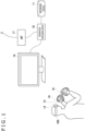
- FIG. 1 illustrates an example of a configuration of an information processing system 1 in an embodiment.
- the information processing system 1 includes an information processing device 10, a recording device 11, an HMD 100, an input device 16 held by the user and operated by fingers thereof, and an output device 15 that outputs an image and sound.
- the output device 15 may be a television set.
- the information processing device 10 is connected to an external network 2 such as the Internet via an access point (AP) 17.
- the AP 17 has functions of a wireless access point and a router.
- the information processing device 10 may be connected to the AP 17 by a cable, or may be connected to the AP 17 by a known wireless communication protocol.
- the recording device 11 records system software and applications such as game software.
- the information processing device 10 may download various applications such as the game software from a content server to the recording device 11 via the network 2.
- the information processing device 10 executes the various applications, and supplies the HMD 100 with image data and audio data on an application intended for output (which data can also be said to be the data on VR content).
- the information processing device 10 and the HMD 100 may be connected to each other by a known wireless communication protocol, and may be connected to each other by a cable.
- the HMD 100 is a display device that displays an image on a display panel that is located in front of eyes of the user when the user wears the HMD 100 on the head portion thereof.
- the HMD 100 individually and separately displays an image for the left eye on a display panel for the left eye and an image for the right eye on a display panel for the right eye. These images constitute parallax images as viewed from a left and a right viewpoint, and realize a stereoscopic view.
- the user views the display panel through optical lenses.
- the information processing device 10 therefore supplies the HMD 100 with parallax image data resulting from correction of optical distortion by the lenses.
- the output device 15 is not necessary for the user wearing the HMD 100. However, the preparation of the output device 15 enables another user to view the display image of the output device 15.
- the information processing device 10 may display the same image as the image viewed by the user wearing the HMD 100 on the output device 15. However, the information processing device 10 may display another image on the output device 15. For example, in a case where the user wearing the HMD 100 and another user plays a game together, a game image obtained from a character viewpoint of the other user may be displayed from the output device 15.
- the information processing device 10 and the input device 16 may be connected to each other by a known wireless communication protocol, and may be connected to each other by a cable.
- the input device 16 includes a plurality of operating members such as operating buttons. The user operates the operating members by fingers while gripping the input device 16.
- the input device 16 is used as a game controller when the information processing device 10 executes a game. For example, user operations related to the progress of the game are input to the operating members, and the input device 16 transmits operation information thereof to the information processing device 10 to make the user operations reflected in the game.
- the input device 16 may be a controller that communicates with the HMD 100 and controls the operation of the HMD 100.
- the input device 16 is provided with an inertial measurement device (IMU) including a triaxial acceleration sensor and a triaxial angular velocity sensor.
- IMU inertial measurement device
- the input device 16 transmits sensor data measured by the IMU to the information processing device 10 in a predetermined cycle (for example, 800 Hz).
- the game in the embodiment deals with not only the operation information on the operating members of the input device 16 but also the position, the speed, the attitude, and the like of the input device 16 as operation information, and reflects the operation information in the motion of a player character in a virtual three-dimensional space.
- the operation information on the operating members may be used as information for moving the player character
- the operation information such as the position, the speed, and the attitude of the input device 16 may be used as information for moving arms of the player character.
- the input device 16 In order to track the position and the attitude of the input device 16, the input device 16 is provided with a plurality of markers (light emitting units) that can be captured by imaging devices 14.
- the information processing device 10 has a function of analyzing an image obtained by capturing the input device 16 and estimating the position and the attitude of the input device 16 in a real space (which function will hereinafter be referred to also as a "first estimating function").
- the HMD 100 is mounted with a plurality of the imaging devices 14.
- the plurality of imaging devices 14 are attached in different attitudes to different positions of a front surface of the HMD 100 such that an entire capturing range obtained by adding together capturing ranges of the respective imaging devices 14 includes all of a field of view of the user.
- the imaging devices 14 each include an image sensor capable of obtaining images of the plurality of markers of the input device 16.
- the imaging devices 14 each include a visible light sensor used in an ordinary digital video camera, such as a CCD (Charge Coupled Device) sensor or a CMOS (Complementary Metal Oxide Semiconductor) sensor.
- the imaging devices 14 each include an invisible light sensor.
- the plurality of imaging devices 14 capture the front of the user in a predetermined period (for example, 120 frames/sec) in synchronized timing, and transmit the data on an image obtained by capturing the real space (which image will hereinafter be referred to also as a "captured image") to the information processing device 10.
- the captured image in the embodiment is an image obtained by capturing the real space in a direction of the front of the user wearing the HMD 100 (in a direction in which the face of the user is oriented).
- the information processing device 10 performs the first estimating function and thereby identifies the positions of a plurality of marker images of the input device 16 included in the captured image.
- the information processing device 10 may synthesize the plurality of captured images and identify the positions of the marker images because attachment positions and attachment attitudes of the imaging devices 14 are known.
- the three-dimensional shape of the input device 16 and the position coordinates of the plurality of markers arranged on the surface of the input device 16 are known.
- the information processing device 10 estimates the position and the attitude in the real space of the input device 16 on the basis of the position coordinates of the plurality of marker images in the captured image.
- the position of the input device 16 may be estimated as a coordinate value in world coordinates in a three-dimensional space having a reference position as an origin.
- the reference position may be position coordinates (latitude, longitude, and altitude (height above the sea level)) set before a start of the game.
- the attitude of the input device 16 may be expressed by an inclination or an angle on each of three axes with respect to a predetermined reference attitude.
- the information processing device 10 in the embodiment has a function of analyzing the sensor data transmitted from the input device 16 and estimating the position and the attitude of the input device 16 in the real space (which function will hereinafter be referred to also as a "second estimating function").
- the information processing device 10 derives the position and the attitude of the input device 16 by using an estimation result of the first estimating function and an estimation result of the second estimating function.
- the information processing device 10 in the embodiment integrates the estimation result of the first estimating function and the estimation result of the second estimating function by utilizing a state estimating technology using a Kalman filter, and thereby estimates the state of the input device 16 at a present time with high accuracy.
- FIG. 2 illustrates an example of an external shape of the HMD 100.
- the HMD 100 includes an output mechanism unit 102 and a mounting mechanism unit 104.
- the mounting mechanism unit 104 includes a mounting band 106 that encircles the head portion and fixes the HMD 100 to the head portion when the user puts on the mounting band 106.
- the mounting band 106 is of a material or a structure that allows a length adjustment thereof according to the circumference of the head of the user.
- the output mechanism unit 102 includes a casing 108 having such a shape as to cover the left and right eyes in a state in which the user wears the HMD 100, and internally includes the display panel that squarely faces the eyes at a time of the wearing.
- the display panel may be a liquid crystal panel, an organic EL panel, or the like.
- Further included in the casing 108 is a pair of left and right optical lenses that are located between the display panel and the eyes of the user and that expand the viewing angle of the user.
- the HMD 100 may further include speakers or earphones at positions corresponding to ears of the user, or may be configured to be connected with external headphones.
- An external surface on the front side of the casing 108 is provided with imaging devices 14a, 14b, 14c, and 14d as the plurality of imaging devices 14.
- the imaging device 14a is attached to an upper right corner of the external surface on the front side such that a camera optical axis thereof is directed rightward and obliquely upward
- the imaging device 14b is attached to an upper left corner of the external surface on the front side such that a camera optical axis thereof is directed leftward and obliquely upward
- the imaging device 14c is attached to a lower right corner of the external surface on the front side such that a camera optical axis thereof is directed rightward and obliquely downward
- the imaging device 14d is attached to a lower left corner of the external surface on the front side such that a camera optical axis thereof is directed leftward and obliquely downward.
- an entire capturing range obtained by adding together the respective capturing ranges of the plurality of imaging devices 14 includes all of the field of view of the user.
- the field of view of the user may be a field of view of the user in a three-dimensional virtual space.
- the HMD 100 transmits sensor data detected by the IMU and image data captured by the imaging device 14 to the information processing device 10, and receives game image data and game sound data generated in the information processing device 10.
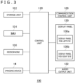
- FIG. 3 illustrates a functional block of the HMD 100.
- a control unit 120 is a main processor that processes various kinds of data such as image data, audio data, and sensor data as well as instructions, and performs output.
- the control unit 120 may include a CPU (Central Processing Unit) and a GPU (Graphics Processing Unit).
- a storage unit 122 temporarily stores the data and the instructions processed by the control unit 120 and the like.
- An IMU 124 obtains the sensor data related to motion of the HMD 100.
- the IMU 124 may include at least a triaxial acceleration sensor and a triaxial angular velocity sensor.
- the IMU 124 detects the values (sensor data) of respective axial components in a predetermined cycle (for example, 800 Hz).
- a communication control unit 128 transmits data output from the control unit 120 to the external information processing device 10 by wired or wireless communication via a network adapter or an antenna. In addition, the communication control unit 128 receives data from the information processing device 10, and outputs the data to the control unit 120.
- control unit 120 When the control unit 120 receives the game image data and the game sound data from the information processing device 10, the control unit 120 supplies the game image data to a display panel 130 to make a display thereof and supplies the game sound data to an audio output unit 132 to perform an audio output thereof.
- the display panel 130 includes a display panel 130a for the left eye and a display panel 130b for the right eye. A pair of parallax images are displayed on the respective display panels.
- the control unit 120 causes sensor data from the IMU 124, audio data from a microphone 126, and captured image data from the imaging devices 14 to be transmitted from the communication control unit 128 to the information processing device 10.
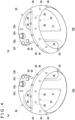
- FIG. 4(a) illustrates the shape of an input device 16a for a left hand.
- the input device 16a for the left hand includes a case body 20, a plurality of operating members 22a, 22b, 22c, and 22d (hereinafter referred to as "operating members 22" in a case where the plurality of operating members 22a, 22b, 22c, and 22d are not particularly distinguished from each other) operated by the user, and a plurality of markers 30 that emit light to the outside of the case body 20.
- the markers 30 may have an emitting unit having a circular cross section.
- the operating members 22 may include an analog stick operated by tilting, a depression type button, and the like.
- the case body 20 includes a gripping portion 21 and a curved portion 23 that couples a case body head portion and a case body bottom portion to each other.
- the user puts the left hand through the curved portion 23, and grips the gripping portion 21.
- the user operates the operating members 22a, 22b, 22c, and 22d by using a thumb of the left hand in a state in which the user grips the gripping portion 21.
- FIG. 4(b) illustrates the shape of an input device 16b for a right hand.
- the input device 16b for the right hand includes a case body 20, a plurality of operating members 22e, 22f, 22g, and 22h (hereinafter referred to as "operating members 22" in a case where the plurality of operating members 22e, 22f, 22g, and 22h are not particularly distinguished from each other) operated by the user, and a plurality of markers 30 that emit light to the outside of the case body 20.
- the operating members 22 may include an analog stick operated by tilting, a depression type button, and the like.
- the case body 20 includes a gripping portion 21 and a curved portion 23 that couples a case body head portion and a case body bottom portion to each other.
- the user puts the right hand through the curved portion 23, and grips the gripping portion 21.
- the user operates the operating members 22e, 22f, 22g, and 22h by using a thumb of the right hand in a state in which the user grips the gripping portion 21.
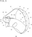
- FIG. 5 illustrates the shape of the input device 16b for the right hand.
- the input device 16b includes operating members 22i and 22j in addition to the operating members 22e, 22f, 22g, and 22h illustrated in FIG. 4(b) .
- the user operates the operating member 22i by using an index finger of the right hand, and operates the operating member 22j by using a middle finger thereof.
- the input device 16 in the embodiment is a controller including the gripping portion 21 to be gripped by the user after the user inserts a hand through the curved portion 23.
- Operating members 22 provided to the input device 16 may have a touch sensing function that recognizes a finger on the basis of a mere touch thereof without pressing.
- the operating members 22f, 22g, and 22j may have a capacitive type touch sensor.
- a touch sensor may be included in another operating member 22, a touch sensor is preferably included in an operating member 22 such that the touch sensor does not come into contact with a mounting surface such as a table when the input device 16 is placed on the mounting surface.
- the markers 30 are a light emitting unit that emits light to the outside of the case body 20.
- the markers 30 include, in the surface of the case body 20, a resin portion that diffuses and emits light from a light source such as an LED (Light Emitting Diode) element to the outside.
- the markers 30 are captured by the imaging devices 14, and are used for tracking processing of the input device 16.
- the information processing device 10 uses the captured image captured by the imaging devices 14 for the tracking processing of the input device 16 and SLAM (Simultaneous Localization and Mapping) processing of the HMD 100.
- SLAM Simultaneous Localization and Mapping
- images captured by the imaging devices 14 at 120 frames/sec gray scale images captured at 60 frames/sec may be used for the tracking processing of the input device 16, and other full color images captured at 60 frames/sec may be used for processing of simultaneously performing self-position estimation and environmental map generation of the HMD 100.
- FIG. 6 illustrates an example of a part of an image obtained by capturing the input device 16.
- This image is an image obtained by capturing the input device 16b held by the right hand, and includes images of the plurality of markers 30 that emit light.
- the communication control unit 128 in the HMD 100 transmits the image data captured by the imaging devices 14 to the information processing device 10 in real time.
- FIG. 7 is a block diagram illustrating functional blocks of the input device 16.
- a control unit 50 receives operation information input to the operating members 22.
- the control unit 50 receives sensor data detected by an IMU 32 and sensor data detected by touch sensors 24.
- the touch sensors 24 are attached to at least some of the plurality of operating members 22, and sense states in which fingers of the user are in contact with the operating members 22.
- the IMU 32 obtains the sensor data related to motion of the input device 16.
- the IMU 32 includes at least an acceleration sensor 34 that detects triaxial acceleration data and an angular velocity sensor 36 that detects triaxial angular velocity data.
- the acceleration sensor 34 and the angular velocity sensor 36 detect the values (sensor data) of respective axial components in a predetermined cycle (for example, 800 Hz).
- the control unit 50 supplies the received operation information and the received sensor data to a communication control unit 54.
- the communication control unit 54 transmits the operation information and the sensor data to the information processing device 10 by wired or wireless communication via a network adapter or an antenna.
- the input device 16 includes a plurality of light sources 58 for lighting the plurality of markers 30.
- the light sources 58 may be an LED element that emits light in a predetermined color.
- the control unit 50 makes the light sources 58 emit light and thereby lights the markers 30 on the basis of the light emission instruction.
- one light source 58 is provided for one marker 30 in the example illustrated in FIG. 7
- one light source 58 may light a plurality of markers 30.
- FIG. 8 is a block diagram illustrating functional blocks of the information processing device 10.
- the information processing device 10 includes a processing section 200 and a communicating section 202.
- the processing section 200 includes an obtaining section 210, an application executing section 220, an image signal processing section 222, a marker information retaining section 224, a state retaining section 226, an estimation processing section 230, an image signal processing section 268, a SLAM processing section 270, an image generating section 272, and an image output section 274.
- the obtaining section 210 includes a captured image obtaining section 212, a sensor data obtaining section 214, and an operation information obtaining section 216.
- the estimation processing section 230 includes a first estimation processing section 240, a second estimation processing section 250, a third estimation processing section 260, and a stillness determining section 262.
- the communicating section 202 communicates with an external device according to a predetermined communication protocol.
- the external device includes the HMD 100, the output device 15, the input device 16, a server not illustrated, and another information processing device.
- the communicating section 202 receives the operation information on the operating members 22 and the sensor data transmitted from the input device 16, and supplies the operation information and the sensor data to the obtaining section 210.
- the communicating section 202 receives the captured image data and the sensor data transmitted from the HMD 100, and supplies the captured image data and the sensor data to the obtaining section 210.
- the information processing device 10 includes a computer.
- the computer implements the various functions illustrated in FIG. 8 by executing a program.
- the computer includes, as hardware, a memory into which to load the program, one or more processors (a CPU, a GPU, and the like) for executing the loaded program, an auxiliary storage device, another LSI, and the like.
- the processor may include a plurality of electronic circuits including a semiconductor integrated circuit or an LSI.
- the plurality of electronic circuits may be mounted on one chip, or may be mounted on a plurality of chips.
- the functional blocks illustrated in FIG. 8 are implemented by cooperation between hardware and software. Hence, it is to be understood by those skilled in the art that these functional blocks can be implemented in various forms by only hardware, only software, or combinations of hardware and software.
- the captured image obtaining section 212 obtains the full color images for the SLAM processing of the HMD 100, and supplies the full color images to the image signal processing section 268.
- the image signal processing section 268 subjects the image data to image signal processing such as noise reduction and optical correction (shading correction), and supplies the image data resulting from the image signal processing to the SLAM processing section 270.
- the sensor data obtaining section 214 obtains the sensor data transmitted from the HMD 100, and supplies the sensor data to the SLAM processing section 270.
- the SLAM processing section 270 simultaneously performs self-position estimation and environmental map generation of the HMD 100 on the basis of the image data supplied from the captured image obtaining section 212 and the sensor data supplied from the sensor data obtaining section 214.
- the captured image obtaining section 212 obtains the gray scale images for the tracking processing of the input device 16, and supplies the gray scale images to the image signal processing section 222.
- the image signal processing section 222 subjects the image data to image signal processing such as noise reduction and optical correction (shading correction), and supplies the image data resulting from the image signal processing to the first estimation processing section 240.
- the first estimation processing section 240 includes a marker image coordinate identifying section 242, a position and attitude deriving section 244, and a noise deriving section 248.
- the first estimation processing section 240 implements the first estimating function of estimating the position and the attitude of the input device 16 on the basis of the image obtained by capturing the input device 16.
- the first estimation processing section 240 extracts marker images obtained by capturing the plurality of markers 30 of the input device 16 from the captured image, and estimates the position and the attitude of the input device 16 from an arrangement of a plurality of the extracted marker images.
- the first estimation processing section 240 outputs the estimated position and attitude of the input device 16 to the third estimation processing section 260 together with the variance of noise (error) thereof.
- the sensor data obtaining section 214 obtains the sensor data transmitted from the input device 16, and supplies the sensor data to the second estimation processing section 250.
- the second estimation processing section 250 implements the second estimating function of estimating the position and the attitude of the input device 16 on the basis of the sensor data indicating the acceleration and angular velocity of the input device 16.
- the second estimating function is a function of performing a state predicting step in a Kalman filter.
- the second estimation processing section 250 estimates a state vector at this time by adding a state vector change amount obtained by integral operation on the supplied sensor data to a state vector (position, speed, and attitude) at a previous time.
- the second estimation processing section 250 outputs the estimated state vector to the third estimation processing section 260 together with the variance of noise thereof.
- the change amount obtained by the integral operation accumulates noise over time.
- the state vector (position, speed, and attitude) estimated by the second estimation processing section 250 tends to deviate from an actual state vector (position, speed, and attitude).
- the third estimation processing section 260 derives the position and the attitude of the input device 16 with high accuracy from the position and attitude of the input device 16 estimated by the first estimation processing section 240 and the state vector (position, speed, and attitude) of the input device 16 estimated by the second estimation processing section 250.
- the third estimation processing section 260 may perform a filtering step (correcting step) of a UKF (unscented Kalman Filter).
- the third estimation processing section 260 obtains the state vector estimated by the second estimation processing section 250 as a "prior estimated value,” obtains the position and the attitude estimated by the first estimation processing section 240 as an "observed value,” calculates a Kalman gain, and obtains an "posterior estimated value” resulting from correcting the "prior estimated value” by using the Kalman gain.
- the “posterior estimated value” represents the position and attitude of the input device 16 with high accuracy.
- the “posterior estimated value” is provided to the application executing section 220, and is recorded in the state retaining section 226 to be used for the estimation of the state vector at a next time in the second estimation processing section 250.
- a method of increasing accuracy by integrating results of analysis using a plurality of sensors such as the imaging devices 14 and the IMU 32 is known as sensor fusion.
- the sensor fusion times at which data is obtained by the respective sensors need to be expressed on a common time axis.
- the imaging cycle of the imaging devices 14 and the sampling cycle of the IMU 32 are different from each other and are asynchronous with each other.
- the third estimation processing section 260 can estimate the position and the attitude of the input device 16 with high accuracy.
- FIG. 9 is a flowchart illustrating position and attitude estimation processing by the first estimation processing section 240.
- the captured image obtaining section 212 obtains the image data resulting from capturing the input device 16 (S10) and supplies the image data to the image signal processing section 222.
- the image signal processing section 222 subjects the image data to image signal processing such as noise reduction and optical correction (S12) and supplies the image data resulting from the image signal processing to the marker image coordinate identifying section 242.
- the marker image coordinate identifying section 242 identifies representative coordinates of the plurality of marker images included in the captured image (S14). In a case where the luminance of each pixel of a gray scale image is represented by 8 bits, and assumes a luminance value of 0 to 255, the marker images are captured as images having high luminance, as illustrated in FIG. 6 .
- the marker image coordinate identifying section 242 may identify a region of consecutive pixels having luminance values equal to or higher than a predetermined value (for example, a luminance value of 128) from the captured image, calculate gravity center coordinates of the consecutive pixel region, and thereby identify the representative coordinates of a marker image.
- a predetermined value for example, a luminance value of 128
- the captured image includes not only the marker images but also an image of a lighting device such as an electric light. Accordingly, the marker image coordinate identifying section 242 investigates whether the consecutive pixel region having the luminance values equal to or higher than the predetermined value corresponds to a marker image by checking the consecutive pixel region against a few predetermined criteria. For example, in a case where the consecutive pixel region is too large, or in a case where the consecutive pixel region has an elongated shape, it is certain that the consecutive pixel region does not correspond to a marker image, and therefore, the marker image coordinate identifying section 242 may determine that such a consecutive pixel region is not a marker image.
- the marker image coordinate identifying section 242 calculates the gravity center coordinates of a consecutive pixel region satisfying the predetermined criteria, identifies the gravity center coordinates as the representative coordinates (marker image coordinates) of a marker image, and stores the identified representative coordinates in a memory (not illustrated).
- the marker information retaining section 224 retains three-dimensional coordinates of each marker in a three-dimensional model of the input device 16 in the reference position and the reference attitude.
- a method of solving a PNP (Perspective n-Point) problem is known as a method for estimating the position and the attitude of an imaging device that captures an object whose three-dimensional shape and size are known from a captured image of the object.
- the position and attitude deriving section 244 reads the coordinates of N (N is an integer of 3 or more) marker images from a memory (not illustrated), and estimates the position and the attitude of the input device 16 from the read coordinates of the N marker images and the three-dimensional coordinates of N markers in the three-dimensional model of the input device 16.
- the position and attitude deriving section 244 estimates the position and the attitude of the imaging device 14 by using the following (Equation 1), and derives the position and attitude in the three-dimensional space of the input device 16 on the basis of a result of the estimation. [Math.
- (u, v) is marker image coordinates in the captured image
- (X, Y, Z) is position coordinates in the three-dimensional space of the markers 30 when the three-dimensional model of the input device 16 is in the reference position and the reference attitude.
- the three-dimensional model is a model that has perfectly the same shape and size as the input device 16 and has markers arranged at the same positions.
- the marker information retaining section 224 retains the three-dimensional coordinates of each marker in the three-dimensional model in the reference position and the reference attitude.
- the position and attitude deriving section 244 obtains (X, Y, Z) by reading the three-dimensional coordinates of each marker from the marker information retaining section 224.
- (f x , f y ) is the focal length of the imaging device 14, and (c x , c y ) is an image principal point. Both are internal parameters of the imaging device 14.
- a matrix having r 11 to r 33 and t 1 to t 3 as elements is a rotation and translation matrix.
- (Equation 1) (u, v), (f x , f y ), (c x , c y ), and (X, Y, Z) are known.
- the position and attitude deriving section 244 solves the equation for the N markers 30, and thereby obtains a rotation and translation matrix common to these markers.
- the processing of estimating the position and the attitude of the input device 16 is performed by solving the P3P problem.
- the position and attitude deriving section 244 extracts the coordinates of freely selected three marker images from among the coordinates of the plurality of marker images identified by the marker image coordinate identifying section 242.
- the position and attitude deriving section 244 reads the three-dimensional coordinates of the markers in the three-dimensional model from the marker information retaining section 224, and solves the P3P problem by using (Equation 1).
- the position and attitude deriving section 244 identifies a rotation and translation matrix common to the coordinates of the three extracted marker images
- the position and attitude deriving section 244 calculates a reprojection error by using the marker image coordinates of the input device 16 other than the coordinates of the three extracted marker images.
- the position and attitude deriving section 244 extracts a predetermined number of combinations of the coordinates of three marker images.
- the position and attitude deriving section 244 identifies a rotation and translation matrix for each of the combinations of the coordinates of the three extracted marker images, and calculates a reprojection error for each. Then, the position and attitude deriving section 244 identifies a rotation and translation matrix providing a minimum reprojection error from among a predetermined number of reprojection errors, and derives the position and the attitude of the input device 16 (S16).
- the noise deriving section 248 derives the variance of noise (error) of each of the estimated position and attitude (S18).
- the variance value of the noise corresponds to a degree of reliability of the estimated position and attitude. When the degree of reliability is high, the variance value is small. When the degree of reliability is low, the variance value is large.
- the noise deriving section 248 may derive the variance of the noise on the basis of distances between the imaging devices 14 and the input device 16 and the positions of the marker images in an angle of view.
- the noise deriving section 248 may set the variance of the noise of each of the estimated position and the estimated attitude to a small fixed value.
- the noise deriving section 248 may set the variance of the position noise during the tracking processing to "0.5 mm" as a fixed value, and supply the set variance to the third estimation processing section 260.
- the first estimation processing section 240 may output the variances of the position noise and the attitude noise to the third estimation processing section 260 together with information regarding the estimated position and attitude.
- the noise variances may be output to the third estimation processing section 260 once at a time of a start of the tracking processing, and the third estimation processing section 260 may store and use the noise variances.
- the position and attitude estimation processing of the first estimation processing section 240 is performed in an imaging cycle of the images for the tracking of the input device 16 (60 frames/sec) (N in S20).
- N in S20 the position and attitude estimation processing of the first estimation processing section 240 is ended (Y in S20).
- FIG. 10 illustrates an internal configuration of the estimation processing section 230.
- the first estimation processing section 240 outputs the estimated position and attitude as an "observed value n k " and the variances of the position noise and the attitude noise as "observation noise R k " to the third estimation processing section 260.
- the second estimation processing section 250 reads a "state vector m k-1
- the state variable m in the embodiment includes the position, the speed, and the attitude of the input device 16, and may further include an acceleration bias and an angular velocity bias.
- the second estimation processing section 250 calculates the variance of acceleration noise and the variance of angular velocity noise from the acceleration a k and the angular velocity ⁇ k and fixed noise parameters (including an axis shift, a scale shift, a value shift, and a bias shift), and inputs the variances as "process noise Q k " to the predicting section.
- the predicting section performs an integral operation on each of the acceleration a k and the angular velocity ⁇ k , and performs an operation of calculating change amounts (that is, a position change amount, a speed change amount, and an attitude change amount) from the "state vector m k-1
- the predicting section calculates the speed change amount by integrating the acceleration a k , calculates the position change amount by integrating a speed estimated by using the speed change amount, and calculates the attitude change amount by integrating the angular velocity ⁇ k .
- the predicting section outputs the "state vector m k
- the third estimation processing section 260 obtains the "observed value n k " and the "observation noise R k " from the first estimation processing section 240, obtains the "state vector m k
- the third estimation processing section 260 corrects the "state vector m k
- the estimation processing of the first estimation processing section 240 is performed in a cycle of 60 Hz, while the estimation processing of the second estimation processing section 250 is performed in a cycle of 800 Hz. Therefore, during a period from the output of the observed value by the first estimation processing section 240 to the output of a next observed value, the second estimation processing section 250 sequentially updates the state vector. During this period, the state vector is not corrected.
- the estimation processing section 230 in the embodiment performs a correcting step with the state at time k-1 immediately before the observation time k as a reference, that is, uses the observed value to correct the state in the past.
- the estimation processing section 230 estimates the position and attitude of the input device 16 with high accuracy while the tracking processing of the input device 16 is performed. However, when the markers 30 of the input device 16 are not captured by the imaging device 14, the first estimation processing section 240 cannot perform the position and attitude estimation processing illustrated in FIG. 9 .
- the estimation processing section 230 estimates the position of the input device 16, or in other words, continues the tracking of the input device 16 on the basis of the sensor data on the HMD 100 and the sensor data on the input device 16. For example, in a case of determining on the basis of the sensor data on the HMD 100 that the HMD 100 has moved in a right direction after the input device 16 goes outside the angle of view of the imaging devices 14, the estimation processing section 230 may move the estimated position of the input device 16 in a left direction from a previous position thereof by an amount corresponding to the movement of the HMD 100 in the right direction.
- the estimation processing section 230 ends the processing of estimating the position of the input device 16 in a case where a predetermined tracking ending condition (for example, the passage of a predetermined time, a large movement of the HMD 100, or the like) is satisfied under conditions where the markers 30 of the input device 16 do not appear in the captured image.
- a predetermined tracking ending condition for example, the passage of a predetermined time, a large movement of the HMD 100, or the like
- the stillness determining section 262 determines whether or not the input device 16 is still on the basis of the sensor data indicating the acceleration of the input device 16, the sensor data being obtained by the sensor data obtaining section 214.
- the stillness determining section 262 calculates the slope of the acceleration from time series data on the acceleration of the input device 16, and determines whether or not the input device 16 is still on the basis of the calculated slope.
- the stillness determining section 262 in the embodiment obtains a regression line by applying a least-square method to 100 acceleration values from the present time t to a past time (t-99), and identifies the slope of the regression line.
- the number of samples at a time of calculating the slope may be other than 100.
- the stillness determining section 262 may calculate the slope in a sampling cycle of the sensor data, and thereby determine at all times whether or not the input device 16 is still.
- the stillness determining section 262 determines that the input device 16 is moving when the absolute value of the calculated slope is equal to or more than a predetermined threshold value Sth. The stillness determining section 262 determines that the input device 16 is still when the absolute value of the calculated slope is less than the threshold value Sth.
- the stillness determining section 264 may determine that the input device 16 is still when the absolute value of the calculated slope is consecutively less than the threshold value Sth a predetermined number of times (N3 times), and after determining that the input device 16 is still, the stillness determining section 264 may determine that the input device 16 is moving when the absolute value of the calculated slope is consecutively equal to or more than the threshold value Sth a predetermined number of times (N4 times).
- N3 and N4 may be a same number of times and may be different numbers of times.
- the stillness determining section 262 may determine whether or not the input device 16 is still on the basis of the captured image in which the input device 16 appears, the captured image being obtained by the captured image obtaining section 212. As another modification, the stillness determining section 262 may determine whether or not the input device 16 is still on the basis of time series changes in the position of the input device 16 estimated by any one of the first estimation processing section 240, the second estimation processing section 250, and the third estimation processing section 260.
- the captured image obtaining section 212 further provides the captured image data transmitted from the HMD 100 to the application executing section 220 and the image generating section 272.
- the sensor data obtaining section 214 further provides the sensor data transmitted from the HMD 100 to the application executing section 220 and the image generating section 272.
- the sensor data obtaining section 214 further provides the sensor data transmitted from the input device 16 to the application executing section 220 and the image generating section 272.
- the operation information obtaining section 216 obtains the operation information indicating user operation input to the input device 16, the operation information being transmitted from the input device 16.
- the operation information obtaining section 216 provides the obtained operation information to the application executing section 220.
- the application executing section 220 executes various kinds of applications on the basis of the operation information input from the operation information obtaining section 216, the sensor data input from the sensor data obtaining section 214, the position and attitude information of the input device 16 estimated by the estimation processing section 230 (for example, the third estimation processing section 260), and the like.
- the application executing section 220 may make a VR game progress by executing a computer program that implements various kinds of processing related to the VR game.
- the application executing section 220 executes an initial setting application of the HMD 100.
- the image generating section 272 and the image output section 274 function as a display control section 276 that controls the display of electronic content on a display unit.
- the display unit includes at least the display panel 130 of the HMD 100, and may further include the display of the output device 15.
- the display control section 276 displays a camera AR video to be described later on the display panel 130 of the HMD 100 during the execution of the initial setting application of the HMD 100.
- the image generating section 272 generates image data for display (for example, image data on VR content) to be displayed on the HMD 100 on the basis of the captured image data input from the captured image obtaining section 212, a result of execution of an application by the application executing section 220, and the like.
- the image output section 274 transmits the image data for display generated by the image generating section 272 to the HMD 100 to display the image data on the display panel 130 of the HMD 100.
- the image generating section 272 generates an image of the initial setting application of the HMD 100 on the basis of a result of execution of the initial setting application of the HMD 100 by the application executing section 220.
- the image of the initial setting application of the HMD 100 includes the captured image captured by the imaging devices 14 of the HMD 100, the captured image being obtained by capturing the real space in the front direction of the user wearing the HMD 100.
- the image of the initial setting application of the HMD 100 includes an augmented reality (AR) video (hereinafter referred to also as a "camera AR video”) on the basis of a video in which the real space in the front direction of the user wearing the HMD 100 appears.
- the image output section 274 displays the camera AR video generated by the image generating section 272 on the display panel 130 of the HMD 100.
- the camera AR video can include an image of a virtual object (hereinafter referred to also as a "guide object") that assists in correctly gripping the input device 16.
- the guide object includes an approximate position guide and an insertion position guide to be described later.
- the image generating section 272 respectively and individually manages the state of the input device 16a and the state of the input device 16b (position and attitude or the like), and respectively and individually determines a guide object to be added to the input device 16a and a guide object to be added to the input device 16b in the camera AR video.
- FIG. 11 illustrates an example of transitions of guide display in the camera AR video.
- the image generating section 272 sets the guide display for the input device 16 in a first mode, in a case where the estimation processing section 230 cannot track the position (for example, a coordinate value in a world coordinate system) of the input device 16.
- the first mode suppresses the display of the guide object added to the video of the input device 16, or in other words, sets the guide object in a non-display state.
- the image generating section 272 determines whether or not the input device 16 appears in the captured image captured by the imaging devices 14, that is, whether or not the input device 16 is in the field of view of the user. In addition, the image generating section 272 derives a distance between the HMD 100 and the input device 16 on the basis of the estimated position of the input device 16, and further determines whether or not the distance is equal to or less than a predetermined threshold value.
- This threshold value in the embodiment is 1.3 meters. However, an appropriate threshold value may be determined on the basis of the knowledge of a developer, an experiment using the information processing system 1, or the like.
- the image generating section 272 sets the guide display for the input device 16 in a second mode when the input device 16 does not appear in the captured image captured by the imaging devices 14 or the distance between the HMD 100 and the input device 16 exceeds the above-described threshold value in a case where the position of the input device 16 can be tracked.
- the second mode disposes the approximate position guide as a guide object to be added to the video of the input device 16.
- the image generating section 272 sets the guide display for the input device 16 in a third mode when the input device 16 appears in the captured image captured by the imaging devices 14 and the distance between the HMD 100 and the input device 16 is equal to or less than the above-described threshold value in a case where the position of the input device 16 can be tracked.
- the third mode disposes the approximate position guide, the insertion position guide, and an insertion direction guide as guide objects to be added to the video of the input device 16.
- FIG. 12 illustrates an example of a camera AR video 60.
- the figure illustrates the camera AR video 60 including the guide display in the second mode.
- the user puts the HMD 100 on the head portion of the user himself/herself, and is thereafter requested to grip the input device 16.
- the image generating section 272 generates the camera AR video 60 including the guide display in the second mode for each of the input device 16a and the input device 16b.
- an approximate position guide 70a and an approximate position guide 70b are displayed so as to be superimposed on the captured image captured by the imaging devices 14.
- the approximate position guide 70a is a guide object that indicates a rough position of the input device 16a by the direction of an arrow.
- the approximate position guide 70b is a guide object that indicates a rough position of the input device 16b by the direction of an arrow.
- the image generating section 272 sets the arrow of the approximate position guide 70a so as to point to the position of the input device 16a estimated by the estimation processing section 230, and sets the arrow of the approximate position guide 70b so as to point to the position of the input device 16b estimated by the estimation processing section 230.
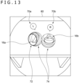
- FIG. 13 also illustrates an example of the camera AR video 60.
- the figure illustrates the camera AR video 60 including the guide display in the third mode.
- the input device 16 both the input device 16a and the input device 16b in this case
- the distance between the HMD 100 and the input device 16 both the input device 16a and the input device 16b in this case
- the image generating section 272 generates the camera AR video 60 including the guide display in the third mode for each of the input device 16a and the input device 16b.
- an approximate position guide 70a, an approximate position guide 70b, an insertion position guide 72, and insertion direction guides 74 are displayed so as to be superimposed on the captured image captured by the imaging devices 14.
- the insertion position guide 72 is an object as a first object for assisting the user in correctly gripping the controller, and is specifically an annular guide object that indicates a part through which the user is to insert a hand (that is, the position of the curved portion 23) in the input device 16.
- the image generating section 272 identifies the curved portion 23 of the HMD 100 appearing in the captured image on the basis of the position and the attitude of the HMD 100 estimated by the estimation processing section 230.
- the image generating section 272 disposes the insertion position guide 72 in the vicinity of the curved portion 23. Specifically, the image generating section 272 disposes the insertion position guide 72 so as to surround the periphery of the curved portion 23.
- the insertion position guide 72 may be an object that indicates a part that the user is to grip (that is, the position of the gripping portion 21) in the input device 16.
- the image generating section 272 may identify the gripping portion 21 of the HMD 100 appearing in the captured image on the basis of the position and attitude of the HMD 100 estimated by the estimation processing section 230.
- the image generating section 272 may dispose the insertion position guide 72 in the vicinity of the gripping portion 21. Specifically, the image generating section 272 may dispose the insertion position guide 72 to surround the periphery of the gripping portion 21.
- the curved portion 23 of the input device 16a appears in the captured image, and therefore, the insertion position guide 72 is disposed in the vicinity of the curved portion 23 of the input device 16a.
- the curved portion 23 of the input device 16b does not appear in the captured image, and therefore, no insertion position guide 72 is disposed for the input device 16b.
- the insertion direction guides 74 are an annular guide object as a second object that moves in a direction in which the user is to insert a hand in the input device 16.
- the insertion direction guide 74 indicates the direction in which the user is to insert a hand in the input device 16 by movement thereof in the camera AR video.
- the insertion direction guide 74 may be a line thinner than the insertion position guide 72.
- the image generating section 272 identifies the curved portion 23 of the input device 16 appearing in the captured image and the direction in which to insert a hand (for example, a direction from the curved portion 23 to the gripping portion 21) on the basis of the position and the attitude of the input device 16 estimated by the estimation processing section 230.
- the image generating section 272 sets, in the camera AR video 64, an animation such that the insertion direction guide 74 moves on the periphery of the input device 16 in the direction from the curved portion 23 to the gripping portion 21.
- This animation may be such that a plurality of insertion direction guides 74 move sequentially in the direction from the curved portion 23 to the gripping portion 21.
- the image generating section 272 may increase the transmittance of the insertion direction guide 74 as the insertion direction guide 74 moves and approaches the gripping portion 21.
- the image generating section 272 switches the guide display for the input device 16a from the third mode to the second mode in a case where the input device 16 ceases to appear in the captured image captured by the imaging devices 14 or the distance between the HMD 100 and the input device 16a exceeds 1.3 meters and the tracking of the input device 16a by the estimation processing section 230 is continued (the estimated value of the position of the input device 16a is output by the estimation processing section 230) while the guide display for the input device 16a is set in the third mode.
- the image generating section 272 switches the guide display for the input device 16a from the second mode to the first mode. The same is true for the switching of the guide display for the input device 16b.
- the image generating section 272 generates a camera AR video switched to guide display in a fourth mode in a case where a non-stationary state of the input device 16 is continued for a first time (one second in the embodiment) or more during the guide display in the third mode, or in other words, in a case where the stillness determining section 262 continues to determine for the first time (one second in the embodiment) or more that the input device 16 is in a non-stationary state, during the guide display in the third mode.
- the switching from the guide display in the third mode to the guide display in the fourth mode typically occurs in a case where the user holds the input device 16 in a hand.
- FIG. 14 also illustrates an example of the camera AR video 60.
- the guide display in the third mode is set for the input device 16a in a stationary state.
- the guide display in the fourth mode is set for the input device 16b that is held in a hand by the user and thus set in a non-stationary state.
- the approximate position guide 70b and the insertion position guide 72 are displayed, whereas the insertion direction guide 74 is in a non-display state.
- the image generating section 272 ends the animation of the insertion direction guide 74 added to the input device 16b thus far. This is because a distance between the user and the input device 16 becomes considerably shorter when the user holds the input device 16 in a hand and the user seeing the insertion direction guide 74 (animation) tends to be caused to have a feeling of strangeness when the insertion direction guide 74 (animation) is displayed in this state.
- the image generating section 272 in a case where contact of a finger of the user with any one of the operating members 22 of the input device 16 is detected during the guide display in the fourth mode, the image generating section 272 generates a camera AR video switched to guide display in a fifth mode.
- the guide display in the fifth mode erases all of the guide objects, or in other words, sets all of the guide objects in a non-display state.
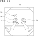
- FIG. 15 also illustrates an example of the camera AR video 60.
- the guide display in the fourth mode is set for the input device 16a held in a hand by the user and thus set in a non-stationary state, and the approximate position guide 70a and the insertion position guide 72 are added to the input device 16a.
- the guide display for the input device 16b whose operating member 22 is touched by a finger of the user has made a transition from the fourth mode to the fifth mode, so that the approximate position guide 70b and the insertion position guide 72 are set in a non-display state.
- the initial setting application of the HMD 100 may proceed to next setting processing (for example, processing of editing a play area or the like) using the input device 16a and the input device 16b in a case where fingers of the user touch both the input device 16a and the input device 16b.
- next setting processing for example, processing of editing a play area or the like
- the image generating section 272 switches the guide display for the input device 16a from the fifth mode to the fourth mode.
- the image generating section 272 switches the guide display for the input device 16a from the fourth mode to the third mode in a case where a stationary state of the input device 16a continues for a second time (10 seconds in the embodiment) or more, the second time being longer than the first time, or in other words, in a case where the stillness determining section 262 continues to determine for the second time (10 seconds in the embodiment) or more that the input device 16a is in a non-stationary state, while the guide display for the input device 16a is set in the fourth mode.
- the guide display for the input device 16b The same is true for the guide display for the input device 16b.
- the image generating section 272 sets the insertion direction guide 74 in a non-display state when the non-stationary state of the input device 16 continues for a relatively short time, whereas the image generating section 272 resumes the display of the insertion direction guide 74 on condition that the stationary state of the input device 16 continues for a relatively long time.
- the insertion direction guide 74 is not easily displayed, and therefore, the user is not easily caused to have a feeling of strangeness.
- the information processing system 1 in the embodiment presents, to the user, an AR image in which the insertion position guide 72 and the insertion direction guide 74 are added to the image obtained by capturing in the front direction of the user wearing the HMD 100. It is thereby possible to assist the user wearing the HMD 100 in correctly inserting a hand into the input device 16 and correctly gripping the input device 16.
- the estimation processing section 230 of the information processing device 10 in the embodiment estimates the position and the attitude of the input device 16 on the basis of both the image obtained by capturing the input device 16 (in other words, the captured image in which the input device 16 appears) and the sensor data transmitted from the input device 16.
- the estimation processing section 230 may use the image obtained by capturing the input device 16 as in the first estimation processing section 240 but may not use the sensor data transmitted from the input device 16 to estimate the position and the attitude of the input device 16.
- the estimation processing section 230 may use the sensor data transmitted from the input device 16 as in the second estimation processing section 250 but may not use the image obtained by capturing the input device 16 to estimate the position and the attitude of the input device 16.
- the functions of the information processing device 10 described in the embodiment may be implemented in the HMD 100.
- the HMD 100 may include the functions of the information processing device 10 described in the embodiment.
- the information processing device 10 in the embodiment may be the HMD 100.
- the imaging devices 14 are attached to the HMD 100. However, the imaging devices 14 may be attached to positions other than those of the HMD 100.
- An information processing device including:
- the information processing device it is possible to assist the user wearing the head-mounted display in correctly gripping the controller.
- the information processing device in which the display control section further displays the first object indicating the part to be gripped in a vicinity of the gripping portion of the controller appearing in the captured image on the basis of the estimation result of the position of the controller.
- the information processing device it is possible to assist the user wearing the head-mounted display in correctly gripping the controller.
- the user wearing the head-mounted display can be assisted in correctly inserting the hand through the curved portion of the controller, and can therefore be assisted in correctly gripping the controller.
- the information processing device in which the display control section sets the second object in a non-display state in a case where a non-stationary state of the controller continues for a first time or more.
- the information processing device in which the display control section resumes the display of the second object in a case where a stationary state of the controller continues for a second time or more, the second time being longer than the first time, after the non-stationary state of the controller continues for the first time or more and the second object is set in a non-display state.
- the information processing device according to any one of Items 1 to 6, in which the display control section displays the first object in a case where the controller appears in the captured image and a distance between the head-mounted display and the controller is equal to or less than a predetermined threshold value.
- the display of the first object is suppressed while the controller is located at a position distant from the user.
- the user is thereby easily prevented from misunderstanding as if the first object indicated another object present between the controller and the user.
- a controller display method performed by a computer including:
- controller display method it is possible to assist the user wearing the head-mounted display in correctly gripping the controller.
- a computer program for making a computer implement :
- the present invention is applicable to an information processing device and an information processing system.
Landscapes
- Engineering & Computer Science (AREA)
- Theoretical Computer Science (AREA)
- General Engineering & Computer Science (AREA)
- Physics & Mathematics (AREA)
- Human Computer Interaction (AREA)
- Multimedia (AREA)
- General Physics & Mathematics (AREA)
- Optics & Photonics (AREA)
- Computer Graphics (AREA)
- Software Systems (AREA)
- Computer Hardware Design (AREA)
- Computer Vision & Pattern Recognition (AREA)
- Health & Medical Sciences (AREA)
- Life Sciences & Earth Sciences (AREA)
- Biophysics (AREA)
- Cardiology (AREA)
- General Health & Medical Sciences (AREA)
- Heart & Thoracic Surgery (AREA)
- User Interface Of Digital Computer (AREA)
- Position Input By Displaying (AREA)
- Length Measuring Devices By Optical Means (AREA)
Abstract
A captured image obtaining section 212 obtains a captured image resulting from capturing in a front direction of a user wearing a head-mounted display (HMD 100). An estimation processing section 230 estimates the position of an input device 16 on the basis of the captured image in which a controller (input device 16) including a gripping portion to be gripped by the user after the user inserts a hand through a curved portion appears. A display control section 276 displays the captured image resulting from capturing in the front direction of the user on the HMD 100. The display control section 276 further displays an object indicating a part to be gripped by the user together with the captured image on the basis of an estimation result of the position of the input device 16.
Description
- The present invention relates to an information processing device, a controller display method, and a computer program.
- An image display system has spread which enables a user wearing a head-mounted display to view a target space from a free viewpoint. For example, electronic content for realizing virtual reality (VR) by setting a virtual three-dimensional space as a display target and displaying an image corresponding to a sight line direction of the user on the head-mounted display is known (the electronic content will hereinafter be referred to also as "VR content"). The use of the head-mounted display can also enhance a sense of immersion in video and improve operability of an application such as a game.
- In addition, a walkthrough system has also been developed which enables the user wearing the head-mounted display to virtually walk around in a space displayed as the VR content by moving physically. In addition, video see-through has also been realized in which three-dimensional content is displayed so as to be superimposed on the video of a surrounding real world captured by a camera included in the head-mounted display.
- The user using the head-mounted display may put on the head-mounted display without holding a controller in a hand, and try to hold the controller in a hand after putting on the head-mounted display. In this case, the user can view the video of the surroundings captured by the camera of the head-mounted display, but may not know how to hold the controller until the user is accustomed to the shape of the controller.
- It is an object of the present invention to provide a technology for assisting a user wearing a head-mounted display in correctly gripping a controller.
- In order to solve the above problem, an information processing device according to an aspect of the present invention includes a captured image obtaining section configured to obtain a captured image resulting from capturing a front of a user wearing a head-mounted display, an estimating section configured to estimate a position of a controller including a gripping portion to be gripped by the user on the basis of the captured image in which the controller appears, and a display control section configured to display the captured image resulting from capturing the front of the user on the head-mounted display. The display control section further displays a first object indicating a part to be gripped by the user together with the captured image on the basis of an estimation result of the position of the controller.
- Another aspect of the present invention is a controller display method. This method performed by a computer includes a step of obtaining a captured image resulting from capturing a front of a user wearing a head-mounted display, a step of estimating a position of a controller including a gripping portion to be gripped by the user on the basis of the captured image in which the controller appears, and a step of displaying the captured image resulting from capturing the front of the user on the head-mounted display. The displaying step further displays a first object indicating a part to be gripped by the user together with the captured image on the basis of an estimation result of the position of the controller.
- It is to be noted that any combinations of the above constituent elements as well as modes obtained by converting expressions of the present invention between a system, a computer program, a recording medium having the computer program readably recorded thereon, a data structure, and the like are also effective as modes of the present invention.
-
- [
FIG. 1 ]
FIG. 1 is a diagram illustrating an example of a configuration of an information processing system in an embodiment. - [
FIG. 2 ]
FIG. 2 is a diagram illustrating an example of an external shape of an HMD. - [
FIG. 3 ]
FIG. 3 is a diagram illustrating functional blocks of the HMD. - [
FIG. 4 ]
FIG. 4(a) is a diagram illustrating a shape of an input device for a left hand, andFIG. 4(b) is a diagram illustrating a shape of an input device for a right hand. - [
FIG. 5 ]
FIG. 5 is a diagram illustrating the shape of the input device for the right hand. - [
FIG. 6 ]
FIG. 6 is a diagram illustrating an example of a part of an image obtained by capturing an input device. - [
FIG. 7 ]
FIG. 7 is a block diagram illustrating functional blocks of the input device. - [
FIG. 8 ]
FIG. 8 is a block diagram illustrating functional blocks of an information processing device. - [
FIG. 9 ]
FIG. 9 is a flowchart illustrating position and attitude estimation processing. - [
FIG. 10 ]
FIG. 10 is a diagram illustrating an internal configuration of an estimation processing section. - [
FIG. 11 ]
FIG. 11 is a diagram illustrating an example of transitions of guide display in a camera AR video. - [
FIG. 12 ]
FIG. 12 is a diagram illustrating an example of the camera AR video. - [
FIG. 13 ]
FIG. 13 is a diagram illustrating an example of the camera AR video. - [
FIG. 14 ]
FIG. 14 is a diagram illustrating an example of the camera AR video. - [
FIG. 15 ]
FIG. 15 is a diagram illustrating an example of the camera AR video. - In an initial stage of an initial setting flow of an information processing system that displays VR content on a head-mounted display, an information processing device (game machine or the like) and a controller (referred to also as an "input device" in an embodiment) are paired with each other. The head-mounted display can also be said to be a VR headset. The head-mounted display will hereinafter be referred to also as an "HMD." At a time point of the pairing, the controller is set in a power-on state, or in other words, set in a state of being supplied with power from a power supply such as a battery. After the pairing, a user mounts the HMD on a head portion thereof without holding the controller in a hand, and performs various kinds of adjustments. Then, in a final stage of the initial setting flow, the user holds the controller in a hand, and performs an operation related to the editing of a play area in which the user wearing the HMD can move.
- When the user is to hold the controller in a hand to edit the play area, the user can view the video of a surrounding real world captured by a camera of the HMD. However, it is not easy for an unaccustomed user to find the controller on the basis of the video captured by the camera of the HMD, and determine the attitude of the controller correctly and grip the controller correctly.
- Accordingly, the information processing system according to the embodiment adds information assisting in correctly gripping the controller to the video captured by the camera of the HMD, and presents the resulting video to the user. Specifically, as information assisting in correctly gripping the controller, an object indicating a part to be gripped is added in the vicinity of a gripping portion of the controller appearing in a captured image. In the embodiment, the controller includes a curved portion for the user to insert a hand in addition to the gripping portion, and as the information assisting in correctly gripping the controller, an object indicating the part through which to insert a hand is added in the vicinity of the curved portion of the controller appearing in the captured image. The user wearing the HMD is thereby assisted in correctly gripping the controller.
-
FIG. 1 illustrates an example of a configuration of aninformation processing system 1 in an embodiment. Theinformation processing system 1 includes aninformation processing device 10, arecording device 11, an HMD 100, aninput device 16 held by the user and operated by fingers thereof, and anoutput device 15 that outputs an image and sound. Theoutput device 15 may be a television set. Theinformation processing device 10 is connected to anexternal network 2 such as the Internet via an access point (AP) 17. TheAP 17 has functions of a wireless access point and a router. Theinformation processing device 10 may be connected to theAP 17 by a cable, or may be connected to theAP 17 by a known wireless communication protocol. - The
recording device 11 records system software and applications such as game software. Theinformation processing device 10 may download various applications such as the game software from a content server to therecording device 11 via thenetwork 2. Theinformation processing device 10 executes the various applications, and supplies theHMD 100 with image data and audio data on an application intended for output (which data can also be said to be the data on VR content). Theinformation processing device 10 and theHMD 100 may be connected to each other by a known wireless communication protocol, and may be connected to each other by a cable. - The
HMD 100 is a display device that displays an image on a display panel that is located in front of eyes of the user when the user wears theHMD 100 on the head portion thereof. TheHMD 100 individually and separately displays an image for the left eye on a display panel for the left eye and an image for the right eye on a display panel for the right eye. These images constitute parallax images as viewed from a left and a right viewpoint, and realize a stereoscopic view. The user views the display panel through optical lenses. Theinformation processing device 10 therefore supplies theHMD 100 with parallax image data resulting from correction of optical distortion by the lenses. - The
output device 15 is not necessary for the user wearing theHMD 100. However, the preparation of theoutput device 15 enables another user to view the display image of theoutput device 15. Theinformation processing device 10 may display the same image as the image viewed by the user wearing theHMD 100 on theoutput device 15. However, theinformation processing device 10 may display another image on theoutput device 15. For example, in a case where the user wearing theHMD 100 and another user plays a game together, a game image obtained from a character viewpoint of the other user may be displayed from theoutput device 15. - The
information processing device 10 and theinput device 16 may be connected to each other by a known wireless communication protocol, and may be connected to each other by a cable. Theinput device 16 includes a plurality of operating members such as operating buttons. The user operates the operating members by fingers while gripping theinput device 16. Theinput device 16 is used as a game controller when theinformation processing device 10 executes a game. For example, user operations related to the progress of the game are input to the operating members, and theinput device 16 transmits operation information thereof to theinformation processing device 10 to make the user operations reflected in the game. As a modification, theinput device 16 may be a controller that communicates with theHMD 100 and controls the operation of theHMD 100. - The
input device 16 is provided with an inertial measurement device (IMU) including a triaxial acceleration sensor and a triaxial angular velocity sensor. Theinput device 16 transmits sensor data measured by the IMU to theinformation processing device 10 in a predetermined cycle (for example, 800 Hz). - The game in the embodiment deals with not only the operation information on the operating members of the
input device 16 but also the position, the speed, the attitude, and the like of theinput device 16 as operation information, and reflects the operation information in the motion of a player character in a virtual three-dimensional space. For example, the operation information on the operating members may be used as information for moving the player character, and the operation information such as the position, the speed, and the attitude of theinput device 16 may be used as information for moving arms of the player character. When the motion of theinput device 16 is reflected in the motion of the player character having a weapon in a battle scene in the game, intuitive operations of the user are realized, and a sense of immersion in the game is enhanced. - In order to track the position and the attitude of the
input device 16, theinput device 16 is provided with a plurality of markers (light emitting units) that can be captured byimaging devices 14. Theinformation processing device 10 has a function of analyzing an image obtained by capturing theinput device 16 and estimating the position and the attitude of theinput device 16 in a real space (which function will hereinafter be referred to also as a "first estimating function"). - The
HMD 100 is mounted with a plurality of theimaging devices 14. The plurality ofimaging devices 14 are attached in different attitudes to different positions of a front surface of theHMD 100 such that an entire capturing range obtained by adding together capturing ranges of therespective imaging devices 14 includes all of a field of view of the user. Theimaging devices 14 each include an image sensor capable of obtaining images of the plurality of markers of theinput device 16. In a case where the markers emit visible light, for example, theimaging devices 14 each include a visible light sensor used in an ordinary digital video camera, such as a CCD (Charge Coupled Device) sensor or a CMOS (Complementary Metal Oxide Semiconductor) sensor. In a case where the markers emit invisible light, theimaging devices 14 each include an invisible light sensor. - The plurality of
imaging devices 14 capture the front of the user in a predetermined period (for example, 120 frames/sec) in synchronized timing, and transmit the data on an image obtained by capturing the real space (which image will hereinafter be referred to also as a "captured image") to theinformation processing device 10. The captured image in the embodiment is an image obtained by capturing the real space in a direction of the front of the user wearing the HMD 100 (in a direction in which the face of the user is oriented). - The
information processing device 10 performs the first estimating function and thereby identifies the positions of a plurality of marker images of theinput device 16 included in the captured image. Incidentally, while oneinput device 16 may be captured by the plurality ofimaging devices 14 in same timing, theinformation processing device 10 may synthesize the plurality of captured images and identify the positions of the marker images because attachment positions and attachment attitudes of theimaging devices 14 are known. - The three-dimensional shape of the
input device 16 and the position coordinates of the plurality of markers arranged on the surface of theinput device 16 are known. Theinformation processing device 10 estimates the position and the attitude in the real space of theinput device 16 on the basis of the position coordinates of the plurality of marker images in the captured image. The position of theinput device 16 may be estimated as a coordinate value in world coordinates in a three-dimensional space having a reference position as an origin. The reference position may be position coordinates (latitude, longitude, and altitude (height above the sea level)) set before a start of the game. In addition, the attitude of theinput device 16 may be expressed by an inclination or an angle on each of three axes with respect to a predetermined reference attitude. - The
information processing device 10 in the embodiment has a function of analyzing the sensor data transmitted from theinput device 16 and estimating the position and the attitude of theinput device 16 in the real space (which function will hereinafter be referred to also as a "second estimating function"). Theinformation processing device 10 derives the position and the attitude of theinput device 16 by using an estimation result of the first estimating function and an estimation result of the second estimating function. Theinformation processing device 10 in the embodiment integrates the estimation result of the first estimating function and the estimation result of the second estimating function by utilizing a state estimating technology using a Kalman filter, and thereby estimates the state of theinput device 16 at a present time with high accuracy. -
FIG. 2 illustrates an example of an external shape of theHMD 100. TheHMD 100 includes anoutput mechanism unit 102 and amounting mechanism unit 104. The mountingmechanism unit 104 includes a mountingband 106 that encircles the head portion and fixes theHMD 100 to the head portion when the user puts on the mountingband 106. The mountingband 106 is of a material or a structure that allows a length adjustment thereof according to the circumference of the head of the user. - The
output mechanism unit 102 includes acasing 108 having such a shape as to cover the left and right eyes in a state in which the user wears theHMD 100, and internally includes the display panel that squarely faces the eyes at a time of the wearing. The display panel may be a liquid crystal panel, an organic EL panel, or the like. Further included in thecasing 108 is a pair of left and right optical lenses that are located between the display panel and the eyes of the user and that expand the viewing angle of the user. TheHMD 100 may further include speakers or earphones at positions corresponding to ears of the user, or may be configured to be connected with external headphones. - An external surface on the front side of the
casing 108 is provided withimaging devices imaging devices 14. With a frontward direction of the face of the user as a reference, theimaging device 14a is attached to an upper right corner of the external surface on the front side such that a camera optical axis thereof is directed rightward and obliquely upward, theimaging device 14b is attached to an upper left corner of the external surface on the front side such that a camera optical axis thereof is directed leftward and obliquely upward, theimaging device 14c is attached to a lower right corner of the external surface on the front side such that a camera optical axis thereof is directed rightward and obliquely downward, and theimaging device 14d is attached to a lower left corner of the external surface on the front side such that a camera optical axis thereof is directed leftward and obliquely downward. Because the plurality ofimaging devices 14 are thus installed, an entire capturing range obtained by adding together the respective capturing ranges of the plurality ofimaging devices 14 includes all of the field of view of the user. The field of view of the user may be a field of view of the user in a three-dimensional virtual space. - The
HMD 100 transmits sensor data detected by the IMU and image data captured by theimaging device 14 to theinformation processing device 10, and receives game image data and game sound data generated in theinformation processing device 10. -
FIG. 3 illustrates a functional block of theHMD 100. Acontrol unit 120 is a main processor that processes various kinds of data such as image data, audio data, and sensor data as well as instructions, and performs output. Thecontrol unit 120 may include a CPU (Central Processing Unit) and a GPU (Graphics Processing Unit). Astorage unit 122 temporarily stores the data and the instructions processed by thecontrol unit 120 and the like. AnIMU 124 obtains the sensor data related to motion of theHMD 100. TheIMU 124 may include at least a triaxial acceleration sensor and a triaxial angular velocity sensor. TheIMU 124 detects the values (sensor data) of respective axial components in a predetermined cycle (for example, 800 Hz). - A
communication control unit 128 transmits data output from thecontrol unit 120 to the externalinformation processing device 10 by wired or wireless communication via a network adapter or an antenna. In addition, thecommunication control unit 128 receives data from theinformation processing device 10, and outputs the data to thecontrol unit 120. - When the
control unit 120 receives the game image data and the game sound data from theinformation processing device 10, thecontrol unit 120 supplies the game image data to adisplay panel 130 to make a display thereof and supplies the game sound data to anaudio output unit 132 to perform an audio output thereof. Thedisplay panel 130 includes adisplay panel 130a for the left eye and adisplay panel 130b for the right eye. A pair of parallax images are displayed on the respective display panels. In addition, thecontrol unit 120 causes sensor data from theIMU 124, audio data from amicrophone 126, and captured image data from theimaging devices 14 to be transmitted from thecommunication control unit 128 to theinformation processing device 10. -
FIG. 4(a) illustrates the shape of aninput device 16a for a left hand. Theinput device 16a for the left hand includes acase body 20, a plurality ofoperating members members 22" in a case where the plurality ofoperating members markers 30 that emit light to the outside of thecase body 20. Themarkers 30 may have an emitting unit having a circular cross section. The operatingmembers 22 may include an analog stick operated by tilting, a depression type button, and the like. Thecase body 20 includes a grippingportion 21 and acurved portion 23 that couples a case body head portion and a case body bottom portion to each other. The user puts the left hand through thecurved portion 23, and grips the grippingportion 21. The user operates the operatingmembers portion 21. -
FIG. 4(b) illustrates the shape of aninput device 16b for a right hand. Theinput device 16b for the right hand includes acase body 20, a plurality ofoperating members members 22" in a case where the plurality ofoperating members markers 30 that emit light to the outside of thecase body 20. The operatingmembers 22 may include an analog stick operated by tilting, a depression type button, and the like. Thecase body 20 includes a grippingportion 21 and acurved portion 23 that couples a case body head portion and a case body bottom portion to each other. The user puts the right hand through thecurved portion 23, and grips the grippingportion 21. The user operates the operatingmembers portion 21. -
FIG. 5 illustrates the shape of theinput device 16b for the right hand. Theinput device 16b includes operatingmembers operating members FIG. 4(b) . In a state of gripping the grippingportion 21, the user operates the operatingmember 22i by using an index finger of the right hand, and operates the operatingmember 22j by using a middle finger thereof. In the following, in a case where theinput device 16a and theinput device 16b are not particularly distinguished from each other, theinput device 16a and theinput device 16b will be referred to as an "input device 16." Theinput device 16 in the embodiment is a controller including the grippingportion 21 to be gripped by the user after the user inserts a hand through thecurved portion 23. -
Operating members 22 provided to theinput device 16 may have a touch sensing function that recognizes a finger on the basis of a mere touch thereof without pressing. As for theinput device 16b for the right hand, the operatingmembers member 22, a touch sensor is preferably included in an operatingmember 22 such that the touch sensor does not come into contact with a mounting surface such as a table when theinput device 16 is placed on the mounting surface. - The
markers 30 are a light emitting unit that emits light to the outside of thecase body 20. Themarkers 30 include, in the surface of thecase body 20, a resin portion that diffuses and emits light from a light source such as an LED (Light Emitting Diode) element to the outside. Themarkers 30 are captured by theimaging devices 14, and are used for tracking processing of theinput device 16. - The
information processing device 10 uses the captured image captured by theimaging devices 14 for the tracking processing of theinput device 16 and SLAM (Simultaneous Localization and Mapping) processing of theHMD 100. In the embodiment, of images captured by theimaging devices 14 at 120 frames/sec, gray scale images captured at 60 frames/sec may be used for the tracking processing of theinput device 16, and other full color images captured at 60 frames/sec may be used for processing of simultaneously performing self-position estimation and environmental map generation of theHMD 100. -
FIG. 6 illustrates an example of a part of an image obtained by capturing theinput device 16. This image is an image obtained by capturing theinput device 16b held by the right hand, and includes images of the plurality ofmarkers 30 that emit light. Thecommunication control unit 128 in theHMD 100 transmits the image data captured by theimaging devices 14 to theinformation processing device 10 in real time. -
FIG. 7 is a block diagram illustrating functional blocks of theinput device 16. Acontrol unit 50 receives operation information input to the operatingmembers 22. In addition, thecontrol unit 50 receives sensor data detected by anIMU 32 and sensor data detected bytouch sensors 24. As described above, thetouch sensors 24 are attached to at least some of the plurality of operatingmembers 22, and sense states in which fingers of the user are in contact with the operatingmembers 22. - The
IMU 32 obtains the sensor data related to motion of theinput device 16. TheIMU 32 includes at least anacceleration sensor 34 that detects triaxial acceleration data and anangular velocity sensor 36 that detects triaxial angular velocity data. Theacceleration sensor 34 and theangular velocity sensor 36 detect the values (sensor data) of respective axial components in a predetermined cycle (for example, 800 Hz). Thecontrol unit 50 supplies the received operation information and the received sensor data to acommunication control unit 54. Thecommunication control unit 54 transmits the operation information and the sensor data to theinformation processing device 10 by wired or wireless communication via a network adapter or an antenna. - The
input device 16 includes a plurality oflight sources 58 for lighting the plurality ofmarkers 30. Thelight sources 58 may be an LED element that emits light in a predetermined color. When thecommunication control unit 54 obtains a light emission instruction from theinformation processing device 10, thecontrol unit 50 makes thelight sources 58 emit light and thereby lights themarkers 30 on the basis of the light emission instruction. Incidentally, while onelight source 58 is provided for onemarker 30 in the example illustrated inFIG. 7 , onelight source 58 may light a plurality ofmarkers 30. -
FIG. 8 is a block diagram illustrating functional blocks of theinformation processing device 10. Theinformation processing device 10 includes aprocessing section 200 and a communicatingsection 202. Theprocessing section 200 includes an obtainingsection 210, anapplication executing section 220, an imagesignal processing section 222, a markerinformation retaining section 224, astate retaining section 226, anestimation processing section 230, an image signal processing section 268, aSLAM processing section 270, animage generating section 272, and animage output section 274. The obtainingsection 210 includes a capturedimage obtaining section 212, a sensordata obtaining section 214, and an operationinformation obtaining section 216. Theestimation processing section 230 includes a firstestimation processing section 240, a secondestimation processing section 250, a thirdestimation processing section 260, and astillness determining section 262. - The communicating
section 202 communicates with an external device according to a predetermined communication protocol. The external device includes theHMD 100, theoutput device 15, theinput device 16, a server not illustrated, and another information processing device. For example, the communicatingsection 202 receives the operation information on the operatingmembers 22 and the sensor data transmitted from theinput device 16, and supplies the operation information and the sensor data to the obtainingsection 210. In addition, the communicatingsection 202 receives the captured image data and the sensor data transmitted from theHMD 100, and supplies the captured image data and the sensor data to the obtainingsection 210. - The
information processing device 10 includes a computer. The computer implements the various functions illustrated inFIG. 8 by executing a program. The computer includes, as hardware, a memory into which to load the program, one or more processors (a CPU, a GPU, and the like) for executing the loaded program, an auxiliary storage device, another LSI, and the like. The processor may include a plurality of electronic circuits including a semiconductor integrated circuit or an LSI. The plurality of electronic circuits may be mounted on one chip, or may be mounted on a plurality of chips. The functional blocks illustrated inFIG. 8 are implemented by cooperation between hardware and software. Hence, it is to be understood by those skilled in the art that these functional blocks can be implemented in various forms by only hardware, only software, or combinations of hardware and software. - The captured
image obtaining section 212 obtains the full color images for the SLAM processing of theHMD 100, and supplies the full color images to the image signal processing section 268. The image signal processing section 268 subjects the image data to image signal processing such as noise reduction and optical correction (shading correction), and supplies the image data resulting from the image signal processing to theSLAM processing section 270. - The sensor
data obtaining section 214 obtains the sensor data transmitted from theHMD 100, and supplies the sensor data to theSLAM processing section 270. TheSLAM processing section 270 simultaneously performs self-position estimation and environmental map generation of theHMD 100 on the basis of the image data supplied from the capturedimage obtaining section 212 and the sensor data supplied from the sensordata obtaining section 214. - The captured
image obtaining section 212 obtains the gray scale images for the tracking processing of theinput device 16, and supplies the gray scale images to the imagesignal processing section 222. The imagesignal processing section 222 subjects the image data to image signal processing such as noise reduction and optical correction (shading correction), and supplies the image data resulting from the image signal processing to the firstestimation processing section 240. - The first
estimation processing section 240 includes a marker image coordinate identifyingsection 242, a position and attitude deriving section 244, and anoise deriving section 248. The firstestimation processing section 240 implements the first estimating function of estimating the position and the attitude of theinput device 16 on the basis of the image obtained by capturing theinput device 16. The firstestimation processing section 240 extracts marker images obtained by capturing the plurality ofmarkers 30 of theinput device 16 from the captured image, and estimates the position and the attitude of theinput device 16 from an arrangement of a plurality of the extracted marker images. The firstestimation processing section 240 outputs the estimated position and attitude of theinput device 16 to the thirdestimation processing section 260 together with the variance of noise (error) thereof. - The sensor
data obtaining section 214 obtains the sensor data transmitted from theinput device 16, and supplies the sensor data to the secondestimation processing section 250. The secondestimation processing section 250 implements the second estimating function of estimating the position and the attitude of theinput device 16 on the basis of the sensor data indicating the acceleration and angular velocity of theinput device 16. In the embodiment, the second estimating function is a function of performing a state predicting step in a Kalman filter. The secondestimation processing section 250 estimates a state vector at this time by adding a state vector change amount obtained by integral operation on the supplied sensor data to a state vector (position, speed, and attitude) at a previous time. The secondestimation processing section 250 outputs the estimated state vector to the thirdestimation processing section 260 together with the variance of noise thereof. Incidentally, the change amount obtained by the integral operation accumulates noise over time. Thus, the state vector (position, speed, and attitude) estimated by the secondestimation processing section 250 tends to deviate from an actual state vector (position, speed, and attitude). - The third
estimation processing section 260 derives the position and the attitude of theinput device 16 with high accuracy from the position and attitude of theinput device 16 estimated by the firstestimation processing section 240 and the state vector (position, speed, and attitude) of theinput device 16 estimated by the secondestimation processing section 250. The thirdestimation processing section 260 may perform a filtering step (correcting step) of a UKF (unscented Kalman Filter). The thirdestimation processing section 260 obtains the state vector estimated by the secondestimation processing section 250 as a "prior estimated value," obtains the position and the attitude estimated by the firstestimation processing section 240 as an "observed value," calculates a Kalman gain, and obtains an "posterior estimated value" resulting from correcting the "prior estimated value" by using the Kalman gain. The "posterior estimated value" represents the position and attitude of theinput device 16 with high accuracy. The "posterior estimated value" is provided to theapplication executing section 220, and is recorded in thestate retaining section 226 to be used for the estimation of the state vector at a next time in the secondestimation processing section 250. - A method of increasing accuracy by integrating results of analysis using a plurality of sensors such as the
imaging devices 14 and theIMU 32 is known as sensor fusion. In the sensor fusion, times at which data is obtained by the respective sensors need to be expressed on a common time axis. In theinformation processing system 1, the imaging cycle of theimaging devices 14 and the sampling cycle of theIMU 32 are different from each other and are asynchronous with each other. Thus, by accurately managing the capturing times of images and the detection times of acceleration and angular velocity, the thirdestimation processing section 260 can estimate the position and the attitude of theinput device 16 with high accuracy. -
FIG. 9 is a flowchart illustrating position and attitude estimation processing by the firstestimation processing section 240. The capturedimage obtaining section 212 obtains the image data resulting from capturing the input device 16 (S10) and supplies the image data to the imagesignal processing section 222. The imagesignal processing section 222 subjects the image data to image signal processing such as noise reduction and optical correction (S12) and supplies the image data resulting from the image signal processing to the marker image coordinate identifyingsection 242. - The marker image coordinate identifying
section 242 identifies representative coordinates of the plurality of marker images included in the captured image (S14). In a case where the luminance of each pixel of a gray scale image is represented by 8 bits, and assumes a luminance value of 0 to 255, the marker images are captured as images having high luminance, as illustrated inFIG. 6 . The marker image coordinate identifyingsection 242 may identify a region of consecutive pixels having luminance values equal to or higher than a predetermined value (for example, a luminance value of 128) from the captured image, calculate gravity center coordinates of the consecutive pixel region, and thereby identify the representative coordinates of a marker image. - Incidentally, the captured image includes not only the marker images but also an image of a lighting device such as an electric light. Accordingly, the marker image coordinate identifying
section 242 investigates whether the consecutive pixel region having the luminance values equal to or higher than the predetermined value corresponds to a marker image by checking the consecutive pixel region against a few predetermined criteria. For example, in a case where the consecutive pixel region is too large, or in a case where the consecutive pixel region has an elongated shape, it is certain that the consecutive pixel region does not correspond to a marker image, and therefore, the marker image coordinate identifyingsection 242 may determine that such a consecutive pixel region is not a marker image. The marker image coordinate identifyingsection 242 calculates the gravity center coordinates of a consecutive pixel region satisfying the predetermined criteria, identifies the gravity center coordinates as the representative coordinates (marker image coordinates) of a marker image, and stores the identified representative coordinates in a memory (not illustrated). - The marker
information retaining section 224 retains three-dimensional coordinates of each marker in a three-dimensional model of theinput device 16 in the reference position and the reference attitude. A method of solving a PNP (Perspective n-Point) problem is known as a method for estimating the position and the attitude of an imaging device that captures an object whose three-dimensional shape and size are known from a captured image of the object. - In the embodiment, the position and attitude deriving section 244 reads the coordinates of N (N is an integer of 3 or more) marker images from a memory (not illustrated), and estimates the position and the attitude of the
input device 16 from the read coordinates of the N marker images and the three-dimensional coordinates of N markers in the three-dimensional model of theinput device 16. The position and attitude deriving section 244 estimates the position and the attitude of theimaging device 14 by using the following (Equation 1), and derives the position and attitude in the three-dimensional space of theinput device 16 on the basis of a result of the estimation.
[Math. 1]
- Here, (u, v) is marker image coordinates in the captured image, and (X, Y, Z) is position coordinates in the three-dimensional space of the
markers 30 when the three-dimensional model of theinput device 16 is in the reference position and the reference attitude. Incidentally, the three-dimensional model is a model that has perfectly the same shape and size as theinput device 16 and has markers arranged at the same positions. The markerinformation retaining section 224 retains the three-dimensional coordinates of each marker in the three-dimensional model in the reference position and the reference attitude. The position and attitude deriving section 244 obtains (X, Y, Z) by reading the three-dimensional coordinates of each marker from the markerinformation retaining section 224. - (fx, fy) is the focal length of the
imaging device 14, and (cx, cy) is an image principal point. Both are internal parameters of theimaging device 14. A matrix having r11 to r33 and t1 to t3 as elements is a rotation and translation matrix. In (Equation 1), (u, v), (fx, fy), (cx, cy), and (X, Y, Z) are known. The position and attitude deriving section 244 solves the equation for theN markers 30, and thereby obtains a rotation and translation matrix common to these markers. In the embodiment, the processing of estimating the position and the attitude of theinput device 16 is performed by solving the P3P problem. - Specifically, the position and attitude deriving section 244 extracts the coordinates of freely selected three marker images from among the coordinates of the plurality of marker images identified by the marker image coordinate identifying
section 242. The position and attitude deriving section 244 reads the three-dimensional coordinates of the markers in the three-dimensional model from the markerinformation retaining section 224, and solves the P3P problem by using (Equation 1). When the position and attitude deriving section 244 identifies a rotation and translation matrix common to the coordinates of the three extracted marker images, the position and attitude deriving section 244 calculates a reprojection error by using the marker image coordinates of theinput device 16 other than the coordinates of the three extracted marker images. - The position and attitude deriving section 244 extracts a predetermined number of combinations of the coordinates of three marker images. The position and attitude deriving section 244 identifies a rotation and translation matrix for each of the combinations of the coordinates of the three extracted marker images, and calculates a reprojection error for each. Then, the position and attitude deriving section 244 identifies a rotation and translation matrix providing a minimum reprojection error from among a predetermined number of reprojection errors, and derives the position and the attitude of the input device 16 (S16).
- The
noise deriving section 248 derives the variance of noise (error) of each of the estimated position and attitude (S18). The variance value of the noise corresponds to a degree of reliability of the estimated position and attitude. When the degree of reliability is high, the variance value is small. When the degree of reliability is low, the variance value is large. Thenoise deriving section 248 may derive the variance of the noise on the basis of distances between theimaging devices 14 and theinput device 16 and the positions of the marker images in an angle of view. For example, in a case where theimaging devices 14 are distant from theinput device 16 or extremely close to theinput device 16, or in a case where the marker images are located at an edge of the captured image, it is difficult to derive accurate gravity center coordinates of the marker images, and therefore a large noise variance tends to be derived. - Incidentally, it is certain that the degree of reliability of the position and the attitude which are estimated during the tracking processing (while the first estimating function is performed) is high. Thus, the
noise deriving section 248 may set the variance of the noise of each of the estimated position and the estimated attitude to a small fixed value. For example, thenoise deriving section 248 may set the variance of the position noise during the tracking processing to "0.5 mm" as a fixed value, and supply the set variance to the thirdestimation processing section 260. During the tracking processing, the firstestimation processing section 240 may output the variances of the position noise and the attitude noise to the thirdestimation processing section 260 together with information regarding the estimated position and attitude. However, in a case where the variances of the position noise and the attitude noise are fixed values, the noise variances may be output to the thirdestimation processing section 260 once at a time of a start of the tracking processing, and the thirdestimation processing section 260 may store and use the noise variances. - The position and attitude estimation processing of the first
estimation processing section 240 is performed in an imaging cycle of the images for the tracking of the input device 16 (60 frames/sec) (N in S20). When theapplication executing section 220 ends the execution of the application (game or the like), the position and attitude estimation processing of the firstestimation processing section 240 is ended (Y in S20). -
FIG. 10 illustrates an internal configuration of theestimation processing section 230. At time k, the firstestimation processing section 240 outputs the estimated position and attitude as an "observed value nk" and the variances of the position noise and the attitude noise as "observation noise Rk" to the thirdestimation processing section 260. - Observed Value nk: an observation vector at time k
- Observation Noise Rk: an error covariance matrix of the observed value at time k.
- The second
estimation processing section 250 reads a "state vector mk-1 | k-1 " and an "estimation error Pk-1 | k-1 " at a preceding time (at time k-1) from thestate retaining section 226, and inputs the "state vector mk-1 | k-1 " and the "estimation error Pk-1 | k-1 " to a predicting section. The state variable m in the embodiment includes the position, the speed, and the attitude of theinput device 16, and may further include an acceleration bias and an angular velocity bias. - State Vector mk-1 | k-1: the state vector at time k-1 estimated on the basis of information up to time k-1
- Estimation Error Pk-1 | k-1: an estimation error covariance matrix of a state at time k-1 estimated on the basis of the information up to time k-1
- In addition, the second
estimation processing section 250 obtains an acceleration ak and an angular velocity ωk of theinput device 16 from the sensordata obtaining section 214, and inputs the acceleration ak and the angular velocity ωk as "process input lk" to the predicting section. - Acceleration ak: acceleration at time k
- Angular Velocity ωk: angular velocity at time k
- Process Input lk: a process input vector at time k
- The second
estimation processing section 250 calculates the variance of acceleration noise and the variance of angular velocity noise from the acceleration ak and the angular velocity ωk and fixed noise parameters (including an axis shift, a scale shift, a value shift, and a bias shift), and inputs the variances as "process noise Qk" to the predicting section. - • Process Noise Qk: an error covariance matrix of the process input at time k
- The predicting section performs an integral operation on each of the acceleration ak and the angular velocity ωk, and performs an operation of calculating change amounts (that is, a position change amount, a speed change amount, and an attitude change amount) from the "state vector mk-1 | k-1," and adding the change amounts to the "state vector mk-1 | k-1." The predicting section calculates the speed change amount by integrating the acceleration ak, calculates the position change amount by integrating a speed estimated by using the speed change amount, and calculates the attitude change amount by integrating the angular velocity ωk. The predicting section outputs the "state vector mk | k-1" and the "estimation error Pk | k-1 " to the third
estimation processing section 260. - State Vector mk | k-1: the state vector at time k estimated on the basis of the information up to time k-1
- Estimation Error Pk | k-1: an estimation error covariance matrix of a state at time k estimated on the basis of the information up to time k-1
- The third
estimation processing section 260 obtains the "observed value nk" and the "observation noise Rk" from the firstestimation processing section 240, obtains the "state vector mk | k-1" and the "estimation error Pk | k-1 " from the secondestimation processing section 250, and calculates a Kalman gain for correcting the "state vector mk | k-1." The thirdestimation processing section 260 corrects the "state vector mk | k-1 " by using the Kalman gain, and outputs the "state vector mk | k" and the "estimation error Pk | k." - State Vector mk | k: the state vector at time k estimated on the basis of information up to time k
- Estimation Error Pk | k: an estimation error covariance matrix of the state at time k estimated on the basis of the information up to time k
- The "state vector mk | k" represents the position, the speed, and the attitude estimated with high accuracy. The "state vector mk | k" may be supplied to the
application executing section 220, and used for operation in the application. The "state vector mk | k" and the "estimation error Pk | k" are temporarily retained in thestate retaining section 226, and are read at a time of estimation processing at time k+1 in the secondestimation processing section 250. - In the
estimation processing section 230, the estimation processing of the firstestimation processing section 240 is performed in a cycle of 60 Hz, while the estimation processing of the secondestimation processing section 250 is performed in a cycle of 800 Hz. Therefore, during a period from the output of the observed value by the firstestimation processing section 240 to the output of a next observed value, the secondestimation processing section 250 sequentially updates the state vector. During this period, the state vector is not corrected. Theestimation processing section 230 in the embodiment performs a correcting step with the state at time k-1 immediately before the observation time k as a reference, that is, uses the observed value to correct the state in the past. - As described above, the
estimation processing section 230 estimates the position and attitude of theinput device 16 with high accuracy while the tracking processing of theinput device 16 is performed. However, when themarkers 30 of theinput device 16 are not captured by theimaging device 14, the firstestimation processing section 240 cannot perform the position and attitude estimation processing illustrated inFIG. 9 . - In the embodiment, even in a case where the
markers 30 of theinput device 16 do not appear in the captured image (are not captured by the imaging devices 14), theestimation processing section 230 estimates the position of theinput device 16, or in other words, continues the tracking of theinput device 16 on the basis of the sensor data on theHMD 100 and the sensor data on theinput device 16. For example, in a case of determining on the basis of the sensor data on theHMD 100 that theHMD 100 has moved in a right direction after theinput device 16 goes outside the angle of view of theimaging devices 14, theestimation processing section 230 may move the estimated position of theinput device 16 in a left direction from a previous position thereof by an amount corresponding to the movement of theHMD 100 in the right direction. Theestimation processing section 230 ends the processing of estimating the position of theinput device 16 in a case where a predetermined tracking ending condition (for example, the passage of a predetermined time, a large movement of theHMD 100, or the like) is satisfied under conditions where themarkers 30 of theinput device 16 do not appear in the captured image. - Returning to
FIG. 8 , thestillness determining section 262 determines whether or not theinput device 16 is still on the basis of the sensor data indicating the acceleration of theinput device 16, the sensor data being obtained by the sensordata obtaining section 214. Thestillness determining section 262 calculates the slope of the acceleration from time series data on the acceleration of theinput device 16, and determines whether or not theinput device 16 is still on the basis of the calculated slope. - The
stillness determining section 262 in the embodiment obtains a regression line by applying a least-square method to 100 acceleration values from the present time t to a past time (t-99), and identifies the slope of the regression line. Incidentally, the number of samples at a time of calculating the slope may be other than 100. Thestillness determining section 262 may calculate the slope in a sampling cycle of the sensor data, and thereby determine at all times whether or not theinput device 16 is still. - The
stillness determining section 262 determines that theinput device 16 is moving when the absolute value of the calculated slope is equal to or more than a predetermined threshold value Sth. Thestillness determining section 262 determines that theinput device 16 is still when the absolute value of the calculated slope is less than the threshold value Sth. Incidentally, in order to prevent frequent changing of a determination result, the stillness determining section 264 may determine that theinput device 16 is still when the absolute value of the calculated slope is consecutively less than the threshold value Sth a predetermined number of times (N3 times), and after determining that theinput device 16 is still, the stillness determining section 264 may determine that theinput device 16 is moving when the absolute value of the calculated slope is consecutively equal to or more than the threshold value Sth a predetermined number of times (N4 times). N3 and N4 may be a same number of times and may be different numbers of times. - As a modification, the
stillness determining section 262 may determine whether or not theinput device 16 is still on the basis of the captured image in which theinput device 16 appears, the captured image being obtained by the capturedimage obtaining section 212. As another modification, thestillness determining section 262 may determine whether or not theinput device 16 is still on the basis of time series changes in the position of theinput device 16 estimated by any one of the firstestimation processing section 240, the secondestimation processing section 250, and the thirdestimation processing section 260. - The captured
image obtaining section 212 further provides the captured image data transmitted from theHMD 100 to theapplication executing section 220 and theimage generating section 272. The sensordata obtaining section 214 further provides the sensor data transmitted from theHMD 100 to theapplication executing section 220 and theimage generating section 272. In addition, the sensordata obtaining section 214 further provides the sensor data transmitted from theinput device 16 to theapplication executing section 220 and theimage generating section 272. - The operation
information obtaining section 216 obtains the operation information indicating user operation input to theinput device 16, the operation information being transmitted from theinput device 16. The operationinformation obtaining section 216 provides the obtained operation information to theapplication executing section 220. - The
application executing section 220 executes various kinds of applications on the basis of the operation information input from the operationinformation obtaining section 216, the sensor data input from the sensordata obtaining section 214, the position and attitude information of theinput device 16 estimated by the estimation processing section 230 (for example, the third estimation processing section 260), and the like. For example, theapplication executing section 220 may make a VR game progress by executing a computer program that implements various kinds of processing related to the VR game. In the embodiment, theapplication executing section 220 executes an initial setting application of theHMD 100. - The
image generating section 272 and theimage output section 274 function as adisplay control section 276 that controls the display of electronic content on a display unit. The display unit includes at least thedisplay panel 130 of theHMD 100, and may further include the display of theoutput device 15. In the embodiment, thedisplay control section 276 displays a camera AR video to be described later on thedisplay panel 130 of theHMD 100 during the execution of the initial setting application of theHMD 100. - Specifically, the
image generating section 272 generates image data for display (for example, image data on VR content) to be displayed on theHMD 100 on the basis of the captured image data input from the capturedimage obtaining section 212, a result of execution of an application by theapplication executing section 220, and the like. Theimage output section 274 transmits the image data for display generated by theimage generating section 272 to theHMD 100 to display the image data on thedisplay panel 130 of theHMD 100. - In the embodiment, the
image generating section 272 generates an image of the initial setting application of theHMD 100 on the basis of a result of execution of the initial setting application of theHMD 100 by theapplication executing section 220. The image of the initial setting application of theHMD 100 includes the captured image captured by theimaging devices 14 of theHMD 100, the captured image being obtained by capturing the real space in the front direction of the user wearing theHMD 100. Specifically, the image of the initial setting application of theHMD 100 includes an augmented reality (AR) video (hereinafter referred to also as a "camera AR video") on the basis of a video in which the real space in the front direction of the user wearing theHMD 100 appears. Theimage output section 274 displays the camera AR video generated by theimage generating section 272 on thedisplay panel 130 of theHMD 100. - The camera AR video can include an image of a virtual object (hereinafter referred to also as a "guide object") that assists in correctly gripping the
input device 16. The guide object includes an approximate position guide and an insertion position guide to be described later. Theimage generating section 272 respectively and individually manages the state of theinput device 16a and the state of theinput device 16b (position and attitude or the like), and respectively and individually determines a guide object to be added to theinput device 16a and a guide object to be added to theinput device 16b in the camera AR video. -
FIG. 11 illustrates an example of transitions of guide display in the camera AR video. Theimage generating section 272 sets the guide display for theinput device 16 in a first mode, in a case where theestimation processing section 230 cannot track the position (for example, a coordinate value in a world coordinate system) of theinput device 16. The first mode suppresses the display of the guide object added to the video of theinput device 16, or in other words, sets the guide object in a non-display state. - In a case where the
estimation processing section 230 can track the position of theinput device 16, theimage generating section 272 determines whether or not theinput device 16 appears in the captured image captured by theimaging devices 14, that is, whether or not theinput device 16 is in the field of view of the user. In addition, theimage generating section 272 derives a distance between theHMD 100 and theinput device 16 on the basis of the estimated position of theinput device 16, and further determines whether or not the distance is equal to or less than a predetermined threshold value. This threshold value in the embodiment is 1.3 meters. However, an appropriate threshold value may be determined on the basis of the knowledge of a developer, an experiment using theinformation processing system 1, or the like. - The
image generating section 272 sets the guide display for theinput device 16 in a second mode when theinput device 16 does not appear in the captured image captured by theimaging devices 14 or the distance between theHMD 100 and theinput device 16 exceeds the above-described threshold value in a case where the position of theinput device 16 can be tracked. The second mode disposes the approximate position guide as a guide object to be added to the video of theinput device 16. - The
image generating section 272 sets the guide display for theinput device 16 in a third mode when theinput device 16 appears in the captured image captured by theimaging devices 14 and the distance between theHMD 100 and theinput device 16 is equal to or less than the above-described threshold value in a case where the position of theinput device 16 can be tracked. The third mode disposes the approximate position guide, the insertion position guide, and an insertion direction guide as guide objects to be added to the video of theinput device 16. -
FIG. 12 illustrates an example of acamera AR video 60. The figure illustrates thecamera AR video 60 including the guide display in the second mode. In the initial setting of theHMD 100 in the embodiment, the user puts theHMD 100 on the head portion of the user himself/herself, and is thereafter requested to grip theinput device 16. Here, suppose that both the position of theinput device 16a and the position of theinput device 16b can be tracked, but neither theinput device 16a nor theinput device 16b appears in the captured image captured by theimaging devices 14. Theimage generating section 272 generates thecamera AR video 60 including the guide display in the second mode for each of theinput device 16a and theinput device 16b. - In the
camera AR video 60 ofFIG. 12 , an approximate position guide 70a and anapproximate position guide 70b are displayed so as to be superimposed on the captured image captured by theimaging devices 14. Theapproximate position guide 70a is a guide object that indicates a rough position of theinput device 16a by the direction of an arrow. Theapproximate position guide 70b is a guide object that indicates a rough position of theinput device 16b by the direction of an arrow. Theimage generating section 272 sets the arrow of the approximate position guide 70a so as to point to the position of theinput device 16a estimated by theestimation processing section 230, and sets the arrow of theapproximate position guide 70b so as to point to the position of theinput device 16b estimated by theestimation processing section 230. -
FIG. 13 also illustrates an example of thecamera AR video 60. The figure illustrates thecamera AR video 60 including the guide display in the third mode. Suppose that the input device 16 (both theinput device 16a and theinput device 16b in this case) appears in the captured image captured by theimaging devices 14 during the guide display in the second mode, and that the distance between theHMD 100 and the input device 16 (both theinput device 16a and theinput device 16b in this case) has become equal to or less than 1.3 meters. In this case, theimage generating section 272 generates thecamera AR video 60 including the guide display in the third mode for each of theinput device 16a and theinput device 16b. In thecamera AR video 60 ofFIG. 13 , anapproximate position guide 70a, anapproximate position guide 70b, aninsertion position guide 72, and insertion direction guides 74 are displayed so as to be superimposed on the captured image captured by theimaging devices 14. - The
insertion position guide 72 is an object as a first object for assisting the user in correctly gripping the controller, and is specifically an annular guide object that indicates a part through which the user is to insert a hand (that is, the position of the curved portion 23) in theinput device 16. Theimage generating section 272 identifies thecurved portion 23 of theHMD 100 appearing in the captured image on the basis of the position and the attitude of theHMD 100 estimated by theestimation processing section 230. Theimage generating section 272 disposes the insertion position guide 72 in the vicinity of thecurved portion 23. Specifically, theimage generating section 272 disposes the insertion position guide 72 so as to surround the periphery of thecurved portion 23. - As a modification, the insertion position guide 72 may be an object that indicates a part that the user is to grip (that is, the position of the gripping portion 21) in the
input device 16. Theimage generating section 272 may identify the grippingportion 21 of theHMD 100 appearing in the captured image on the basis of the position and attitude of theHMD 100 estimated by theestimation processing section 230. Theimage generating section 272 may dispose the insertion position guide 72 in the vicinity of the grippingportion 21. Specifically, theimage generating section 272 may dispose the insertion position guide 72 to surround the periphery of the grippingportion 21. - Incidentally, in the camera AR video 64 of
FIG. 13 , thecurved portion 23 of theinput device 16a appears in the captured image, and therefore, theinsertion position guide 72 is disposed in the vicinity of thecurved portion 23 of theinput device 16a. In contrast, thecurved portion 23 of theinput device 16b does not appear in the captured image, and therefore, noinsertion position guide 72 is disposed for theinput device 16b. - The insertion direction guides 74 are an annular guide object as a second object that moves in a direction in which the user is to insert a hand in the
input device 16. The insertion direction guide 74 indicates the direction in which the user is to insert a hand in theinput device 16 by movement thereof in the camera AR video. The insertion direction guide 74 may be a line thinner than theinsertion position guide 72. Theimage generating section 272 identifies thecurved portion 23 of theinput device 16 appearing in the captured image and the direction in which to insert a hand (for example, a direction from thecurved portion 23 to the gripping portion 21) on the basis of the position and the attitude of theinput device 16 estimated by theestimation processing section 230. - In the embodiment, the
image generating section 272 sets, in the camera AR video 64, an animation such that the insertion direction guide 74 moves on the periphery of theinput device 16 in the direction from thecurved portion 23 to the grippingportion 21. This animation may be such that a plurality of insertion direction guides 74 move sequentially in the direction from thecurved portion 23 to the grippingportion 21. Theimage generating section 272 may increase the transmittance of the insertion direction guide 74 as the insertion direction guide 74 moves and approaches the grippingportion 21. - The
image generating section 272 switches the guide display for theinput device 16a from the third mode to the second mode in a case where theinput device 16 ceases to appear in the captured image captured by theimaging devices 14 or the distance between theHMD 100 and theinput device 16a exceeds 1.3 meters and the tracking of theinput device 16a by theestimation processing section 230 is continued (the estimated value of the position of theinput device 16a is output by the estimation processing section 230) while the guide display for theinput device 16a is set in the third mode. In addition, when the tracking of theinput device 16a by theestimation processing section 230 is ended, theimage generating section 272 switches the guide display for theinput device 16a from the second mode to the first mode. The same is true for the switching of the guide display for theinput device 16b. - Returning to
FIG. 11 , theimage generating section 272 generates a camera AR video switched to guide display in a fourth mode in a case where a non-stationary state of theinput device 16 is continued for a first time (one second in the embodiment) or more during the guide display in the third mode, or in other words, in a case where thestillness determining section 262 continues to determine for the first time (one second in the embodiment) or more that theinput device 16 is in a non-stationary state, during the guide display in the third mode. The switching from the guide display in the third mode to the guide display in the fourth mode typically occurs in a case where the user holds theinput device 16 in a hand. -
FIG. 14 also illustrates an example of thecamera AR video 60. In thecamera AR video 60 of the figure, the guide display in the third mode is set for theinput device 16a in a stationary state. In contrast, the guide display in the fourth mode is set for theinput device 16b that is held in a hand by the user and thus set in a non-stationary state. - In the guide display in the fourth mode, the
approximate position guide 70b and the insertion position guide 72 are displayed, whereas the insertion direction guide 74 is in a non-display state. In a case where the guide display for theinput device 16b makes a transition from the third mode to the fourth mode, theimage generating section 272 ends the animation of the insertion direction guide 74 added to theinput device 16b thus far. This is because a distance between the user and theinput device 16 becomes considerably shorter when the user holds theinput device 16 in a hand and the user seeing the insertion direction guide 74 (animation) tends to be caused to have a feeling of strangeness when the insertion direction guide 74 (animation) is displayed in this state. - Returning to
FIG. 11 , in a case where contact of a finger of the user with any one of the operatingmembers 22 of theinput device 16 is detected during the guide display in the fourth mode, theimage generating section 272 generates a camera AR video switched to guide display in a fifth mode. The guide display in the fifth mode erases all of the guide objects, or in other words, sets all of the guide objects in a non-display state. -
FIG. 15 also illustrates an example of thecamera AR video 60. In thecamera AR video 60 in the figure, the guide display in the fourth mode is set for theinput device 16a held in a hand by the user and thus set in a non-stationary state, and the approximate position guide 70a and the insertion position guide 72 are added to theinput device 16a. In contrast, the guide display for theinput device 16b whose operatingmember 22 is touched by a finger of the user has made a transition from the fourth mode to the fifth mode, so that theapproximate position guide 70b and the insertion position guide 72 are set in a non-display state. The initial setting application of theHMD 100 may proceed to next setting processing (for example, processing of editing a play area or the like) using theinput device 16a and theinput device 16b in a case where fingers of the user touch both theinput device 16a and theinput device 16b. - When the finger of the user is separated from the operating
member 22 while the guide display for theinput device 16a is set in the fifth mode, theimage generating section 272 switches the guide display for theinput device 16a from the fifth mode to the fourth mode. In addition, theimage generating section 272 switches the guide display for theinput device 16a from the fourth mode to the third mode in a case where a stationary state of theinput device 16a continues for a second time (10 seconds in the embodiment) or more, the second time being longer than the first time, or in other words, in a case where thestillness determining section 262 continues to determine for the second time (10 seconds in the embodiment) or more that theinput device 16a is in a non-stationary state, while the guide display for theinput device 16a is set in the fourth mode. The same is true for the guide display for theinput device 16b. - That is, the
image generating section 272 sets the insertion direction guide 74 in a non-display state when the non-stationary state of theinput device 16 continues for a relatively short time, whereas theimage generating section 272 resumes the display of the insertion direction guide 74 on condition that the stationary state of theinput device 16 continues for a relatively long time. Thus, even in a case where theinput device 16 is held unintentionally still while the user holds theinput device 16 in a hand, or in other words, while the distance between the user and theinput device 16 is considerably shorter, the insertion direction guide 74 is not easily displayed, and therefore, the user is not easily caused to have a feeling of strangeness. - The
information processing system 1 in the embodiment presents, to the user, an AR image in which theinsertion position guide 72 and the insertion direction guide 74 are added to the image obtained by capturing in the front direction of the user wearing theHMD 100. It is thereby possible to assist the user wearing theHMD 100 in correctly inserting a hand into theinput device 16 and correctly gripping theinput device 16. - The present invention has been described above on the basis of an embodiment thereof. The present embodiment is illustrative, and it is to be understood by those skilled in the art that combinations of constituent elements or processing processes are susceptible of various modifications and that such modifications also fall within the scope of the present invention.
- The
estimation processing section 230 of theinformation processing device 10 in the embodiment estimates the position and the attitude of theinput device 16 on the basis of both the image obtained by capturing the input device 16 (in other words, the captured image in which theinput device 16 appears) and the sensor data transmitted from theinput device 16. As a modification, theestimation processing section 230 may use the image obtained by capturing theinput device 16 as in the firstestimation processing section 240 but may not use the sensor data transmitted from theinput device 16 to estimate the position and the attitude of theinput device 16. As another modification, theestimation processing section 230 may use the sensor data transmitted from theinput device 16 as in the secondestimation processing section 250 but may not use the image obtained by capturing theinput device 16 to estimate the position and the attitude of theinput device 16. - The functions of the
information processing device 10 described in the embodiment may be implemented in theHMD 100. In other words, theHMD 100 may include the functions of theinformation processing device 10 described in the embodiment. Further, in other words, theinformation processing device 10 in the embodiment may be theHMD 100. In addition, in the embodiment, theimaging devices 14 are attached to theHMD 100. However, theimaging devices 14 may be attached to positions other than those of theHMD 100. - Any combinations of the embodiment and the modifications described above are also useful as embodiments of the present disclosure. New embodiments created by the combinations have combinations of the respective effects of the embodiment and the modifications. In addition, it is to be understood by those skilled in the art that functions to be performed by respective constituent elements described in claims are implemented by single bodies of the respective constituent elements illustrated in the embodiment and the modifications or cooperation of the constituent elements.
- Technical ideas described in the foregoing embodiment and modifications thereof can be expressed as in aspects described in the following items.
- An information processing device including:
- a captured image obtaining section configured to obtain a captured image resulting from capturing a front of a user wearing a head-mounted display;
- an estimating section configured to estimate a position of a controller including a gripping portion to be gripped by the user on a basis of the captured image in which the controller appears; and
- a display control section configured to display the captured image resulting from capturing the front of the user on the head-mounted display;
- the display control section being configured to further display a first object indicating a part to be gripped by the user together with the captured image on the basis of an estimation result of the position of the controller.
- According to the information processing device, it is possible to assist the user wearing the head-mounted display in correctly gripping the controller.
- The information processing device according to
Item 1, in which the display control section further displays the first object indicating the part to be gripped in a vicinity of the gripping portion of the controller appearing in the captured image on the basis of the estimation result of the position of the controller. - According to the information processing device, it is possible to assist the user wearing the head-mounted display in correctly gripping the controller.
- The information processing device according to
Item - the controller further includes a curved portion for insertion of a hand by the user, and
- the display control section displays the first object indicating a part through which to insert the hand in a vicinity of the curved portion of the controller appearing the captured image on the basis of the estimation result of the position of the controller.
- According to this aspect, the user wearing the head-mounted display can be assisted in correctly inserting the hand through the curved portion of the controller, and can therefore be assisted in correctly gripping the controller.
- The information processing device according to any one of
Items 1 to 3, in which - the display control section further displays a second object
- that moves in a direction in which to insert a hand in a vicinity of the controller appearing in the captured image. According to this aspect, the user wearing the head-mounted display can be assisted in inserting the hand from the curved portion of the controller in a correct direction.
- The information processing device according to Item 4, in which the display control section sets the second object in a non-display state in a case where a non-stationary state of the controller continues for a first time or more.
- According to this aspect, it is possible to prevent the user from having a feeling of strangeness and to prevent checking a state of wearing the controller by the user from becoming difficult, when the display of the second object continues in a case where the user holds the controller in a hand.
- The information processing device according to Item 5, in which the display control section resumes the display of the second object in a case where a stationary state of the controller continues for a second time or more, the second time being longer than the first time, after the non-stationary state of the controller continues for the first time or more and the second object is set in a non-display state.
- According to this aspect, by relatively lengthening a duration of the stationary state of the controller as a condition for resuming the display of the second object, it becomes easy to prevent resuming the display of the second object even though the controller is held in a hand.
- The information processing device according to any one of
Items 1 to 6, in which
the display control section displays the first object in a case where the controller appears in the captured image and a distance between the head-mounted display and the controller is equal to or less than a predetermined threshold value. - According to this aspect, the display of the first object is suppressed while the controller is located at a position distant from the user. The user is thereby easily prevented from misunderstanding as if the first object indicated another object present between the controller and the user.
- A controller display method performed by a computer, the controller display method including:
- a step of obtaining a captured image resulting from capturing a front of a user wearing a head-mounted display;
- a step of estimating a position of a controller including a gripping portion to be gripped by the user on a basis of the captured image in which the controller appears; and
- a step of displaying the captured image resulting from capturing the front of the user on the head-mounted display;
- the displaying step further displaying a first object indicating a part to be gripped by the user together with the captured image on the basis of an estimation result of the position of the controller.
- According to the controller display method, it is possible to assist the user wearing the head-mounted display in correctly gripping the controller.
- A computer program for making a computer implement:
- a function of obtaining a captured image resulting from capturing a front of a user wearing a head-mounted display;
- a function of estimating a position of a controller including a gripping portion to be gripped by the user on the basis of the captured image in which the controller appears; and
- a function of displaying the captured image resulting from capturing the front of the user on the head-mounted display;
- the displaying function further displaying a first object indicating a part to be gripped by the user together with the captured image on the basis of an estimation result of the position of the controller.
- According to the computer program, it is possible to assist the user wearing the head-mounted display in correctly gripping the controller.
- The present invention is applicable to an information processing device and an information processing system.
-
- 1:
- Information processing system
- 10:
- Information processing device
- 14:
- Imaging device
- 16:
- Input device
- 21:
- Gripping portion
- 23:
- Curved portion
- 100:
- HMD
- 212:
- Captured image obtaining section
- 230:
- Estimation processing section
- 272:
- Image generating section
- 274:
- Image output section
- 276:
- Display control section
Claims (9)
- An information processing device comprising:a captured image obtaining section configured to obtain a captured image resulting from capturing a front of a user wearing a head-mounted display;an estimating section configured to estimate a position of a controller including a gripping portion to be gripped by the user on a basis of the captured image in which the controller appears; anda display control section configured to display the captured image resulting from capturing the front of the user on the head-mounted display;the display control section being configured to further display a first object indicating a part to be gripped by the user together with the captured image on a basis of an estimation result of the position of the controller.
- The information processing device according to claim 1, wherein the display control section further displays the first object indicating the part to be gripped in a vicinity of the gripping portion of the controller appearing in the captured image on the basis of the estimation result of the position of the controller.
- The information processing device according to claim 1, wherein the controller further includes a curved portion for insertion of a hand by the user, and
the display control section displays the first object indicating a part through which to insert the hand in a vicinity of the curved portion of the controller appearing the captured image on the basis of the estimation result of the position of the controller. - The information processing device according to claim 1, wherein the display control section further displays a second object that moves in a direction in which to insert a hand in a vicinity of the controller appearing in the captured image.
- The information processing device according to claim 4, wherein the display control section sets the second object in a non-display state in a case where a non-stationary state of the controller continues for a first time or more.
- The information processing device according to claim 5, wherein the display control section resumes the display of the second object in a case where a stationary state of the controller continues for a second time or more, the second time being longer than the first time, after the non-stationary state of the controller continues for the first time or more and the second object is set in a non-display state.
- The information processing device according to claim 1, wherein the display control section displays the first object in a case where the controller appears in the captured image and a distance between the head-mounted display and the controller is equal to or less than a predetermined threshold value.
- A controller display method performed by a computer, the controller display method comprising:a step of obtaining a captured image resulting from capturing a front of a user wearing a head-mounted display;a step of estimating a position of a controller including a gripping portion to be gripped by the user on a basis of the captured image in which the controller appears; anda step of displaying the captured image resulting from capturing the front of the user on the head-mounted display;the displaying step further displaying a first object indicating a part to be gripped by the user together with the captured image on a basis of an estimation result of the position of the controller.
- A computer program for making a computer implement:a function of obtaining a captured image resulting from capturing a front of a user wearing a head-mounted display;a function of estimating a position of a controller including a gripping portion to be gripped by the user on a basis of the captured image in which the controller appears; anda function of displaying the captured image resulting from capturing the front of the user on the head-mounted display;the displaying function further displaying a first object indicating a part to be gripped by the user together with the captured image on a basis of an estimation result of the position of the controller.
Applications Claiming Priority (2)
| Application Number | Priority Date | Filing Date | Title |
|---|---|---|---|
| JP2022091709A JP2023178798A (en) | 2022-06-06 | 2022-06-06 | Information processing device, controller display method, and computer program |
| PCT/JP2023/019468 WO2023238678A1 (en) | 2022-06-06 | 2023-05-25 | Information processing device, controller display method and computer program |
Publications (1)
| Publication Number | Publication Date |
|---|---|
| EP4538839A1 true EP4538839A1 (en) | 2025-04-16 |
Family
ID=89118168
Family Applications (1)
| Application Number | Title | Priority Date | Filing Date |
|---|---|---|---|
| EP23819661.2A Pending EP4538839A1 (en) | 2022-06-06 | 2023-05-25 | Information processing device, controller display method and computer program |
Country Status (5)
| Country | Link |
|---|---|
| US (1) | US20250306678A1 (en) |
| EP (1) | EP4538839A1 (en) |
| JP (1) | JP2023178798A (en) |
| KR (1) | KR20250019680A (en) |
| WO (1) | WO2023238678A1 (en) |
Families Citing this family (1)
| Publication number | Priority date | Publication date | Assignee | Title |
|---|---|---|---|---|
| WO2025225029A1 (en) * | 2024-04-26 | 2025-10-30 | 三菱電機株式会社 | Imaging processing system, imaging processing device, imaging processing method, and imaging processing program |
Family Cites Families (5)
| Publication number | Priority date | Publication date | Assignee | Title |
|---|---|---|---|---|
| US9329678B2 (en) * | 2012-08-14 | 2016-05-03 | Microsoft Technology Licensing, Llc | Augmented reality overlay for control devices |
| JP6355978B2 (en) * | 2014-06-09 | 2018-07-11 | 株式会社バンダイナムコエンターテインメント | Program and image generation apparatus |
| JP2016158795A (en) * | 2015-02-27 | 2016-09-05 | 株式会社ソニー・インタラクティブエンタテインメント | Display control program, display control apparatus, and display control method |
| US11448884B2 (en) * | 2020-11-25 | 2022-09-20 | Sony Interactive Entertainment Inc. | Image based finger tracking plus controller tracking |
| US12130972B2 (en) * | 2022-09-21 | 2024-10-29 | Apple Inc. | Tracking devices for handheld controllers |
-
2022
- 2022-06-06 JP JP2022091709A patent/JP2023178798A/en active Pending
-
2023
- 2023-05-25 EP EP23819661.2A patent/EP4538839A1/en active Pending
- 2023-05-25 WO PCT/JP2023/019468 patent/WO2023238678A1/en not_active Ceased
- 2023-05-25 KR KR1020247042924A patent/KR20250019680A/en active Pending
- 2023-05-25 US US18/870,464 patent/US20250306678A1/en active Pending
Also Published As
| Publication number | Publication date |
|---|---|
| KR20250019680A (en) | 2025-02-10 |
| WO2023238678A1 (en) | 2023-12-14 |
| US20250306678A1 (en) | 2025-10-02 |
| JP2023178798A (en) | 2023-12-18 |
Similar Documents
| Publication | Publication Date | Title |
|---|---|---|
| CN109146965B (en) | Information processing apparatus, computer readable medium, and head-mounted display apparatus | |
| JP7565349B2 (en) | Gravity Estimation and Bundle Adjustment for Visual Inertial Odometry | |
| US11663737B2 (en) | Information processing apparatus and representative coordinate derivation method | |
| US11100713B2 (en) | System and method for aligning virtual objects on peripheral devices in low-cost augmented reality/virtual reality slip-in systems | |
| CN108351522A (en) | gaze direction mapping | |
| JP2000350860A (en) | Mixed reality device and mixed reality space image generation method | |
| US12544653B2 (en) | Device including plurality of markers | |
| CN109844600A (en) | Information processing equipment, information processing method and program | |
| US20200342621A1 (en) | Information processing apparatus and device information derivation method | |
| US20250306678A1 (en) | Information processing device, controller display method, and computer program | |
| US12367609B2 (en) | Information processing apparatus, information processing method, and computer-readable recording medium | |
| EP4235578B1 (en) | Mixed reality processing system and mixed reality processing method | |
| US11794095B2 (en) | Information processing apparatus and device information derivation method | |
| US12429959B2 (en) | Information processing apparatus and device position acquisition method | |
| CN115605919A (en) | Terminal device, virtual object operating method, and virtual object operating program | |
| US20250095193A1 (en) | Information processing apparatus and representative coordinate derivation method | |
| CN111240464B (en) | Eyeball tracking correction method and device | |
| US12314487B2 (en) | Information processing apparatus, device speed estimation method, and device position estimation method | |
| US12353648B2 (en) | Information processing apparatus and device position estimation method | |
| US12314486B1 (en) | Information processing apparatus and device position estimation method | |
| US20250148727A1 (en) | Information processing apparatus controlling reproduction of video of virtual object, control method of information processing apparatus, and storage medium | |
| US20250308061A1 (en) | Information processing apparatus and representative coordinate derivation method | |
| CN115463409B (en) | Frame supplementing method for picture information of handheld device and handheld device | |
| US20260069982A1 (en) | Information processing device and image generation method | |
| CN122053969A (en) | Anti-shake method and electronic equipment |
Legal Events
| Date | Code | Title | Description |
|---|---|---|---|
| STAA | Information on the status of an ep patent application or granted ep patent |
Free format text: STATUS: THE INTERNATIONAL PUBLICATION HAS BEEN MADE |
|
| PUAI | Public reference made under article 153(3) epc to a published international application that has entered the european phase |
Free format text: ORIGINAL CODE: 0009012 |
|
| STAA | Information on the status of an ep patent application or granted ep patent |
Free format text: STATUS: REQUEST FOR EXAMINATION WAS MADE |
|
| 17P | Request for examination filed |
Effective date: 20241203 |
|
| AK | Designated contracting states |
Kind code of ref document: A1 Designated state(s): AL AT BE BG CH CY CZ DE DK EE ES FI FR GB GR HR HU IE IS IT LI LT LU LV MC ME MK MT NL NO PL PT RO RS SE SI SK SM TR |
|
| DAV | Request for validation of the european patent (deleted) | ||
| DAX | Request for extension of the european patent (deleted) |