EP4538747A1 - Dual gnss receiver navigation functionality system with gnss interference mitigation - Google Patents
Dual gnss receiver navigation functionality system with gnss interference mitigation Download PDFInfo
- Publication number
- EP4538747A1 EP4538747A1 EP24201222.7A EP24201222A EP4538747A1 EP 4538747 A1 EP4538747 A1 EP 4538747A1 EP 24201222 A EP24201222 A EP 24201222A EP 4538747 A1 EP4538747 A1 EP 4538747A1
- Authority
- EP
- European Patent Office
- Prior art keywords
- antenna
- gnss
- antennas
- coupled
- nulling
- Prior art date
- Legal status (The legal status is an assumption and is not a legal conclusion. Google has not performed a legal analysis and makes no representation as to the accuracy of the status listed.)
- Pending
Links
Images



Classifications
-
- G—PHYSICS
- G01—MEASURING; TESTING
- G01S—RADIO DIRECTION-FINDING; RADIO NAVIGATION; DETERMINING DISTANCE OR VELOCITY BY USE OF RADIO WAVES; LOCATING OR PRESENCE-DETECTING BY USE OF THE REFLECTION OR RERADIATION OF RADIO WAVES; ANALOGOUS ARRANGEMENTS USING OTHER WAVES
- G01S19/00—Satellite radio beacon positioning systems; Determining position, velocity or attitude using signals transmitted by such systems
- G01S19/01—Satellite radio beacon positioning systems transmitting time-stamped messages, e.g. GPS [Global Positioning System], GLONASS [Global Orbiting Navigation Satellite System] or GALILEO
- G01S19/13—Receivers
- G01S19/21—Interference related issues ; Issues related to cross-correlation, spoofing or other methods of denial of service
-
- G—PHYSICS
- G01—MEASURING; TESTING
- G01S—RADIO DIRECTION-FINDING; RADIO NAVIGATION; DETERMINING DISTANCE OR VELOCITY BY USE OF RADIO WAVES; LOCATING OR PRESENCE-DETECTING BY USE OF THE REFLECTION OR RERADIATION OF RADIO WAVES; ANALOGOUS ARRANGEMENTS USING OTHER WAVES
- G01S19/00—Satellite radio beacon positioning systems; Determining position, velocity or attitude using signals transmitted by such systems
- G01S19/01—Satellite radio beacon positioning systems transmitting time-stamped messages, e.g. GPS [Global Positioning System], GLONASS [Global Orbiting Navigation Satellite System] or GALILEO
- G01S19/13—Receivers
- G01S19/35—Constructional details or hardware or software details of the signal processing chain
- G01S19/36—Constructional details or hardware or software details of the signal processing chain relating to the receiver frond end
-
- G—PHYSICS
- G01—MEASURING; TESTING
- G01S—RADIO DIRECTION-FINDING; RADIO NAVIGATION; DETERMINING DISTANCE OR VELOCITY BY USE OF RADIO WAVES; LOCATING OR PRESENCE-DETECTING BY USE OF THE REFLECTION OR RERADIATION OF RADIO WAVES; ANALOGOUS ARRANGEMENTS USING OTHER WAVES
- G01S19/00—Satellite radio beacon positioning systems; Determining position, velocity or attitude using signals transmitted by such systems
- G01S19/01—Satellite radio beacon positioning systems transmitting time-stamped messages, e.g. GPS [Global Positioning System], GLONASS [Global Orbiting Navigation Satellite System] or GALILEO
- G01S19/13—Receivers
- G01S19/35—Constructional details or hardware or software details of the signal processing chain
- G01S19/37—Hardware or software details of the signal processing chain
-
- G—PHYSICS
- G01—MEASURING; TESTING
- G01S—RADIO DIRECTION-FINDING; RADIO NAVIGATION; DETERMINING DISTANCE OR VELOCITY BY USE OF RADIO WAVES; LOCATING OR PRESENCE-DETECTING BY USE OF THE REFLECTION OR RERADIATION OF RADIO WAVES; ANALOGOUS ARRANGEMENTS USING OTHER WAVES
- G01S19/00—Satellite radio beacon positioning systems; Determining position, velocity or attitude using signals transmitted by such systems
- G01S19/38—Determining a navigation solution using signals transmitted by a satellite radio beacon positioning system
- G01S19/39—Determining a navigation solution using signals transmitted by a satellite radio beacon positioning system the satellite radio beacon positioning system transmitting time-stamped messages, e.g. GPS [Global Positioning System], GLONASS [Global Orbiting Navigation Satellite System] or GALILEO
- G01S19/42—Determining position
- G01S19/43—Determining position using carrier phase measurements, e.g. kinematic positioning; using long or short baseline interferometry
-
- G—PHYSICS
- G01—MEASURING; TESTING
- G01S—RADIO DIRECTION-FINDING; RADIO NAVIGATION; DETERMINING DISTANCE OR VELOCITY BY USE OF RADIO WAVES; LOCATING OR PRESENCE-DETECTING BY USE OF THE REFLECTION OR RERADIATION OF RADIO WAVES; ANALOGOUS ARRANGEMENTS USING OTHER WAVES
- G01S19/00—Satellite radio beacon positioning systems; Determining position, velocity or attitude using signals transmitted by such systems
- G01S19/38—Determining a navigation solution using signals transmitted by a satellite radio beacon positioning system
- G01S19/39—Determining a navigation solution using signals transmitted by a satellite radio beacon positioning system the satellite radio beacon positioning system transmitting time-stamped messages, e.g. GPS [Global Positioning System], GLONASS [Global Orbiting Navigation Satellite System] or GALILEO
- G01S19/42—Determining position
- G01S19/45—Determining position by combining measurements of signals from the satellite radio beacon positioning system with a supplementary measurement
- G01S19/47—Determining position by combining measurements of signals from the satellite radio beacon positioning system with a supplementary measurement the supplementary measurement being an inertial measurement, e.g. tightly coupled inertial
Definitions
- GNSS Global Navigation Satellite System
- Some systems on the vehicle may also rely on GNSS information to enhance or supplement the functionality supported by a given system.
- a radio frequency (RF)-emitting source may broadcast signals that render GNSS equipment inoperable (known as GNSS "jamming"), or may feed false signals to the GNSS equipment that causes the equipment to receive the false signals instead of the true signals sent by GNSS satellites (known as GNSS "spoofing").
- GNSS jamming and GNSS spoofing are examples of GNSS interference, which adversely impact GNSS equipment during navigation and may lead to a wide variety of serious and potentially consequences, most notably the high risk of crash.
- systems that utilize GNSS information ordinarily cannot function as reliable navigation tools.
- a system comprising at least two antennas. Each of the at least two antennas is configured for receiving Global Navigation Satellite System (GNSS) signals.
- the system comprises a first radio frequency (RF) nulling circuit having a main port coupled to a first antenna of the at least two antennas and an auxiliary port coupled to a first auxiliary antenna of the at least two antennas.
- the system comprises a second RF nulling circuit having a main port coupled to a second antenna of the at least two antennas and an auxiliary port coupled a second auxiliary antenna of the at least two antennas.
- the system comprises a first GNSS receiver coupled to an output of the first RF nulling circuit, and a second GNSS receiver coupled to an output of the second RF nulling circuit.
- the system comprises a navigation system coupled to an output of the first GNSS receiver and an output of the second GNSS receiver.
- the system comprises a virtual antenna position estimator coupled to the navigation system and coupled to receive phase shift configuration data from the first RF nulling circuit and the second RF nulling circuit.
- the virtual antenna position estimator is configured to calculate virtual antenna positions based on the phase shift configuration data and physical positions of the at least two antennas.
- the virtual antenna position estimator is configured to provide the virtual antenna positions to the navigation system.
- the navigation system is configured to determine at least one navigation parameter based on the virtual antenna positions.
- a method comprises receiving radio frequency (RF) signals from each of a plurality of antennas coupled to a vehicle. Each antenna is configured to receive signals from a Global Navigation Satellite System (GNSS).
- the method comprises receiving a physical antenna position of each of the plurality of antennas.
- the method comprises receiving phase shift configuration data of the RF signals acquired from each of the plurality of antennas from an output of each of a plurality of RF nulling circuits.
- the method comprises determining virtual antenna positions corresponding to the output of each of the plurality of RF nulling circuits based on the physical antenna positions and the respective phase shift configuration data from each of the RF nulling circuits.
- the method comprises providing GNSS information derived from the RF signals and the virtual antenna positions to a navigation system.
- a program product comprises a non-transitory processor-readable medium on which program instructions configured to be executed by at least one processor are embodied.
- the at least one processor is configured to receive radio frequency (RF) signals from each of a plurality of antennas coupled to a vehicle.
- Each antenna is configured to receive signals from a Global Navigation Satellite System (GNSS).
- GNSS Global Navigation Satellite System
- the at least one processor is configured to receive a physical antenna position of each of the plurality of antennas.
- the at least one processor is configured to receive phase shift configuration data of the RF signals acquired from each of the plurality of antennas from an output of each of a plurality of RF nulling circuits.
- the at least one processor is configured to determine virtual antenna positions corresponding to the output of each of the plurality of RF nulling circuits based on the physical antenna positions and the respective phase shift configuration data from each of the RF nulling circuits.
- the at least one processor is configured to provide GNSS information derived from the RF signals and the virtual antenna positions to a navigation system.
- FIG. 1 depicts a block diagram of an exemplary GNSS interference mitigation system ("system") 100 in which the GNSS interference mitigation techniques described herein can be utilized.
- System 100 is configured to be coupled to a vehicle (not shown in Figure 1 ).
- system 100 can be mounted on the exterior or interior portions of the vehicle, and can be coupled to other systems on the vehicle not explicitly shown in Figure 1 .
- system 100 is distributed on different portions of the vehicle, which can be electrically coupled together through a communication bus or other suitable interface.
- vehicle is not intended to be limiting and includes all classes of vehicles falling within the ordinary meaning of the term. This would include but not limited to aerial traversing vehicles, water traversing vehicles, and land traversing vehicles.
- the vehicle may be further illustrated as an aircraft with the understanding that the principles described herein apply to other vehicles where applicable.
- system 100 includes a dual antenna configuration with two antennas 110, 114. As further described in the context of Figures 2-3 , additional antennas may be included in the system.
- Each antenna 110, 114 is configured to receive radio frequency (RF) signals, including signals from a GNSS system.
- RF radio frequency
- a GNSS system can be embodied as a plurality of satellites in a constellation that transmit certain RF signals (referred to as "GNSS signals”) that include information (e.g., carrier phase or satellite ephemeris data) that is usable for determining a position of the receiver.
- GNSS systems include the Global Positioning System (GPS), the Globalnaya Navigatsionnaya Sputnikovayassela (GLONASS), Galileo, Beidou, and the like.
- System 100 further includes two RF nulling circuits 116, 118, coupled to the antennas 110, 114.
- Each RF nulling circuit 116, 118 can be implemented as a separate device or unit comprising circuitry configured to nullify, or attenuate, components of the RF signals received from antennas 110, 114 that correspond to GNSS interference.
- Each RF nulling circuit 116, 118 includes a main input port (“main port” or “main”) and an auxiliary input port (“auxiliary port” or “aux”) that receives RF signals from one of the antennas 110, 114.
- the main port of RF nulling circuit 116 receives the GNSS signals from antenna 110 while the auxiliary port of RF nulling circuit 116 receives the GNSS signals from antenna 114.
- the main port of RF nulling circuit 118 receives the GNSS signals from antenna 114 while the auxiliary port of RF nulling circuit 118 receives the GNSS signals from antenna 110.
- each RF nulling circuit operates in a normal/bypass mode in which the GNSS signals received at the main port are output to the respective GNSS receiver.
- RF nulling circuit 116 outputs the GNSS signals from antenna 110 to GNSS receiver 120 during normal mode operation
- RF nulling circuit 118 outputs the GNSS signals from antenna 114 to GNSS receiver 124. While operating in a normal mode, the RF signals from the auxiliary ports are not output to the GNSS receivers 120, 124.
- GNSS interference is present, such as GNSS jamming and spoofing
- each RF nulling circuit 116, 118 combines the RF signals from the main port and the auxiliary port to produce phase-shifted RF signals that are then output to the respective GNSS receiver coupled to the RF nulling circuit.
- Each RF nulling circuit 116, 118 is coupled to a respective GNSS receiver 120, 124.
- Each GNSS receiver 120, 124 comprises processing circuitry configured to determine GNSS information from the RF signal output received from respective RF nulling circuits 116, 118. For example, in some embodiments each GNSS receiver 120, 124 determines time and location information from the RF signals output from the respective RF nulling circuit 116, 118.
- Each GNSS receiver 120, 124 outputs the GNSS information of the RF signals received from the respective antennas 110, 114 to navigation system 102.
- System 100 includes a virtual antenna position estimator 122 coupled to both RF nulling circuits 116, 118.
- Virtual antenna position estimator 122 receives or determines the physical positions of antennas 110, 114 on the vehicle.
- the term "physical antenna positions" refers to the actual position of each antenna as located on the vehicle in three-dimensional space and in the coordinate system fixed with the vehicle. Such information can be provided to virtual antenna position estimator 122 from another system coupled to the vehicle (not shown in Figure 1 ).
- virtual antenna position estimator 122 stores the physical antenna positions of antennas 110, 114 in memory or accesses a database to determine the physical antenna positions. Additionally, virtual antenna position estimator 122 receives the phase shift configuration data from each RF nulling circuit 116, 118.
- Virtual antenna position estimator 122 is configured to determine the virtual antenna positions of each RF output of RF nulling circuits 116, 118 based on the phase shift configuration data received by each RF nulling circuit 116, 118 and the known physical antenna positions of each antenna 110, 114.
- the term "virtual antenna positions" refers to the effective position of each RF output of RF nulling circuit compensated for GNSS interference, i.e., the position that would be determined for each GNSS receiver in the absence of GNSS interference.
- the virtual antenna positions are identical to the physical antenna positions connected to the main port of an RF nulling circuit. However, when GNSS interference is present the perceived antenna position determined by each GNSS receiver 120, 124 is generally no longer consistent with the known physical antenna positions of each antenna.
- System 100 further includes navigation system 102 coupled to each GNSS receiver 120, 124 and virtual antenna position estimator 122.
- Navigation system 102 receives the GNSS information (e.g., pseudoranges, carrier phase, and position information) determined from GNSS receivers 120, 124 and the virtual antenna positions of the RF outputs of RF nulling circuits 116, 118 from virtual antenna position estimator 122.
- Navigation system 102 uses the virtual antenna positions and the GNSS information from GNSS receivers 120, 124 in determining one or more navigation parameters related to vehicle navigation.
- navigation system includes one or more inertial measurement units (IMUs) 104 configured to determine inertial data, which are then blended in the navigation system 102 with the GNSS information provided from GNSS receivers 120, 124 and virtual antenna position estimator 122.
- the IMU 104 in some embodiments comprises one or more gyroscopes, one or more accelerometers, and optionally one or more magnetometers.
- navigation system 102 may include at least one processor 106 that uses the GNSS information for performing navigation functions for the vehicle, including calculating navigation parameters such as position, velocity, heading, and the like.
- Processor 106 may include any one or combination of processors, microprocessors, digital signal processors, application specific integrated circuits, field programmable gate arrays, and/or other similar variants thereof. These processing systems may also include, or function with, software programs, firmware, or other computer readable instructions for carrying out various process tasks, calculations, and control functions, used in the methods described below. These instructions are typically tangibly embodied on any storage media (or computer readable media) used for storage of computer readable instructions or data structures.
- System 100 acts as a GNSS-enhanced navigation system that blends GNSS-acquired information with non-GNSS information to determine navigation parameters of the vehicle.
- GNSS interference risks inoperability or use of inaccurate information for these blended systems.
- system 100 can utilize GNSS functionality even when GNSS interference is present. Accordingly, system 100 can implement accurate GNSS functionality that is uninterrupted by GNSS interference.
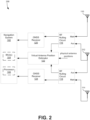
- FIG. 2 depicts a block diagram of another exemplary embodiment of a GNSS interference mitigation system.
- System 200 including each of its components, functions similarly to their counterparts shown and described with respect to Figure 1 , with some differences as further described.
- system 200 includes three antennas 110, 114, and 212 coupled to two RF nulling circuits 116, 118.
- Antenna 110 is coupled only to RF nulling circuit 116 and feeds RF signals received from a GNSS system to the main port of RF nulling circuit 116.
- antenna 114 is coupled only to RF nulling circuit 118 and feeds RF signals received from a GNSS system to the main port of RF nulling circuit 118.
- Both RF nulling circuits 116, 118 share a common antenna 212 that feeds RF signals to the auxiliary ports of both nulling circuits.
- the RF signals from antenna 110 are output from RF nulling circuit 116 to GNSS receiver 120 and the RF signals from antenna 114 are output from RF nulling circuit 118 to GNSS receiver 124.
- the RF signals from antenna 212 are combined at both RF nulling circuits 116, 118 with the RF signals from respective antennas 110, 114.
- the phase shift configuration data from the combined signals from antennas 110 and 212 are output from RF nulling circuit 116 to virtual antenna position estimator 122.
- the phase shift configuration data from the combined signals from antennas 114 and 212 are output from RF nulling circuit 118 to virtual antenna position estimator 122.
- the phase shift configuration data is used by the virtual antenna position estimator 122 to determine the virtual positions of each RF output of RF nulling circuit 116, 118, and provides the virtual positions to navigation system 102 for determining navigation parameters of the vehicle.
- navigation system 102 operates as a dual receiver heading functionality system that is configured to determine a heading of the vehicle based on the GNSS information provided by GNSS receivers 120, 124 and the virtual antenna positions of each RF output of RF nulling circuit. For example, navigation system 102 calculates the heading of the vehicle using the GNSS information supplied by each GNSS receiver 120, 124 and the difference in the virtual antenna position between each antenna. The use of these virtual antenna positions provides a check in the event that GNSS interference is present. Specifically, when GNSS interference is present, the virtual antenna positions determined from the phase shift configuration data may be different than the known physical antenna positions on the vehicle. To compensate for effects from GNSS interference, navigation system 102 uses the computed virtual antenna positions instead of the known physical antenna positions when determining the heading of the vehicle.
- Figure 3 depicts another exemplary embodiment of a GNSS interference mitigation system 300.
- System 300 including each of its components, functions similarly to their counterparts shown and described with respect to Figures 2-3 , with some differences as further described.
- system 300 includes four antennas 110, 114, 212, 313 coupled to two RF nulling circuits 116, 118.
- each RF nulling circuit is coupled to different antennas.
- RF nulling circuit 116 is coupled to antennas 110 and 212, while RF nulling circuit 118 is coupled to antennas 114 and 313.
- antenna 110 provides RF signals to the main port of RF nulling circuit 116 and antenna 212 provides RF signals to the auxiliary port of RF nulling circuit 116. While no GNSS interference is present, only the RF signals from antenna 110 are provided to GNSS receiver 120. However, in the presence of GNSS interference, RF nulling circuit 116 outputs a combination of the RF signals from antenna 110 and antenna 212.
- RF nulling circuit 118 operates in a similar fashion, in which antenna 114 provides RF signals to the main port while antenna 313 provides RF signals to the auxiliary port.
- each GNSS receiver 120, 124 outputs GNSS information specific to different antennas, the effects from GNSS interference can be more easily compensated for when determining the heading of the vehicle or other navigation parameters. Additionally, the use of additional antennas provides redundancy in the case of a fault or malfunction in the system 300.
- Figures 1-3 depicts embodiments of two to four antennas, any plurality of antennas can be used. For example, more than four antennas can be used to provide additional data redundancy to improve the accuracy of GNSS information provided to navigation system 102. In some embodiments, additional GNSS receivers and RF nulling circuits can also be used.
- Figure 4 depicts a flow diagram of a method 400 for operating a GNSS interference mitigation system.
- Method 400 may be implemented via the techniques described with respect to Figures 1-3 , but may be implemented via other techniques as well.
- the blocks of the flow diagram have been arranged in a generally sequential manner for ease of explanation; however, it is to be understood that this arrangement is merely exemplary, and it should be recognized that the processing associated with the methods described herein (and the blocks shown in the Figures) may occur in a different order (for example, where at least some of the processing associated with the blocks is performed in parallel and/or in an event-driven manner).
- Method 400 includes receiving RF signals from each of a plurality of antennas at block 402.
- Each antenna is configured for receiving GNSS signals from a GNSS system. However, when GNSS interference is present, the antennas may receive other RF signals that do not originate from a GNSS system.
- Method 400 also receives the physical antenna positions of each of the plurality of antennas at block 404. Such information can be stored in memory and accessible by a virtual position antenna estimator as described in Figures 1-3 .
- method 400 receives phase shift configuration data of the RF signals acquired from each of the plurality of antennas. The phase shift configuration data is determined by combining the RF signals received from different antennas at different ports of an RF nulling circuit.
- the phase shift configuration data can also be received from multiple RF nulling circuits.
- the RF nulling circuits are coupled to the same antennas, as shown in Figure 1 ; however, in other embodiments, the RF nulling circuits are coupled to different antennas.
- the RF nulling circuit can be coupled to a shared antenna, as shown in Figure 2 .
- Each RF nulling circuit is configured to reduce the effects of GNSS interference by combining the RF signals of different antennas.
- Method 400 proceeds to block 408 and determines the virtual antenna position of each RF output of the plurality of RF nulling circuits.
- the virtual antenna position for a given RF output of an RF nulling circuit is determined from the physical antenna positions and the phase shift configuration data corresponding to the antenna. During periods of GNSS interference, the virtual antenna positions will likely depart from the known physical antenna positions on the vehicle.
- method 400 provides the GNSS information associated with the RF signals received from each RF nulling circuit as well as the virtual antenna positions to a navigation system at block 410.
- the navigation system comprises at least one IMU or other inertial sensors, as well as processing circuitry.
- method 400 proceeds to block 412 and determines one or more navigation parameters based on the virtual antenna positions and GNSS information provided in block 410.
- the navigation system can use the GNSS information along with inertial data from inertial sensors to determine navigation parameters.
- the navigation system utilizes the virtual antenna positions and the GNSS information to determine a heading of the vehicle. By utilizing virtual antenna positions, the navigation system can determine the heading of the vehicle using GNSS information even during periods in which GNSS interference is present.
- the methods and techniques described herein may be implemented at least in part in digital electronic circuitry, or with a programmable processor (for example, a special-purpose processor or a general-purpose processor such as a computer) firmware, software, or in various combinations of each.
- Apparatus embodying these techniques may include appropriate input and output devices, a programmable processor, and a storage medium tangibly embodying program instructions for execution by the programmable processor.
- a process embodying these techniques may be performed by a programmable processor executing a program of instructions to perform desired functions by operating on input data and generating appropriate output.
- the techniques may advantageously be implemented in one or more programs that are executable on a programmable system including at least one programmable processor coupled to receive data and instructions from, and to transmit data and instruction to, a data storage system, at least one input device, and at least one output device.
- a processor will receive instructions and data from a read-only memory and/or a random-access memory.
- Storage devices suitable for tangibly embodying computer program instructions and data include all forms of non-volatile memory, including by way of example semiconductor memory devices, such as erasable programmable read-only memory (EPROM), electrically-erasable programmable read-only memory (EEPROM), and flash memory devices; magnetic disks such as internal hard disks and removable disks; magneto-optical disks; and the like. Any of the foregoing may be supplemented by, or incorporated in, specially-designed application specific integrated circuits (ASICs).
- ASICs application specific integrated circuits
- Example 1 includes a system, comprising: at least two antennas, each of the at least two antennas configured for receiving Global Navigation Satellite System (GNSS) signals; a first radio frequency (RF) nulling circuit having a main port coupled to a first antenna of the at least two antennas and an auxiliary port coupled to a first auxiliary antenna of the at least two antennas; a second RF nulling circuit having a main port coupled to a second antenna of the at least two antennas and an auxiliary port coupled a second auxiliary antenna of the at least two antennas, a first GNSS receiver coupled to an output of the first RF nulling circuit; a second GNSS receiver coupled to an output of the second RF nulling circuit; a navigation system coupled to an output of the first GNSS receiver and an output of the second GNSS receiver; and a virtual antenna position estimator coupled to the navigation system and coupled to receive phase shift configuration data from the first RF nulling circuit and the second RF nulling circuit, wherein the virtual antenna position estimator calculates virtual antenna positions based on the
- Example 2 includes the system of Example 1, wherein only two antennas are coupled to the first RF nulling circuit and the second RF nulling circuit, wherein the first auxiliary antenna coupled to the first RF nulling circuit is the second antenna, wherein the second auxiliary antenna coupled to the second RF nulling circuit is the first antenna.
- Example 3 includes the system of any of Examples 1-2, wherein the at least two antennas comprises three antennas, wherein the first auxiliary antenna is the second auxiliary antenna.
- Example 4 includes the system of any of Examples 1-3, wherein the at least two antennas comprises four antennas, wherein the first auxiliary antenna is distinct from the second auxiliary antenna.
- Example 5 includes the system of any of Examples 1-4, wherein the at least one navigation parameter includes a heading of a vehicle, wherein the navigation system utilizes the virtual antenna positions for GNSS heading functions performed by the navigation system.
- Example 6 includes the system of any of Examples 1-5, wherein when no GNSS interference is detected, the first and second RF nulling circuit is configured to respectively output RF signals from the first and the second antenna to the respective first and the second GNSS receiver, wherein when GNSS interference is detected, the first RF nulling circuit is configured to output a combined RF signal from the first antenna and the first auxiliary antenna to the first GNSS receiver, wherein when GNSS interference is detected, the second RF nulling circuit is configured to output a combined RF signal from the second antenna and the second auxiliary antenna to the second GNSS receiver.
- Example 7 includes the system of any of Examples 1-6, wherein the first GNSS receiver is configured to determine first GNSS information from RF signals received from the output of the first RF nulling circuit, wherein the second GNSS receiver is configured to determine second GNSS information from the RF signals received from the output of the second RF nulling circuit, wherein the navigation system is configured to determine the at least one navigation parameter based on the first and second GNSS information.
- Example 8 includes the system of any of Examples 1-7, wherein the phase shift configuration data includes a phase shift between an RF signal received at the main port and an RF signal received at the auxiliary port.
- Example 9 includes the system of any of Examples 1-8, wherein the first and second RF nulling circuit is configured to attenuate RF signals associated with GNSS interference.
- Example 10 includes a method, comprising: receiving radio frequency (RF) signals from each of a plurality of antennas coupled to a vehicle, wherein each antenna is configured to receive signals from a Global Navigation Satellite System (GNSS); receiving a physical antenna position of each of the plurality of antennas; receiving phase shift configuration data of the RF signals from an output of each of a plurality of RF nulling circuits; determining virtual antenna positions corresponding to the output of each of the plurality of RF nulling circuits based on the physical antenna positions and the respective phase shift configuration data from each of the RF nulling circuits; and providing GNSS information derived from the RF signals and the virtual antenna positions to a navigation system.
- RF radio frequency
- Example 11 includes the method of Example 10, comprising: determining at least one navigation parameter based on the virtual antenna positions and the GNSS information.
- Example 12 includes the method of any of Examples 10-11, wherein the plurality of antennas comprises a first antenna and a second antenna, wherein the first antenna is coupled to a main port of a first RF nulling circuit and to an auxiliary port of a second RF nulling circuit, wherein the second antenna is coupled to a main port of a second RF nulling circuit and to an auxiliary port of the first RF nulling circuit, wherein determining phase shift configuration data comprises determining a phase shift between RF signals received from the first antenna and RF signals received from the second antenna.
- Example 13 includes the method of any of Examples 10-12, wherein the plurality of antennas comprises a first antenna, a second antenna, and a third antenna, wherein the first antenna is coupled to a main port of a first RF nulling circuit, wherein the second antenna is coupled to a main port of a second RF nulling circuit, wherein the third antenna is coupled to an auxiliary port of the first RF nulling circuit and to an auxiliary port of the second RF nulling circuit, wherein determining phase shift configuration data comprises determining a first phase shift between RF signals received from the first antenna and RF signals received from the third antenna, and determining a second phase shift between RF signals received from the second antenna and the RF signals received from the third antenna.
- Example 14 includes the method of any of Examples 10-13, wherein the plurality of antennas comprises a first antenna, a second antenna, a third antenna, and a fourth antenna, wherein the first antenna is coupled to a main port of a first RF nulling circuit, wherein the second antenna is coupled to an auxiliary port of the first RF nulling circuit, wherein the third antenna is coupled to a main port of a second RF nulling circuit, wherein the fourth antenna is coupled to an auxiliary port of the second RF nulling circuit, wherein determining phase shift configuration data comprises determining a first phase shift between RF signals received from the first antenna and RF signals received from the second antenna, and determining a second phase shift between RF signals received from the third antenna and RF signals received from the fourth antenna.
- Example 15 includes the method of any of Examples 11-14, wherein the at least one navigation parameter includes a heading of the vehicle, wherein determining the at least one navigation parameter comprises utilizing the virtual antenna positions in performing GNSS heading functions by a navigation system.
- Example 16 includes the method of any of Examples 10-15, wherein the plurality of antennas comprises a first antenna, a second antenna, a first auxiliary antenna, and a second auxiliary antenna, comprising: outputting RF signals from the first antenna to a first GNSS receiver when no GNSS interference is present, outputting RF signals from the second antenna to a second GNSS receiver when no GNSS interference is present, outputting combined RF signals from the first antenna and the first auxiliary antenna to the first GNSS receiver when GNSS interference is present, and outputting combined RF signals from the second antenna and the second auxiliary antenna to the second GNSS receiver when GNSS interference is present.
- Example 17 includes the method of any of Examples 10-16, wherein the plurality of antennas comprises a first antenna and a second antenna, and comprising: determining first GNSS information from RF signals received from the first antenna; determining second GNSS information from RF signals received from the second antenna; and determining at least one navigation parameter based on the first GNSS information and the second GNSS information.
- Example 18 includes the method of any of Examples 10-17, comprising attenuating RF signals associated with GNSS interference received from at least one of the plurality of antennas.
- Example 19 includes a program product comprising a non-transitory processor-readable medium on which program instructions configured to be executed by at least one processor are embodied, wherein by executing the program instructions, the at least one processor is configured to: receive radio frequency (RF) signals from each of a plurality of antennas coupled to a vehicle, wherein each antenna is configured to receive signals from a Global Navigation Satellite System (GNSS); receive a physical antenna position of each of the plurality of antennas; receive phase shift configuration data of the RF signals acquired from each of the plurality of antennas from an output of each of a plurality of RF nulling circuits; determine virtual antenna positions corresponding to the output of each of the plurality of RF nulling circuits based on the physical antenna positions and the respective phase shift configuration data from each of the RF nulling circuits; and provide GNSS information derived from the RF signals and the virtual antenna positions to a navigation system.
- RF radio frequency
- GNSS Global Navigation Satellite System
- Example 20 includes the program product of Example 19, wherein the at least one processor is configured to determine at least one navigation parameter based on the virtual antenna positions and the GNSS information.
Landscapes
- Engineering & Computer Science (AREA)
- Radar, Positioning & Navigation (AREA)
- Remote Sensing (AREA)
- Computer Networks & Wireless Communication (AREA)
- Physics & Mathematics (AREA)
- General Physics & Mathematics (AREA)
- Signal Processing (AREA)
- Position Fixing By Use Of Radio Waves (AREA)
Abstract
Embodiments are directed to improving blended GNSS/inertial navigation system tolerance to external GNSS interference. A plurality of RF nulling circuits is coupled to at least two antennas and to the inputs of dual GNSS-receivers. The RF nulling circuits provide phase shift configuration data from RF signals input from the antennas to a virtual antenna position estimator. The virtual antenna position estimator determines virtual antenna positions based on the physical antenna position and the phase shift configuration data from each RF nulling circuit. The virtual antenna position estimator then provides the virtual antenna positions to a navigation system for determining at least one navigation parameter of the vehicle.
Description
- In an increasingly globalized economy, vehicles such as aircraft serve as the conduit for facilitating global commerce. In order to safely navigate through various environments and coordinate effective travel routes, vehicles rely on Global Navigation Satellite System (GNSS) aided navigation technology. These systems facilitate fast and accurate determination of position information, such as lateral position and altitude, to the vehicle via a GNSS receiver. Some systems on the vehicle may also rely on GNSS information to enhance or supplement the functionality supported by a given system.
- However, utilizing GNSS technology does not come without risks. For instance, a radio frequency (RF)-emitting source may broadcast signals that render GNSS equipment inoperable (known as GNSS "jamming"), or may feed false signals to the GNSS equipment that causes the equipment to receive the false signals instead of the true signals sent by GNSS satellites (known as GNSS "spoofing"). GNSS jamming and GNSS spoofing are examples of GNSS interference, which adversely impact GNSS equipment during navigation and may lead to a wide variety of serious and potentially consequences, most notably the high risk of crash. When GNSS interference is present, systems that utilize GNSS information ordinarily cannot function as reliable navigation tools.
- Therefore, a need exists to enable continuous and accurate GNSS navigation functionality even when GNSS interference is present.
- The details of one or more embodiments are set forth in the description below. The features illustrated or described in connection with one exemplary embodiment may be combined with the features of other embodiments. Thus, any of the various embodiments described herein can be combined to provide further embodiments. Aspects of the embodiments can be modified, if necessary to employ concepts of the various patents, applications and publications as identified herein to provide yet further embodiments.
- In one embodiment, a system is disclosed. The system comprises at least two antennas. Each of the at least two antennas is configured for receiving Global Navigation Satellite System (GNSS) signals. The system comprises a first radio frequency (RF) nulling circuit having a main port coupled to a first antenna of the at least two antennas and an auxiliary port coupled to a first auxiliary antenna of the at least two antennas. The system comprises a second RF nulling circuit having a main port coupled to a second antenna of the at least two antennas and an auxiliary port coupled a second auxiliary antenna of the at least two antennas. The system comprises a first GNSS receiver coupled to an output of the first RF nulling circuit, and a second GNSS receiver coupled to an output of the second RF nulling circuit. The system comprises a navigation system coupled to an output of the first GNSS receiver and an output of the second GNSS receiver. The system comprises a virtual antenna position estimator coupled to the navigation system and coupled to receive phase shift configuration data from the first RF nulling circuit and the second RF nulling circuit. The virtual antenna position estimator is configured to calculate virtual antenna positions based on the phase shift configuration data and physical positions of the at least two antennas. The virtual antenna position estimator is configured to provide the virtual antenna positions to the navigation system. The navigation system is configured to determine at least one navigation parameter based on the virtual antenna positions.
- In another embodiment a method is disclosed. The method comprises receiving radio frequency (RF) signals from each of a plurality of antennas coupled to a vehicle. Each antenna is configured to receive signals from a Global Navigation Satellite System (GNSS). The method comprises receiving a physical antenna position of each of the plurality of antennas. The method comprises receiving phase shift configuration data of the RF signals acquired from each of the plurality of antennas from an output of each of a plurality of RF nulling circuits. The method comprises determining virtual antenna positions corresponding to the output of each of the plurality of RF nulling circuits based on the physical antenna positions and the respective phase shift configuration data from each of the RF nulling circuits. The method comprises providing GNSS information derived from the RF signals and the virtual antenna positions to a navigation system.
- In yet another embodiment, a program product is disclosed. The program product comprises a non-transitory processor-readable medium on which program instructions configured to be executed by at least one processor are embodied. By executing the program instructions, the at least one processor is configured to receive radio frequency (RF) signals from each of a plurality of antennas coupled to a vehicle. Each antenna is configured to receive signals from a Global Navigation Satellite System (GNSS). The at least one processor is configured to receive a physical antenna position of each of the plurality of antennas. The at least one processor is configured to receive phase shift configuration data of the RF signals acquired from each of the plurality of antennas from an output of each of a plurality of RF nulling circuits. The at least one processor is configured to determine virtual antenna positions corresponding to the output of each of the plurality of RF nulling circuits based on the physical antenna positions and the respective phase shift configuration data from each of the RF nulling circuits. The at least one processor is configured to provide GNSS information derived from the RF signals and the virtual antenna positions to a navigation system.
- Additional embodiments are disclosed, as subsequently described.
- Understanding that the drawings depict only exemplary embodiments and are not therefore to be considered limiting in scope, the exemplary embodiments will be described with additional specificity and detail through the use of the accompanying drawings, as briefly summarized below and as further described in the detailed description.
-
Figure 1 depicts a block diagram of a system including a dual GNSS receiver configuration coupled to two antennas, as described in one or more embodiments. -
Figure 2 depicts a block diagram of a system including a dual GNSS receiver configuration coupled to three antennas, as described in one or more embodiments. -
Figure 3 depicts a block diagram of a system including a dual GNSS receiver configuration coupled to four antennas, as described in one or more embodiments. -
Figure 4 depicts a flow diagram of a method for operating a GNSS interference mitigation system, as described in one or more embodiments. - In accordance with common practice, the various described features are not drawn to scale but are drawn to emphasize specific features relevant to the exemplary embodiments.
- In the following detailed description, reference is made to the accompanying drawings that form a part hereof, and in which is shown by way of illustration specific illustrative embodiments. However, it is to be understood that other embodiments may be utilized and that logical, mechanical, and electrical changes may be made. Furthermore, the method presented in the drawing figures and the specification is not to be construed as limiting the order in which the individual steps may be performed. The following detailed description is, therefore, not to be taken in a limiting sense.
-
Figure 1 depicts a block diagram of an exemplary GNSS interference mitigation system ("system") 100 in which the GNSS interference mitigation techniques described herein can be utilized.System 100 is configured to be coupled to a vehicle (not shown inFigure 1 ). For example,system 100 can be mounted on the exterior or interior portions of the vehicle, and can be coupled to other systems on the vehicle not explicitly shown inFigure 1 . In some embodiments,system 100 is distributed on different portions of the vehicle, which can be electrically coupled together through a communication bus or other suitable interface. Use of the term "vehicle" is not intended to be limiting and includes all classes of vehicles falling within the ordinary meaning of the term. This would include but not limited to aerial traversing vehicles, water traversing vehicles, and land traversing vehicles. Throughout the disclosure, the vehicle may be further illustrated as an aircraft with the understanding that the principles described herein apply to other vehicles where applicable. - In the embodiment of
Figure 1 ,system 100 includes a dual antenna configuration with twoantennas Figures 2-3 , additional antennas may be included in the system. Eachantenna -
System 100 further includes twoRF nulling circuits antennas RF nulling circuit antennas RF nulling circuit antennas Figure 1 , the main port ofRF nulling circuit 116 receives the GNSS signals fromantenna 110 while the auxiliary port ofRF nulling circuit 116 receives the GNSS signals fromantenna 114. The main port ofRF nulling circuit 118 receives the GNSS signals fromantenna 114 while the auxiliary port ofRF nulling circuit 118 receives the GNSS signals fromantenna 110. When no GNSS interference is present, each RF nulling circuit operates in a normal/bypass mode in which the GNSS signals received at the main port are output to the respective GNSS receiver. Referring toFigure 1 ,RF nulling circuit 116 outputs the GNSS signals fromantenna 110 toGNSS receiver 120 during normal mode operation, andRF nulling circuit 118 outputs the GNSS signals fromantenna 114 toGNSS receiver 124. While operating in a normal mode, the RF signals from the auxiliary ports are not output to theGNSS receivers RF nulling circuit - Each
RF nulling circuit respective GNSS receiver GNSS receiver RF nulling circuits GNSS receiver RF nulling circuit GNSS receiver respective antennas navigation system 102. -
System 100 includes a virtualantenna position estimator 122 coupled to bothRF nulling circuits antenna position estimator 122 receives or determines the physical positions ofantennas antenna position estimator 122 from another system coupled to the vehicle (not shown inFigure 1 ). In some embodiments, virtualantenna position estimator 122 stores the physical antenna positions ofantennas antenna position estimator 122 receives the phase shift configuration data from eachRF nulling circuit antennas antenna position estimator 122. - Virtual
antenna position estimator 122 is configured to determine the virtual antenna positions of each RF output ofRF nulling circuits RF nulling circuit antenna GNSS receiver -
System 100 further includesnavigation system 102 coupled to eachGNSS receiver antenna position estimator 122.Navigation system 102 receives the GNSS information (e.g., pseudoranges, carrier phase, and position information) determined fromGNSS receivers RF nulling circuits antenna position estimator 122.Navigation system 102 uses the virtual antenna positions and the GNSS information fromGNSS receivers navigation system 102 with the GNSS information provided fromGNSS receivers antenna position estimator 122. TheIMU 104 in some embodiments comprises one or more gyroscopes, one or more accelerometers, and optionally one or more magnetometers. Additionally,navigation system 102 may include at least oneprocessor 106 that uses the GNSS information for performing navigation functions for the vehicle, including calculating navigation parameters such as position, velocity, heading, and the like. -
Processor 106, or any of the processing systems included in system 100 (e.g., the processing functions performed byGNSS receivers -
System 100 acts as a GNSS-enhanced navigation system that blends GNSS-acquired information with non-GNSS information to determine navigation parameters of the vehicle. Generally, GNSS interference risks inoperability or use of inaccurate information for these blended systems. However,system 100 can utilize GNSS functionality even when GNSS interference is present. Accordingly,system 100 can implement accurate GNSS functionality that is uninterrupted by GNSS interference. -
Figure 2 depicts a block diagram of another exemplary embodiment of a GNSS interference mitigation system.System 200, including each of its components, functions similarly to their counterparts shown and described with respect toFigure 1 , with some differences as further described. In the embodiment ofFigure 2 ,system 200 includes threeantennas RF nulling circuits Antenna 110 is coupled only toRF nulling circuit 116 and feeds RF signals received from a GNSS system to the main port ofRF nulling circuit 116. In similar fashion,antenna 114 is coupled only toRF nulling circuit 118 and feeds RF signals received from a GNSS system to the main port ofRF nulling circuit 118. BothRF nulling circuits common antenna 212 that feeds RF signals to the auxiliary ports of both nulling circuits. - When no GNSS interference is present, the RF signals from
antenna 110 are output fromRF nulling circuit 116 toGNSS receiver 120 and the RF signals fromantenna 114 are output fromRF nulling circuit 118 toGNSS receiver 124. When GNSS interference is detected, the RF signals fromantenna 212 are combined at bothRF nulling circuits respective antennas antennas RF nulling circuit 116 to virtualantenna position estimator 122. Likewise, the phase shift configuration data from the combined signals fromantennas RF nulling circuit 118 to virtualantenna position estimator 122. The phase shift configuration data is used by the virtualantenna position estimator 122 to determine the virtual positions of each RF output ofRF nulling circuit navigation system 102 for determining navigation parameters of the vehicle. - In some embodiments,
navigation system 102 operates as a dual receiver heading functionality system that is configured to determine a heading of the vehicle based on the GNSS information provided byGNSS receivers navigation system 102 calculates the heading of the vehicle using the GNSS information supplied by eachGNSS receiver navigation system 102 uses the computed virtual antenna positions instead of the known physical antenna positions when determining the heading of the vehicle. -
Figure 3 depicts another exemplary embodiment of a GNSSinterference mitigation system 300.System 300, including each of its components, functions similarly to their counterparts shown and described with respect toFigures 2-3 , with some differences as further described. In the embodiment ofFigure 3 ,system 300 includes fourantennas RF nulling circuits RF nulling circuit 116 is coupled toantennas RF nulling circuit 118 is coupled toantennas RF nulling circuit 116,antenna 110 provides RF signals to the main port ofRF nulling circuit 116 andantenna 212 provides RF signals to the auxiliary port ofRF nulling circuit 116. While no GNSS interference is present, only the RF signals fromantenna 110 are provided toGNSS receiver 120. However, in the presence of GNSS interference,RF nulling circuit 116 outputs a combination of the RF signals fromantenna 110 andantenna 212.RF nulling circuit 118 operates in a similar fashion, in whichantenna 114 provides RF signals to the main port whileantenna 313 provides RF signals to the auxiliary port. - Because each
GNSS receiver system 300. AlthoughFigures 1-3 depicts embodiments of two to four antennas, any plurality of antennas can be used. For example, more than four antennas can be used to provide additional data redundancy to improve the accuracy of GNSS information provided tonavigation system 102. In some embodiments, additional GNSS receivers and RF nulling circuits can also be used. -
Figure 4 depicts a flow diagram of amethod 400 for operating a GNSS interference mitigation system.Method 400 may be implemented via the techniques described with respect toFigures 1-3 , but may be implemented via other techniques as well. The blocks of the flow diagram have been arranged in a generally sequential manner for ease of explanation; however, it is to be understood that this arrangement is merely exemplary, and it should be recognized that the processing associated with the methods described herein (and the blocks shown in the Figures) may occur in a different order (for example, where at least some of the processing associated with the blocks is performed in parallel and/or in an event-driven manner). -
Method 400 includes receiving RF signals from each of a plurality of antennas atblock 402. Each antenna is configured for receiving GNSS signals from a GNSS system. However, when GNSS interference is present, the antennas may receive other RF signals that do not originate from a GNSS system.Method 400 also receives the physical antenna positions of each of the plurality of antennas atblock 404. Such information can be stored in memory and accessible by a virtual position antenna estimator as described inFigures 1-3 . Atblock 406,method 400 receives phase shift configuration data of the RF signals acquired from each of the plurality of antennas. The phase shift configuration data is determined by combining the RF signals received from different antennas at different ports of an RF nulling circuit. The phase shift configuration data can also be received from multiple RF nulling circuits. In some embodiments, the RF nulling circuits are coupled to the same antennas, as shown inFigure 1 ; however, in other embodiments, the RF nulling circuits are coupled to different antennas. In these embodiments, the RF nulling circuit can be coupled to a shared antenna, as shown inFigure 2 . Each RF nulling circuit is configured to reduce the effects of GNSS interference by combining the RF signals of different antennas. -
Method 400 proceeds to block 408 and determines the virtual antenna position of each RF output of the plurality of RF nulling circuits. The virtual antenna position for a given RF output of an RF nulling circuit is determined from the physical antenna positions and the phase shift configuration data corresponding to the antenna. During periods of GNSS interference, the virtual antenna positions will likely depart from the known physical antenna positions on the vehicle. To better compensate for GNSS interference,method 400 provides the GNSS information associated with the RF signals received from each RF nulling circuit as well as the virtual antenna positions to a navigation system atblock 410. In some embodiments, the navigation system comprises at least one IMU or other inertial sensors, as well as processing circuitry. - Optionally,
method 400 proceeds to block 412 and determines one or more navigation parameters based on the virtual antenna positions and GNSS information provided inblock 410. The navigation system can use the GNSS information along with inertial data from inertial sensors to determine navigation parameters. For example, the navigation system utilizes the virtual antenna positions and the GNSS information to determine a heading of the vehicle. By utilizing virtual antenna positions, the navigation system can determine the heading of the vehicle using GNSS information even during periods in which GNSS interference is present. - The methods and techniques described herein may be implemented at least in part in digital electronic circuitry, or with a programmable processor (for example, a special-purpose processor or a general-purpose processor such as a computer) firmware, software, or in various combinations of each. Apparatus embodying these techniques may include appropriate input and output devices, a programmable processor, and a storage medium tangibly embodying program instructions for execution by the programmable processor. A process embodying these techniques may be performed by a programmable processor executing a program of instructions to perform desired functions by operating on input data and generating appropriate output. The techniques may advantageously be implemented in one or more programs that are executable on a programmable system including at least one programmable processor coupled to receive data and instructions from, and to transmit data and instruction to, a data storage system, at least one input device, and at least one output device. Generally, a processor will receive instructions and data from a read-only memory and/or a random-access memory. Storage devices suitable for tangibly embodying computer program instructions and data include all forms of non-volatile memory, including by way of example semiconductor memory devices, such as erasable programmable read-only memory (EPROM), electrically-erasable programmable read-only memory (EEPROM), and flash memory devices; magnetic disks such as internal hard disks and removable disks; magneto-optical disks; and the like. Any of the foregoing may be supplemented by, or incorporated in, specially-designed application specific integrated circuits (ASICs).
- Example 1 includes a system, comprising: at least two antennas, each of the at least two antennas configured for receiving Global Navigation Satellite System (GNSS) signals; a first radio frequency (RF) nulling circuit having a main port coupled to a first antenna of the at least two antennas and an auxiliary port coupled to a first auxiliary antenna of the at least two antennas; a second RF nulling circuit having a main port coupled to a second antenna of the at least two antennas and an auxiliary port coupled a second auxiliary antenna of the at least two antennas, a first GNSS receiver coupled to an output of the first RF nulling circuit; a second GNSS receiver coupled to an output of the second RF nulling circuit; a navigation system coupled to an output of the first GNSS receiver and an output of the second GNSS receiver; and a virtual antenna position estimator coupled to the navigation system and coupled to receive phase shift configuration data from the first RF nulling circuit and the second RF nulling circuit, wherein the virtual antenna position estimator calculates virtual antenna positions based on the phase shift configuration data and physical positions of the at least two antennas and provides the virtual antenna positions to the navigation system, wherein the navigation system determines at least one navigation parameter based on the virtual antenna positions.
- Example 2 includes the system of Example 1, wherein only two antennas are coupled to the first RF nulling circuit and the second RF nulling circuit, wherein the first auxiliary antenna coupled to the first RF nulling circuit is the second antenna, wherein the second auxiliary antenna coupled to the second RF nulling circuit is the first antenna.
- Example 3 includes the system of any of Examples 1-2, wherein the at least two antennas comprises three antennas, wherein the first auxiliary antenna is the second auxiliary antenna.
- Example 4 includes the system of any of Examples 1-3, wherein the at least two antennas comprises four antennas, wherein the first auxiliary antenna is distinct from the second auxiliary antenna.
- Example 5 includes the system of any of Examples 1-4, wherein the at least one navigation parameter includes a heading of a vehicle, wherein the navigation system utilizes the virtual antenna positions for GNSS heading functions performed by the navigation system.
- Example 6 includes the system of any of Examples 1-5, wherein when no GNSS interference is detected, the first and second RF nulling circuit is configured to respectively output RF signals from the first and the second antenna to the respective first and the second GNSS receiver, wherein when GNSS interference is detected, the first RF nulling circuit is configured to output a combined RF signal from the first antenna and the first auxiliary antenna to the first GNSS receiver, wherein when GNSS interference is detected, the second RF nulling circuit is configured to output a combined RF signal from the second antenna and the second auxiliary antenna to the second GNSS receiver.
- Example 7 includes the system of any of Examples 1-6, wherein the first GNSS receiver is configured to determine first GNSS information from RF signals received from the output of the first RF nulling circuit, wherein the second GNSS receiver is configured to determine second GNSS information from the RF signals received from the output of the second RF nulling circuit, wherein the navigation system is configured to determine the at least one navigation parameter based on the first and second GNSS information.
- Example 8 includes the system of any of Examples 1-7, wherein the phase shift configuration data includes a phase shift between an RF signal received at the main port and an RF signal received at the auxiliary port.
- Example 9 includes the system of any of Examples 1-8, wherein the first and second RF nulling circuit is configured to attenuate RF signals associated with GNSS interference.
- Example 10 includes a method, comprising: receiving radio frequency (RF) signals from each of a plurality of antennas coupled to a vehicle, wherein each antenna is configured to receive signals from a Global Navigation Satellite System (GNSS); receiving a physical antenna position of each of the plurality of antennas; receiving phase shift configuration data of the RF signals from an output of each of a plurality of RF nulling circuits; determining virtual antenna positions corresponding to the output of each of the plurality of RF nulling circuits based on the physical antenna positions and the respective phase shift configuration data from each of the RF nulling circuits; and providing GNSS information derived from the RF signals and the virtual antenna positions to a navigation system.
- Example 11 includes the method of Example 10, comprising: determining at least one navigation parameter based on the virtual antenna positions and the GNSS information.
- Example 12 includes the method of any of Examples 10-11, wherein the plurality of antennas comprises a first antenna and a second antenna, wherein the first antenna is coupled to a main port of a first RF nulling circuit and to an auxiliary port of a second RF nulling circuit, wherein the second antenna is coupled to a main port of a second RF nulling circuit and to an auxiliary port of the first RF nulling circuit, wherein determining phase shift configuration data comprises determining a phase shift between RF signals received from the first antenna and RF signals received from the second antenna.
- Example 13 includes the method of any of Examples 10-12, wherein the plurality of antennas comprises a first antenna, a second antenna, and a third antenna, wherein the first antenna is coupled to a main port of a first RF nulling circuit, wherein the second antenna is coupled to a main port of a second RF nulling circuit, wherein the third antenna is coupled to an auxiliary port of the first RF nulling circuit and to an auxiliary port of the second RF nulling circuit, wherein determining phase shift configuration data comprises determining a first phase shift between RF signals received from the first antenna and RF signals received from the third antenna, and determining a second phase shift between RF signals received from the second antenna and the RF signals received from the third antenna.
- Example 14 includes the method of any of Examples 10-13, wherein the plurality of antennas comprises a first antenna, a second antenna, a third antenna, and a fourth antenna, wherein the first antenna is coupled to a main port of a first RF nulling circuit, wherein the second antenna is coupled to an auxiliary port of the first RF nulling circuit, wherein the third antenna is coupled to a main port of a second RF nulling circuit, wherein the fourth antenna is coupled to an auxiliary port of the second RF nulling circuit, wherein determining phase shift configuration data comprises determining a first phase shift between RF signals received from the first antenna and RF signals received from the second antenna, and determining a second phase shift between RF signals received from the third antenna and RF signals received from the fourth antenna.
- Example 15 includes the method of any of Examples 11-14, wherein the at least one navigation parameter includes a heading of the vehicle, wherein determining the at least one navigation parameter comprises utilizing the virtual antenna positions in performing GNSS heading functions by a navigation system.
- Example 16 includes the method of any of Examples 10-15, wherein the plurality of antennas comprises a first antenna, a second antenna, a first auxiliary antenna, and a second auxiliary antenna, comprising: outputting RF signals from the first antenna to a first GNSS receiver when no GNSS interference is present, outputting RF signals from the second antenna to a second GNSS receiver when no GNSS interference is present, outputting combined RF signals from the first antenna and the first auxiliary antenna to the first GNSS receiver when GNSS interference is present, and outputting combined RF signals from the second antenna and the second auxiliary antenna to the second GNSS receiver when GNSS interference is present.
- Example 17 includes the method of any of Examples 10-16, wherein the plurality of antennas comprises a first antenna and a second antenna, and comprising: determining first GNSS information from RF signals received from the first antenna; determining second GNSS information from RF signals received from the second antenna; and determining at least one navigation parameter based on the first GNSS information and the second GNSS information.
- Example 18 includes the method of any of Examples 10-17, comprising attenuating RF signals associated with GNSS interference received from at least one of the plurality of antennas.
- Example 19 includes a program product comprising a non-transitory processor-readable medium on which program instructions configured to be executed by at least one processor are embodied, wherein by executing the program instructions, the at least one processor is configured to: receive radio frequency (RF) signals from each of a plurality of antennas coupled to a vehicle, wherein each antenna is configured to receive signals from a Global Navigation Satellite System (GNSS); receive a physical antenna position of each of the plurality of antennas; receive phase shift configuration data of the RF signals acquired from each of the plurality of antennas from an output of each of a plurality of RF nulling circuits; determine virtual antenna positions corresponding to the output of each of the plurality of RF nulling circuits based on the physical antenna positions and the respective phase shift configuration data from each of the RF nulling circuits; and provide GNSS information derived from the RF signals and the virtual antenna positions to a navigation system.
- Example 20 includes the program product of Example 19, wherein the at least one processor is configured to determine at least one navigation parameter based on the virtual antenna positions and the GNSS information.
- Although specific embodiments have been illustrated and described herein, it will be appreciated by those of ordinary skill in the art that any arrangement, which is calculated to achieve the same purpose, may be substituted for the specific embodiments shown. Therefore, it is manifestly intended that this invention be limited only by the claims and the equivalents thereof.
Claims (10)
- A system, comprising:at least two antennas, each of the at least two antennas configured for receiving Global Navigation Satellite System (GNSS) signals;a first radio frequency (RF) nulling circuit having a main port coupled to a first antenna of the at least two antennas and an auxiliary port coupled to a first auxiliary antenna of the at least two antennas;a second RF nulling circuit having a main port coupled to a second antenna of the at least two antennas and an auxiliary port coupled a second auxiliary antenna of the at least two antennas,a first GNSS receiver coupled to an output of the first RF nulling circuit;a second GNSS receiver coupled to an output of the second RF nulling circuit;a navigation system coupled to an output of the first GNSS receiver and an output of the second GNSS receiver; anda virtual antenna position estimator coupled to the navigation system and coupled to receive phase shift configuration data from the first RF nulling circuit and the second RF nulling circuit,wherein the virtual antenna position estimator calculates virtual antenna positions based on the phase shift configuration data and physical positions of the at least two antennas and provides the virtual antenna positions to the navigation system,wherein the navigation system determines at least one navigation parameter based on the virtual antenna positions.
- The system of claim 1, wherein only two antennas are coupled to the first RF nulling circuit and the second RF nulling circuit, wherein the first auxiliary antenna coupled to the first RF nulling circuit is the second antenna, wherein the second auxiliary antenna coupled to the second RF nulling circuit is the first antenna.
- The system of claim 1, wherein the at least two antennas comprises three antennas, wherein the first auxiliary antenna is the second auxiliary antenna.
- The system of claim 1, wherein the at least two antennas comprises four antennas, wherein the first auxiliary antenna is distinct from the second auxiliary antenna.
- The system of claim 1, wherein the at least one navigation parameter includes a heading of a vehicle, wherein the navigation system utilizes the virtual antenna positions for GNSS heading functions performed by the navigation system.
- The system of claim 1,wherein when no GNSS interference is detected, the first and second RF nulling circuit is configured to respectively output RF signals from the first and the second antenna to the respective first and the second GNSS receiver,wherein when GNSS interference is detected, the first RF nulling circuit is configured to output a combined RF signal from the first antenna and the first auxiliary antenna to the first GNSS receiver,wherein when GNSS interference is detected, the second RF nulling circuit is configured to output a combined RF signal from the second antenna and the second auxiliary antenna to the second GNSS receiver.
- The system of claim 1, wherein the first GNSS receiver is configured to determine first GNSS information from RF signals received from the output of the first RF nulling circuit, wherein the second GNSS receiver is configured to determine second GNSS information from the RF signals received from the output of the second RF nulling circuit,
wherein the navigation system is configured to determine the at least one navigation parameter based on the first and second GNSS information. - A method, comprising:receiving radio frequency (RF) signals from each of a plurality of antennas coupled to a vehicle, wherein each antenna is configured to receive signals from a Global Navigation Satellite System (GNSS);receiving a physical antenna position of each of the plurality of antennas;receiving phase shift configuration data of the RF signals from an output of each of a plurality of RF nulling circuits;determining virtual antenna positions corresponding to the output of each of the plurality of RF nulling circuits based on the physical antenna positions and the respective phase shift configuration data from each of the RF nulling circuits; andproviding GNSS information derived from the RF signals and the virtual antenna positions to a navigation system.
- The method of claim 8, comprising: determining at least one navigation parameter based on the virtual antenna positions and the GNSS information.
- The method of claim 8, wherein the plurality of antennas comprises a first antenna, a second antenna, and a third antenna, wherein the first antenna is coupled to a main port of a first RF nulling circuit, wherein the second antenna is coupled to a main port of a second RF nulling circuit, wherein the third antenna is coupled to an auxiliary port of the first RF nulling circuit and to an auxiliary port of the second RF nulling circuit,
wherein determining phase shift configuration data comprises determining a first phase shift between RF signals received from the first antenna and RF signals received from the third antenna, and determining a second phase shift between RF signals received from the second antenna and the RF signals received from the third antenna.
Applications Claiming Priority (1)
| Application Number | Priority Date | Filing Date | Title |
|---|---|---|---|
| US18/486,714 US20250123403A1 (en) | 2023-10-13 | 2023-10-13 | Dual gnss receiver navigation functionality system with gnss interference mitigation |
Publications (1)
| Publication Number | Publication Date |
|---|---|
| EP4538747A1 true EP4538747A1 (en) | 2025-04-16 |
Family
ID=92883215
Family Applications (1)
| Application Number | Title | Priority Date | Filing Date |
|---|---|---|---|
| EP24201222.7A Pending EP4538747A1 (en) | 2023-10-13 | 2024-09-18 | Dual gnss receiver navigation functionality system with gnss interference mitigation |
Country Status (2)
| Country | Link |
|---|---|
| US (1) | US20250123403A1 (en) |
| EP (1) | EP4538747A1 (en) |
Citations (3)
| Publication number | Priority date | Publication date | Assignee | Title |
|---|---|---|---|---|
| US6906664B2 (en) * | 2002-10-08 | 2005-06-14 | The Aerospace Corporation | Method and system using a GPS-based phased-array scheme for three-axis attitude determination |
| US7310062B1 (en) * | 2005-07-28 | 2007-12-18 | Rockwell Collins, Inc. | Dual antenna diversity method to detect GPS signal tampering |
| CN115561783A (en) * | 2022-09-13 | 2023-01-03 | 中国电子科技集团公司第五十四研究所 | Anti-interference GNSS antenna real-time phase center change compensation method |
Family Cites Families (5)
| Publication number | Priority date | Publication date | Assignee | Title |
|---|---|---|---|---|
| US20090115657A1 (en) * | 2007-11-06 | 2009-05-07 | Ann-Tzung Cheng | Gnss receiver system and related method thereof |
| US20150212211A1 (en) * | 2014-01-24 | 2015-07-30 | Qualcomm Incorporated | Methods and systems for multi-gnss operation |
| CN204068870U (en) * | 2014-09-19 | 2014-12-31 | 成都天奥信息科技有限公司 | The down-converter unit of GNSS dual system satellite navigation receiver |
| US11262458B2 (en) * | 2018-04-04 | 2022-03-01 | The Regents Of The University Of Colorado, A Body Corporate | Smart antenna module for GNSS receivers |
| US11914054B2 (en) * | 2020-09-10 | 2024-02-27 | Honeywell International S.R.O. | System and methods for estimating attitude and heading based on GNSS carrier phase measurements with assured integrity |
-
2023
- 2023-10-13 US US18/486,714 patent/US20250123403A1/en active Pending
-
2024
- 2024-09-18 EP EP24201222.7A patent/EP4538747A1/en active Pending
Patent Citations (3)
| Publication number | Priority date | Publication date | Assignee | Title |
|---|---|---|---|---|
| US6906664B2 (en) * | 2002-10-08 | 2005-06-14 | The Aerospace Corporation | Method and system using a GPS-based phased-array scheme for three-axis attitude determination |
| US7310062B1 (en) * | 2005-07-28 | 2007-12-18 | Rockwell Collins, Inc. | Dual antenna diversity method to detect GPS signal tampering |
| CN115561783A (en) * | 2022-09-13 | 2023-01-03 | 中国电子科技集团公司第五十四研究所 | Anti-interference GNSS antenna real-time phase center change compensation method |
Also Published As
| Publication number | Publication date |
|---|---|
| US20250123403A1 (en) | 2025-04-17 |
Similar Documents
| Publication | Publication Date | Title |
|---|---|---|
| US8976064B2 (en) | Systems and methods for solution separation for ground-augmented multi-constellation terminal area navigation and precision approach guidance | |
| US9341718B2 (en) | Method and system for providing integrity for hybrid attitude and true heading | |
| EP2146217B1 (en) | Integrity of differential GPS corrections in navigation devices using military type GPS receivers | |
| RU2434248C2 (en) | Air-navigation device with inertia sensors and radio-navigation receivers and air-navigation method using said elements | |
| US9927526B2 (en) | Systems and methods for position determination in GPS-denied situations | |
| CN107209269A (en) | The method and system positioned for verifying satellites | |
| US8736487B2 (en) | Method and apparatus of using height aiding from a contour table for GNSS positioning | |
| US20160313450A1 (en) | Automotive gnss real time kinematic dead reckoning receiver | |
| CN112558127B (en) | System and method for position location estimation using two or more antennas | |
| WO2013003662A2 (en) | System and method for wireless collaborative verification of global navigation satellite system measurements | |
| Shytermeja et al. | Proposed architecture for integrity monitoring of a GNSS/MEMS system with a fisheye camera in urban environment | |
| US20160084655A1 (en) | Integrity control method and merging/consolidation device comprising a plurality of processing modules | |
| CN108780157A (en) | Automotive dead reckoning with dynamic calibration and/or dynamic weighting | |
| US9817126B2 (en) | Methods for identifying whether or not a satellite has a line of sight | |
| US9784847B1 (en) | Multiple GNSS constellation tracking for a blended navigation solution | |
| US20250123403A1 (en) | Dual gnss receiver navigation functionality system with gnss interference mitigation | |
| EP3508884A1 (en) | Intelligent satellite exclusion for multipath mitigation based on line of sight | |
| WO2022201588A1 (en) | Map processing device and map processing method | |
| US9952326B2 (en) | Systems and methods for maintaining minimum operational requirements of a ground-based augmentation system | |
| Jia et al. | Fault detection and exclusion for INS/GPS/5G tightly-coupled navigation | |
| RU2368873C1 (en) | Device that assists in ground navigation of aircraft in airport | |
| WO2020110996A1 (en) | Positioning device, speed measuring device, and program | |
| CN117310756A (en) | Multi-sensor fusion positioning method and system, machine-readable storage medium | |
| US10514260B2 (en) | Integrity control method and merging/consolidation device comprising a plurality of processing modules | |
| Lin et al. | Embedded GNSS-receiver for Multi-Constellation Localization in Railway Applications |
Legal Events
| Date | Code | Title | Description |
|---|---|---|---|
| PUAI | Public reference made under article 153(3) epc to a published international application that has entered the european phase |
Free format text: ORIGINAL CODE: 0009012 |
|
| STAA | Information on the status of an ep patent application or granted ep patent |
Free format text: STATUS: THE APPLICATION HAS BEEN PUBLISHED |
|
| AK | Designated contracting states |
Kind code of ref document: A1 Designated state(s): AL AT BE BG CH CY CZ DE DK EE ES FI FR GB GR HR HU IE IS IT LI LT LU LV MC ME MK MT NL NO PL PT RO RS SE SI SK SM TR |
|
| STAA | Information on the status of an ep patent application or granted ep patent |
Free format text: STATUS: REQUEST FOR EXAMINATION WAS MADE |
|
| 17P | Request for examination filed |
Effective date: 20251016 |