EP4538736A1 - Device with steering and channel stitching for an extended bandwidth - Google Patents
Device with steering and channel stitching for an extended bandwidth Download PDFInfo
- Publication number
- EP4538736A1 EP4538736A1 EP23203273.0A EP23203273A EP4538736A1 EP 4538736 A1 EP4538736 A1 EP 4538736A1 EP 23203273 A EP23203273 A EP 23203273A EP 4538736 A1 EP4538736 A1 EP 4538736A1
- Authority
- EP
- European Patent Office
- Prior art keywords
- channel
- channel response
- frequency band
- peak
- response
- Prior art date
- Legal status (The legal status is an assumption and is not a legal conclusion. Google has not performed a legal analysis and makes no representation as to the accuracy of the status listed.)
- Pending
Links
Images




Classifications
-
- G—PHYSICS
- G01—MEASURING; TESTING
- G01S—RADIO DIRECTION-FINDING; RADIO NAVIGATION; DETERMINING DISTANCE OR VELOCITY BY USE OF RADIO WAVES; LOCATING OR PRESENCE-DETECTING BY USE OF THE REFLECTION OR RERADIATION OF RADIO WAVES; ANALOGOUS ARRANGEMENTS USING OTHER WAVES
- G01S7/00—Details of systems according to groups G01S13/00, G01S15/00, G01S17/00
- G01S7/02—Details of systems according to groups G01S13/00, G01S15/00, G01S17/00 of systems according to group G01S13/00
- G01S7/40—Means for monitoring or calibrating
- G01S7/4004—Means for monitoring or calibrating of parts of a radar system
- G01S7/4021—Means for monitoring or calibrating of parts of a radar system of receivers
-
- H—ELECTRICITY
- H04—ELECTRIC COMMUNICATION TECHNIQUE
- H04L—TRANSMISSION OF DIGITAL INFORMATION, e.g. TELEGRAPHIC COMMUNICATION
- H04L25/00—Baseband systems
- H04L25/02—Details ; arrangements for supplying electrical power along data transmission lines
- H04L25/0202—Channel estimation
- H04L25/0204—Channel estimation of multiple channels
-
- G—PHYSICS
- G01—MEASURING; TESTING
- G01S—RADIO DIRECTION-FINDING; RADIO NAVIGATION; DETERMINING DISTANCE OR VELOCITY BY USE OF RADIO WAVES; LOCATING OR PRESENCE-DETECTING BY USE OF THE REFLECTION OR RERADIATION OF RADIO WAVES; ANALOGOUS ARRANGEMENTS USING OTHER WAVES
- G01S13/00—Systems using the reflection or reradiation of radio waves, e.g. radar systems; Analogous systems using reflection or reradiation of waves whose nature or wavelength is irrelevant or unspecified
- G01S13/02—Systems using reflection of radio waves, e.g. primary radar systems; Analogous systems
- G01S13/0209—Systems with very large relative bandwidth, i.e. larger than 10 %, e.g. baseband, pulse, carrier-free, ultrawideband
-
- G—PHYSICS
- G01—MEASURING; TESTING
- G01S—RADIO DIRECTION-FINDING; RADIO NAVIGATION; DETERMINING DISTANCE OR VELOCITY BY USE OF RADIO WAVES; LOCATING OR PRESENCE-DETECTING BY USE OF THE REFLECTION OR RERADIATION OF RADIO WAVES; ANALOGOUS ARRANGEMENTS USING OTHER WAVES
- G01S13/00—Systems using the reflection or reradiation of radio waves, e.g. radar systems; Analogous systems using reflection or reradiation of waves whose nature or wavelength is irrelevant or unspecified
- G01S13/02—Systems using reflection of radio waves, e.g. primary radar systems; Analogous systems
- G01S13/06—Systems determining position data of a target
-
- G—PHYSICS
- G01—MEASURING; TESTING
- G01S—RADIO DIRECTION-FINDING; RADIO NAVIGATION; DETERMINING DISTANCE OR VELOCITY BY USE OF RADIO WAVES; LOCATING OR PRESENCE-DETECTING BY USE OF THE REFLECTION OR RERADIATION OF RADIO WAVES; ANALOGOUS ARRANGEMENTS USING OTHER WAVES
- G01S13/00—Systems using the reflection or reradiation of radio waves, e.g. radar systems; Analogous systems using reflection or reradiation of waves whose nature or wavelength is irrelevant or unspecified
- G01S13/02—Systems using reflection of radio waves, e.g. primary radar systems; Analogous systems
- G01S13/06—Systems determining position data of a target
- G01S13/08—Systems for measuring distance only
-
- H—ELECTRICITY
- H04—ELECTRIC COMMUNICATION TECHNIQUE
- H04B—TRANSMISSION
- H04B17/00—Monitoring; Testing
- H04B17/10—Monitoring; Testing of transmitters
- H04B17/11—Monitoring; Testing of transmitters for calibration
-
- H—ELECTRICITY
- H04—ELECTRIC COMMUNICATION TECHNIQUE
- H04B—TRANSMISSION
- H04B17/00—Monitoring; Testing
- H04B17/20—Monitoring; Testing of receivers
- H04B17/21—Monitoring; Testing of receivers for calibration; for correcting measurements
-
- H—ELECTRICITY
- H04—ELECTRIC COMMUNICATION TECHNIQUE
- H04L—TRANSMISSION OF DIGITAL INFORMATION, e.g. TELEGRAPHIC COMMUNICATION
- H04L25/00—Baseband systems
- H04L25/02—Details ; arrangements for supplying electrical power along data transmission lines
- H04L25/0202—Channel estimation
- H04L25/0212—Channel estimation of impulse response
Definitions
- the bandwidth is nevertheless limited, e.g. by the applied standard.
- the resolution and accuracy may be not satisfactory.
- An RF device, a method, and a method of using are provided.
- the first frequency band and the second frequency band are adjacent (neighboring) to each other.
- the first channel and the second channel are adjacent channels, for example such as channel 5 and channel 6 of the IEEE standard (for example IEEE 802.15.4-2020, in particular Chapter 15.4.1).
- further bandwidths of further channels may also be adjacent.
- the first frequency band and the second frequency band have a frequency gap in between.
- the first frequency band and the second frequency band can be non-adjacent.
- a gap would be present between said two frequency bands.
- the first frequency band may be 500 MHz, centered at 6.5 GHz and the second frequency band may be also 500 MHz, centered at 8 GHz. Then, a gap of 500 MHz would be in between.
- An UWB (RF) ranging system may employ the Time-of-Flight principle to determine the distance between a mobile device and a target device (e.g. a car to be opened) and/or anchor devices (markers) on the target device.
- a transceiver's transmitter sends out a waveform, commonly a chirp or a pulse, which is either reflected by an object or retransmitted by a second transceiver. Based on the amount of time it takes for the reflection or retransmission to reach the originating transceiver's receiver, the distance between the objects can be calculated. The so determined range between the receiver and the transmitter is then used as a control point (to enable access). In the same manner, payload may be transferred using UWB.
- UWB may include impulse-radio-ultra-wideband (IR-UWB) (see for example the standards IEEE802.15.4a and IEEE802.15.4z).
- IR-UWB impulse-radio-ultra-wideband
- another RF scheme in particular according to a standard may be applied, for example based on WiFi, Bluetooth, NFC, RFID, etc.
- a target may refer in particular to an entity (e.g. an object, a person, an animal, etc.) to be investigated, e.g. by radar, in particular regarding a spatial characteristic such as a position, a speed, etc.
- a target peak may be a detected response signal caused by a reflection of a transmitted RF signal from the target.
- a CIR may be calculated from the reflection of the RF signal and the target peak may be one or more peaks in the CIR that result from the reflection at the target. Based on said target peak, the target phase (phase of the received reflected RF signal) may be determined.
- calibration is performed to correct a constant phase offset and/or a steering phase offset between the first channel response and the second channel response.
- steering is performed to center a first phase of the first channel response and a second phase of the second channel response to obtain a coherence of the first channel response and the second channel response.
- control device is further configured to: process at least one of the first channel response, the second channel response, the combined channel response.
- the device output quality (in particular resolution/accuracy) may be further improved.
- the processing may reduce/minimize side lobes next to a main lobe in a CIR.
- a pre-processing and/or a post-processing may be performed, e.g. based on (spectral) filtering.
- the device further comprises a receiver to receive the signal, wherein the receiver comprises the first channel and the second channel.
- the device comprises i) a transmitter to transmit the (first and/or second) signal, and ii) a receiver to receive a reflection (of the one or more targets) of the signal.
- the receiver comprises the first channel and the second channel.
- the receiver comprises a first receiver unit with the first channel and a second receiver unit with the second channel.
- an RF device such as a radar device may be provided in a straightforward manner.
- At least one of the first self-interference peak/phase and the second self-interference peak/phase is at least partially generated by a coupling between the transmitter and the receiver.
- the transmitter is associated with the receiver.
- the transmitter and the receiver share a common antenna.
- the transmitter and the receiver are implemented in the same unit or in different units.
- the transmitter and the receiver are co-located.
- a system comprising:
- the channels are configured in accordance with an IEEE standard.
- IEEE 802.15.4-2020 Chapter 15.4.1, wherein an RF requirements of the HRP UWB PHY standard is described.
- the calibration phase (in particular a dominant peak/phase) is associated with a target, in particular wherein at least one property (e.g. location, speed, size, type) of the target is known.
- at least one property e.g. location, speed, size, type
- the acquisition path is the strongest component of the CIR
- the first path is the physical earliest component, which may not necessarily be the strongest, e.g. due to line-of-sight blockage and/or diffuse multipath propagation.
- the strongest peak is chosen as the calibration base and steering is done towards said strongest peak, the actual peak of interest (in particular the first peak) may be distorted and thus weaker (see e.g. Figure 5 ).
- the calibration base window may be chosen to be located timely before the strongest peak. It can be iterated e.g. over the CIR taps before the acquisition path, in particular using a specific threshold. Thereby, the first peak may be identified and the distortion can be resolved.
- the control device 110 is configured to obtain said channel impulse responses (CIR) and to combine the first CIR and the second CIR by channel stitching 112 to obtain a combined channel (impulse) response 115, i.e. a combined spectrum, as the output.
- CIR channel impulse responses
- f st center frequency
- circular AWGN refers to the noise model which is circular additive white gaussian noise to simulate a more realistic channel.
- the dominant peak 130 can be used in this example as the calibration base to calibrate/align the first CIR, the second CIR, the third CIR, and the fourth CIR.
- Figure 5 illustrates the RF device 100 (see Figure 1 ) in a configuration, wherein a target peak 131 is selected as a calibration base instead of the dominant peak 130, according to an exemplary embodiment of the disclosure.
- a target peak 131 is selected as a calibration base instead of the dominant peak 130, according to an exemplary embodiment of the disclosure.
- the target peak 131 shows no distortion.
- the target peak 131 (region) can be determined with high accuracy/resolution, but not the dominant peak 130 (region).
- the described bandwidth doubling is hence achieved for a specific target tap (at the target peak 131 region).
- Figure 6 illustrates the RF device 100 (see Figure 1 ) in a configuration, wherein a self-interference peak 132 is selected as a calibration base 130, according to an exemplary embodiment of the disclosure.
- the RF device 100 is configured as a monostatic radar, wherein the transmitter and the receiver are co-located, i.e. arranged in the same entity. An interference between transmitter and receiver results in the (device-specific) self-interference peak 132 in each CIR.
- the self-interference peak 132 can be used as the calibration base, and the calibration/steering can be done independent of the target. Thereby, for example the resolution of two or more (spatially close) targets can be improved.
- Figure 7B shows schematically the above described first path search algorithm with respect to the CIR estimate for Figure 7A .
- the steering coefficients are calibrated on a strong tap (acquisition path). Iteratively, steering coefficients are then adjusted to the first path search position, and the algorithm is stopped, when the first path is found.
Landscapes
- Engineering & Computer Science (AREA)
- Radar, Positioning & Navigation (AREA)
- Remote Sensing (AREA)
- Computer Networks & Wireless Communication (AREA)
- Physics & Mathematics (AREA)
- Signal Processing (AREA)
- General Physics & Mathematics (AREA)
- Power Engineering (AREA)
- Electromagnetism (AREA)
- Radar Systems Or Details Thereof (AREA)
Abstract
There is described an RF device (100), comprising:
i) a first channel (121) with a first frequency band, configured to receive a first signal;
ii) a second channel (122) with a second frequency band, configured to receive a second signal, wherein the first frequency band and the second frequency band are different; and
iii) a control device (110), configured to:
a) obtain a first channel response associated with the received first signal at the first channel (121);
b) obtain a second channel response associated with the received second signal at the second channel (122);
c) calibrate (111) the first channel response and the second channel response by steering (114) to a calibration base (130); and
d) combine the calibrated first channel response and second channel response by channel stitching (112) to obtain a combined channel response (115).
i) a first channel (121) with a first frequency band, configured to receive a first signal;
ii) a second channel (122) with a second frequency band, configured to receive a second signal, wherein the first frequency band and the second frequency band are different; and
iii) a control device (110), configured to:
a) obtain a first channel response associated with the received first signal at the first channel (121);
b) obtain a second channel response associated with the received second signal at the second channel (122);
c) calibrate (111) the first channel response and the second channel response by steering (114) to a calibration base (130); and
d) combine the calibrated first channel response and second channel response by channel stitching (112) to obtain a combined channel response (115).
Description
- The present disclosure relates to a radio frequency (RF) device with at least two channels, each for a different bandwidth (frequency range). In particular, the device comprises a control device configured to calibrate a received signal from a first channel and a further received signal from a second channel by steering to a calibration base and to combine the signals then by channel stitching. The disclosure further relates to a method of operating such a device. The disclosure may hence relate to the technical field of RF devices, in particular ultra-wideband (UWB) radar applications.
- Radio frequency (RF) signals/waves are applied for communications as well as to determine spatial properties such as position, distance, angle, or velocity of a target (object or person or vehicle of interest). For example, in a radar applications, a transmitter emits an RF signal towards the target, while one or more receivers obtain a reflection (an echo) of the RF signal that has been reflected by the target. For example, the ultra-wideband (UWB) wireless technology enables secure, accurate ranging with less than 5 cm accuracy, and can also be utilized as a radar device for receiving reflected signals from a target. For example, an UWB device can be used as an impulse radar, where a short duration pulse is transmitted, and its reflection is received. This reflection is captured as change in the channel impulse response (CIR) measured by the receiver. However, the performance of an RF device/system may be generally limited by the bandwidth, for example in the case of UWB radar systems to the range of 0.5 to 1 GHz (for standardized IEEE channels).
-
Figure 8 illustrates a channel response from a conventional radar device, here an impulse UWB device. The y-axis shows the amplitude and the x-axis shows the path length (of the radar signal) in meters. The channel impulse response measurements with UWB pulses exhibit generally a high time resolution, and the measured peaks to estimate ranges, e.g. to one or more targets and/or surfaces. In the present example, three dominant peaks do, d1, and d2 can be identified (multitap channel). The accuracy and resolution of the peak position is tied to steepness of the respective slope (i.e., pulse width). As a benchmark for the estimation of the accuracy, the Cramér-Rao lower bound may be applied, whereby a higher bandwidth may decrease variations. - In many applications such as UWB, the bandwidth is nevertheless limited, e.g. by the applied standard. In the present example, the standardized UWB bandwidth of B = 500 MHz for a
single channel 121 has been applied. In the present example, it can be seen that for the bandwidth of 500 MHz, the resolution and accuracy may be not satisfactory. One would like to use the largest bandwidth possible, however this may be limited by hardware and standardization. - There may be a need to provide a RF device with an extended bandwidth in an efficient and reliable manner. An RF device, a method, and a method of using are provided.
- According to an aspect of the present disclosure, it is described an RF device (e.g. a radar device, in particular a UWB device), comprising:
- i) a first channel (for example channel 5 of the UWB standard) with a first frequency band (e.g. with a center frequency at 6.5 GHz), configured to receive a (RF) first signal (e.g. a first reflection of a first radar signal from a transmitter);
- ii) a second channel (for example channel 9 of the UWB standard; in particular adjacent or non-adjacent to the first channel) with a second frequency band (e.g. with a center frequency at 8 GHz), configured to receive a (RF) second signal (e.g. second reflection of a second radar signal from the transmitter) (the first signal and the second signal may be similar or different), wherein the first frequency band and the second frequency band are different (overlapping or non-overlapping); and
- iii) a control device (e.g. a processor, a chip, an integrated circuit, etc.), configured to:
- a) obtain a first channel response (in particular a first channel impulse response and/or a first spectrum) associated with the received first signal at the first channel;
- b) obtain a second channel response (in particular a second channel impulse response and/or a second spectrum) associated with the received second signal at the second channel;
- c) calibrate (align, bring into coherence) the first channel response and the second channel response by steering (the first channel response and/or the second channel response) to a calibration base (in particular a dominant peak/tap/phase/position; in particular present in the first channel response and the second channel response); and
- d) combine the (calibrated) first channel response and second channel response by channel stitching (band stitching, in particular a subsequent coherent combination) to obtain a combined channel response (a combined spectrum).
- According to a further aspect of the present disclosure, it is described a method of operating an RF device (e.g. as described above), the method comprising:
- i) obtaining a first channel response associated with a received first signal at a first channel with a first frequency band;
- ii) obtaining a second channel response associated with the received second signal at a second channel with a second frequency band,
wherein the first frequency band and the second frequency band are different; - iii) calibrating the first channel response and the second channel response by steering to a calibration base; and
- iv) combining the (calibrated) first channel response with the second channel response for obtaining a combined channel response, wherein combining comprises channel stitching.
- According to a further aspect of the present disclosure, it is described a use (method of using) of steering to a calibration base to calibrate (align) channels with non-adjacent frequency bands in channel stitching.
- In the present context, the term "channel stitching" (or band stitching or spectral stitching) may in particular refer to a process, where multiple pass band signals are combined. Preferably, the stitching may comprise a subsequent and coherent combination of channel impulse responses with different frequency bands.
- According to an exemplary embodiment, the present disclosure may be based on the idea that an RF device with an extended bandwidth can be provided in an efficient and reliable manner, when the bandwidth is increased by channel stitching the channel responses of two or more (adjacent or non-adjacent) channels of said device, and when the channel responses of said channels are aligned with respect to a calibration base. The calibration base may be for example a dominant peak and/or a target peak present in all of the channel responses to be combined. A steering may be done towards said calibration base to obtain coherence (in particular at the calibration base region) of the channels to be combined. In this manner, the bandwidth may be increased significantly (e.g. four times), while the accuracy/resolution may be highly increased, see for example
Figure 8 . Furthermore, even non-adjacent channel responses may be efficiently stitched in the described manner. - The aspects defined above and further aspects of the disclosure are apparent from the examples of embodiment to be described hereinafter and are explained with reference to these examples of embodiment. The disclosure will be described in more detail hereinafter with reference to examples of embodiment but to which the disclosure is not limited.
- According to an embodiment, the first frequency band and the second frequency band are adjacent (neighboring) to each other. In particular, there may be no further frequency band (or channel) in between. In an embodiment, the first channel and the second channel are adjacent channels, for example such as channel 5 and
channel 6 of the IEEE standard (for example IEEE 802.15.4-2020, in particular Chapter 15.4.1). In an example, further bandwidths of further channels may also be adjacent. Thereby, an especially efficient channel stitching may be enabled using an existing architecture. - According to an embodiment, the first frequency band and the second frequency band are non-adjacent to each other. In particular, there may be a further frequency band (or channel) in between. In an embodiment, the first channel and the second channel are non-adjacent channels, for example such as channel 5 and channel 9 of the IEEE standard. In an example, further bandwidths of further channels may also be adjacent or non-adjacent to the first channel and/or the second channel. Thereby, an especially efficient channel stitching may be enabled using an existing architecture even in case that channels are not directly adjacent.
- According to an embodiment, the first frequency band and the second frequency band have a frequency gap in between. As described above, the first frequency band and the second frequency band can be non-adjacent. In this case, a gap would be present between said two frequency bands. For example, the first frequency band may be 500 MHz, centered at 6.5 GHz and the second frequency band may be also 500 MHz, centered at 8 GHz. Then, a gap of 500 MHz would be in between.
- According to an embodiment, the device is an ultra-wideband (UWB) radar device. Thereby, an established and economically important standard can be directly applied.
- In the context of the present document, the term "ultra-wideband" may refer to a radio technology that can use a very low energy level for short-range, high-bandwidth communications over a large portion of the radio spectrum. UWB may refer to a technology for transmitting information spread over a large bandwidth (e.g. 500 MHz). UWB may be defined as an antenna transmission for which emitted signal bandwidth exceeds the lesser of 500 MHz or 20% of the arithmetic center frequency. UWB transmissions may transmit information by generating radio energy at specific time intervals and occupying a large bandwidth. The range of UWB may be for example in the range of tens of meters. An UWB (RF) ranging system may employ the Time-of-Flight principle to determine the distance between a mobile device and a target device (e.g. a car to be opened) and/or anchor devices (markers) on the target device. Usually, a transceiver's transmitter sends out a waveform, commonly a chirp or a pulse, which is either reflected by an object or retransmitted by a second transceiver. Based on the amount of time it takes for the reflection or retransmission to reach the originating transceiver's receiver, the distance between the objects can be calculated. The so determined range between the receiver and the transmitter is then used as a control point (to enable access). In the same manner, payload may be transferred using UWB.
- In the present context, "UWB" may include impulse-radio-ultra-wideband (IR-UWB) (see for example the standards IEEE802.15.4a and IEEE802.15.4z). In another embodiment, another RF scheme (in particular according to a standard) may be applied, for example based on WiFi, Bluetooth, NFC, RFID, etc.
- According to an embodiment, the calibration base refers to at least one of: a dominant peak; the most dominant peak; a dominant multipath component; a target peak; a self-interference peak. Thus, the calibration base may be chosen efficiently and in a flexible manner depending on the desired application.
- In the present context, a "dominant peak" may be either the highest/strongest peak in a CIR or one of the highest/strongest peaks (e.g. one of the three most dominant) in said CIR. In an example, the calibration base is present in each of the channel responses applied for the calibration/stitching (multipath).
- In the context of the present document, the term "target" may refer in particular to an entity (e.g. an object, a person, an animal, etc.) to be investigated, e.g. by radar, in particular regarding a spatial characteristic such as a position, a speed, etc. Accordingly, a "target peak" may be a detected response signal caused by a reflection of a transmitted RF signal from the target. For example, a CIR may be calculated from the reflection of the RF signal and the target peak may be one or more peaks in the CIR that result from the reflection at the target. Based on said target peak, the target phase (phase of the received reflected RF signal) may be determined.
- According to an embodiment, the first channel response comprises a first self-interference peak and/or the second channel response comprises a second self-interference peak (see e.g.
Figure 6 ). In particular, the calibration/alignment process comprises: align the first self-interference peak and the second self-interference peak. In other words: calibrate the first channel response and the second channel response based on a first phase of the first self-interference peak and/or a second phase of the second self-interference peak. Hereby, the phases (the phase offsets) of the CIRs may be aligned based on the self-interference peaks/phases. - In the context of the present document, the term "self-interference" may refer to a signal that is not caused by the target, but rather from a signal interference within the (radar) device. An example may be the interference between the transmitter and the receiver of said radar device. Such a self-interference may also be termed spill-over, cross-coupling, cross-talk, etc. A specific example of a self-interference is shown in
Figure 6 . Within a CIR, one or more self-interference peaks may be visible. Based on one or more self-interference peaks, a self-interference phase may be determined based on which a calibration may be done. - According to an embodiment, calibration is performed to correct a constant phase offset and/or a steering phase offset between the first channel response and the second channel response. According to an embodiment, steering is performed to center a first phase of the first channel response and a second phase of the second channel response to obtain a coherence of the first channel response and the second channel response.
- According to an embodiment, the control device is further configured to: process at least one of the first channel response, the second channel response, the combined channel response. Using one or more processing schemes, the device output quality (in particular resolution/accuracy) may be further improved. In a preferred example, the processing may reduce/minimize side lobes next to a main lobe in a CIR. In an example, a pre-processing and/or a post-processing may be performed, e.g. based on (spectral) filtering.
- According to an embodiment, the device comprises three or more channels, wherein two or more channels are adjacent and/or wherein two or more channels are non-adjacent. This scheme may enable a flexible combination of channels.
- According to an embodiment, the device further comprises a receiver to receive the signal, wherein the receiver comprises the first channel and the second channel. According to an embodiment, the device comprises i) a transmitter to transmit the (first and/or second) signal, and ii) a receiver to receive a reflection (of the one or more targets) of the signal.
- In an example, the receiver comprises the first channel and the second channel. In an example, the receiver comprises a first receiver unit with the first channel and a second receiver unit with the second channel. Thereby, an RF device such as a radar device may be provided in a straightforward manner.
- According to an embodiment, at least one of the first self-interference peak/phase and the second self-interference peak/phase is at least partially generated by a coupling between the transmitter and the receiver. According to an embodiment, the transmitter is associated with the receiver. According to an embodiment, the transmitter and the receiver share a common antenna. According to an embodiment, the transmitter and the receiver are implemented in the same unit or in different units. According to an embodiment, the transmitter and the receiver are co-located.
- According to an embodiment, there is described a system, comprising:
- i) an RF device as described above; and
- ii) a target from which the radar (RF) signal is reflected, wherein the target is a mobile target or an immobile target.
- According to an embodiment, the first channel response is a first channel impulse response (CIR). According to an embodiment, the second channel response is a second CIR. According to an embodiment, the first channel response is associated with a first spectrum. According to an embodiment, the second channel response is associated with second spectrum. According to an embodiment, the combined channel response is associated with a combined spectrum.
- According to an embodiment, the channels are configured in accordance with an IEEE standard. For example IEEE 802.15.4-2020, Chapter 15.4.1, wherein an RF requirements of the HRP UWB PHY standard is described.
- According to an embodiment, the calibration phase (in particular a dominant peak/phase) is associated with a target, in particular wherein at least one property (e.g. location, speed, size, type) of the target is known. Thereby, an efficient steering to the target peak (which needs the highest resolution/accuracy) may be enabled.
- According to an embodiment, the method further comprises: applying the combined channel response to determine a spatial characteristic. Thereby, spatial characteristics may be determined in an efficient and reliable manner. Spatial characteristic may include location/position of the target in space, distance to the target, number of targets, speed of target, etc. Methods such as time difference of arrival (TDoA) or angle of arrival (AoA) may be hereby applied.
- According to an embodiment, by calibration and steering, (UWB) sub-bands may be coherently combined even for non-adjacent bands. According to an embodiment, sweeping of these bands may be detected, especially if non-adjacent bands are used (like in the above example with channel 5 and 9).
- According to an embodiment, the control device is further configured to, in case that in the first channel response and/or in the second channel response (and/or the combined channel response), the first peak (e.g. target peak) is not the strongest peak (highest and/or broadest peak, most dominant peak): identify the strongest peak (acquisition path), define a calibration base window based on the identified strongest peak (in particular in the channel response before the strongest peak), and iteratively steer over the calibration base window to identify the first peak (first path). Thereby, an efficient calibration may be done based on the peak of interest (first peak, target peak), whereby distortion is avoided.
- In other words, the acquisition path is the strongest component of the CIR, while the first path is the physical earliest component, which may not necessarily be the strongest, e.g. due to line-of-sight blockage and/or diffuse multipath propagation. When the strongest peak is chosen as the calibration base and steering is done towards said strongest peak, the actual peak of interest (in particular the first peak) may be distorted and thus weaker (see e.g.
Figure 5 ). The calibration base window may be chosen to be located timely before the strongest peak. It can be iterated e.g. over the CIR taps before the acquisition path, in particular using a specific threshold. Thereby, the first peak may be identified and the distortion can be resolved. -
-
Figure 1 illustrates an RF device, according to an exemplary embodiment of the disclosure. -
Figure 2 compares different channel impulse responses, including the combination of two adjacent channels, according to exemplary embodiments of the disclosure. -
Figure 3 compares different channel impulse responses, including the combination of four adjacent channels, according to exemplary embodiments of the disclosure. -
Figure 4 compares different channel impulse responses, including the combination of non-adjacent channels, according to exemplary embodiments of the disclosure. -
Figure 5 illustrates the RF device in a configuration, wherein a target peak is selected as a calibration base, according to an exemplary embodiment of the disclosure. -
Figure 6 illustrates the RF device in a configuration, wherein a self-interference peak is selected as a calibration base, according to an exemplary embodiment of the disclosure. -
Figures 7A and 7B schematically illustrate performing steering and stitching, according to exemplary embodiments of the disclosure. -
Figure 8 illustrates a comparison of a channel impulse response from a conventional device and the RF device according to exemplary embodiments of the disclosure. - Before referring to the drawings, embodiments will be described in further detail, some basic considerations will be summarized based on which embodiments of the disclosure have been developed.
- According to an exemplary embodiment, multiple (UWB) sub-band channel measurements in base-band are processed consecutively in the following blocks:
- 1) correct constant phase offset if present (due to hardware effects),
- 2) apply steering phase offset (only required if step 1) is needed),
- 3) apply linear phase to shift to stitching band.
- According to an exemplary embodiment, a further preprocessing block can be required for blocks 1) and 2), where the initial strongest multipath component is estimated (calibration base) to obtain:
- i) an accurate estimate of the phase offset, and
- ii) a coarse estimate of the delay of the strongest path.
- According to an exemplary embodiment, application of ultra-wideband (UWB) radio measurements enables decimeter-level accuracy for ranging and time-of-flight based systems. This accuracy is directly proportional to the bandwidth of the measurements. The proposed method combines consecutive UWB channel impulse response measurements to obtain a single result signal where the bandwidth of all sub-signals is added together, thus increasing ranging accuracy. Each sub-signal is comprised of an UWB sub-channel, where center frequency and bandwidth can be arbitrary. The signals are fitted tightly in frequency domain to obtain a coherent "stitch". The inter-band coherency for this stitch is dependent on i) the presence of a phase offset ii) the tightness of the sub-bands.
- According to an exemplary embodiment, a combination of multiple sub-bands is described to extend the effective bandwidth. The sub-bands can also be taken arbitrarily from the pool of available channels.
-
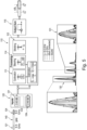
Figure 1 illustrates anRF device 100, according to an exemplary embodiment of the disclosure. TheRF device 100 comprises a control device 110 (e.g. one or more processors) coupled (directly or remotely, e.g. wired or wireless) with a plurality of channels 120 (channel inputs). TheRF device 100 is in this example an UWB radar device configured according to the IEEE standard. A transmitter is not shown in this example but of the receiver is illustrated by theinput channels 120. The transmitter transmits one or more RF radar signals which is/are then reflected by a target. The reflected radar signals are then received by the channels of thereceiver 120. Alternatively, RF signals from another entity can be received. - The
receiver 120 comprises in this example two (sub-) channels: afirst channel 121 with a first frequency band and asecond channel 122 with a second frequency band. In this example, the base band channels 5 and 9 of the IEEE standard are applied. It should be noticed that thesechannels first channel 121 is configured to receive a first signal, while thesecond channel 122 is configured to receive a second signal. The signals can be the same for the channels or different for eachchannel first channel 121 measures a first channel response as a first channel impulse response and thesecond channel 122 measures a second channel response as a second channel impulse response. These channel impulse responses are then sent to thecontrol device 110. - The
control device 110 is configured to obtain said channel impulse responses (CIR) and to combine the first CIR and the second CIR bychannel stitching 112 to obtain a combined channel (impulse)response 115, i.e. a combined spectrum, as the output. It can be seen inFigure 1 that thechannel stitching 112 is done based on the number of bands (n) and the center frequency (fst): n*fst, wherein
- In order not to lose information, the sampling rate can be scaled with the number of bands, when calculating the output sum, e.g. resampling Ts -> Ts / NB.
- Before performing the
actual channel stitching 112, there is applied acalibration 111 to align the first CIR and the second CIR with each other. To perform such an alignment, the parameter (steering vector) ϕ0 needs to be estimated. In the present case, acalibration base 130 is determined, which is in this example the most dominant peak (strongest multipath-component, at position n0, n0 -> max) of the channel impulse responses which is chosen to estimate ϕ0. Based on thecalibration base 130, a steering towards saidcalibration base 130 is performed for the first CIR and the second CIR in order to obtain/correct a phase offset and a coherence between the CIRs. - In other words, a three-step processing can be applied: calibration (determine calibration base), steering (towards the calibration base, steering centers the phase of sub-bands to gain inter-band coherence) and stitching (combination). The shown formula (r_st) is an illustrative summary of all the three steps in one turn:
- i) r_BB are the CIRs from single channels (in baseband),
- ii) these get first the calibration phase shift phi_0 (obtained here from the strongest peak), and
- iii) then the steering (n_0 * ΔB) (here position of strongest peak and distance of center frequencies), and
- iv) finally the stitch (n * f_st) (linear phase to shift the band).
-
Figure 2 compares different channel impulse responses, including the combination of two adjacent channels, according to exemplary embodiments of the disclosure. On the left side, there is shown a CIR diagram with the amplitude indicated at the y-axis and the path length in meter indicated at the x-axis. Three peaks are visible in the CIR diagram, which can be associated e.g. with a target and/or a surface. The following CIRs are shown: - i) a CIR of a first (sub-)
channel 121 with a center frequency at 6.5 GHz (bandwidth 500 MHz), - ii) a CIR of an adjacent
second channel 122 with a center frequency at 7 GHz (bandwidth 500 MHz), - iii) a combined CIR, whereby the first CIR and the second CIR have been calibrated and stitched together,
- iv) a single channel with double bandwidth (without stitching) to illustrate that the stitching can appropriately double the bandwidth.
- The term "circular AWGN" refers to the noise model which is circular additive white gaussian noise to simulate a more realistic channel.
- On the right side, there is shown a detailed view of the dominant peak 130 (strongest multipath component).
- On top, it is schematically shown that the bandwidths of the two
adjacent channels 121, 122 (each being 500 MHz) are combined by stitching to a combined bandwidth of 1 GHz, thereby effectively gaining the double bandwidth. - It can be seen that the combined (stitched) channel CIR has a significantly higher accuracy/resolution as the single channel CIRs. The
dominant peak 130 can be used in this example as the calibration base to calibrate/align the first CIR and the second CIR. -
Figure 3 compares different channel impulse responses, including the combination of four adjacent channels, according to exemplary embodiments of the disclosure. On the left side, there is shown a CIR diagram with the amplitude indicated at the y-axis and the path length in meter indicated at the x-axis. Three peaks are visible in the CIR diagram, which can be associated e.g. with a target and/or a surface. The following CIRs are shown: - i) a CIR of a first (sub-)
channel 121 with a center frequency at 6.5 GHz (bandwidth 500 MHz), - ii) a CIR of an adjacent
second channel 122 with a center frequency at 7 GHz (bandwidth 500 MHz), - iii) a combined CIR, whereby the first CIR, the second CIR, a third CIR from a
third channel 123 with a center frequency at 7.5 GHz, and a fourth CIR from a fourth channel with a center frequency at 8 GHz have been calibrated and stitched together, - iv) single channel with quadruple bandwidth (without stitching) to illustrate that the stitching can appropriately quadruple the bandwidth.
- On the right side, there is shown a detailed view of the dominant peak 130 (strongest multipath component).
- On top, it is schematically shown that the bandwidths of the four
adjacent channels - It can be seen that the combined (stitched) channel CIR has a significantly higher accuracy/resolution as the single channel CIRs. The
dominant peak 130 can be used in this example as the calibration base to calibrate/align the first CIR, the second CIR, the third CIR, and the fourth CIR. -
Figure 4 compares different channel impulse responses, including the combination of four non-adjacent channels, according to exemplary embodiments of the disclosure. On the left side, there is shown a CIR diagram with the amplitude indicated at the y-axis and the path length in meters indicated at the x-axis. Three peaks are visible in the CIR diagram, which can be associated e.g. with a target and/or a surface. The following CIRs are shown: - i) a CIR of a first (sub-)
channel 121 with a center frequency at 6.5 GHz (bandwidth 500 MHz), - ii) a CIR of an adjacent
second channel 122 with a center frequency at 7.25 GHz (bandwidth 1 GHz), - iii) a combined CIR, whereby the first CIR, the second CIR, and a fourth CIR from a fourth channel with a center frequency at 8 GHz have been calibrated and stitched together, whereby a
frequency gap 140 is present between the second frequency band and the fourth bandwidth, - iv) single channel with quadruple bandwidth (without stitching) to illustrate that the stitching can appropriately quadruple the bandwidth.
- On the right side, there is shown a detailed view of the dominant peak 130 (strongest multipath component).
- On top, it is schematically shown that the bandwidths of the two
adjacent channels 121, 122 (first and second channel) and the non-adjacentfourth channel 124 are combined by stitching to a combined bandwidth of 2 GHz, thereby effectively gaining the quadruple bandwidth. - It can be seen that the combined (stitched) channel CIR has a significantly higher accuracy/resolution as the single channel CIRs. The
dominant peak 130 can be used in this example as the calibration base to calibrate/align the first CIR, the second CIR, and the fourth CIR. -
Figure 5 illustrates the RF device 100 (seeFigure 1 ) in a configuration, wherein atarget peak 131 is selected as a calibration base instead of thedominant peak 130, according to an exemplary embodiment of the disclosure. In this example, where there is agap 140 between the appliedfirst channel 121 bandwidth andfourth channel 124 bandwidth. Having a closer look on the dominant peak 130 (left side), it can be seen a distortion, while the target peak 131 (right side) shows no distortion. Accordingly, the target peak 131 (region) can be determined with high accuracy/resolution, but not the dominant peak 130 (region). The described bandwidth doubling is hence achieved for a specific target tap (at thetarget peak 131 region). -
Figure 6 illustrates the RF device 100 (seeFigure 1 ) in a configuration, wherein a self-interference peak 132 is selected as acalibration base 130, according to an exemplary embodiment of the disclosure. For this specific example, theRF device 100 is configured as a monostatic radar, wherein the transmitter and the receiver are co-located, i.e. arranged in the same entity. An interference between transmitter and receiver results in the (device-specific) self-interference peak 132 in each CIR. In this manner, the self-interference peak 132 can be used as the calibration base, and the calibration/steering can be done independent of the target. Thereby, for example the resolution of two or more (spatially close) targets can be improved. -
Figures 7A and 7B schematically illustrates an algorithm of performingsteering 114 andstitching 112 to find the (true earliest) first path in case where the strongest peak (acquisition path) is not the first path, according to exemplary embodiments of the disclosure. Hereby, the acquisition path is the strongest component in the CIR, while the first path (first peak) is the physical earliest component, which may not necessarily be the strongest comment, e.g. due to line-of-sight blockage and/or diffuse multipath propagation. The basic idea of this algorithm comes from the effect seen inFigure 5 : steering towards the strongest peak (acquisition path) can make the target peak (first path) distorted and/or weaker. Following the algorithm shown, it is iterated over the CIR taps before the acquisition path and each time steer is done to the corresponding distance. When the first path is reached, then the distortion is resolved and the threshold should be surpassed. - This algorithm can be well suited for the case of spectral gaps, but it can also be used when there are no gaps because the initial steering to the acquisition peak can be not fully accurate and doing the iterations as described above might lead to the correct steering distance (d_0) and thus helps finding the true first path.
-
Figure 7A : there is shown a CIR estimate, a detection threshold, and a noise estimate. Within a search-back window, it is shown the acquisition path and the first path. -
Figure 7B : shows schematically the above described first path search algorithm with respect to the CIR estimate forFigure 7A . The steering coefficients are calibrated on a strong tap (acquisition path). Iteratively, steering coefficients are then adjusted to the first path search position, and the algorithm is stopped, when the first path is found. - For
Figure 8 , a conventional example has already been described above. However, according to the present disclosure, a bandwidth of B = 1 GHz can be applied, and the resolution and accuracy can be clearly improved.
Claims (15)
- A device (100), being a radio frequency, RF, device (100), comprising:a first channel (121) with a first frequency band, configured to receive a first signal;a second channel (122) with a second frequency band, configured to receive a second signal, wherein the first frequency band and the second frequency band are different; anda control device (110), configured to:obtain a first channel response associated with the received first signal at the first channel (121);obtain a second channel response associated with the received second signal at the second channel (122);calibrate (111) the first channel response and the second channel response by steering (114) to a calibration base (130); andcombine the first channel response and second channel response by channel stitching (112) to obtain a combined channel response (115).
- The device (100) according to claim 1,
wherein the first frequency band and the second frequency band are adjacent to each other or non-adjacent to each other. - The device (100) according to claim 2,
wherein the first frequency band and the second frequency band have a frequency gap (140) in between. - The device (100) according to one of the preceding claims,
wherein the device (100) is an ultra-wide band, UWB, device. - The device (100) according to one of the preceding claims,
wherein the calibration base (130) is associated with at least one of:a dominant peak (130);the most dominant peak;a dominant multipath component;a target peak (131);a self-interference peak (132). - The device (100) according to claim 5,wherein calibration (111) is performed to correct at least one ofa constant phase offset,a steering phase offset,between the first channel response (121) and the second channel response (122).
- The device (100) according to claim 5 or 6,
wherein steering (114) is performed to center a first phase of the first channel response and a second phase of the second channel response to obtain a coherence of the first channel response and the second channel response. - The device (100) according to one of the preceding claims, wherein the control device (110) is further configured to:
process at least one of the first channel response, the second channel response, the combined channel response (115). - The device (100) according to one of the preceding claims,
comprising three or more channels (121-124), and at least one of:wherein two or more channels are adjacent,wherein two or more channels are non-adjacent. - The device (100) according to one of the preceding claims,
wherein the control device is further configured to, in case that in at least one of the first channel response,the second channel response,the first peak (131) is not the strongest peak (131):identify the strongest peak (130),define a calibration base window based on the identified strongest peak (130), anditeratively steer over the calibration base window to identify the first peak (131). - The device (100) according to one of the preceding claims, comprising at least one of the following features:further comprising a receiver to receive the signal, wherein the receiver comprises the first channel (121) and the second channel (122);wherein the first channel response is a first channel impulse response, CIR;wherein the second channel response is a second CIR;wherein the first channel response is associated with a first spectrum;wherein the second channel response is associated with second spectrum;wherein the combined channel response is associated with a combined spectrum;wherein the channels (121, 122) are configured in accordance with an IEEE standard.
- A method of operating a radio frequency, RF, device (100), the method comprising:obtaining a first channel response associated with a received first signal at a first channel (121) with a first frequency band;obtaining a second channel response associated with the received second signal at a second channel (122) with a second frequency band,wherein the first frequency band and the second frequency band are different;calibrating (111) the first channel response and the second channel response by steering (114) to a calibration base (130); andcombining the first channel response with the second channel response for obtaining a combined channel response (115), wherein combining comprises channel stitching (112).
- The method according to claim 12,wherein the calibration base (130) is associated with a target, andwherein at least one property of the target is known.
- The method of claim 12 or 13, further comprising:
applying the combined channel response (115) to determine a spatial characteristic. - Using steering (114) to a calibration base (130) to calibrate channels (121, 122) with non-adjacent frequency bands in channel stitching (112).
Priority Applications (3)
| Application Number | Priority Date | Filing Date | Title |
|---|---|---|---|
| EP23203273.0A EP4538736A1 (en) | 2023-10-12 | 2023-10-12 | Device with steering and channel stitching for an extended bandwidth |
| CN202411291568.3A CN119834833A (en) | 2023-10-12 | 2024-09-14 | Apparatus with steering and channel splicing to extend bandwidth |
| US18/906,053 US20250125995A1 (en) | 2023-10-12 | 2024-10-03 | Device with steering and channel stitching for an extended bandwidth |
Applications Claiming Priority (1)
| Application Number | Priority Date | Filing Date | Title |
|---|---|---|---|
| EP23203273.0A EP4538736A1 (en) | 2023-10-12 | 2023-10-12 | Device with steering and channel stitching for an extended bandwidth |
Publications (1)
| Publication Number | Publication Date |
|---|---|
| EP4538736A1 true EP4538736A1 (en) | 2025-04-16 |
Family
ID=88412430
Family Applications (1)
| Application Number | Title | Priority Date | Filing Date |
|---|---|---|---|
| EP23203273.0A Pending EP4538736A1 (en) | 2023-10-12 | 2023-10-12 | Device with steering and channel stitching for an extended bandwidth |
Country Status (3)
| Country | Link |
|---|---|
| US (1) | US20250125995A1 (en) |
| EP (1) | EP4538736A1 (en) |
| CN (1) | CN119834833A (en) |
Citations (2)
| Publication number | Priority date | Publication date | Assignee | Title |
|---|---|---|---|---|
| US8169358B1 (en) * | 2007-06-25 | 2012-05-01 | Bbn Technologies | Coherent multi-band radar and communications transceiver |
| CN103630878A (en) * | 2013-01-31 | 2014-03-12 | 中国科学院电子学研究所 | Frequency band fusion method and device based on adaptive iteration scheme |
Family Cites Families (28)
| Publication number | Priority date | Publication date | Assignee | Title |
|---|---|---|---|---|
| US6128276A (en) * | 1997-02-24 | 2000-10-03 | Radix Wireless, Inc. | Stacked-carrier discrete multiple tone communication technology and combinations with code nulling, interference cancellation, retrodirective communication and adaptive antenna arrays |
| US7200162B2 (en) * | 2001-08-31 | 2007-04-03 | Qualcomm, Incorporated | Interpolation of channel search results |
| US6748009B2 (en) * | 2002-02-12 | 2004-06-08 | Interdigital Technology Corporation | Receiver for wireless telecommunication stations and method |
| US7190750B2 (en) * | 2002-02-28 | 2007-03-13 | Qualcomm Incorporated | Rake receiver for tracking closely spaced multipath |
| US7277474B2 (en) * | 2002-11-05 | 2007-10-02 | Analog Devices, Inc. | Finger allocation for a path searcher in a multipath receiver |
| WO2005033728A2 (en) * | 2003-05-22 | 2005-04-14 | General Atomics | Ultra-wideband radar system using sub-band coded pulses |
| US7983323B2 (en) * | 2004-10-06 | 2011-07-19 | Broadcom Corporation | Method and system for managing, controlling, and combining signals in a frequency selective multipath fading channel |
| US7889781B2 (en) * | 2006-09-21 | 2011-02-15 | Broadcom Corporation | Maximum energy delay locked loop for cluster path processing in a wireless device |
| US8610521B2 (en) * | 2011-10-27 | 2013-12-17 | Apple Inc. | Noise-suppressing orbital relay assembly |
| US8805297B2 (en) * | 2012-10-16 | 2014-08-12 | Raytheon Company | Band stitching electronic circuits and techniques |
| US9154337B2 (en) * | 2013-03-15 | 2015-10-06 | Acorn Technologies, Inc. | Non-linear time domain channel estimation in OFDM systems |
| US8897353B2 (en) * | 2013-03-15 | 2014-11-25 | Acorn Technologies, Inc. | Block time domain channel estimation in OFDM system |
| US9148752B2 (en) * | 2013-04-02 | 2015-09-29 | Cisco Technology, Inc. | Scalable multi-channel ranging |
| US20160227516A1 (en) * | 2015-02-03 | 2016-08-04 | Qualcomm Incorporated | Sparsity and continuity-based channel stitching techniques for adjacent transmissions |
| EP3255851B1 (en) * | 2016-06-08 | 2019-08-07 | Nxp B.V. | Processing module for a communication device and method therefor |
| US10164670B2 (en) * | 2016-09-03 | 2018-12-25 | National Instruments Corporation | Time sequenced spectral stitching |
| US10243710B2 (en) * | 2016-09-06 | 2019-03-26 | Apple Inc. | Spectral aggregation to generate a wideband channel estimation |
| EP3370082B1 (en) * | 2017-03-02 | 2020-12-09 | Nxp B.V. | Processing module and associated method |
| US10320431B2 (en) * | 2017-07-27 | 2019-06-11 | Huawei Technologies Co., Ltd. | Method and apparatus for interference cancellation in full-duplex multi-cell networks |
| US10327221B1 (en) * | 2018-05-25 | 2019-06-18 | Apple Inc. | Super-resolution technique for time-of-arrival estimation |
| US10623121B1 (en) * | 2018-07-31 | 2020-04-14 | Nxp Usa, Inc. | Systems and methods for time delay estimation |
| US11381329B2 (en) * | 2020-05-12 | 2022-07-05 | Nxp B.V. | Detecting a moving object based on a phase of channel impulse responses |
| US11729037B2 (en) * | 2020-11-02 | 2023-08-15 | Apple Inc. | Sequences for ultra-wideband ranging |
| EP4155753B1 (en) * | 2021-09-22 | 2025-02-12 | Nxp B.V. | An ultra-wideband receiver module and synchronization thereof |
| US12476847B2 (en) * | 2022-03-08 | 2025-11-18 | Qualcomm Incorporated | Radio frequency sensing with channel impulse response |
| US20240073072A1 (en) * | 2022-08-26 | 2024-02-29 | Qualcomm Incorporated | Channel stitching for cellular based radio frequency sensing |
| US12248059B2 (en) * | 2022-09-12 | 2025-03-11 | Qualcomm Incorporated | Wideband-assisted ultra-wideband (UWB) sensing |
| US12519678B2 (en) * | 2023-05-14 | 2026-01-06 | Qualcomm Incorporated | Radio frequency sensing control for an ultra-wideband system |
-
2023
- 2023-10-12 EP EP23203273.0A patent/EP4538736A1/en active Pending
-
2024
- 2024-09-14 CN CN202411291568.3A patent/CN119834833A/en active Pending
- 2024-10-03 US US18/906,053 patent/US20250125995A1/en active Pending
Patent Citations (2)
| Publication number | Priority date | Publication date | Assignee | Title |
|---|---|---|---|---|
| US8169358B1 (en) * | 2007-06-25 | 2012-05-01 | Bbn Technologies | Coherent multi-band radar and communications transceiver |
| CN103630878A (en) * | 2013-01-31 | 2014-03-12 | 中国科学院电子学研究所 | Frequency band fusion method and device based on adaptive iteration scheme |
Also Published As
| Publication number | Publication date |
|---|---|
| US20250125995A1 (en) | 2025-04-17 |
| CN119834833A (en) | 2025-04-15 |
Similar Documents
| Publication | Publication Date | Title |
|---|---|---|
| CN112763985B (en) | Pulse Doppler radar sounding integrated waveform design method | |
| CN110520750B (en) | Method and system for wireless detection of objects using MIMO radar | |
| US11105912B2 (en) | Coherent Wi-Fi radar using wireless access point | |
| US10024958B2 (en) | Radar apparatus | |
| US8116350B1 (en) | Ultrawideband asynchronous tracking system and method | |
| KR100939276B1 (en) | UWB distance measuring system and its driving method | |
| US7990310B2 (en) | Ultra-wideband ranging method and system using narrowband interference supression waveform | |
| US20120133558A1 (en) | High-Precision Radio Frequency Ranging System | |
| JP2008008887A (en) | Signal arrival angle determination method, signal arrival angle determination apparatus, and system for determining signal arrival angle | |
| US12222436B2 (en) | Radar method and radar system | |
| Overdevest et al. | Uncorrelated interference in 79 GHz FMCW and PMCW automotive radar | |
| CN110471034B (en) | Ultra-wideband radar waveform design method | |
| EP4009075B1 (en) | Radio frequency distance determination | |
| Moschevikin et al. | Investigations on passive channel impulse response of ultra wide band signals for monitoring and safety applications | |
| US20260098935A1 (en) | Radar device with enlarged bandwidth | |
| US11841451B2 (en) | Communication device and method | |
| US20260086192A1 (en) | Radar device with self-interference based compensation | |
| US20250125995A1 (en) | Device with steering and channel stitching for an extended bandwidth | |
| Yajnanarayana et al. | Bi-static sensing in OFDM wireless systems for indoor scenarios | |
| Sheikh | Impact of 2.4 GHz Interference on Bluetooth® 6.0 Channel Sounding Ranging Measurements | |
| Sark et al. | An approach for implementation of ranging and positioning methods on a software defined radio | |
| US7298312B2 (en) | Detecting small, time domain impulsive communications signals | |
| Yin et al. | Embedded ranging system in ISM band | |
| Lim et al. | Radar signal processing | |
| EP4641252A1 (en) | Method of performing radar operations, radar device and radar system |
Legal Events
| Date | Code | Title | Description |
|---|---|---|---|
| PUAI | Public reference made under article 153(3) epc to a published international application that has entered the european phase |
Free format text: ORIGINAL CODE: 0009012 |
|
| STAA | Information on the status of an ep patent application or granted ep patent |
Free format text: STATUS: THE APPLICATION HAS BEEN PUBLISHED |
|
| AK | Designated contracting states |
Kind code of ref document: A1 Designated state(s): AL AT BE BG CH CY CZ DE DK EE ES FI FR GB GR HR HU IE IS IT LI LT LU LV MC ME MK MT NL NO PL PT RO RS SE SI SK SM TR |
|
| STAA | Information on the status of an ep patent application or granted ep patent |
Free format text: STATUS: REQUEST FOR EXAMINATION WAS MADE |
|
| 17P | Request for examination filed |
Effective date: 20251016 |