EP4538606A2 - Air handling unit - Google Patents
Air handling unit Download PDFInfo
- Publication number
- EP4538606A2 EP4538606A2 EP25161552.2A EP25161552A EP4538606A2 EP 4538606 A2 EP4538606 A2 EP 4538606A2 EP 25161552 A EP25161552 A EP 25161552A EP 4538606 A2 EP4538606 A2 EP 4538606A2
- Authority
- EP
- European Patent Office
- Prior art keywords
- ahu
- fan
- fan assembly
- housing
- heat exchanger
- Prior art date
- Legal status (The legal status is an assumption and is not a legal conclusion. Google has not performed a legal analysis and makes no representation as to the accuracy of the status listed.)
- Pending
Links
Images








Classifications
-
- F—MECHANICAL ENGINEERING; LIGHTING; HEATING; WEAPONS; BLASTING
- F24—HEATING; RANGES; VENTILATING
- F24H—FLUID HEATERS, e.g. WATER OR AIR HEATERS, HAVING HEAT-GENERATING MEANS, e.g. HEAT PUMPS, IN GENERAL
- F24H3/00—Air heaters
- F24H3/02—Air heaters with forced circulation
- F24H3/06—Air heaters with forced circulation the air being kept separate from the heating medium, e.g. using forced circulation of air over radiators
- F24H3/08—Air heaters with forced circulation the air being kept separate from the heating medium, e.g. using forced circulation of air over radiators by tubes
-
- F—MECHANICAL ENGINEERING; LIGHTING; HEATING; WEAPONS; BLASTING
- F24—HEATING; RANGES; VENTILATING
- F24H—FLUID HEATERS, e.g. WATER OR AIR HEATERS, HAVING HEAT-GENERATING MEANS, e.g. HEAT PUMPS, IN GENERAL
- F24H3/00—Air heaters
- F24H3/02—Air heaters with forced circulation
- F24H3/06—Air heaters with forced circulation the air being kept separate from the heating medium, e.g. using forced circulation of air over radiators
- F24H3/08—Air heaters with forced circulation the air being kept separate from the heating medium, e.g. using forced circulation of air over radiators by tubes
- F24H3/087—Air heaters with forced circulation the air being kept separate from the heating medium, e.g. using forced circulation of air over radiators by tubes using fluid fuel
-
- F—MECHANICAL ENGINEERING; LIGHTING; HEATING; WEAPONS; BLASTING
- F24—HEATING; RANGES; VENTILATING
- F24F—AIR-CONDITIONING; AIR-HUMIDIFICATION; VENTILATION; USE OF AIR CURRENTS FOR SCREENING
- F24F5/00—Air-conditioning systems or apparatus not covered by F24F1/00 or F24F3/00, e.g. using solar heat or combined with household units such as an oven or water heater
- F24F5/0007—Air-conditioning systems or apparatus not covered by F24F1/00 or F24F3/00, e.g. using solar heat or combined with household units such as an oven or water heater cooling apparatus specially adapted for use in air-conditioning
-
- F—MECHANICAL ENGINEERING; LIGHTING; HEATING; WEAPONS; BLASTING
- F23—COMBUSTION APPARATUS; COMBUSTION PROCESSES
- F23D—BURNERS
- F23D99/00—Subject matter not provided for in other groups of this subclass
- F23D99/002—Burners specially adapted for specific applications
-
- F—MECHANICAL ENGINEERING; LIGHTING; HEATING; WEAPONS; BLASTING
- F24—HEATING; RANGES; VENTILATING
- F24F—AIR-CONDITIONING; AIR-HUMIDIFICATION; VENTILATION; USE OF AIR CURRENTS FOR SCREENING
- F24F13/00—Details common to, or for air-conditioning, air-humidification, ventilation or use of air currents for screening
-
- F—MECHANICAL ENGINEERING; LIGHTING; HEATING; WEAPONS; BLASTING
- F24—HEATING; RANGES; VENTILATING
- F24F—AIR-CONDITIONING; AIR-HUMIDIFICATION; VENTILATION; USE OF AIR CURRENTS FOR SCREENING
- F24F13/00—Details common to, or for air-conditioning, air-humidification, ventilation or use of air currents for screening
- F24F13/28—Arrangement or mounting of filters
-
- F—MECHANICAL ENGINEERING; LIGHTING; HEATING; WEAPONS; BLASTING
- F24—HEATING; RANGES; VENTILATING
- F24F—AIR-CONDITIONING; AIR-HUMIDIFICATION; VENTILATION; USE OF AIR CURRENTS FOR SCREENING
- F24F13/00—Details common to, or for air-conditioning, air-humidification, ventilation or use of air currents for screening
- F24F13/30—Arrangement or mounting of heat-exchangers
-
- F—MECHANICAL ENGINEERING; LIGHTING; HEATING; WEAPONS; BLASTING
- F24—HEATING; RANGES; VENTILATING
- F24F—AIR-CONDITIONING; AIR-HUMIDIFICATION; VENTILATION; USE OF AIR CURRENTS FOR SCREENING
- F24F3/00—Air-conditioning systems in which conditioned primary air is supplied from one or more central stations to distributing units in the rooms or spaces where it may receive secondary treatment; Apparatus specially designed for such systems
- F24F3/001—Air-conditioning systems in which conditioned primary air is supplied from one or more central stations to distributing units in the rooms or spaces where it may receive secondary treatment; Apparatus specially designed for such systems in which the air treatment in the central station takes place by means of a heat-pump or by means of a reversible cycle
-
- F—MECHANICAL ENGINEERING; LIGHTING; HEATING; WEAPONS; BLASTING
- F24—HEATING; RANGES; VENTILATING
- F24F—AIR-CONDITIONING; AIR-HUMIDIFICATION; VENTILATION; USE OF AIR CURRENTS FOR SCREENING
- F24F3/00—Air-conditioning systems in which conditioned primary air is supplied from one or more central stations to distributing units in the rooms or spaces where it may receive secondary treatment; Apparatus specially designed for such systems
- F24F3/12—Air-conditioning systems in which conditioned primary air is supplied from one or more central stations to distributing units in the rooms or spaces where it may receive secondary treatment; Apparatus specially designed for such systems characterised by the treatment of the air otherwise than by heating and cooling
- F24F3/14—Air-conditioning systems in which conditioned primary air is supplied from one or more central stations to distributing units in the rooms or spaces where it may receive secondary treatment; Apparatus specially designed for such systems characterised by the treatment of the air otherwise than by heating and cooling by humidification; by dehumidification
-
- F—MECHANICAL ENGINEERING; LIGHTING; HEATING; WEAPONS; BLASTING
- F24—HEATING; RANGES; VENTILATING
- F24F—AIR-CONDITIONING; AIR-HUMIDIFICATION; VENTILATION; USE OF AIR CURRENTS FOR SCREENING
- F24F8/00—Treatment, e.g. purification, of air supplied to human living or working spaces otherwise than by heating, cooling, humidifying or drying
- F24F8/10—Treatment, e.g. purification, of air supplied to human living or working spaces otherwise than by heating, cooling, humidifying or drying by separation, e.g. by filtering
-
- F—MECHANICAL ENGINEERING; LIGHTING; HEATING; WEAPONS; BLASTING
- F24—HEATING; RANGES; VENTILATING
- F24H—FLUID HEATERS, e.g. WATER OR AIR HEATERS, HAVING HEAT-GENERATING MEANS, e.g. HEAT PUMPS, IN GENERAL
- F24H9/00—Details
- F24H9/02—Casings; Cover lids; Ornamental panels
-
- F—MECHANICAL ENGINEERING; LIGHTING; HEATING; WEAPONS; BLASTING
- F24—HEATING; RANGES; VENTILATING
- F24H—FLUID HEATERS, e.g. WATER OR AIR HEATERS, HAVING HEAT-GENERATING MEANS, e.g. HEAT PUMPS, IN GENERAL
- F24H9/00—Details
- F24H9/06—Arrangement of mountings or supports
-
- F—MECHANICAL ENGINEERING; LIGHTING; HEATING; WEAPONS; BLASTING
- F24—HEATING; RANGES; VENTILATING
- F24H—FLUID HEATERS, e.g. WATER OR AIR HEATERS, HAVING HEAT-GENERATING MEANS, e.g. HEAT PUMPS, IN GENERAL
- F24H9/00—Details
- F24H9/14—Arrangements for connecting different sections, e.g. in water heaters
- F24H9/148—Arrangements of boiler components on a frame or within a casing to build the fluid heater, e.g. boiler
-
- F—MECHANICAL ENGINEERING; LIGHTING; HEATING; WEAPONS; BLASTING
- F24—HEATING; RANGES; VENTILATING
- F24H—FLUID HEATERS, e.g. WATER OR AIR HEATERS, HAVING HEAT-GENERATING MEANS, e.g. HEAT PUMPS, IN GENERAL
- F24H9/00—Details
- F24H9/18—Arrangement or mounting of grates or heating means
- F24H9/1854—Arrangement or mounting of grates or heating means for air heaters
-
- F—MECHANICAL ENGINEERING; LIGHTING; HEATING; WEAPONS; BLASTING
- F24—HEATING; RANGES; VENTILATING
- F24H—FLUID HEATERS, e.g. WATER OR AIR HEATERS, HAVING HEAT-GENERATING MEANS, e.g. HEAT PUMPS, IN GENERAL
- F24H9/00—Details
- F24H9/18—Arrangement or mounting of grates or heating means
- F24H9/1854—Arrangement or mounting of grates or heating means for air heaters
- F24H9/1877—Arrangement or mounting of combustion heating means, e.g. grates or burners
- F24H9/1881—Arrangement or mounting of combustion heating means, e.g. grates or burners using fluid fuel
-
- F—MECHANICAL ENGINEERING; LIGHTING; HEATING; WEAPONS; BLASTING
- F23—COMBUSTION APPARATUS; COMBUSTION PROCESSES
- F23D—BURNERS
- F23D2205/00—Assemblies of two or more burners, irrespective of fuel type
-
- F—MECHANICAL ENGINEERING; LIGHTING; HEATING; WEAPONS; BLASTING
- F24—HEATING; RANGES; VENTILATING
- F24F—AIR-CONDITIONING; AIR-HUMIDIFICATION; VENTILATION; USE OF AIR CURRENTS FOR SCREENING
- F24F2221/00—Details or features not otherwise provided for
- F24F2221/34—Heater, e.g. gas burner, electric air heater
-
- F—MECHANICAL ENGINEERING; LIGHTING; HEATING; WEAPONS; BLASTING
- F24—HEATING; RANGES; VENTILATING
- F24F—AIR-CONDITIONING; AIR-HUMIDIFICATION; VENTILATION; USE OF AIR CURRENTS FOR SCREENING
- F24F2221/00—Details or features not otherwise provided for
- F24F2221/36—Modules, e.g. for an easy mounting or transport
-
- F—MECHANICAL ENGINEERING; LIGHTING; HEATING; WEAPONS; BLASTING
- F24—HEATING; RANGES; VENTILATING
- F24F—AIR-CONDITIONING; AIR-HUMIDIFICATION; VENTILATION; USE OF AIR CURRENTS FOR SCREENING
- F24F2221/00—Details or features not otherwise provided for
- F24F2221/54—Heating and cooling, simultaneously or alternatively
Definitions
- HVAC heating, ventilation, air conditioning, and refrigeration
- HVACR heating, ventilation, air conditioning, and refrigeration
- HVACR systems are generally used to heat, cool, and/or ventilate an enclosed space (e.g., an interior space of a commercial building or a residential building, an interior space of a refrigerated transport unit, or the like).
- An AHU is part of a HVACR system that is used to regulate and circulate air.
- a ductwork ventilation system can be connected to the AHU and directs conditioned air from the AHU to the enclosed space and air from the conditioned space to the AHU.
- the AHU can include a housing, fan(s), and heat exchanger(s).
- the heat exchanger be a combustion heater that directs combustion gases through heat exchanger tubes to heat air flowing past the heat exchanger tubes as it flows through the AHU.
- the AHU can also include one or more components of a refrigerant circuit of the HVACR system used to cool the air (e.g., the condenser, the evaporator, and the like).
- HVAC heating, ventilation, air conditioning, and refrigeration
- the HVACR system can utilize an air handling unit (“AHU”) to regulate and circulate air.
- the air handling unit receives air (e.g., air from the conditioned space, ambient air, and the like) and discharges conditioned air (e.g., heated, cooled, dehumidified, filtered, and the like) that is supplied to the conditioned space.
- air e.g., air from the conditioned space, ambient air, and the like
- conditioned air e.g., heated, cooled, dehumidified, filtered, and the like
- the AHU includes a housing containing a combustion section and a combustion heater that disposed within the housing.
- the housing includes a first side with an opening for the combustion section.
- the combustion section has a first side wall with a first channel and a second side wall with a second channel.
- the combustion heater includes an end plate, heat exchanger tubes, and a tube support.
- the heat exchanger tubes extend from the end plate and into the combustion section.
- the tube support is slidably disposed in the first channel and the second channel and supports the heat exchanger tubes within the combustion section.
- the tube support is configured to slidably move through the first channel and the second channel in a first direction that moves the combustion heater through the opening in the housing.
- the tube support is configured to slidably move in the first direction through and from the first channel and the second channel such that the combustion heater is entirely moved through the opening in the housing.
- the first channel and the second channel each have an open end.
- the tube support has a retaining member slidably disposed in the first channel and the second channel. The moving the retaining member in the first direction through the open ends of the first channel and the second channel is configured to separate the combustion heater from the housing.
- the first channel and the second channel are configured to not limit the movement of the tube support in the first direction.
- the tube support includes a retaining member, the retaining member having a first end disposed in the first channel and a second end disposed in the second channel.
- the tube support includes a vertical support and a plurality of contact arms.
- the vertical support extends from the retaining member and each of the contact arms extends from the vertical support.
- Each of the heat exchanger tubes rests on a respective one of the plurality of contact arms.
- each of the contact arms extends between a vertically adjacent pair of the heat exchanger tubes.
- the first channel and the second channel are configured to restrict vertical movement of the tube support while allowing the tube support to move in the first direction.
- first channel and the second channel are formed by a pair of brackets provided on opposite walls of the combustion section.
- the AHU includes one or more support clips for the heat exchanger tubes.
- Each of the support clips is fitted around a vertically adjacent pair of the heat exchanger tubes.
- FIG 1 is a schematic diagram of an embodiment of a heating, ventilation, air conditioning, and refrigeration (“HVACR”) system 1.
- HVACR system 1 is configured to condition (e.g., heat, cool, dehumidify, and the like) a conditioned space by supplying conditioned air to the conditioned space 3.
- the HVACR system can include a ductwork ventilation system 5 and an air handling unit (“AHU") 10.
- AHU 10 is connected to the ductwork ventilation system 5 that is configured to distribute the conditioned air discharged from the AHU 10 to the conditioned space 3.
- the ductwork ventilation system 5 can also return air from the conditioned space 3 back to the AHU 10.
- the air to be conditioned flows through the AHU 10 from an inlet 12A to the outlet 12B of the AHU 10.
- the air is conditioned as it flows from the inlet 12A to the outlet 12B of the AHU such that conditioned air is discharged from the outlet 12B.
- the AHU 10 is configured to be capable of cooling and heating the air as it flows through the AHU 10. In a heating mode, the AHU 10 heats the air as it flows through the AHU 10. In a cooling mode, the AHU 10 cools the air as it flows through the AHU 10.
- the HVACR system 1 can include a refrigerant circuit 20 to provide cooling.
- the refrigerant circuit 20 can include a compressor 22, a condenser 24, an expander 26, and an evaporator 28.
- the heat transfer circuit 1 can be modified to include additional components, such as, for example, an economizer heat exchanger, one or more valve(s), sensor(s) (e.g., a flow sensor, a temperature sensor, and the like), a receiver tank, or the like.
- the components of the heat transfer circuit 1 are fluidly connected as shown by the dashed lines in Figure 1 .
- the refrigerant circuit 20 operates by known principles of refrigerant compression and expansion to provide cooling.
- Working fluid e.g., a refrigerant, a refrigerant blend, or the like
- Working fluid e.g., a refrigerant, a refrigerant blend, or the like
- the expansion causes the working fluid to cool.
- the cool working fluid then flows through the evaporator 28.
- the air flowing through the AHU 10 from the inlet 12A to the outlet 12B flows through the evaporator 28 separately from the working fluid.
- the cooler working fluid absorbs heat from the passing air and cools the air.
- the evaporator 28 cooling the air passing by/through the evaporator 28.
- the AHU 10 can contain components of the refrigerant circuit 20 other than evaporator 28.
- the AHU 10 can include a condenser section 30 that utilizes air to cool one or more components of the refrigerant circuit 20.
- the AHU 10 can be configured to operate in a heat pump mode in which the evaporator 28 instead operates as a condenser that heats the air as it flows past.
- the AHU 10 can include one or more fan(s) 32 that blow ambient air through the condenser 24 of the refrigerant circuit 20 to cool the working fluid flowing through the condenser 24.
- the compressor 20 can also be disposed in the condenser section 30.
- the side walls 140, 142 each have a channel 144A, 144B.
- the first side wall 140 includes a first channel 144A and the second side wall 142 includes a second channel 144B.
- the channels 144A, 144B disposed opposite to each other in the fan section 104.
- the first channel 144A has a longitudinal opening that faces the second side wall 142
- second channel 144A has a longitudinal opening that faces the first side wall 140.
- the two channels 144A, 144B form a slot across the fan section 104.
- the channels 144A, 144B face each other across the combustion section.
- Each of the channels 144A, 144B extends along its respective side wall 140, 142 and away from the front side 112 of the housing 112 (e.g., in the direction D 1 in Figure 2 ).
- the channels 144A, 144B can be provided using a pair of brackets 146A, 146B.
- a first bracket 146A is affixed to the first side wall 140
- a second bracket 146B is affixed to the second side wall 142.
- the first bracket 146A is affixed to the surface of the first wall 140
- the second bracket 146B is affixed to the surface of the second wall 142.
- the first and second brackets 146A, 146B can respectively form the first and second channels 144A, 144B.
- the combustion heater 130 includes a slidable tube support 150 that supports the heat exchanger tubes 136 within the interior space of the fan section 104.
- the slidable tube support 150 is configured to be slidable along in the depth direction D 1 of the fan section 102 for moving the combustion heater 130 through the opening 128 in the housing 110 (shown in Figure 3 ).
- the tube support 150 is slidable/movable relative to the housing 110. For example, this allows a technician (manually or machine assisted) to pull on the combustion heater 130 in the direction D 3 to slide the entire combustion heater 130 through the opening 128 in the housing 110.
- the opening 128 in the housing 110 is enlarged to allow removal of the combustion heater 130 by removing additional panels of the front side 112 of the housing 110.
- the slidable tube support 150 can be used to partial remove the combustion heater 130 from the housing 110 (e.g., sliding the combustion heater 130 only partway through the opening 128) or to completely remove the combustion heater 130 from the AHU 100 and the housing 110.
- the partial removal may be used by a technician to allow for easier repair of the combustion heater 130, while the full removal can be used for larger repairs and/or for replacement of the combustion heater 130.
- the slidable tube support 150 includes a retaining member 152 that is slotted into the channels 144A, 144B.
- the retaining member 152 is slidably disposed in the channels 144A, 144B.
- the retaining member 152 extends from the first channel 144A to the second channel 144B.
- the retaining member 152 extends between the first side wall 140 the second side wall 142.
- the retaining member 152 has a first end 154 and an opposite second end 156.
- the first end 154 is disposed in the first channel 144A and the second end 156 is disposed in the second channel 144B.
- Figure 5 is a partial vertical cross-sectional view of the combustion heater 130 as indicated in Figure 2 , according to an embodiment.
- Figure 5 illustrates the interaction between the slidable tube support 150 and the heat exchanger tubes 136.
- the retaining member 152 is fastened to one or more of the heat exchanger tubes 136 to prevent the retaining member 152 from moving relative to the heat exchanger tubes 136.
- the retaining member 152 can be fastened around a group of the heat exchanger tubes 136.
- the retaining member 152 can include a pair of brackets 158 that are fastened together with fasteners 160 (e.g., screws, bolts, clamps, and the like).
- the heat exchanger tubes 136 being pinched between the fastened together pair of brackets 158.
- the group of heat exchanger tubes 136 held between the pair of brackets 158.
- the slidable tube support 150 can be prevented from sliding along the heat exchange tubes 136 in a different manner.
- the slidable tube support 150 may be affixed to the heat exchange tubes 136 via welding, fasteners, or the like, or the heat exchanger tubes 136 may have exterior projections that prevent the tube support 150 from sliding along the outsides of the heat exchanger tubes 136.
- the vertical support 164 extends along a column of the heat exchanger tubes 136. As shown in Figure 5 , the vertical support 164 can extend between two adjacent columns of the heat exchanger tubes 136. In an embodiment, the vertical support 164 extend along an outside column of heat exchanger tubes 136.
- the heat exchanger tubes 136 rest on the contact arms 166.
- Each heat exchanger tube 136 can rest on a respective contact arm 166.
- the contact arms 166 help to hold the heat exchanger tubes 136.
- the bottom surface of a heat exchanger tube 136 rests on the upper surface of its respective contact arm 166.
- the contact arms 166 are prevented from vertically moving by the retaining member 152 being disposed/slotted in the channels 144A, 144B.
- the contact arms 166 vertically remain in place and provide a support surface for resting the heat exchanger tubes 136.
- Each contact arm 166 prevents/limits the downward movement of its respective heat exchanger tube 136.
- the combustion heater 130 shown in Figures 4 and 5 has a single tube support 140. However, the combustion heater 130 in an embodiment may include multiple of the tube support 140.
- the heat exchanger tubes 136 are supported within the AHU 100 by only the end plate 130 and the one or more tube support(s) 140.
- the slidable tube support 150 in Figures 4 - 6 includes a contact arm 166 for each heat exchanger tube 136.
- the sliding support 150 in an embodiment may not have a contact arm 166 for each heat exchanger tube 136.
- the support clip(s) 170 can be used to couple a heat exchanger tube 136 without a contact arm 166 to a heat exchanger tube 136 with a contact arm 166.
- the slidable tube support 150 can provide support to the heat exchanger tube 136 without a contact arm 166 via the supported heat exchanger tube 136 and said support clip(s) 170.
- Figures 7A - 7C show the combustion heater 130 in various positions when being removed from the AHU 100. Dashed lines are provided in Figures 7A and 7B to illustrate the sides of the housing 110 that form the fan section 104 of the AHU 100.
- Figure 7A shows the combustion heater 130 in a first position.
- the first position is the position in which the combustion heater 130 is installed in the AHU 100 and is ready for operation.
- the combustion heater 130 in the installed position is ready for operating to direct combustion gases through the heat exchanger tubes 136 and heats the air as it flows through the fan section 104.
- the first position can also be referred to as the installed position.
- Figure 3 also shows the combustion heater 130 in its installed position.
- Figure 7B shows the combustion heater 130 in a second position.
- the second position is a position in which the combustion heater 130 is partially slidably removed from the AHU 100.
- the combustion heater 130 in Figure 7A is slidably moved (e.g., pulled) through the opening 128 in the front side 112 of the AHU 100 to reach the second position shown in Figure 7A .
- the combustion heater 130 is slidably moved in the direction D 3 from the first position (shown in Figure 7A ) into the second position (shown in Figure 7B ).
- the second position may allow, for example, a technician to more easily access and/or work on the combustion heater 130.
- Figure 8 is a rear perspective view of an embodiment of an AHU 100.
- a panel 226 of the rear side 118 is opened and removed in Figure 9 .
- the panel 226 covers an opening 228 in the rear side 118 of housing 110 for the fan section 104 of the AHU 100.
- the opening 228 in the housing 228 can be for an upper portion of the fan section 104.
- the top side 120 of the housing 110 of the AHU 100 e.g., top side 120 in Figure 2
- Figure 8 is also removed for illustration.
- a panel 227 (shown in Figure 2 ) of the top side 120 is opened and removed in Figure 8 .
- the panel 227 covers an opening 229 in the top side 120 of the housing 110 for the fan section 104 of the AHU 100.
- the opening 229 is for the top of the fan section 104.
- the housing 110 includes a pair of rails 250A, 250B for supporting the fan assembly 230.
- the rails 250A, 250B disposed in the fan section 104.
- Each of the rails 250A, 250B has a length L that extends between the front side 112 and the rear side 118 of the housing 110.
- the rails 250A, 250B each extending away from the opening 228 into the fan section 104.
- the fan frame 234 includes a pair of grooves 236A, 236B. The grooves 236A, 236B configured to be placed on the rails 250A, 250B to couple the fan assembly 230 to the housing 110.
- Figure 8 shows the fan assembly 230 in a first position.
- the first position is the installed position of the fan assembly 230.
- the fan assembly 230 in its installed position is ready for operating to blow air from the inlet section 102 downward towards the heat exchanger tubes 136 of the combustion heater 130.
- the fan assembly 230 is configured to be both slidably and liftably removable from the AHU 100 as discussed below.
- the disposition of the grooves 236A, 236B of the fan assembly 230 to the rails 250A, 250B is configured to vertically support the fan assembly 230 within the AHU 100 while also allowing lifting and horizontal sliding of the fan assembly 230 sufficient to remove the fan assembly from the AHU 100.
- the AHU 100 can include one or more the sliding block(s) 270.
- the sliding block(s) 270 are discussed in more detail below.
- Figure 9 shows a rear view of the fan assembly 230 disposed on the rails 250A, 250B.
- a portion of the top side 120 of the housing 110 that extends along the fan section 104 is illustrated in dashed lines in Figure 9 for illustration purposes.
- the fan assembly 230 hangs from the rails 250A, 250B.
- the fan assembly 230 is slidable on the rails 250A, 250B.
- the grooves 236A, 236B disposed on the rails 250A, 250B such that the fan assembly 230 is slidably supported within AHU 100.
- the configuration of the grooves 236A, 236B disposed on the rails 250A, 250B also allows for the fan assembly 230 to be lifted off of the rails 250A, 250B (e.g., does not limit upward movement of the fan assembly 230)
- the space in the grooves 236A, 236B in Figure 9 are enclosed by a first side wall that extends upwardly, a second side that extends outwardly from the first side, and a third side that extends downwardly from the second side.
- This provides the grooves 236A, 236B with a U shaped cross section.
- the grooves 236A, 236B can hook over each of the rails 250A, 250B so as to also provide rigid support between the two rails 250A, 250B.
- the grooves 236A, 236B being hooked over each of the rails 250A, 250B allows the fan assembly 230 to prevent the rails 250A, 250B from bowing away from each other.
- the fan assembly 230 is supported within the housing 110 so as to be liftably removable.
- the fan assembly 230 has a configuration that allows for the fan assembly 230 in its install position to be lifted (e.g., moved vertically upward in direction D 4 ) out of the AHU 100 and its housing 110.
- the liftably removable configuration of the fan assembly 230 allows for the fan assembly to be lifted from its install position to a position entirely outside of the AHU and its housing 110.
- the fan assembly 230 is configured from its installed position to liftable/movable in the upward direction D 4 to pass through the opening 229 in the top side 120 of the housing 110 to be entirely outside of the AHU 100 and its housing 110.
- the grooves 236A, 236B of the fan assembly 230 are slidably disposed on the rails 250A, 250B of the housing 110.
- the grooves 236A, 236B are slidably disposed on the rails 250A, 250B such that the fan assembly 230 is slidable along the rails 250A, 250B.
- the supported fan assembly 230 is configured to be slidable along the length L of the rails 250A, 250B in the direction D 1 towards the opening 228 in the housing 110.
- the fan assembly 230 slides along the rails 250A, 250B to move the fan assembly 230 through the opening 228 in housing 110.
- the AHU 100 may include one or more sliding block 270.
- the sliding block(s) 270 restrict the sliding movement of the fan assembly 230 along the rails 250A, 250B.
- a sliding block 270 is disposed in the sliding path of the fan assembly 230.
- the sliding block 270 limits the sliding of the fan assembly 230 along the rails 250A, 250B.
- the groove 236A contacts the sliding block 270 and is stopped from sliding further in the direction D1.
- a sliding block 270A can be provided along one of the rails 250A, 250B between the fan assembly 230 and the opening 228 and/or between sections of one of the grooves 236A, 236B.
- Operation of the AHU 100 can shake the fan assembly 230.
- the operation of the fan(s) 232 can also apply directional forces to the fan assembly 230.
- operation of the fan(s) can apply a force in the first direction D1 to the fan assembly 230.
- the sliding block(s) 270 can be used to limit/prevent sliding of the fan assembly 230 in their installed position during operation of the AHU 100.
- the sliding block(s) 270 preventing incidental sliding of the fan assembly 230 not related to removal of the fan assembly 230 (e.g., forces not applied by a technician (directly or mechanically) for sliding the fan assembly 230).
- the sliding removal of the fan assembly 230 can include detaching the slide blocks 270 to allow the full sliding movement and removal of the fan assembly 230.
- FIG 11 is a rear perspective exploded view of a sliding block 270 for the fan assembly 230, according to an embodiment.
- the sliding block 270 is configured to be detachably affixed to the housing 110 and/or to the fan assembly 230.
- the sliding block 270 can have a first side 272 that is detachably affixed to the housing 110. As shown in Figure 11 , the first side 272 may be detachably affixed to the one of the rails 250A, 250B via a fastener 276 (screw, bolt, clamp, and the like).
- the sliding block 270 can have a second side 274 that is detachably affixed to the fan assembly 230.
- the second side 274 is detachably affixed to the fan frame 234 via a fastener 276 (e.g., screw, bolt, clamp, and the like), coupling, or the like.
- a fastener 276 e.g., screw, bolt, clamp, and the like
- sliding removal of the fan assembly 230 can include removing one or more of the fasteners 276 to detach the sliding block 270 (e.g., unscrewing, pulling out, removing, and the like) from fan assembly 230 and/or the housing 110.
- Figures 13A - 13C show the fan assembly 230 in various positions during removal from the AHU 100.
- Figures 13A and 13B shows the fan assembly 230 when slidably removed from the AHU 100.
- Figure 13C shows the fan assembly 230 when liftably removed from the AHU 100.
- Figure 8 shows the fan assembly 230 in the first position, which is its installed position.
- the removable configuration of the fan assembly 104 may be employed in AHU 100 that does not include a combustion heater.
- the AHU 100 may be configured to utilize a non-combustion type of heater or to not have a heating mode.
- the removable configuration of the combustion unit 130 may be employed in an AHU 100 that does not utilize the liftably and slidably removable fan assembly.
- the AHU 100 may employ a conventional fan configuration for directing air through the fan section 104.
Landscapes
- Engineering & Computer Science (AREA)
- Chemical & Material Sciences (AREA)
- Combustion & Propulsion (AREA)
- Mechanical Engineering (AREA)
- General Engineering & Computer Science (AREA)
- Thermal Sciences (AREA)
- Physics & Mathematics (AREA)
- Life Sciences & Earth Sciences (AREA)
- Sustainable Development (AREA)
- Heat-Exchange Devices With Radiators And Conduit Assemblies (AREA)
- Direct Air Heating By Heater Or Combustion Gas (AREA)
- Devices For Blowing Cold Air, Devices For Blowing Warm Air, And Means For Preventing Water Condensation In Air Conditioning Units (AREA)
- Air Filters, Heat-Exchange Apparatuses, And Housings Of Air-Conditioning Units (AREA)
Abstract
Description
- This disclosure relates generally to heating, ventilation, air conditioning, and refrigeration ("HVACR") systems. More specifically, this disclosure relates to an air handling unit ("AHU") used in HVACR systems.
- HVACR systems are generally used to heat, cool, and/or ventilate an enclosed space (e.g., an interior space of a commercial building or a residential building, an interior space of a refrigerated transport unit, or the like). An AHU is part of a HVACR system that is used to regulate and circulate air. A ductwork ventilation system can be connected to the AHU and directs conditioned air from the AHU to the enclosed space and air from the conditioned space to the AHU. The AHU can include a housing, fan(s), and heat exchanger(s). The heat exchanger be a combustion heater that directs combustion gases through heat exchanger tubes to heat air flowing past the heat exchanger tubes as it flows through the AHU. The AHU can also include one or more components of a refrigerant circuit of the HVACR system used to cool the air (e.g., the condenser, the evaporator, and the like).
- A heating, ventilation, air conditioning, and refrigeration ("HVACR") system can be utilized to heat and/or cool a conditioned space. The HVACR system can utilize an air handling unit ("AHU") to regulate and circulate air. The air handling unit receives air (e.g., air from the conditioned space, ambient air, and the like) and discharges conditioned air (e.g., heated, cooled, dehumidified, filtered, and the like) that is supplied to the conditioned space.
- In an embodiment, the AHU includes a housing containing a combustion section and a combustion heater that disposed within the housing. The housing includes a first side with an opening for the combustion section. The combustion section has a first side wall with a first channel and a second side wall with a second channel. The combustion heater includes an end plate, heat exchanger tubes, and a tube support. The heat exchanger tubes extend from the end plate and into the combustion section. The tube support is slidably disposed in the first channel and the second channel and supports the heat exchanger tubes within the combustion section. The tube support is configured to slidably move through the first channel and the second channel in a first direction that moves the combustion heater through the opening in the housing.
- In an embodiment, the tube support is configured to slidably move in the first direction through and from the first channel and the second channel such that the combustion heater is entirely moved through the opening in the housing.
- In an embodiment, the first channel and the second channel each have an open end. The tube support has a retaining member slidably disposed in the first channel and the second channel. The moving the retaining member in the first direction through the open ends of the first channel and the second channel is configured to separate the combustion heater from the housing.
- In an embodiment, the first channel and the second channel are configured to not limit the movement of the tube support in the first direction.
- In an embodiment, the tube support includes a retaining member, the retaining member having a first end disposed in the first channel and a second end disposed in the second channel.
- In an embodiment, the tube support includes a vertical support and a plurality of contact arms. The vertical support extends from the retaining member and each of the contact arms extends from the vertical support. Each of the heat exchanger tubes rests on a respective one of the plurality of contact arms. In an embodiment, each of the contact arms extends between a vertically adjacent pair of the heat exchanger tubes.
- In an embodiment, the tube support is configured to vertically support the heat exchanger tubes within the combustion section.
- In an embodiment, the first channel and the second channel are configured to restrict vertical movement of the tube support while allowing the tube support to move in the first direction.
- In an embodiment, the first channel and the second channel are formed by a pair of brackets provided on opposite walls of the combustion section.
- In an embodiment, the AHU includes one or more support clips for the heat exchanger tubes. Each of the support clips is fitted around a vertically adjacent pair of the heat exchanger tubes.
- In an embodiment, an AHU includes a housing containing a fan section and a fan assembly disposed in the combustion section. The housing includes a first side with a first opening for the combustion section, a top side with a second opening for the combustion section, and a pair of rails disposed in the combustion section. The fan assembly includes one or more fans and a pair of grooves slidably disposed on the rails of the housing. The fan assembly is configured to be both slidably removable from the AHU through the first opening and liftably removable from the AHU through the second opening.
- In an embodiment, the fan assembly is configured to be slidable along the pair of rails in a first direction to move the fan assembly through the first opening. The fan assembly is also configured to be liftable from the pair of rails in a second direction to move the fan assembly through the second opening. In an embodiment, the second direction is an upward direction.
- In an embodiment, the pair of grooves includes a first groove and a second groove. The first groove is disposed on a first side of the fan assembly. The second groove is disposed on a second side of the fan assembly opposite to its first side.
- In an embodiment, the grooves face downward and the rails project upwards.
- In an embodiment, the fan(s) in the fan assembly is a radial fan.
- In an embodiment, the AHU also includes a heater disposed in the fan section, the fan(s) of the fan assembly configured to blow air towards the heater.
- Both described and other features, aspects, and advantages of an air handling unit will be better understood with the following drawings:
-
Figure 1 is a schematic diagram of an embodiment of a heating, ventilation, air conditioning, and refrigeration ("HVACR") system. -
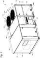
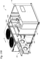
Figure 2 is a front perspective view of an AHU for an HVACR system. -
Figure 3 is partial front perspective view of a front side of the AHU inFigure 2 , accordingly to an embodiment. -
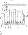
Figure 4 is a partial rear view of a combustion heater in a fan section of the AHU inFigure 2 , according to an embodiment. -
Figure 5 is a partial vertical cross-sectional view of the combustion heater of the AHU as indicated inFigure 2 , according to an embodiment. -
Figure 6 is a perspective view of theslidable tube support 150 and tube support clips for a combustion heater of an AHU, according to an embodiment. -
Figures 7A - 7C show a combustion heater of the ABU inFigure 2 in various positions.Figure 7A is a schematic rear perspective view showing the combustion heater in an installed position, according to an embodiment.Figure 7B is a schematic rear perspective view showing the combustion heater in a partially removed position, according to an embodiment.Figure 7C is a schematic rear perspective view showing the combustion heater in a completely removed position, according to an embodiment. -
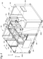
Figure 8 is a rear perspective view of an embodiment of an AHU. -
Figure 9 shows a rear view of a fan assembly and rails for supporting the fan assembly within the AHU ofFigure 8 , according to an embodiment. -
Figure 10 shows a partial top view of the fan assembly in a fan section of the AHU ofFigure 8 , according to an embodiment. -
Figure 11 is a rear perspective exploded view of a sliding block section disposed in a fan section of the AHU ofFigure 8 , according to an embodiment. -
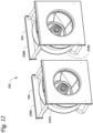
Figure 12 is a top perspective view of an embodiment of a fan assembly for an AHU. -
Figures 13A - 13C show the fan assembly of the ABU inFigure 8 in various positions. -
Figure 13A is a rear perspective view of the ABU with the fan assembly in a partially slidably removed position, according to an embodiment.Figure 13B is a rear perspective view of the ABU with the fan assembly in a completely slidably removed position, according to an embodiment.Figure 13C is a schematic rear perspective view showing the fan assembly in a completely liftably removed position, according to an embodiment. - Like references in the drawings refer to like features.
-
Figure 1 is a schematic diagram of an embodiment of a heating, ventilation, air conditioning, and refrigeration ("HVACR")system 1. TheHVACR system 1 is configured to condition (e.g., heat, cool, dehumidify, and the like) a conditioned space by supplying conditioned air to the conditionedspace 3. The HVACR system can include aductwork ventilation system 5 and an air handling unit ("AHU") 10. TheAHU 10 is connected to theductwork ventilation system 5 that is configured to distribute the conditioned air discharged from theAHU 10 to the conditionedspace 3. Theductwork ventilation system 5 can also return air from the conditionedspace 3 back to theAHU 10. - The air to be conditioned flows through the
AHU 10 from aninlet 12A to theoutlet 12B of theAHU 10. The air is conditioned as it flows from theinlet 12A to theoutlet 12B of the AHU such that conditioned air is discharged from theoutlet 12B. In an embodiment, theAHU 10 is configured to be capable of cooling and heating the air as it flows through theAHU 10. In a heating mode, theAHU 10 heats the air as it flows through theAHU 10. In a cooling mode, theAHU 10 cools the air as it flows through theAHU 10. - The
HVACR system 1 can include arefrigerant circuit 20 to provide cooling. Therefrigerant circuit 20 can include acompressor 22, acondenser 24, anexpander 26, and anevaporator 28. In an embodiment, theheat transfer circuit 1 can be modified to include additional components, such as, for example, an economizer heat exchanger, one or more valve(s), sensor(s) (e.g., a flow sensor, a temperature sensor, and the like), a receiver tank, or the like. The components of theheat transfer circuit 1 are fluidly connected as shown by the dashed lines inFigure 1 . - The
refrigerant circuit 20 operates by known principles of refrigerant compression and expansion to provide cooling. Working fluid (e.g., a refrigerant, a refrigerant blend, or the like) is compressed by thecompressor 10, cooled in thecondenser 24, and then expanded in theexpander 26. The expansion causes the working fluid to cool. The cool working fluid then flows through theevaporator 28. The air flowing through theAHU 10 from theinlet 12A to theoutlet 12B flows through theevaporator 28 separately from the working fluid. The cooler working fluid absorbs heat from the passing air and cools the air. Theevaporator 28 cooling the air passing by/through theevaporator 28. - As the air flows through the
AHU 10 from itsinlet 12A to itsoutlet 12B, the air flows through anevaporator 28 and acombustion heater 14. In a heating mode, theAHU 10 operates thecombustion heater 14 to heat the passing air. In a cooling mode, theAHU 10 can operate therefrigerant circuit 10 for theevaporator 28 to cool the passing air. TheAHU 10 also includes afan 16 to generate air flow through theAHU 10 from itsinlet 12A to itsoutlet 12B. - As shown in
Figure 1 , theAHU 10 can contain components of therefrigerant circuit 20 other thanevaporator 28. TheAHU 10 can include acondenser section 30 that utilizes air to cool one or more components of therefrigerant circuit 20. In an embodiment, theAHU 10 can be configured to operate in a heat pump mode in which theevaporator 28 instead operates as a condenser that heats the air as it flows past. For example, theAHU 10 can include one or more fan(s) 32 that blow ambient air through thecondenser 24 of therefrigerant circuit 20 to cool the working fluid flowing through thecondenser 24. Thecompressor 20 can also be disposed in thecondenser section 30. In an embodiment, the other components of therefrigerant circuit 20 may be located external to the AHU 10 (e.g., in a different AHU, within a building, and the like). TheAHU 10 may also include other components for conditioning the air. TheAHU 10 may include, for example but not limited to, anair filter 32, dehumidifier, humidifier, and the like. -
Figure 2 is a front perspective view of an embodiment of an air handling unit ("AHU") 100 used in an HVACR system. In an embodiment, theAHU 100 can be theAHU 10 in theHVACR 1 shown inFigure 1 . A ductwork ventilation system (e.g., theductwork ventilation system 5 inFigure 1 ) can be connected to theAHU 100 that distributes conditioned air to a conditioned space (e.g., the conditionedspace 5 inFigure 1 ) and then returns the air to theAHU 100 for conditioning. TheAHU 100 includes areturn inlet section 102, afan section 104, and acondensing section 106. TheAHU 100 includes aninlet 108A and anoutlet 108B (obscured inFigure 1 ; shown inFigure 2 ) for the air returning from and being provided to a conditioned space (e.g., the conditionedspace 3 inFigure 1 ). Theinlet 108A andoutlet 108B can be located in the bottom of the AHU 100 (e.g., the bottom of the housing 110). Thesections AHU 100 are discussed in more detail below. - The
AHU 100 includes ahousing 110 with a plurality of sides. As shown inFigure 1 , the AHU includes afirst side 112, asecond side 114, a third side 116 (obscured inFigure 2 ), a fourth side 118 (obscured inFigure 2 ), and afifth side 120. InFigure 2 : thefirst side 112 is the front side, thesecond side 114 is the left side, thethird side 116 is the right side, thefourth side 118 is the rear side, and thefifth side 120 is the top side of theAHU 100. The sides of thehousing 110 have panels (e.g.,panel 126 of thefront side 112,panel 227 of thetop side 120, and the like). In an embodiment, one or more panels can be provided on each side. The panels can be opened to access the interior and one or more interior components of theAHU 100. - The air enters the
AHU 100 through theinlet 108A and is then discharged as conditioned air from theAHU 100 from theoutlet 108B. Thereturn inlet section 102 includes theinlet 108A. Thefan section 104 includes theair outlet 108B. The air flows through theinlet 108A into thereturn inlet section 102, from theinlet section 102 to thefan section 104, through thefan section 104 to theoutlet 108B, and is then discharged from theAHU 100 through theoutlet 108B. The air is conditioned as it flows through theAHU 100 from theinlet 108A to theoutlet 108B. For example, the air is conditioned within thereturn inlet section 102 and thefan section 104. - In a heating mode, combustion gases are used to heat the air as it flows through the
fan section 104. In such a configuration, thefan section 104 can also be referred to as a combustion section. In an embodiment, thereturn inlet section 102 includes acooling heat exchanger 122 of the HVACR system (e.g., theevaporator 28 inFigure 1 ). In a cooling mode, air flows through thecooling heat exchanger 122 as it flows through thereturn inlet section 102 and is cooled by a colder fluid (e.g., expanded refrigerant, chiller water, and the like) separately flowing through thecooling heat exchanger 122. Thereturn inlet section 102 may also be referred to as a cooling section. Thecondenser section 106 can contain a condenser of the refrigerant circuit of the HVACR system (e.g.,condenser 24 inFigure 1 ). Thecondenser section 106 circulates air past the condenser to cool the working fluid as it flows through the condenser. In an embodiment, the HVACR system may utilize acondensing section 106 that is provided in separate second AHU (not shown). For example, theAHU 100 in such an embodiment would include thereturn inlet section 102 and thefan section 104 without the condensingsection 106. -
Figure 3 is partial front perspective view of thefront side 112 of theAHU 100. Apanel 126 of thefront side 112 is opened and removed inFigure 3 . Thepanel 126 covers anopening 128 in thehousing 110 for the fan acombustion heater 130 that extends into thefan section 104 of theAHU 100. In a heating mode, thecombustion heater 130 heats the air as it flows through thefan section 104. - The
combustion heater 130 includes anend plate 132,igniters 134, a plurality of heat exchanger tubes 136 (obscured inFigure 2 ; e.g., shown inFigure 4 ), and afan 138. Theigniters 134 and fan 137 are provided on theend plate 132. Theheat exchanger tubes 136 are disposed in the airflow path through thefan section 104. Theigniters 134 ignite an air and fuel mixture flowing into theheat exchanger tubes 136. The air and fuel mixture can be ignited before entering theheat exchanger tubes 136 or as the mixture flows into theheat exchanger tubes 136. As the hot combustion gas flows through theheat exchanger tubes 136, the air flowing through thefan section 104 absorbs heat from the hot combustion gas through the walls of theheat exchanger tubes 136. The air is heated as it flows through thefan section 104 and past theheat exchanger tubes 136. Thefan 138 directs the air and fuel mixture and/or its resulting combustion gas to flow through theheat exchanger tubes 136. For example, as shown inFigure 3 , thefan 138 can provide suction to the outlets of theheat exchanger tubes 136 to generate flow through theheat exchanger tubes 136. In another embodiment, thefan 138 may be upstream of theignitors 134 and configured to blow the air and gas mixture to theignitors 138. Thefan 138 can be configured to blow the cooled combustion gases out of theAHU 100. - The
combustion heater 130 is configured to be slidably removable from theAHU 100. Thecombustion heater 130 is removed from theAHU 100 by moving through theopening 128 in thehousing 110 in a direction D3. For example, thecombustion heater 130 may be removed by being pulled through theopening 128 in the direction D3. The slidable removal of thecombustion heater 130 is described in more detail below. - The removal of the
combustion heater 130 includes fluidly and electrically decoupling thecombustion heater 130 from the rest of theAHU 100. For example, fluidly decoupling thecombustion heater 130 can include decoupling thecombustion heater 130 from the piping of theAHU 100 that supplies the air and fuel, separately or as a mixture, to thecombustion heater 130. Fluidly decoupling thecombustion heater 130 can also include decoupling the exhaust outlet of the combustion heater 130 (e.g., the outlet vent of the fan 138) from thehousing 110. Electrically decoupling thecombustion exchanger unit 130 from theAHU 100 can include disconnecting one or more electrical wires for the combustion heater 130 (e.g., power supply wire(s), sensor signal wire(s), and the like). - In an embodiment, one or more retaining structures, such as fasteners (e.g., screws, bolts, clamps, and the like), flexible tabs, and the like, may be provided to secure the
end plate 132 to thehousing 110 so as to prevent minor movement and/or accidental movement of thecombustion heater 130. In such an embodiment, the removal of thecombustion heater 130 can include removing such fasteners (e.g., flexing the flexible tab(s), unscrewing the screw(s) and/or bolt(s), removing clamp(s), and the like) to allow the movement and removal of thecombustion heater 130. -
Figure 4 shows a partial rear view of the interior of theAHU 100. In particular,Figure 4 illustrates thecombustion heater 130 disposed in thefan section 104. The arrows F1 illustrate the flow of air through thefan section 104 past theheat exchanger tubes 136 and out through theoutlet 108B. Theheat exchanger tubes 136 generally extend in a direction perpendicular to the flow of air through thefan section 104. For example, theheat exchanger tubes 136 extend from theend plate 132 of thecombustion heater 130 in the direction D3 that extends from the front to the back of theAHU 100, while the air flows in a direction D2 that extends from the top to the bottom of theAHU 100. -
Fan section 104 includes a pair of opposingside walls fan section 104 from theother sections AHU 100. As shown inFigure 4 , theside walls housing 110 of theAHU 100. Thefirst side wall 140 is an internal wall between thefan section 104 and thereturn inlet section 102. Thesecond side wall 142 is between thefan section 104 and thecondenser section 106. Theside walls heat exchanger tubes 136 and towards theoutlet 108B in the bottom of thefan section 104. Theheat exchanger tubes 136 disposed between theside walls side walls AHU 100 to the rear of the AHU 100 (e.g., from thefront side 112 to the rear side 118) and from the bottom of theAHU 100 to the top of the AHU (e.g., from the bottom of the AHU to the top side 120). Thefan section 104 is formed by thefront side 112, therear side 118, and thetop side 120 of thehousing 110 and theside walls - As shown in
Figure 4 , theside walls channel first side wall 140 includes afirst channel 144A and thesecond side wall 142 includes asecond channel 144B. Thechannels fan section 104. For example, thefirst channel 144A has a longitudinal opening that faces thesecond side wall 142, andsecond channel 144A has a longitudinal opening that faces thefirst side wall 140. In combination, the twochannels fan section 104. As shown inFigure 4 , thechannels channels respective side wall front side 112 of the housing 112 (e.g., in the direction D1 inFigure 2 ). - As shown in
Figure 4 , thechannels brackets first bracket 146A is affixed to thefirst side wall 140, and asecond bracket 146B is affixed to thesecond side wall 142. For example, thefirst bracket 146A is affixed to the surface of thefirst wall 140 and thesecond bracket 146B is affixed to the surface of thesecond wall 142. The first andsecond brackets second channels - The
combustion heater 130 includes aslidable tube support 150 that supports theheat exchanger tubes 136 within the interior space of thefan section 104. Theslidable tube support 150 is configured to be slidable along in the depth direction D1 of thefan section 102 for moving thecombustion heater 130 through theopening 128 in the housing 110 (shown inFigure 3 ). Thetube support 150 is slidable/movable relative to thehousing 110. For example, this allows a technician (manually or machine assisted) to pull on thecombustion heater 130 in the direction D3 to slide theentire combustion heater 130 through theopening 128 in thehousing 110. In an embodiment, theopening 128 in thehousing 110 is enlarged to allow removal of thecombustion heater 130 by removing additional panels of thefront side 112 of thehousing 110. Theslidable tube support 150 can be used to partial remove thecombustion heater 130 from the housing 110 (e.g., sliding thecombustion heater 130 only partway through the opening 128) or to completely remove thecombustion heater 130 from theAHU 100 and thehousing 110. For example, the partial removal may be used by a technician to allow for easier repair of thecombustion heater 130, while the full removal can be used for larger repairs and/or for replacement of thecombustion heater 130. - The
slidable tube support 150 includes a retainingmember 152 that is slotted into thechannels member 152 is slidably disposed in thechannels member 152 extends from thefirst channel 144A to thesecond channel 144B. When thecombustion heater 130 is installed in theAHU 100, the retainingmember 152 extends between thefirst side wall 140 thesecond side wall 142. The retainingmember 152 has afirst end 154 and an oppositesecond end 156. Thefirst end 154 is disposed in thefirst channel 144A and thesecond end 156 is disposed in thesecond channel 144B. As the retainingmember 152 is vertically trapped in thechannels member 152 in the vertical direction (e.g., in direction D2, in the opposite direction of the direction D2) is prevented/restricted while being free to move along the length of thechannels Figure 4 , in direction D1 inFigure 2 , in direction D3 inFigure 2 ). Thechannels 144A, 144b configured to limit vertical movement of thetube support 150 while not limiting the movement along the first direction D1 - The retaining
member 152 is rotatable within thechannels combustion heater 130 is configured to pivot on the retainingmember 152. The retainingmember 152 acts as the rotational axis for the pivoting of thecombustion heater 130. For example, thecombustion heater 130 can be swung forwards towards the front side 112 (e.g., in direction D3) to pivot thecombustion heater 130 and angle thecombustion heater 130 at an incline towards the front side 112 (e.g., angled upwards in the direction D3). For example, the combustion heater can be swung backwards towards the rear side 118 (e.g., in direction D1) to pivot thecombustion heater 130 and angle thecombustion heater 130 to decline towards the front side 112 (e.g., angled downwards in the direction D3).Thechannels member 152 through the length of thechannels member 152 is configured to only be removable from thechannels channels channels member 152 cannot be vertically removed from thechannels member 152 from thechannels Figure 4 , thecombustion heater 130 can also include a plurality of adjacent tube support clips 170. The support clips 170 are discussed in more detail below. -
Figure 5 is a partial vertical cross-sectional view of thecombustion heater 130 as indicated inFigure 2 , according to an embodiment. For example,Figure 5 illustrates the interaction between theslidable tube support 150 and theheat exchanger tubes 136. The retainingmember 152 is fastened to one or more of theheat exchanger tubes 136 to prevent the retainingmember 152 from moving relative to theheat exchanger tubes 136. As shown inFigure 5 , the retainingmember 152 can be fastened around a group of theheat exchanger tubes 136. The retainingmember 152 can include a pair ofbrackets 158 that are fastened together with fasteners 160 (e.g., screws, bolts, clamps, and the like). Onebracket 158 disposed above the group ofheat exchanger tubes 136 and thesecond bracket 158 disposed below the group ofheat exchanger tubes 136. Theheat exchanger tubes 136 being pinched between the fastened together pair ofbrackets 158. The group ofheat exchanger tubes 136 held between the pair ofbrackets 158. It should be appreciated that theslidable tube support 150 can be prevented from sliding along theheat exchange tubes 136 in a different manner. For example, theslidable tube support 150 may be affixed to theheat exchange tubes 136 via welding, fasteners, or the like, or theheat exchanger tubes 136 may have exterior projections that prevent thetube support 150 from sliding along the outsides of theheat exchanger tubes 136. - The
slidable tube support 150 also includes avertical support 164 and a plurality ofcontact arms 166. As shown inFigure 5 , thevertical support 164 extends from the retainingmember 152, and thecontact arms 166 each extend outward from thevertical support 164. For example, thecontact arms 166 branch off from thevertical support 164. Thecontact arms 166 are connected to the retainingmember 152 by thevertical support 164. For example, thevertical support 164 is directly connected to the retainingmember 152, and thecontact arms 166 are each directly connected to thevertical support 164. - The
vertical support 164 extends along a column of theheat exchanger tubes 136. As shown inFigure 5 , thevertical support 164 can extend between two adjacent columns of theheat exchanger tubes 136. In an embodiment, thevertical support 164 extend along an outside column ofheat exchanger tubes 136. - The
heat exchanger tubes 136 rest on thecontact arms 166. Eachheat exchanger tube 136 can rest on arespective contact arm 166. In an embodiment, thecontact arms 166 help to hold theheat exchanger tubes 136. For example, the bottom surface of aheat exchanger tube 136 rests on the upper surface of itsrespective contact arm 166. Thecontact arms 166 are prevented from vertically moving by the retainingmember 152 being disposed/slotted in thechannels contact arms 166 vertically remain in place and provide a support surface for resting theheat exchanger tubes 136. Eachcontact arm 166 prevents/limits the downward movement of its respectiveheat exchanger tube 136. - In an embodiment, one or more of the
exchanger tubes 136 may be contacted by just asingle contact arm 166. For example, theheat exchanger tubes 136 in the rightmost column ofheat exchanger tubes 136 inFigure 5 are each in contact withmultiple contact arms 166. In an embodiment, one or more of theheat exchanger tubes 136 may be contacted bymultiple contact arms 166. Theheat exchanger tube 136 can rest on afirst contact arm 166 as discussed above. Asecond contact arm 166 can contact the top of theheat exchanger tube 136 and be configured to prevent upward movement of theheat exchanger tube 136. For example, thesecond contact arm 166 can also provide support to the upper adjacentheat exchanger tube 136. The upper adjacentheat exchanger tube 136 rests on the upper surface of thesecond contact arm 166. - The
combustion heater 130 shown inFigures 4 and5 has asingle tube support 140. However, thecombustion heater 130 in an embodiment may include multiple of thetube support 140. Theheat exchanger tubes 136 are supported within theAHU 100 by only theend plate 130 and the one or more tube support(s) 140. -
Figure 6 shows a perspective view of theslidable tube support 150 and the adjacent tube support clips 170, according to an embodiment. Dashed lines are provided inFigure 6 to illustrate the positions of the leftmost column ofheat exchanger tubes 136. The support clips 170 can help ensure a desired vertical spacing is maintained between adjacent heat exchanger tubes 136 (e.g., vertically adjacent heat exchanger tubes 136). - Each
support clip 170 includes afirst opening 172 and asecond opening 174. Thefirst opening 172 is configured to fit around a firstheat exchanger tube 136, and whilesecond opening 174 is configured to fit around a second adjacentheat exchanger tube 136. In an embodiment, thefirst opening 172 andsecond opening 174 are configured to snap fit around their respectiveheat exchanger tube 136. Thesupport clip 170 also has amiddle portion 176 disposed between its adjacent pairheat exchanger tubes 136. Themiddle portion 176 is configured to restrict movement between the adjacentheat exchanger tubes 136. For example, themiddle portion 176 is a bent portion that acts as a spring that biases the adjacentheat exchanger tubes 136 to a predetermined relative vertical position (e.g., biased to a set predetermined distance between the adjacent heat exchanger tubes 136). - Each
support clip 170 in the plurality of adjacent tube support clips 170 couples a different set of heat exchanger tubes. The support clips 170 can overlap at least oneheat exchanger tube 136. For example, afirst support clip 170A couples a firstheat exchanger tube 136A to a secondheat exchanger tube 136B, and asecond support clip 170B couples the secondheat exchanger tube 136B to athird heat exchanger 136B. - The
slidable tube support 150 inFigures 4 - 6 includes acontact arm 166 for eachheat exchanger tube 136. However, the slidingsupport 150 in an embodiment may not have acontact arm 166 for eachheat exchanger tube 136. In such an embodiment, the support clip(s) 170 can be used to couple aheat exchanger tube 136 without acontact arm 166 to aheat exchanger tube 136 with acontact arm 166. Theslidable tube support 150 can provide support to theheat exchanger tube 136 without acontact arm 166 via the supportedheat exchanger tube 136 and said support clip(s) 170. -
Figures 7A - 7C show thecombustion heater 130 in various positions when being removed from theAHU 100. Dashed lines are provided inFigures 7A and7B to illustrate the sides of thehousing 110 that form thefan section 104 of theAHU 100. -
Figure 7A shows thecombustion heater 130 in a first position. The first position is the position in which thecombustion heater 130 is installed in theAHU 100 and is ready for operation. Thecombustion heater 130 in the installed position is ready for operating to direct combustion gases through theheat exchanger tubes 136 and heats the air as it flows through thefan section 104. The first position can also be referred to as the installed position.Figure 3 also shows thecombustion heater 130 in its installed position. - As shown in
Figure 7A , thechannels front side 112 and therear side 118 of theAHU 100. Each of thechannels front side 112 of theAHU 100. As shown inFigure 7A , each of thechannels respective side wall front side 112 of theAHU 100. Theend 147 of eachchannels front side 112 is open. Thebrackets fan section 104. -
Figure 7B shows thecombustion heater 130 in a second position. The second position is a position in which thecombustion heater 130 is partially slidably removed from theAHU 100. For example, thecombustion heater 130 inFigure 7A is slidably moved (e.g., pulled) through theopening 128 in thefront side 112 of theAHU 100 to reach the second position shown inFigure 7A . Thecombustion heater 130 is slidably moved in the direction D3 from the first position (shown inFigure 7A ) into the second position (shown inFigure 7B ). The second position may allow, for example, a technician to more easily access and/or work on thecombustion heater 130. -
Figure 7C shows thecombustion heater 130 in a third position. The third position is a position in which thecombustion heater 130 is completely removed from theAHU 100. For example, thecombustion heater 130 inFigures 7A and7B is slidably moved (e.g., pulled) through theopening 128 in thefront side 112 of theAHU 100 to reach the third position shown inFigure 7C . Thecombustion heater 130 slidably moved in the direction D3 from the second position (shown inFigure 7B ) into the second position (shown inFigure 7C ). In the removed position (shown in Figure 7D), thecombustion heater 130 is completely separated from theAHU 100. - In removing the
combustion heater 130 from the AHU 100 (e.g., moving thecombustion heater 130 into the completely removed position shown inFigure 7C ), theslidable tube support 150 slides out of thechannels member 152 sliding out of theends 147 of thechannels combustion heater 130 from theAHU 100 by simply pulling it in the third direction D3 from theAHU 100. Theslidable tube support 150 is configured to support the installed combustion heater 130 (e.g., vertically support theheat exchanger tubes 136 within the fan section 104) while also allowing slidable movement and removal ofcombustion heater 130 from theAHU 100. In an embodiment, theslidable tube support 150 is slidable in the depth direction D3 such that is does not restrict movement of thecombustion heater 130 along the depth direction D3. - In an embodiment, a slidable tube support system for an
AHU 100 includes one or more of the slidable tube supports 150. In an embodiment, the slidable tube support system for anAHU 100 includes one or more of the slidable tube supports 150 and one or more adjacent tube support clips 170. For example, the slidable tube support system may include a plurality of the adjacent tube support clips 170. -
Figure 8 is a rear perspective view of an embodiment of anAHU 100. Apanel 226 of therear side 118 is opened and removed inFigure 9 . Thepanel 226 covers anopening 228 in therear side 118 ofhousing 110 for thefan section 104 of theAHU 100. Theopening 228 in thehousing 228 can be for an upper portion of thefan section 104. Thetop side 120 of thehousing 110 of the AHU 100 (e.g.,top side 120 inFigure 2 ) inFigure 8 is also removed for illustration. For example, a panel 227 (shown inFigure 2 ) of thetop side 120 is opened and removed inFigure 8 . Thepanel 227 covers anopening 229 in thetop side 120 of thehousing 110 for thefan section 104 of theAHU 100. In particular, theopening 229 is for the top of thefan section 104. - The
AHU 100 includes afan assembly 230. Thefan assembly 230 operates to generate air flow through thehousing 110 from the inlet 108Ato theoutlet 108B (obscured inFigure 8 ), as discussed above. Thefan assembly 230 one or more fan(s) 232 and afan frame 234. The fan(s) 232 affixed to thefan frame 234. For example, thefan frame 234 provides a support frame for the fan(s) 232. As shown inFigure 8 , the fan(s) of thefan assembly 230 are radial fan(s). A radial fan has an axial inlet and at least one radial outlet. The radial fan axially suctioning air into its blade and discharging the air in one or more radial direction(s). The shape of thefan section 104 can direct the air downward towards theheat exchanger tubes 136 and theoutlet 108B. - The fan(s) 232 are configured to suction air from the
inlet section 102 into thecombustion suction 104. As shown inFigure 8 , thefan frame 234 can also define aninlet 235 for each fan(s) 232 to suction air from theinlet section 102. During operation of theAHU 100, fan(s) 232 generates the flow of air through theinlet section 102 and thefan section 104 as discussed above. In particular, thefan assembly 230 can be configured to blow air so that the air flows downward from thefan assembly 230 and across theheat exchanger tubes 136 of the combustion heater 130 (e.g., air flows downward in direction D2 across theheat exchanger tubes 136 as shown inFigure 4 ). For example, the suction of the fan(s) 232 pulls air through theinlet 108A (obscured inFigure 8 ) intoinlet section 102 and blows the air past theheat exchanger tubes 136 and out through theoutlet 108B in thefan section 104. - The
housing 110 includes a pair ofrails fan assembly 230. Therails fan section 104. Each of therails front side 112 and therear side 118 of thehousing 110. For example, therails opening 228 into thefan section 104. Thefan frame 234 includes a pair ofgrooves grooves rails fan assembly 230 to thehousing 110. -
Figure 8 shows thefan assembly 230 in a first position. The first position is the installed position of thefan assembly 230. Thefan assembly 230 in its installed position is ready for operating to blow air from theinlet section 102 downward towards theheat exchanger tubes 136 of thecombustion heater 130. Thefan assembly 230 is configured to be both slidably and liftably removable from theAHU 100 as discussed below. For example, the disposition of thegrooves fan assembly 230 to therails fan assembly 230 within theAHU 100 while also allowing lifting and horizontal sliding of thefan assembly 230 sufficient to remove the fan assembly from theAHU 100. In an embodiment, theAHU 100 can include one or more the sliding block(s) 270. The sliding block(s) 270 are discussed in more detail below. -
Figure 9 shows a rear view of thefan assembly 230 disposed on therails top side 120 of thehousing 110 that extends along thefan section 104 is illustrated in dashed lines inFigure 9 for illustration purposes. Thefan assembly 230 hangs from therails fan assembly 230 is slidable on therails grooves rails fan assembly 230 is slidably supported withinAHU 100. The configuration of thegrooves rails fan assembly 230 to be lifted off of therails - As shown in
Figure 9 , thefan 232 includes anelectrical motor 233. Theelectrical motor 233 that drives thefan 232. TheAHU 100 can include one or more electrical wires (e.g., power supply wire(s), signal wire(s), and the like) (not shown) for operating the fan(s) 232. The removal of thefan assembly 230 can include electrically decoupling thefan assembly 230 from the rest of theAHU 100. For example, electrically decoupling thefan assembly 230 from theAHU 100 can include disconnecting the electrical wire(s) for thecombustion heater 130. - As shown in
Figure 9 , each of therails top side 120 of thehousing 110. For example, therails rails Figure 9 project directly upward. In an embodiment, rails 250A, 250B may project upwards at an angle. In an embodiment, thegrooves fan assembly 230 are slotted onto therails housing 110. For example, afirst groove 236A is slotted onto afirst rail 250A and asecond groove 236B is slotted onto thesecond rail 250A. - As shown in
Figure 9 , thegrooves top side 120 of thehousing 110. For example, thegrooves grooves Figure 9 face directly downwards. In an embodiment, thegrooves groove grooves Figure 9 are enclosed on at least three sides. For example, the space in thegrooves Figure 9 are enclosed by a first side wall that extends upwardly, a second side that extends outwardly from the first side, and a third side that extends downwardly from the second side. This provides thegrooves grooves rails rails grooves rails fan assembly 230 to prevent therails - In an embodiment, a
groove 236A can be enclosed on just two sides. For example, thegrooves groove fan frame 234. - The
fan assembly 230 is supported within thehousing 110 so as to be liftably removable. Thefan assembly 230 has a configuration that allows for thefan assembly 230 in its install position to be lifted (e.g., moved vertically upward in direction D4) out of theAHU 100 and itshousing 110. The liftably removable configuration of thefan assembly 230 allows for the fan assembly to be lifted from its install position to a position entirely outside of the AHU and itshousing 110. When thefan assembly 230 is to be removed (e.g., for repair, testing, replacement, and the like), thefan assembly 230 is configured from its installed position to liftable/movable in the upward direction D4 to pass through theopening 229 in thetop side 120 of thehousing 110 to be entirely outside of theAHU 100 and itshousing 110. -
Figure 10 shows a partial top view of thefan assembly 230 disposed in thefan section 104, according to an embodiment. The general position of theheat exchanger tubes 136 is schematically illustrated with dashed lines inFigure 10 . The general position of theoutlet 108A is also illustrated inFigure 10 . - As similarly discussed above, the
grooves fan assembly 230 are slidably disposed on therails housing 110. Thegrooves rails fan assembly 230 is slidable along therails fan assembly 230 is configured to be slidable along the length L of therails housing 110. Thefan assembly 230 slides along therails fan assembly 230 through theopening 228 inhousing 110. - As shown in
Figure 10 , thegrooves fan frame 234. For example, thefirst groove 236A is located along the rear of thefan frame 234 and thesecond groove 236B is disposed along the front of thefan frame 234. Thegrooves Figure 10 have multiple sections. For example, thefirst groove 236A is non-continuous and has multiple sections disposed on thefirst rail grooves - The
fan assembly 230 is slidably removable by having a configuration that allows for thefan assembly 230 to be slide from its installed position to a position outside of theAHU 100 and itshousing 110. For example, thefan assembly 230 from its installed position is slidable in the horizontal direction (e.g., in the direction D1) to an extent that allows for thefan assembly 230 to be moved entirely outside of theAHU 100 and itshousing 110. - In an embodiment, the
AHU 100 may include one or more slidingblock 270. The sliding block(s) 270 restrict the sliding movement of thefan assembly 230 along therails block 270 is disposed in the sliding path of thefan assembly 230. The slidingblock 270 limits the sliding of thefan assembly 230 along therails groove 236A contacts the slidingblock 270 and is stopped from sliding further in the direction D1. As shown inFigure 10 , a sliding block 270A can be provided along one of therails fan assembly 230 and theopening 228 and/or between sections of one of thegrooves - Operation of the
AHU 100 can shake thefan assembly 230. The operation of the fan(s) 232 can also apply directional forces to thefan assembly 230. For example, operation of the fan(s) can apply a force in the first direction D1 to thefan assembly 230. The sliding block(s) 270 can be used to limit/prevent sliding of thefan assembly 230 in their installed position during operation of theAHU 100. For example, the sliding block(s) 270 preventing incidental sliding of thefan assembly 230 not related to removal of the fan assembly 230 (e.g., forces not applied by a technician (directly or mechanically) for sliding the fan assembly 230). In an embodiment, the sliding removal of thefan assembly 230 can include detaching the slide blocks 270 to allow the full sliding movement and removal of thefan assembly 230. -
Figure 11 is a rear perspective exploded view of a slidingblock 270 for thefan assembly 230, according to an embodiment. The slidingblock 270 is configured to be detachably affixed to thehousing 110 and/or to thefan assembly 230. The slidingblock 270 can have afirst side 272 that is detachably affixed to thehousing 110. As shown inFigure 11 , thefirst side 272 may be detachably affixed to the one of therails block 270 can have asecond side 274 that is detachably affixed to thefan assembly 230. For example, thesecond side 274 is detachably affixed to thefan frame 234 via a fastener 276 (e.g., screw, bolt, clamp, and the like), coupling, or the like. When thefan assembly 230 is to be removed, the slidingblock 270 is detached from thefan assembly 230 and/or thehousing 110. In an embodiment, sliding removal of thefan assembly 230 can include removing one or more of thefasteners 276 to detach the sliding block 270 (e.g., unscrewing, pulling out, removing, and the like) fromfan assembly 230 and/or thehousing 110. -
Figure 12 shows the separation of thefan assembly 230. In an embodiment, thefan frame 234 of thefan assembly 230 is configured to be separable into multipleseparate portions Figure 12 . Each of theportions fan 232. Theportions fan frame 234 is separable into afirst frame portion 238A that includes afirst fan 232A and asecond frame portion 238B that includes asecond fan 232B. Thefan assembly 230 is separable into two portions inFigure 12 . In an embodiment, thefan assembly 230 may include more than twofans 232 and be separable into more than twoframe portions fan assembly 230 in an embodiment may include three ormore fans 232 and be separable into three or more portions. -
Figures 13A - 13C show thefan assembly 230 in various positions during removal from theAHU 100.Figures 13A and13B shows thefan assembly 230 when slidably removed from theAHU 100.Figure 13C shows thefan assembly 230 when liftably removed from theAHU 100. As noted above,Figure 8 shows thefan assembly 230 in the first position, which is its installed position. -
Figure 13A shows thefan assembly 230 in a second position. The second position is a position in whichfan assembly 230 is partially slidably removed from theAHU 100. For example,fan assembly 230 inFigure 8 is slidably moved (e.g., pulled) through theopening 228 in therear side 118 of theAHU 100 to reach its second position as shown inFigure 13A . Thefan assembly 230 is slidably moved along therails Figure 8 ) into the second position (shown inFigure 13A ). The second position may allow, for example, a technician to more easily access and/or work on thefan assembly 230. - As shown in
Figure 13A , the first fan portion 238 is positioned outside of theAHU 100 when thefan assembly 230 is in the second position. In an embodiment, the second position allows for the first fan portion 238 to be detached and separated from theAHU 100. For example, thefirst fan portion 238A is disposed outside theAHU 100 which can allow thefirst fan portion 238A to be separated from the rest of the fan assembly 230 (e.g., can allow thefirst fan portion 238A to be separated from thesecond fan portion 238B). The second position may advantageously allow, for example, a technician to remove thefirst fan portion 238A when there is limited room along therear side 118 of the housing 110 (e.g., therear side 118 is close to the side of a building, another AHU, or the like). -
Figure 13B shows thefan assembly 230 in a third position. The third position is a position in whichfan assembly 230 is completely slidably removed from theAHU 100. For example, thefan assembly 230 inFigure 8 and/orFigure 13A is slidably moved (e.g., pulled) through theopening 228 in therear side 118 of theAHU 100 to reach the third position shown inFigure 13B . Thefan assembly 230 slidably moved in the direction D1 from the first position (shown inFigure 8 ) to the third position (shown inFigure 13B ). Thefan assembly 230 reaching and being moved from the second position (shown inFigure 13A ) as thefan assembly 230 is moved from the first position (shown inFigure 8 ) to the third position (shown inFigure 13B ). The second position inFigure 13A can be an example of an intermediate position between the installed position and the completely slidably removed position. In the removed position (shown inFigure 13B ), thefan assembly 230 is completely separated from theAHU 100. - The
fan assembly 230 is configured to slide through anopening 228 in therear side 118 ofAHU 100. In an embodiment, the sliding direction/removal direction of thefan assembly 230 may be invested. For example, theAHU 100 in an embodiment may be configured to have thefan assembly 230 configured to be slidably move through an opening in thefront side 112 ofhousing 110 instead of therear side 118. -
Figure 13C shows thefan assembly 230 in a fourth position. The fourth position inFigure 13C is a position in whichfan assembly 230 is completely liftably removed from theAHU 100. The fourth position can be referred to as a completely liftably removed position. For example,fan assembly 230 in the installed position (as shown inFigure 8 ) is moved upwardly (e.g., lifted, pulled upwards) through theopening 229 in thetop side 120 of theAHU 100 to reach the fourth position shown inFigure 13C . Thefan assembly 230 is lifted/moved in the direction D4 from the first position (shown inFigure 8 ) into the fourth position (shown inFigure 13C ). - When
fan assembly 230 is configured to be capable of being both slidably removable and liftably removable from theAHU 100. For example, thefan assembly 230 in the first position (as shown inFigure 8 ) is capable of sliding out of theAHU 100 to be removed and is capable of being lifted out of theAHU 100 to be removed. This duel removability of thefan assembly 230 advantageously allows removal through two different sides ofAHU 230. This can be advantageous when one side of an installed AHU is close to another object (e.g., a portion of a building, another AHU, and the like) that does not allow for removal through said side. - In an embodiment, the removable configuration of the
fan assembly 104 may be employed inAHU 100 that does not include a combustion heater. For example, in such an embodiment, theAHU 100 may be configured to utilize a non-combustion type of heater or to not have a heating mode. In an embodiment, the removable configuration of thecombustion unit 130 may be employed in anAHU 100 that does not utilize the liftably and slidably removable fan assembly. In such an embodiment, theAHU 100 may employ a conventional fan configuration for directing air through thefan section 104. - Any of aspects 1 - 11 can be combined with any of aspects 12 - 18.
-
Aspect 1. An air handling unit for a heating, ventilation, air conditioning, and refrigeration system, the AHU comprising: a housing containing a combustion section, the housing including a first side having an opening for the combustion section, the combustion section having a first side wall with a first channel and a second side wall with a second channel, the first side wall disposed opposite of the second side wall; a combustion heater disposed within the housing, the combustion heater including: an end plate, heat exchanger tubes extending from the end plate and into the combustion section, and a tube support supporting the heat exchanger tubes within the combustion section, the tube support slidably disposed in the first channel and the second channel, wherein the tube support configured to slidably move through the first channel and the second channel in a first direction that moves the combustion heater through the opening in the housing. - Aspect 2. The air handling unit of
aspect 1, wherein the tube support configured to slidably move in the first direction through and from the first channel and the second channel such that the combustion heater is entirely moved through the opening in the housing. -
Aspect 3. The air handling unit of any one ofAspects 1 or 2, wherein the first channel and the second channel each have an open end, the tube support having a retaining member slidably disposed in the first channel and the second channel, and movement of the retaining member in the first direction through the open ends of the first channel and the second channel separates the combustion heater from the housing. - Aspect 4. The air handling unit of any one of Aspects 1 - 3, wherein the first channel and the second channel do not limit movement of the tube support in the first direction.
-
Aspect 5. The air handling unit of any one of Aspects 1 - 4, wherein the tube support includes a retaining member, the retaining member having a first end disposed in the first channel and a second end disposed in the second channel. - Aspect 6. The air handling unit of
Aspect 5, wherein tube support includes a vertical support extending from the retaining member, and a plurality of contact arms each extending from the vertical support, the heat exchanger tubes each resting on a respective one of the plurality of contact arms. - Aspect 7. The air handling unit of Aspect 6, wherein each of the contact arms extending between a vertically adjacent pair of the heat exchanger tubes.
- Aspect 8. The air handling unit of any one of Aspects 1 - 7, wherein the tube support vertically supports the heat exchanger tubes within the combustion section.
- Aspect 9. The air handling unit of any one of Aspects 1 - 8, wherein the first channel and the second channel restricting vertical movement of the tube support while allowing the tube support to move in the first direction.
-
Aspect 10. The air handling unit of any one of Aspects 1 - 9, the first channel and the second channel formed by a pair of brackets provided on opposite walls of the combustion section. - Aspect 11. The air handling unit of any one of Aspects 1 - 10, further comprising: one or more support clips, each of the support clips fitted around a vertically adjacent pair of the heat exchanger tubes.
- Aspect 12. An air handling unit for a heating, ventilation, air conditioning, and refrigeration system, the air handling unit comprising: a housing containing a combustion section, the housing including: a first side with a first opening for the combustion section, a top side with a second opening for the combustion section, and a pair of rails disposed in the combustion section, a fan assembly disposed in the combustion section, the fan assembly including one or more fans and a pair of grooves, the pair of grooves slidably disposed on the pair of rails, wherein the fan assembly is configured to be both slidably removable from the AHU through the first opening in the housing and liftably removable from the AHU through the second opening in the housing.
- Aspect 13. The air handling unit of Aspect 12, wherein the fan assembly is configured to be: slidable along the pair of rails in a first direction to move the fan assembly through the first opening, and liftable from the pair of rails in a second direction to move the fan assembly through the second opening, the first direction and second direction being different.
-
Aspect 14. The air handling unit of any one of Aspects 12 or 13, wherein the second direction is an upward direction. - Aspect 15. The air handling unit of any one of Aspects 12 - 14, wherein the pair of grooves includes a first groove disposed on a first side of the fan assembly and a second groove disposed on a second side of the fan assembly opposite the first side.
-
Aspect 16. The air handling unit of any one of Aspects 12 - 15, wherein the pair of grooves face downward and the pair of rails project upwards. - Aspect 17. The air handling unit of any one of Aspects 12 - 16, wherein the fan is a radial fan.
- Aspect 18. The air handling unit of any one of Aspects 12 - 17, further comprising: a heater disposed in the fan section, the one or more fans of the fan assembly configured to blow air towards the heater.
- The present application is a divisional application of
EP21217753.9 EP21217753.9 -
Statement 1. An air handling unit (AHU) for a heating, ventilation, air conditioning, and refrigeration system, the air handling unit comprising:- a housing containing a combustion section, the housing including: a first side with a first opening for the combustion section, a top side with a second opening for the combustion section, and a pair of rails disposed in the combustion section,
- a fan assembly disposed in the combustion section, the fan assembly including one or more fans and a pair of grooves, the pair of grooves slidably disposed on the pair of rails,
- wherein the fan assembly is configured to be both slidably removable from the AHU through the first opening in the housing and liftably removable from the AHU through the second opening in the housing.
- Statement 2. The AHU of
Statement 1, wherein the fan assembly is configured to be:- slidable along the pair of rails in a first direction to move the fan assembly through the first opening, and
- liftable from the pair of rails in a second direction to move the fan assembly through the second opening, the first direction and second direction being different.
-
Statement 3. The AHU of Statement 2, wherein the second direction is an upward direction. - Statement 4. The AHU of any one of Statements 1 - 3, wherein the pair of grooves includes a first groove disposed on a first side of the fan assembly and a second groove disposed on a second side of the fan assembly opposite the first side.
-
Statement 5. The AHU of any one of Statements 1 - 4, wherein the pair of grooves face downward and the pair of rails project upwards. - Statement 6. The AHU of any one of Statements 1 - 5, wherein the fan is a radial fan.
- Statement 7. The AHU of any one of Statements 1 - 6, further comprising:
a heater disposed in the fan section, the one or more fans of the fan assembly configured to blow air towards the heater. - Statement 8. An air handling unit (AHU) for a heating, ventilation, air conditioning, and refrigeration system, the air handling unit comprising:
- a housing containing a combustion section, the housing including a first side having an opening for the combustion section, the combustion section having a first side wall with a first channel and a second side wall with a second channel, the first side wall disposed opposite of the second side wall;
- a combustion heater disposed within the housing, the combustion heater including:
- an end plate,
- heat exchanger tubes extending from the end plate and into the combustion section, and
- a tube support supporting the heat exchanger tubes within the combustion section, the tube support slidably disposed in the first channel and the second channel, wherein
- the tube support configured to slidably move through the first channel and the second channel in a first direction that moves the combustion heater through the opening in the housing.
- Statement 9. The AHU of Statement 8, wherein the tube support configured to slidably move in the first direction through and from the first channel and the second channel such that the combustion heater is entirely moved through the opening in the housing.
-
Statement 10. The AHU of any one of Statements 8 and 9, wherein the first channel and the second channel each have an open end, the tube support having a retaining member slidably disposed in the first channel and the second channel, and movement of the retaining member in the first direction through the open ends of the first channel and the second channel separates the combustion heater from the housing. - Statement 11. The AHU of any one of Statements 8 - 10, wherein the tube support includes a retaining member, the retaining member having a first end disposed in the first channel and a second end disposed in the second channel.
- Statement 12. The AHU of Statement 11, wherein tube support includes a vertical support extending from the retaining member, and a plurality of contact arms each extending from the vertical support, the heat exchanger tubes each resting on a respective one of the plurality of contact arms.
- Statement 13. The AHU of Statement 12, wherein each of the contact arms extends between a vertically adjacent pair of the heat exchanger tubes, and the tube support vertically supports the heat exchanger tubes within the combustion section.
-
Statement 14. The AHU of any one of Statements 8 - 13, wherein the first channel and the second channel formed by a pair of brackets provided on opposite walls of the combustion section, the first channel and the second channel restricting vertical movement of the tube support while allowing the tube support to move in the first direction. - Statement 15. The AHU of any one of Statements 8 - 13, further comprising:
one or more support clips, each of the support clips fitted around a vertically adjacent pair of the heat exchanger tubes. - The examples disclosed in this application are to be considered in all respects as illustrative and not limitative. The scope of the invention is indicated by the appended claims rather than by the foregoing description; and all changes which come within the meaning and range of equivalency of the claims are intended to be embraced therein.
Claims (7)
- An air handling unit (AHU) for a heating, ventilation, air conditioning, and refrigeration system, the air handling unit comprising:a housing containing a fan section, the housing including: a first side with a first opening for the fan section, a top side with a second opening for the fan section, and a pair of rails disposed in the fan section; anda fan assembly disposed in the fan section, the fan assembly including one or more fans and a pair of grooves, the pair of grooves slidably disposed on the pair of rails,wherein the fan assembly is configured to be both slidably removable from the AHU through the first opening in the housing and liftably removable from the AHU through the second opening in the housing.
- The AHU of claim 1, wherein the fan assembly is configured to be:slidable along the pair of rails in a first direction to move the fan assembly through the first opening, andliftable from the pair of rails in a second direction to move the fan assembly through the second opening, the first direction and the second direction being different.
- The AHU of claim 2, wherein the second direction is an upward direction.
- The AHU of any one of claims 1 - 3, wherein the pair of grooves includes a first groove disposed on a first side of the fan assembly and a second groove disposed on a second side of the fan assembly opposite the first side.
- The AHU of any one of claims 1 - 4, wherein the pair of grooves face downward and the pair of rails project upwards.
- The AHU of any one of claims 1 - 5, wherein the one or more fans include a radial fan
- The AHU of any one of claims 1 - 6, further comprising:
a heater disposed in the housing, the one or more fans of the fan assembly configured to blow air towards the heater.
Applications Claiming Priority (2)
| Application Number | Priority Date | Filing Date | Title |
|---|---|---|---|
| US17/139,746 US11927364B2 (en) | 2020-12-31 | 2020-12-31 | Air handling unit |
| EP21217753.9A EP4023958B1 (en) | 2020-12-31 | 2021-12-24 | Air handling unit |
Related Parent Applications (1)
| Application Number | Title | Priority Date | Filing Date |
|---|---|---|---|
| EP21217753.9A Division EP4023958B1 (en) | 2020-12-31 | 2021-12-24 | Air handling unit |
Publications (2)
| Publication Number | Publication Date |
|---|---|
| EP4538606A2 true EP4538606A2 (en) | 2025-04-16 |
| EP4538606A3 EP4538606A3 (en) | 2025-06-25 |
Family
ID=79025095
Family Applications (2)
| Application Number | Title | Priority Date | Filing Date |
|---|---|---|---|
| EP21217753.9A Active EP4023958B1 (en) | 2020-12-31 | 2021-12-24 | Air handling unit |
| EP25161552.2A Pending EP4538606A3 (en) | 2020-12-31 | 2021-12-24 | Air handling unit |
Family Applications Before (1)
| Application Number | Title | Priority Date | Filing Date |
|---|---|---|---|
| EP21217753.9A Active EP4023958B1 (en) | 2020-12-31 | 2021-12-24 | Air handling unit |
Country Status (3)
| Country | Link |
|---|---|
| US (2) | US11927364B2 (en) |
| EP (2) | EP4023958B1 (en) |
| CN (1) | CN114688648A (en) |
Families Citing this family (3)
| Publication number | Priority date | Publication date | Assignee | Title |
|---|---|---|---|---|
| US11592215B2 (en) | 2018-08-29 | 2023-02-28 | Waterfurnace International, Inc. | Integrated demand water heating using a capacity modulated heat pump with desuperheater |
| US11927364B2 (en) * | 2020-12-31 | 2024-03-12 | Trane International Inc. | Air handling unit |
| KR20230065824A (en) * | 2021-11-05 | 2023-05-12 | 엘지전자 주식회사 | Gas furnace and air conditioner comprising it |
Family Cites Families (11)
| Publication number | Priority date | Publication date | Assignee | Title |
|---|---|---|---|---|
| US20020092516A1 (en) * | 2001-01-17 | 2002-07-18 | Laurent Gierula | Flexible gas-fired heat exchanger system |
| US20050194003A1 (en) | 2003-12-09 | 2005-09-08 | Paulsen Frederick D. | Furnace distribution blower without a blower housing |
| US20080163805A1 (en) | 2007-01-10 | 2008-07-10 | Johnson Controls Technology Company | Removable casing flange/insulation retainer |
| US7506684B2 (en) | 2007-06-20 | 2009-03-24 | Exxonmobil Research & Engineering Company | Anti-vibration tube support with locking assembly |
| US20120085334A1 (en) | 2010-10-07 | 2012-04-12 | Carrier Corporation | Furnace assembly |
| US10801746B2 (en) | 2014-04-07 | 2020-10-13 | Trane International Inc. | Protective housing structure |
| US10006661B2 (en) * | 2014-11-07 | 2018-06-26 | Trane International Inc. | Furnace |
| US9683735B2 (en) | 2014-12-18 | 2017-06-20 | The Babcock & Wilcox Company | System and device for supporting horizontal boiler tubes |
| US20160209055A1 (en) | 2015-01-20 | 2016-07-21 | Allied Air Enterprises Llc | Systems and methods for a heating and cooling unit and components thereof |
| US20160216004A1 (en) | 2015-01-23 | 2016-07-28 | Heatco, Inc. | High efficiency, high turndown furnace system |
| US11927364B2 (en) * | 2020-12-31 | 2024-03-12 | Trane International Inc. | Air handling unit |
-
2020
- 2020-12-31 US US17/139,746 patent/US11927364B2/en active Active
-
2021
- 2021-12-24 EP EP21217753.9A patent/EP4023958B1/en active Active
- 2021-12-24 EP EP25161552.2A patent/EP4538606A3/en active Pending
- 2021-12-30 CN CN202111652327.3A patent/CN114688648A/en active Pending
-
2024
- 2024-03-11 US US18/601,275 patent/US12429248B2/en active Active
Also Published As
| Publication number | Publication date |
|---|---|
| US11927364B2 (en) | 2024-03-12 |
| US12429248B2 (en) | 2025-09-30 |
| US20240219070A1 (en) | 2024-07-04 |
| EP4538606A3 (en) | 2025-06-25 |
| CN114688648A (en) | 2022-07-01 |
| US20220205683A1 (en) | 2022-06-30 |
| EP4023958B1 (en) | 2025-03-05 |
| EP4023958A1 (en) | 2022-07-06 |
Similar Documents
| Publication | Publication Date | Title |
|---|---|---|
| US12429248B2 (en) | Air handling unit | |
| EP2502002B1 (en) | Condenser assemblies for heating, ventilating, air conditioning, and refrigeration systems | |
| US10852071B2 (en) | Method of operating an energy recovery system | |
| CN102252369A (en) | Vertical air conditioner and method for removing accumulated water on electric heater therein | |
| JP5109591B2 (en) | Humidity control device | |
| US8827169B2 (en) | Humidity control apparatus | |
| EP3961111B1 (en) | Ceiling-embedded indoor unit and air-conditioning device | |
| CN222836985U (en) | Air duct machine | |
| CN116086014A (en) | Air handling unit with box-type air deflector and method for disassembling combustion heater therein | |
| KR100945627B1 (en) | Air conditioner evaporator unit and fan coil | |
| KR20090002732U (en) | Air conditioner | |
| CN223610240U (en) | air conditioner outdoor unit | |
| CN222811847U (en) | Air conditioner outdoor unit | |
| CN222392975U (en) | Air duct machine | |
| CN222417722U (en) | Air duct machine | |
| CN217892457U (en) | Air conditioner evaporator unit, air conditioner and operation machine | |
| CN223610241U (en) | Air conditioner outdoor unit | |
| CN222811846U (en) | Air conditioner outdoor unit | |
| CN222438064U (en) | Air duct machine | |
| KR100934559B1 (en) | Fan Coils for Air Conditioner Evaporator Units and Air Conditioning Systems | |
| JPH0718906Y2 (en) | Integrated air conditioner | |
| JP2004347255A (en) | Air conditioning indoor unit and air conditioner | |
| WO2026083543A1 (en) | Indoor unit for air conditioner and air conditioner | |
| US20200363080A1 (en) | Intake hood system for an hvac unit | |
| AU2008100094A4 (en) | Airconditioning arrangement |
Legal Events
| Date | Code | Title | Description |
|---|---|---|---|
| PUAI | Public reference made under article 153(3) epc to a published international application that has entered the european phase |
Free format text: ORIGINAL CODE: 0009012 |
|
| STAA | Information on the status of an ep patent application or granted ep patent |
Free format text: STATUS: THE APPLICATION HAS BEEN PUBLISHED |
|
| AC | Divisional application: reference to earlier application |
Ref document number: 4023958 Country of ref document: EP Kind code of ref document: P |
|
| AK | Designated contracting states |
Kind code of ref document: A2 Designated state(s): AL AT BE BG CH CY CZ DE DK EE ES FI FR GB GR HR HU IE IS IT LI LT LU LV MC MK MT NL NO PL PT RO RS SE SI SK SM TR |
|
| REG | Reference to a national code |
Ref country code: DE Ref legal event code: R079 Free format text: PREVIOUS MAIN CLASS: F24F0003000000 Ipc: F24H0003080000 |
|
| PUAL | Search report despatched |
Free format text: ORIGINAL CODE: 0009013 |
|
| AK | Designated contracting states |
Kind code of ref document: A3 Designated state(s): AL AT BE BG CH CY CZ DE DK EE ES FI FR GB GR HR HU IE IS IT LI LT LU LV MC MK MT NL NO PL PT RO RS SE SI SK SM TR |
|
| RIC1 | Information provided on ipc code assigned before grant |
Ipc: F24F 3/00 20060101ALI20250519BHEP Ipc: F24H 9/14 20060101ALI20250519BHEP Ipc: F24H 9/1881 20220101ALI20250519BHEP Ipc: F24H 9/06 20060101ALI20250519BHEP Ipc: F24H 9/02 20060101ALI20250519BHEP Ipc: F24H 3/08 20220101AFI20250519BHEP |
|
| STAA | Information on the status of an ep patent application or granted ep patent |
Free format text: STATUS: REQUEST FOR EXAMINATION WAS MADE |
|
| 17P | Request for examination filed |
Effective date: 20260102 |