EP4538604A1 - Outdoor unit - Google Patents
Outdoor unit Download PDFInfo
- Publication number
- EP4538604A1 EP4538604A1 EP23835138.1A EP23835138A EP4538604A1 EP 4538604 A1 EP4538604 A1 EP 4538604A1 EP 23835138 A EP23835138 A EP 23835138A EP 4538604 A1 EP4538604 A1 EP 4538604A1
- Authority
- EP
- European Patent Office
- Prior art keywords
- light
- substrate
- led
- light source
- outdoor unit
- Prior art date
- Legal status (The legal status is an assumption and is not a legal conclusion. Google has not performed a legal analysis and makes no representation as to the accuracy of the status listed.)
- Pending
Links
Images


Classifications
-
- F—MECHANICAL ENGINEERING; LIGHTING; HEATING; WEAPONS; BLASTING
- F21—LIGHTING
- F21V—FUNCTIONAL FEATURES OR DETAILS OF LIGHTING DEVICES OR SYSTEMS THEREOF; STRUCTURAL COMBINATIONS OF LIGHTING DEVICES WITH OTHER ARTICLES, NOT OTHERWISE PROVIDED FOR
- F21V33/00—Structural combinations of lighting devices with other articles, not otherwise provided for
-
- F—MECHANICAL ENGINEERING; LIGHTING; HEATING; WEAPONS; BLASTING
- F24—HEATING; RANGES; VENTILATING
- F24F—AIR-CONDITIONING; AIR-HUMIDIFICATION; VENTILATION; USE OF AIR CURRENTS FOR SCREENING
- F24F1/00—Room units for air-conditioning, e.g. separate or self-contained units or units receiving primary air from a central station
- F24F1/06—Separate outdoor units, e.g. outdoor unit to be linked to a separate room comprising a compressor and a heat exchanger
- F24F1/20—Electric components for separate outdoor units
-
- F—MECHANICAL ENGINEERING; LIGHTING; HEATING; WEAPONS; BLASTING
- F24—HEATING; RANGES; VENTILATING
- F24F—AIR-CONDITIONING; AIR-HUMIDIFICATION; VENTILATION; USE OF AIR CURRENTS FOR SCREENING
- F24F1/00—Room units for air-conditioning, e.g. separate or self-contained units or units receiving primary air from a central station
- F24F1/06—Separate outdoor units, e.g. outdoor unit to be linked to a separate room comprising a compressor and a heat exchanger
- F24F1/56—Casing or covers of separate outdoor units, e.g. fan guards
-
- F—MECHANICAL ENGINEERING; LIGHTING; HEATING; WEAPONS; BLASTING
- F24—HEATING; RANGES; VENTILATING
- F24F—AIR-CONDITIONING; AIR-HUMIDIFICATION; VENTILATION; USE OF AIR CURRENTS FOR SCREENING
- F24F11/00—Control or safety arrangements
- F24F11/30—Control or safety arrangements for purposes related to the operation of the system, e.g. for safety or monitoring
- F24F11/32—Responding to malfunctions or emergencies
- F24F11/38—Failure diagnosis
-
- F—MECHANICAL ENGINEERING; LIGHTING; HEATING; WEAPONS; BLASTING
- F24—HEATING; RANGES; VENTILATING
- F24F—AIR-CONDITIONING; AIR-HUMIDIFICATION; VENTILATION; USE OF AIR CURRENTS FOR SCREENING
- F24F11/00—Control or safety arrangements
- F24F11/50—Control or safety arrangements characterised by user interfaces or communication
- F24F11/52—Indication arrangements, e.g. displays
-
- H—ELECTRICITY
- H05—ELECTRIC TECHNIQUES NOT OTHERWISE PROVIDED FOR
- H05K—PRINTED CIRCUITS; CASINGS OR CONSTRUCTIONAL DETAILS OF ELECTRIC APPARATUS; MANUFACTURE OF ASSEMBLAGES OF ELECTRICAL COMPONENTS
- H05K1/00—Printed circuits
- H05K1/02—Details
- H05K1/0201—Thermal arrangements, e.g. for cooling, heating or preventing overheating
- H05K1/0203—Cooling of mounted components
-
- H—ELECTRICITY
- H05—ELECTRIC TECHNIQUES NOT OTHERWISE PROVIDED FOR
- H05K—PRINTED CIRCUITS; CASINGS OR CONSTRUCTIONAL DETAILS OF ELECTRIC APPARATUS; MANUFACTURE OF ASSEMBLAGES OF ELECTRICAL COMPONENTS
- H05K1/00—Printed circuits
- H05K1/18—Printed circuits structurally associated with non-printed electric components
- H05K1/181—Printed circuits structurally associated with non-printed electric components associated with surface mounted components
Definitions
- the present disclosure relates to an outdoor unit.
- An outdoor unit of an air conditioner of Patent Document 1 includes a substrate having an LED for failure diagnosis provided on a mounting surface and includes a reflector that reflects light from the LED.
- the reflector is provided to reflect light of the LED toward an inspection port.
- Patent Document 1 Japanese Unexamined Patent Publication No. 2005-195209
- One of the methods of making light of an LED on a substrate visible is to allow light of the LED to pass through the substrate in the thickness direction toward a solder surface which is the back side of the mounting surface on which a lead LED is mounted.
- a groove may be provided on the mounting surface to thin down part of the substrate. Emitting light toward the groove allows LED light passing through the substrate to be more visible.
- mounting a lead LED requires soldering on the solder surface, for example. Further, if a groove is provided on the mounting surface to thin down the substrate, the grooved portion cannot be used effectively. In this manner, if the LED is provided on the substrate, the design of the substrate is not sufficiently flexible.
- An object of the present disclosure is to make more flexible the design of a substrate on which an LED is provided.
- a first aspect is directed to an outdoor unit of an air conditioner (1), comprising: a casing (30) having an opening (35) for maintenance; and a substrate (42) disposed in the casing (30) and including a first surface (42a) on which a predetermined electric component (41) is disposed and a second surface (42b) facing the opening (35), wherein the substrate (42) includes a light transmitting region (60) in which light is transmitted from the first surface (42a) toward the second surface (42b) when the second surface (42b) is viewed from front, and a first light source (46) provided on the first surface (42a), and the first light source (46) is a surface mount LED that emits light toward the light transmitting region (60).
- the first light source (46) is a surface mount LED, and thus soldering of the second surface (42b) can be omitted, and also no thin portion needs to be provided unlike when a lead LED is mounted. As a result, the surface of the substrate (42) can be used effectively.
- a second aspect is an embodiment of the first aspect.
- the light transmitting region (60) is a region in which a light transmission reduction material (50a, 50b) that reduces light transmission between the first surface (42a) and the second surface (42b) is not provided.
- a region in which the light transmission reduction material (50a, 50b) is not provided can serve as a light transmitting region. Accordingly, the light emitted from the first light source (46) toward the region in which the light transmission reduction material (50a, 50b) is not provided passes through the substrate (42), and thus the light of the first light source (46) is visible when the second surface (42b) is viewed from front.
- a third aspect is an embodiment of the first or second aspect.
- the first light source (46) includes a light emitter (46a) including an LED element, and a light emitting substrate (46b) provided on the first surface (42a) and configured to control light emission of the light emitter (46a), and the light emitter (46a) is adjacent to the light emitting substrate (46b) in a direction along the first surface (42a).
- a side emitting chip LED can be employed as the first light source (46).
- a fourth aspect is an embodiment of the first or second aspect.
- the first light source (46) includes a light emitter (46a) including an LED element, and a light emitting substrate (46b) configured to control light emission of the light emitter (46a), and the light emitter (46a) is disposed between the first surface (42a) and the light emitting substrate (46b).
- a back emitting chip LED can be employed as the first light source (46).
- a fifth aspect is an embodiment of any one of the first to fourth aspects.
- the outdoor unit further includes a second light source (47) disposed on the first surface (42a) at a predetermined distance from the first light source (46) and configured to emit light toward the first surface (42a); and a light transmission reduction material that reduces light transmission between the first surface (42a) and the second surface (42b), wherein the light transmission reduction material (50a, 50b) reduces transmission of light between the first surface (42a) and the second surface (42b), where the light is emitted from the second light source (47).
- the light of the second light source (47) does not pass through the substrate (42) due to the light transmission reduction material (50a, 50b).
- the light transmission reduction material (50a, 50b) is visible when the second surface (42b) is viewed from front. Accordingly, a service person does not mistake the first light source (46) for the second light source (47), for example.
- the air conditioner (1) includes a refrigerant circuit (5) that circulates a refrigerant to perform a refrigeration cycle.
- the air conditioner (1) includes an indoor unit (10) and an outdoor unit (20).
- the indoor unit (10) is placed inside.
- the outdoor unit (20) is placed outside.
- the indoor unit (10) and the outdoor unit (20) are connected to each other by a gas pipe (6) and a liquid pipe (7).
- the gas pipe (6) is connected with a gas shut-off valve (8).
- the liquid pipe (7) is connected with a liquid shut-off valve (9).
- the indoor unit (10) includes an indoor heat exchanger (11) and an indoor fan (12).
- the indoor heat exchanger (11) is, for example, a cross-fin type fin-and-tube heat exchanger. In the indoor heat exchanger (11), the refrigerant flowing inside the heat transfer tube and the air blown by the indoor fan (12) exchange heat.
- the outdoor unit (20) includes an outdoor heat exchanger (21), an outdoor fan (22), an outdoor expansion valve (23), a compressor (24), a four-way switching valve (25), and an electric component unit (40).
- the outdoor heat exchanger (21), the outdoor expansion valve (23), the compressor (24), and the four-way switching valve (25) are connected by a refrigerant pipe (26).
- the outdoor heat exchanger (21) is, for example, a cross-fin type fin-and-tube heat exchanger.
- the outdoor heat exchanger (21) includes a plurality of fins (21a) and a heat transfer tube (21b).
- the plurality of fins (21a) are spaced in the direction orthogonal to the air flow direction.
- the heat transfer tube (21b) extends through the fins (21a) in the thickness direction.
- the heat transfer tube (21b) is disposed through multiple layers in the up-down direction.
- the outdoor expansion valve (23) is, for example, an electronic expansion valve.
- the compressor (24) is, for example, a rotary compressor such as a scroll compressor.
- the four-way switching valve (25) switches between a cooling operation and a heating operation.
- a first port (P1) and a second port (P2) of the four-way switching valve (25) communicate with each other, and a third port (P3) and a fourth port (P4) communicate with each other (the state indicated by the solid lines in FIG. 1 ).
- the first port (P1) and the third port (P3) of the four-way switching valve (25) communicate with each other, and the second port (P2) and the fourth port (P4) communicate with each other (the state indicated by the broken lines in FIG. 1 ).
- a partitioning member (31) extending in the front-back direction and the up-down direction is disposed.
- the partitioning member (31) partitions the inside of the body casing (30a) into a machine chamber (32) and a fan chamber (33).
- the machine chamber (32) is a space located to the right of the partitioning member (31).
- the compressor (24), the four-way switching valve (25), the refrigerant pipe (26), and the electric component unit (40) are disposed in the machine chamber (32).
- the fan chamber (33) is a space located to the left of the partitioning member (31).
- the outdoor fan (22) and the outdoor heat exchanger (21) are disposed in the fan chamber (33).
- the body casing (30a) includes a back sidewall and a left sidewall, each of which is provided with a suction port (30c) communicating with the fan chamber (33).
- a suction port (30c) communicating with the fan chamber (33).
- the electric component unit (40) serves as a power converter for supplying power to the motor of the compressor (24). As shown in FIGS. 2 to 4 , the electric component unit (40) includes a substrate casing (43), predetermined electric components (41), a substrate (42), and a surface mount LED (46). The electric component unit (40) is disposed near the top panel (30b) above the machine chamber (32).
- the substrate casing (43) is a box-shaped member having an opening at its top.
- the substrate casing (43) houses various electric components (41) including the substrate (42). Only one substrate (42) is disposed in the substrate casing (43) of this embodiment.
- the opening at the top of the substrate casing (43) faces the lower surface of the top panel (30b).
- the electric components (41) are mounted on the substrate (42).
- the electric components (41) are control circuit components such as power transistors, microcomputer chips for controlling devices, or a memory for storing control programs.
- a heat sink (not shown) is provided as a member for reducing temperature increases of the electric components (41) such as power transistors that generate a relatively large amount of heat.
- the heat sink consists of a metal member.
- the substrate (42) includes a mounting surface (42a) and a pattern surface (42b).
- the mounting surface (42a) is an example of the first surface (42a).
- the pattern surface (42b) is an example of the second surface (42b).
- the substrate (42) is disposed so that the pattern surface (42b) faces the opening (35) of the body casing (30a). In other words, the substrate (42) is disposed so that the pattern surface (42b) faces upward and the mounting surface (42a) faces downward.
- the substrate (42) of this embodiment is a single layer.
- the electric component (41) and the surface mount LED (46) are disposed on the mounting surface (42a). The details of the surface mount LED (46) will be described later.
- Various connectors (44) are also mounted on the mounting surface (42a). The connectors (44) are used for, for example, connecting an output (AC power) of an inverter circuit (not shown) to a load (motor).
- the substrate (42) has a plurality of through holes (hereinafter referred to as through holes (42c)).
- the through holes (42c) are formed for the purpose of, for example, conducting electricity between the mounting surface (42a) and the pattern surface (42b). Terminals of the electric component (41) are soldered on wiring patterns of the substrate (42).
- the wiring patterns (50a) are formed on the pattern surface (42b).
- Various electric components (41) are electrically connected to the wiring patterns (50a), thereby forming a predetermined circuit.
- Silk (50b) is applied onto the pattern surface (42b).
- the silk (50b) is a coating material for labeling the pattern surface (42b) with predetermined information such as a part number, a manufacturer logo, and a manufacture date.
- the wiring pattern (50a) and the silk (50b) are examples of the light transmission reduction material (50a, 50b).
- the light transmission reduction material (50a, 50b) reduces light transmission between the mounting surface (42a) and the pattern surface (42b).
- the substrate (42) includes a light transmitting region (60).
- the light transmitting region (60) is a region in which when the pattern surface (42b) is viewed from front, light is transmitted from the mounting surface (42a) to the pattern surface (42b).
- the light transmitting region (60) is a region in which a pattern wire or a silk as the light transmission reduction material (50a, 50b) is not provided.
- the surface mount LED (46) is a light source for informing a service person about a microcomputer operation, a communication state, an error state, or the like of the substrate (42).
- the surface mount LED (46) is a chip LED provided on the mounting surface (42a). In this embodiment, when the air conditioner (1) is operating normally, the surface mount LED (46) is blinking.
- the surface mount LED (46) is an example of the first light source (46).
- the surface mount LED (46) of this embodiment is a side emitting chip LED.
- the surface mount LED (46) includes a light emitter (46a) and a light emitting substrate (46b).
- the light emitter (46a) is a member that emits light of an LED.
- the light emitter (46a) includes an LED element and an encapsulating resin.
- the LED element is encapsulated in the encapsulating resin.
- the encapsulating resin is a transparent or translucent resin (silicone, epoxy resin, or the like).
- the encapsulating resin is formed in a substantially rectangular parallelepiped shape.
- the light emitting substrate (46b) controls light emission of the LED element of the light emitter (46a).
- the light emitting substrate (46b) is attached on the mounting surface (42a).
- the light emitter (46a) is adjacent to the light emitting substrate (46b) in the direction along the mounting surface (42a). Accordingly, as indicated by the arrows in FIG. 6 , the light emitter (46a) emits light toward the mounting surface (42a) and also emits light in the direction along the mounting surface (42a).
- the light emitter (46a) is disposed not to overlap the wiring pattern (50a) or the silk (50b) when the pattern surface (42b) is viewed from front.
- the surface mount LED (46) emits light toward the light transmitting region (60). Accordingly, part of LED light emitted from the light emitter (46a) is transmitted from the mounting surface (42a) toward the pattern surface (42b), and the light of the surface mount LED is visible when viewed from the pattern surface.
- the substrate (42) includes the light transmitting region (60) in which light is transmitted from the mounting surface (42a) (the first surface) toward the pattern surface (42b) (the second surface) when the pattern surface (42b) (the second surface) is viewed from front.
- the substrate (42) also includes the surface mount LED (46) provided on the mounting surface (42a) and configured to emit light toward the light transmitting region (60).
- the surface mount LED is mounted as the light source on the mounting surface (42a), and thus the design of the substrate (42) is more flexible than if a lead LED is mounted.
- a lead LED requires two leads connected to the LED and also soldered to the pattern surface (42b) via the through holes (42b). Then, a slit (recess) is formed on part of the mounting surface (42a) that faces the LED (specifically, a position between the two leads) to enable LED light to transmit more easily, so that the substrate (42) is locally thinner.
- a lead LED is used as a light source in this manner, the available areas of the mounting surface (42a) and the pattern surface (42b) are smaller, and the design is less flexible.
- the surface mount LED (46) soldering on the pattern surface (42b) can be omitted, and also no slit needs to be provided and thus the surface of the substrate (42) can be used more effectively.
- the state of light of the surface mount LED (46) can be checked by simply opening the top panel (30b) of the outdoor unit (20). As a result, a service person can easily check a microcomputer operation, a communication state, or an error state of the substrate (42).
- the light transmitting region (60) is a region in which the wiring pattern (50a) and the silk (50b) (the light transmission reduction material) that reduce light transmission between the mounting surface (42a) and the pattern surface (42b) are not provided.
- the wiring pattern (50a) and the silk are not provided in the light transmitting region (60).
- the surface mount LED (46) is emitted to that region, light is visible from the pattern surface (42b).
- the surface mount LED (46) is a side emitting chip LED.
- the light emitted from the light emitter (46a) of the side emitting LED toward the mounting surface (42a) can be transmitted through the substrate (42) in the thickness direction.
- the LEDs of the outdoor unit (20) can consist of only the side emitting chip LEDs. Thus, it is unnecessary to use different types of LEDs particularly for the LEDs provided on the substrate (42), and the manufacturing costs and the complex management of the components can be reduced.
- two surface mount LEDs are mounted on the mounting surface (42a) of the substrate (42) of this example.
- One of the surface mount LEDs is referred to as a first surface mount LED (46), and the other one of the surface mount LEDs is referred to as a second surface mount LED (47).
- the first surface mount LED (46) and the second surface mount LED (47) are spaced apart from each other at a predetermined distance.
- the first surface mount LED (46) is an example of the first light source (46).
- the second surface mount LED (47) is an example of the second light source (47).
- the first surface mount LED (46) and the second surface mount LED (47) have the same configuration as those of the side emitting LED of the embodiment.
- the second surface mount LED (47) includes a light emitter (47a) and a light emitting substrate (47b).
- the first surface mount LED (46) is a light source for informing a service person about a microcomputer operation, a communication state, an error state, or the like of the substrate (42).
- the second surface mount LED (47) is a light source for an operator to check the quality of the substrate (42) in the manufacturing process of the substrate (42), for example. That is, the second surface mount LED (47) is a light source that a service person does not need to check.
- the substrate (42) of this example includes a light transmission reduction material (50a, 50b) that reduces transmission of light toward the mounting surface (42a) of the second surface mount LED (47).
- the light transmission reduction material is a silk (50b) applied onto the pattern surface (42b).
- the silk (50b) is applied to part of the pattern surface (42b) on which the second surface mount LED (47) is disposed.
- the silk (50b) reduces transmission of light toward the mounting surface (42a) through the substrate (42) (see the arrow in FIG. 7 ). Accordingly, a service person can visually check the first surface mount LED (46) only, and does not mistake the light of the first surface mount LED (46) for the light of the second surface mount LED (47).
- the surface mount LED (46) may be a back emitting chip LED.
- the light emitter (46a) is disposed between the light emitting substrate (46b) and the mounting surface (42a).
- the light emitting substrate (46b) is conductively connected to the substrate (42).
- the light emitter (46a) emits light toward the mounting surface (42a) and along the mounting surface (42a) (see the arrows in FIG. 8 ). Part of the light toward the mounting surface (42a) passes through the light transmitting region. That is, even the back emitting chip LED enables light transmitted through the substrate (42) to be visible from the pattern surface (42b).
- the substrate (42) may be comprised of a plurality of substrates (42).
- the light transmitting region (60) is a region in which light is transmitted through layers.
- the light transmitting region (60) is a region in which the wiring pattern (50a) and the silk (50b) are not provided in each layer.
- the light transmission reduction material (50a, 50b) may be the wiring pattern (50a).
- the second surface mount LED (47) may be disposed on the back surface (mounting surface (42a)) of the wiring pattern (50a). Accordingly, light from the second surface mount LED (47) toward the substrate (42) is less transmitted through the substrate (42) by the wiring pattern (50a).
- the present disclosure is useful for an outdoor unit.
Landscapes
- Engineering & Computer Science (AREA)
- General Engineering & Computer Science (AREA)
- Chemical & Material Sciences (AREA)
- Combustion & Propulsion (AREA)
- Mechanical Engineering (AREA)
- Health & Medical Sciences (AREA)
- Biomedical Technology (AREA)
- Fastening Of Light Sources Or Lamp Holders (AREA)
- Arrangement Of Elements, Cooling, Sealing, Or The Like Of Lighting Devices (AREA)
- Structures For Mounting Electric Components On Printed Circuit Boards (AREA)
- Structure Of Printed Boards (AREA)
- Air Conditioning Control Device (AREA)
Abstract
Description
- The present disclosure relates to an outdoor unit.
- An outdoor unit of an air conditioner of
Patent Document 1 includes a substrate having an LED for failure diagnosis provided on a mounting surface and includes a reflector that reflects light from the LED. The reflector is provided to reflect light of the LED toward an inspection port. - Patent Document 1:
Japanese Unexamined Patent Publication No. 2005-195209 - One of the methods of making light of an LED on a substrate visible is to allow light of the LED to pass through the substrate in the thickness direction toward a solder surface which is the back side of the mounting surface on which a lead LED is mounted. In this method, a groove may be provided on the mounting surface to thin down part of the substrate. Emitting light toward the groove allows LED light passing through the substrate to be more visible.
- However, mounting a lead LED requires soldering on the solder surface, for example. Further, if a groove is provided on the mounting surface to thin down the substrate, the grooved portion cannot be used effectively. In this manner, if the LED is provided on the substrate, the design of the substrate is not sufficiently flexible.
- An object of the present disclosure is to make more flexible the design of a substrate on which an LED is provided.
- A first aspect is directed to an outdoor unit of an air conditioner (1), comprising: a casing (30) having an opening (35) for maintenance; and a substrate (42) disposed in the casing (30) and including a first surface (42a) on which a predetermined electric component (41) is disposed and a second surface (42b) facing the opening (35), wherein the substrate (42) includes a light transmitting region (60) in which light is transmitted from the first surface (42a) toward the second surface (42b) when the second surface (42b) is viewed from front, and a first light source (46) provided on the first surface (42a), and the first light source (46) is a surface mount LED that emits light toward the light transmitting region (60).
- According to the first aspect, the first light source (46) is a surface mount LED, and thus soldering of the second surface (42b) can be omitted, and also no thin portion needs to be provided unlike when a lead LED is mounted. As a result, the surface of the substrate (42) can be used effectively.
- A second aspect is an embodiment of the first aspect. In the second aspect, the light transmitting region (60) is a region in which a light transmission reduction material (50a, 50b) that reduces light transmission between the first surface (42a) and the second surface (42b) is not provided.
- According to the second aspect, a region in which the light transmission reduction material (50a, 50b) is not provided can serve as a light transmitting region. Accordingly, the light emitted from the first light source (46) toward the region in which the light transmission reduction material (50a, 50b) is not provided passes through the substrate (42), and thus the light of the first light source (46) is visible when the second surface (42b) is viewed from front.
- A third aspect is an embodiment of the first or second aspect. In the third aspect, the first light source (46) includes a light emitter (46a) including an LED element, and a light emitting substrate (46b) provided on the first surface (42a) and configured to control light emission of the light emitter (46a), and the light emitter (46a) is adjacent to the light emitting substrate (46b) in a direction along the first surface (42a).
- According to the third aspect, a side emitting chip LED can be employed as the first light source (46).
- A fourth aspect is an embodiment of the first or second aspect. In the fourth aspect, the first light source (46) includes a light emitter (46a) including an LED element, and a light emitting substrate (46b) configured to control light emission of the light emitter (46a), and the light emitter (46a) is disposed between the first surface (42a) and the light emitting substrate (46b).
- According to the fourth aspect, a back emitting chip LED can be employed as the first light source (46).
- A fifth aspect is an embodiment of any one of the first to fourth aspects. In the fifth aspect, the outdoor unit further includes a second light source (47) disposed on the first surface (42a) at a predetermined distance from the first light source (46) and configured to emit light toward the first surface (42a); and a light transmission reduction material that reduces light transmission between the first surface (42a) and the second surface (42b), wherein the light transmission reduction material (50a, 50b) reduces transmission of light between the first surface (42a) and the second surface (42b), where the light is emitted from the second light source (47).
- According to the fifth aspect, even when the first light source (46) and the second light source (47) are mounted on the first surface (42a), the light of the second light source (47) does not pass through the substrate (42) due to the light transmission reduction material (50a, 50b). Thus, only the light of the first light source (46) is visible when the second surface (42b) is viewed from front. Accordingly, a service person does not mistake the first light source (46) for the second light source (47), for example.
-
-
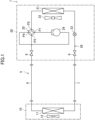
FIG. 1 is a piping system diagram of an air conditioner according to an embodiment. -
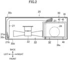
FIG. 2 is a plan sectional view of a configuration of an outdoor unit. -
FIG. 3 is a front sectional view of the configuration of the outdoor unit. -
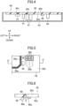
FIG. 4 is a longitudinal sectional view of a configuration of an electric component unit. -
FIG. 5 is a partially enlarged view of a substrate as viewed from a pattern surface. -
FIG. 6 is a side view of a surface mount LED mounted on the substrate. -
FIG. 7 is a side view of two surface mount LEDs mounted on the substrate according to a variation. -
FIG. 8 shows a surface mount LED according to another embodiment mounted on the substrate. - An embodiment of the present disclosure will be described with reference to the drawings. The following embodiment is a merely exemplary one in nature, and is not intended to limit the scope, application, or uses of the invention. Features of the embodiment, variations, and other examples described below can be combined or partially substituted within the range where the present invention can be embodied. In the drawings, the up and down, front and back, and left and right directions are indicated by arrows. Unless otherwise specified, directions such as up and down will be described in accordance with the directions indicated by these arrows.
- As shown in
FIG. 1 , the air conditioner (1) includes a refrigerant circuit (5) that circulates a refrigerant to perform a refrigeration cycle. The air conditioner (1) includes an indoor unit (10) and an outdoor unit (20). The indoor unit (10) is placed inside. The outdoor unit (20) is placed outside. The indoor unit (10) and the outdoor unit (20) are connected to each other by a gas pipe (6) and a liquid pipe (7). The gas pipe (6) is connected with a gas shut-off valve (8). The liquid pipe (7) is connected with a liquid shut-off valve (9). - The indoor unit (10) includes an indoor heat exchanger (11) and an indoor fan (12). The indoor heat exchanger (11) is, for example, a cross-fin type fin-and-tube heat exchanger. In the indoor heat exchanger (11), the refrigerant flowing inside the heat transfer tube and the air blown by the indoor fan (12) exchange heat.
- As shown in
FIGS. 1 to 3 , the outdoor unit (20) includes an outdoor heat exchanger (21), an outdoor fan (22), an outdoor expansion valve (23), a compressor (24), a four-way switching valve (25), and an electric component unit (40). The outdoor heat exchanger (21), the outdoor expansion valve (23), the compressor (24), and the four-way switching valve (25) are connected by a refrigerant pipe (26). - The outdoor heat exchanger (21) is, for example, a cross-fin type fin-and-tube heat exchanger. The outdoor heat exchanger (21) includes a plurality of fins (21a) and a heat transfer tube (21b). The plurality of fins (21a) are spaced in the direction orthogonal to the air flow direction. The heat transfer tube (21b) extends through the fins (21a) in the thickness direction. The heat transfer tube (21b) is disposed through multiple layers in the up-down direction.
- In the outdoor heat exchanger (21), the refrigerant flowing inside the heat transfer tube (21b) and the air blown by the outdoor fan (22) exchange heat. The outdoor expansion valve (23) is, for example, an electronic expansion valve.
- The compressor (24) is, for example, a rotary compressor such as a scroll compressor. The four-way switching valve (25) switches between a cooling operation and a heating operation. In the cooling operation, a first port (P1) and a second port (P2) of the four-way switching valve (25) communicate with each other, and a third port (P3) and a fourth port (P4) communicate with each other (the state indicated by the solid lines in
FIG. 1 ). In the heating operation, the first port (P1) and the third port (P3) of the four-way switching valve (25) communicate with each other, and the second port (P2) and the fourth port (P4) communicate with each other (the state indicated by the broken lines inFIG. 1 ). - The outdoor unit (20) includes a casing (30). The casing (30) includes a body casing (30a) and a top panel (30b). The body casing (30a) is formed in a box shape where its upper surface is open. In other words, the upper surface of the body casing (30a) has an opening (35). The top panel (30b) is attached to the body casing (30a) so as to close the opening (35) of the main casing (30a). The top panel (30b) can be attached to and detached from the body casing (30a). The opening (35) of the body casing (30a) is an example of the opening (35) for maintenance of the outdoor unit (20).
- In the body casing (30a), a partitioning member (31) extending in the front-back direction and the up-down direction is disposed. The partitioning member (31) partitions the inside of the body casing (30a) into a machine chamber (32) and a fan chamber (33).
- In the body casing (30a), the machine chamber (32) is a space located to the right of the partitioning member (31). The compressor (24), the four-way switching valve (25), the refrigerant pipe (26), and the electric component unit (40) are disposed in the machine chamber (32).
- In the body casing (30a), the fan chamber (33) is a space located to the left of the partitioning member (31). The outdoor fan (22) and the outdoor heat exchanger (21) are disposed in the fan chamber (33).
- The body casing (30a) includes a back sidewall and a left sidewall, each of which is provided with a suction port (30c) communicating with the fan chamber (33). When the outdoor fan (22) is driven, outside air is sucked into the fan chamber (33) through the suction port (30c). The body casing (30a) includes a front sidewall which is provided with an outlet port (30d) communicating with the fan chamber (33). When the outdoor fan (22) is driven, air in the fan chamber (33) is blown out through the outlet port (30d).
- The electric component unit (40) serves as a power converter for supplying power to the motor of the compressor (24). As shown in
FIGS. 2 to 4 , the electric component unit (40) includes a substrate casing (43), predetermined electric components (41), a substrate (42), and a surface mount LED (46). The electric component unit (40) is disposed near the top panel (30b) above the machine chamber (32). - The substrate casing (43) is a box-shaped member having an opening at its top. The substrate casing (43) houses various electric components (41) including the substrate (42). Only one substrate (42) is disposed in the substrate casing (43) of this embodiment. The opening at the top of the substrate casing (43) faces the lower surface of the top panel (30b).
- The electric components (41) are mounted on the substrate (42). The electric components (41) are control circuit components such as power transistors, microcomputer chips for controlling devices, or a memory for storing control programs.
- A heat sink (not shown) is provided as a member for reducing temperature increases of the electric components (41) such as power transistors that generate a relatively large amount of heat. The heat sink consists of a metal member.
- As shown in
FIG. 4 , the substrate (42) includes a mounting surface (42a) and a pattern surface (42b). The mounting surface (42a) is an example of the first surface (42a). The pattern surface (42b) is an example of the second surface (42b). The substrate (42) is disposed so that the pattern surface (42b) faces the opening (35) of the body casing (30a). In other words, the substrate (42) is disposed so that the pattern surface (42b) faces upward and the mounting surface (42a) faces downward. The substrate (42) of this embodiment is a single layer. - The electric component (41) and the surface mount LED (46) are disposed on the mounting surface (42a). The details of the surface mount LED (46) will be described later. Various connectors (44) are also mounted on the mounting surface (42a). The connectors (44) are used for, for example, connecting an output (AC power) of an inverter circuit (not shown) to a load (motor).
- The substrate (42) has a plurality of through holes (hereinafter referred to as through holes (42c)). The through holes (42c) are formed for the purpose of, for example, conducting electricity between the mounting surface (42a) and the pattern surface (42b). Terminals of the electric component (41) are soldered on wiring patterns of the substrate (42).
- As shown in
FIG. 5 , the wiring patterns (50a) are formed on the pattern surface (42b). Various electric components (41) are electrically connected to the wiring patterns (50a), thereby forming a predetermined circuit. Silk (50b) is applied onto the pattern surface (42b). The silk (50b) is a coating material for labeling the pattern surface (42b) with predetermined information such as a part number, a manufacturer logo, and a manufacture date. The wiring pattern (50a) and the silk (50b) are examples of the light transmission reduction material (50a, 50b). The light transmission reduction material (50a, 50b) reduces light transmission between the mounting surface (42a) and the pattern surface (42b). - As shown in
FIGS. 5 and 6 , the substrate (42) includes a light transmitting region (60). The light transmitting region (60) is a region in which when the pattern surface (42b) is viewed from front, light is transmitted from the mounting surface (42a) to the pattern surface (42b). In other words, the light transmitting region (60) is a region in which a pattern wire or a silk as the light transmission reduction material (50a, 50b) is not provided. - The surface mount LED (46) is a light source for informing a service person about a microcomputer operation, a communication state, an error state, or the like of the substrate (42). The surface mount LED (46) is a chip LED provided on the mounting surface (42a). In this embodiment, when the air conditioner (1) is operating normally, the surface mount LED (46) is blinking. The surface mount LED (46) is an example of the first light source (46).
- As shown in
FIG. 6 , the surface mount LED (46) of this embodiment is a side emitting chip LED. Specifically, the surface mount LED (46) includes a light emitter (46a) and a light emitting substrate (46b). - The light emitter (46a) is a member that emits light of an LED. Specifically, the light emitter (46a) includes an LED element and an encapsulating resin. The LED element is encapsulated in the encapsulating resin. The encapsulating resin is a transparent or translucent resin (silicone, epoxy resin, or the like). The encapsulating resin is formed in a substantially rectangular parallelepiped shape. The light emitting substrate (46b) controls light emission of the LED element of the light emitter (46a). The light emitting substrate (46b) is attached on the mounting surface (42a).
- The light emitter (46a) is adjacent to the light emitting substrate (46b) in the direction along the mounting surface (42a). Accordingly, as indicated by the arrows in
FIG. 6 , the light emitter (46a) emits light toward the mounting surface (42a) and also emits light in the direction along the mounting surface (42a). - The light emitter (46a) is disposed not to overlap the wiring pattern (50a) or the silk (50b) when the pattern surface (42b) is viewed from front. In other words, the surface mount LED (46) emits light toward the light transmitting region (60). Accordingly, part of LED light emitted from the light emitter (46a) is transmitted from the mounting surface (42a) toward the pattern surface (42b), and the light of the surface mount LED is visible when viewed from the pattern surface.
- In the outdoor unit (20) of this embodiment, the substrate (42) includes the light transmitting region (60) in which light is transmitted from the mounting surface (42a) (the first surface) toward the pattern surface (42b) (the second surface) when the pattern surface (42b) (the second surface) is viewed from front. The substrate (42) also includes the surface mount LED (46) provided on the mounting surface (42a) and configured to emit light toward the light transmitting region (60).
- According to this embodiment, the surface mount LED is mounted as the light source on the mounting surface (42a), and thus the design of the substrate (42) is more flexible than if a lead LED is mounted. Specifically, a lead LED requires two leads connected to the LED and also soldered to the pattern surface (42b) via the through holes (42b). Then, a slit (recess) is formed on part of the mounting surface (42a) that faces the LED (specifically, a position between the two leads) to enable LED light to transmit more easily, so that the substrate (42) is locally thinner. If a lead LED is used as a light source in this manner, the available areas of the mounting surface (42a) and the pattern surface (42b) are smaller, and the design is less flexible. However, if the surface mount LED (46) is used, soldering on the pattern surface (42b) can be omitted, and also no slit needs to be provided and thus the surface of the substrate (42) can be used more effectively.
- In addition, since the light of the surface mount LED (46) emitted to the light transmitting region (60) is transmitted through the substrate (42) in the thickness direction, the light of the surface mount LED (46) is visible when viewed from the pattern surface (42b). Accordingly, the state of light of the surface mount LED (46) can be checked by simply opening the top panel (30b) of the outdoor unit (20). As a result, a service person can easily check a microcomputer operation, a communication state, or an error state of the substrate (42).
- In the outdoor unit (20) of this embodiment, the light transmitting region (60) is a region in which the wiring pattern (50a) and the silk (50b) (the light transmission reduction material) that reduce light transmission between the mounting surface (42a) and the pattern surface (42b) are not provided.
- According to this embodiment, in the light transmitting region (60), the wiring pattern (50a) and the silk are not provided. Thus, when light of the surface mount LED (46) is emitted to that region, light is visible from the pattern surface (42b).
- In the outdoor unit (20) of this embodiment, the surface mount LED (46) is a side emitting chip LED. The light emitted from the light emitter (46a) of the side emitting LED toward the mounting surface (42a) can be transmitted through the substrate (42) in the thickness direction. In addition, the LEDs of the outdoor unit (20) can consist of only the side emitting chip LEDs. Thus, it is unnecessary to use different types of LEDs particularly for the LEDs provided on the substrate (42), and the manufacturing costs and the complex management of the components can be reduced.
- Variations of the outdoor unit (20) of the present disclosure will be described. Configurations different from those of the embodiment will be described.
- As shown in
FIG. 7 , two surface mount LEDs (46, 47) are mounted on the mounting surface (42a) of the substrate (42) of this example. One of the surface mount LEDs is referred to as a first surface mount LED (46), and the other one of the surface mount LEDs is referred to as a second surface mount LED (47). The first surface mount LED (46) and the second surface mount LED (47) are spaced apart from each other at a predetermined distance. The first surface mount LED (46) is an example of the first light source (46). The second surface mount LED (47) is an example of the second light source (47). The first surface mount LED (46) and the second surface mount LED (47) have the same configuration as those of the side emitting LED of the embodiment. The second surface mount LED (47) includes a light emitter (47a) and a light emitting substrate (47b). - The first surface mount LED (46) is a light source for informing a service person about a microcomputer operation, a communication state, an error state, or the like of the substrate (42). The second surface mount LED (47) is a light source for an operator to check the quality of the substrate (42) in the manufacturing process of the substrate (42), for example. That is, the second surface mount LED (47) is a light source that a service person does not need to check.
- The substrate (42) of this example includes a light transmission reduction material (50a, 50b) that reduces transmission of light toward the mounting surface (42a) of the second surface mount LED (47). Specifically, the light transmission reduction material is a silk (50b) applied onto the pattern surface (42b). The silk (50b) is applied to part of the pattern surface (42b) on which the second surface mount LED (47) is disposed.
- Accordingly, even if the second surface mount LED (47) emits light, the silk (50b) reduces transmission of light toward the mounting surface (42a) through the substrate (42) (see the arrow in
FIG. 7 ). Accordingly, a service person can visually check the first surface mount LED (46) only, and does not mistake the light of the first surface mount LED (46) for the light of the second surface mount LED (47). - The above embodiment and variations may be configured as follows.
- As shown in
FIG. 8 , the surface mount LED (46) may be a back emitting chip LED. In the back emitting LED, the light emitter (46a) is disposed between the light emitting substrate (46b) and the mounting surface (42a). The light emitting substrate (46b) is conductively connected to the substrate (42). The light emitter (46a) emits light toward the mounting surface (42a) and along the mounting surface (42a) (see the arrows inFIG. 8 ). Part of the light toward the mounting surface (42a) passes through the light transmitting region. That is, even the back emitting chip LED enables light transmitted through the substrate (42) to be visible from the pattern surface (42b). - The substrate (42) may be comprised of a plurality of substrates (42). In this case, the light transmitting region (60) is a region in which light is transmitted through layers. In other words, the light transmitting region (60) is a region in which the wiring pattern (50a) and the silk (50b) are not provided in each layer. Thus, even the multilayer substrate (42), where the surface mount LED (46) is disposed on part of the mounting surface (42a) that corresponds to the light transmitting region (60), enables LED light to be visible from the back surface (pattern surface (42b)) of the mounting surface (42a).
- In the variation, the light transmission reduction material (50a, 50b) may be the wiring pattern (50a). Specifically, the second surface mount LED (47) may be disposed on the back surface (mounting surface (42a)) of the wiring pattern (50a). Accordingly, light from the second surface mount LED (47) toward the substrate (42) is less transmitted through the substrate (42) by the wiring pattern (50a).
- While the embodiment and variations thereof have been described above, it will be understood that various changes in form and details may be made without departing from the spirit and scope of the claims. The embodiment and the variations thereof may be combined and replaced with each other without deteriorating intended functions of the present disclosure. The expressions of "first," "second," . . . described above are used to distinguish the terms to which these expressions are given, and do not limit the number and order of the terms.
- As described above, the present disclosure is useful for an outdoor unit.
-
- 1
- Air Conditioner
- 20
- Outdoor Unit
- 30
- Casing
- 35
- Opening
- 41
- Electric Component
- 42
- Substrate
- 42a
- Mounting Surface (First Surface)
- 42b
- Pattern Surface (Second Surface)
- 46
- Surface Mount LED, First Surface Mount LED (First Light Source)
- 46a
- Light Emitter
- 46b
- Light Emitting Substrate
- 47
- Second Surface Mount LED (Second Light Source)
- 50a, 50b
- Light Transmission Reduction Material
- 60
- Light Transmitting Region
Claims (5)
- An outdoor unit of an air conditioner (1), comprising:a casing (30) having an opening (35) for maintenance; anda substrate (42) disposed in the casing (30) and including a first surface (42a) on which an electric component (41) is disposed and a second surface (42b) facing the opening (35),whereinthe substrate (42) includesa light transmitting region (60) in which light is transmitted from the first surface (42a) toward the second surface (42b) when the second surface (42b) is viewed from front, anda first light source (46) provided on the first surface (42a), andthe first light source (46) is a surface mount LED that emits light toward the light transmitting region (60).
- The outdoor unit of claim 1, wherein
the light transmitting region (60) is a region in which a light transmission reduction material (50a, 50b) that reduces light transmission between the first surface (42a) and the second surface (42b) is not provided. - The outdoor unit of claim 1 or 2, wherein
the first light source (46) includesa light emitter (46a) including an LED element, anda light emitting substrate (46b) provided on the first surface (42a) and configured to control light emission of the LED element, andthe light emitter (46a) is adjacent to the light emitting substrate (46b) in a direction along the first surface (42a). - The outdoor unit of claim 1 or 2, whereinthe first light source (46) includesa light emitter (46a) including an LED element, anda light emitting substrate (46b) provided on the first surface (42a) and configured to control light emission of the LED element, andthe light emitter (46a) is disposed between the first surface (42a) and the light emitting substrate (46b).
- The outdoor unit of any one of claims 1 to 4, further comprising:a second light source (47) disposed on the first surface (42a) at a predetermined distance from the first light source (46) and configured to emit light toward the first surface (42a); anda light transmission reduction material (50a, 50b) that reduces light transmission between the first surface (42a) and the second surface (42b),whereinthe light transmission reduction material (50a, 50b) reduces transmission of light between the first surface (42a) and the second surface (42b), where the light is emitted from the second light source (47).
Applications Claiming Priority (2)
| Application Number | Priority Date | Filing Date | Title |
|---|---|---|---|
| JP2022110730A JP7864026B2 (en) | 2022-07-08 | 2022-07-08 | Outdoor unit |
| PCT/JP2023/017063 WO2024009597A1 (en) | 2022-07-08 | 2023-05-01 | Outdoor unit |
Publications (2)
| Publication Number | Publication Date |
|---|---|
| EP4538604A1 true EP4538604A1 (en) | 2025-04-16 |
| EP4538604A4 EP4538604A4 (en) | 2025-09-17 |
Family
ID=89453019
Family Applications (1)
| Application Number | Title | Priority Date | Filing Date |
|---|---|---|---|
| EP23835138.1A Pending EP4538604A4 (en) | 2022-07-08 | 2023-05-01 | Outdoor unit |
Country Status (5)
| Country | Link |
|---|---|
| US (1) | US20250146682A1 (en) |
| EP (1) | EP4538604A4 (en) |
| JP (1) | JP7864026B2 (en) |
| CN (1) | CN119497807A (en) |
| WO (1) | WO2024009597A1 (en) |
Family Cites Families (5)
| Publication number | Priority date | Publication date | Assignee | Title |
|---|---|---|---|---|
| JPH1123010A (en) * | 1997-07-08 | 1999-01-26 | Funai Electric Co Ltd | Outdoor unit abnormality check device in air conditioner |
| JP2002228199A (en) | 2001-01-29 | 2002-08-14 | Daikin Ind Ltd | Circuit boards and air conditioners |
| JP2005195209A (en) | 2004-01-05 | 2005-07-21 | Daikin Ind Ltd | Outdoor unit failure diagnosis apparatus, outdoor unit electrical component unit, and outdoor unit including the same |
| JP2015119010A (en) * | 2013-12-17 | 2015-06-25 | オリンパス株式会社 | Illumination device and photographing device |
| JP7796656B2 (en) * | 2020-09-08 | 2026-01-09 | 三菱電機株式会社 | outdoor unit |
-
2022
- 2022-07-08 JP JP2022110730A patent/JP7864026B2/en active Active
-
2023
- 2023-05-01 WO PCT/JP2023/017063 patent/WO2024009597A1/en not_active Ceased
- 2023-05-01 EP EP23835138.1A patent/EP4538604A4/en active Pending
- 2023-05-01 CN CN202380051351.2A patent/CN119497807A/en active Pending
-
2025
- 2025-01-07 US US19/012,301 patent/US20250146682A1/en active Pending
Also Published As
| Publication number | Publication date |
|---|---|
| EP4538604A4 (en) | 2025-09-17 |
| JP2024008675A (en) | 2024-01-19 |
| CN119497807A (en) | 2025-02-21 |
| WO2024009597A1 (en) | 2024-01-11 |
| US20250146682A1 (en) | 2025-05-08 |
| JP7864026B2 (en) | 2026-05-22 |
Similar Documents
| Publication | Publication Date | Title |
|---|---|---|
| US20130163248A1 (en) | Led-based light engine | |
| US9693490B2 (en) | Refrigeration device | |
| EP1406303A1 (en) | Power module and air conditioner | |
| JP5606381B2 (en) | Lighting device | |
| CN101873762A (en) | A printed circuit board | |
| EP3847395B1 (en) | Lighting device comprising circuit board | |
| US20140268827A1 (en) | Cooling System and LED- Based Light Comprising Same | |
| CN214223263U (en) | Air conditioner driving heat dissipation structure and air conditioner thereof | |
| WO2001016532A1 (en) | Air conditioner | |
| CN105674643B (en) | refrigeration unit | |
| US20250146682A1 (en) | Outdoor unit | |
| JP6703877B2 (en) | Air conditioner | |
| CN104620485A (en) | Inverter device for air conditioner | |
| CN104121640A (en) | Transversely-blowing type air conditioner outdoor unit | |
| JP4991467B2 (en) | Circuit module and outdoor unit using the same | |
| KR100412150B1 (en) | Air conditioner | |
| CN102313186A (en) | Indoor illumination device | |
| WO2020208670A1 (en) | Outdoor unit for air-conditioner | |
| CN100557798C (en) | Power module, method of manufacturing the same, and air conditioner | |
| JP4269603B2 (en) | Outdoor unit electrical component unit | |
| CN117121186A (en) | Electrical installation parts and refrigeration equipment | |
| JP7580654B2 (en) | Drive unit and air conditioning device | |
| JP7746894B2 (en) | Electrical equipment boxes and outdoor units of air conditioners | |
| CN223258344U (en) | Electric control part and air conditioner with same | |
| JP2002228197A (en) | Circuit boards and air conditioners |
Legal Events
| Date | Code | Title | Description |
|---|---|---|---|
| STAA | Information on the status of an ep patent application or granted ep patent |
Free format text: STATUS: THE INTERNATIONAL PUBLICATION HAS BEEN MADE |
|
| PUAI | Public reference made under article 153(3) epc to a published international application that has entered the european phase |
Free format text: ORIGINAL CODE: 0009012 |
|
| STAA | Information on the status of an ep patent application or granted ep patent |
Free format text: STATUS: REQUEST FOR EXAMINATION WAS MADE |
|
| 17P | Request for examination filed |
Effective date: 20250108 |
|
| AK | Designated contracting states |
Kind code of ref document: A1 Designated state(s): AL AT BE BG CH CY CZ DE DK EE ES FI FR GB GR HR HU IE IS IT LI LT LU LV MC ME MK MT NL NO PL PT RO RS SE SI SK SM TR |
|
| A4 | Supplementary search report drawn up and despatched |
Effective date: 20250814 |
|
| RIC1 | Information provided on ipc code assigned before grant |
Ipc: F24F 1/20 20110101AFI20250808BHEP Ipc: F21V 19/00 20060101ALI20250808BHEP Ipc: F21V 23/00 20150101ALI20250808BHEP Ipc: H05K 1/02 20060101ALI20250808BHEP Ipc: H05K 1/18 20060101ALI20250808BHEP Ipc: F21Y 115/10 20160101ALI20250808BHEP Ipc: F24F 1/56 20110101ALI20250808BHEP Ipc: F21V 33/00 20060101ALI20250808BHEP |
|
| P01 | Opt-out of the competence of the unified patent court (upc) registered |
Free format text: CASE NUMBER: UPC_APP_3797_4538604/2025 Effective date: 20250820 |
|
| DAV | Request for validation of the european patent (deleted) | ||
| DAX | Request for extension of the european patent (deleted) | ||
| REG | Reference to a national code |
Ref country code: DE Ref legal event code: R079 Free format text: PREVIOUS MAIN CLASS: F24F0001200000 Ipc: H05K0001020000 |
|
| GRAP | Despatch of communication of intention to grant a patent |
Free format text: ORIGINAL CODE: EPIDOSNIGR1 |
|
| STAA | Information on the status of an ep patent application or granted ep patent |
Free format text: STATUS: GRANT OF PATENT IS INTENDED |
|
| RIC1 | Information provided on ipc code assigned before grant |
Ipc: H05K 1/02 20060101AFI20260702BHEP Ipc: H05K 1/18 20060101ALI20260702BHEP Ipc: F21V 23/00 20150101ALI20260702BHEP Ipc: F24F 11/38 20180101ALI20260702BHEP Ipc: F24F 1/20 20110101ALI20260702BHEP Ipc: F21V 19/00 20060101ALI20260702BHEP Ipc: F21V 33/00 20060101ALI20260702BHEP Ipc: F24F 1/56 20110101ALI20260702BHEP Ipc: F24F 11/52 20180101ALI20260702BHEP Ipc: H05K 1/181 20260101ALI20260702BHEP |