EP4538588A1 - Led filament arrangement - Google Patents
Led filament arrangement Download PDFInfo
- Publication number
- EP4538588A1 EP4538588A1 EP24221558.0A EP24221558A EP4538588A1 EP 4538588 A1 EP4538588 A1 EP 4538588A1 EP 24221558 A EP24221558 A EP 24221558A EP 4538588 A1 EP4538588 A1 EP 4538588A1
- Authority
- EP
- European Patent Office
- Prior art keywords
- led
- led filament
- filaments
- elements
- light
- Prior art date
- Legal status (The legal status is an assumption and is not a legal conclusion. Google has not performed a legal analysis and makes no representation as to the accuracy of the status listed.)
- Granted
Links
Images

Classifications
-
- F—MECHANICAL ENGINEERING; LIGHTING; HEATING; WEAPONS; BLASTING
- F21—LIGHTING
- F21K—NON-ELECTRIC LIGHT SOURCES USING LUMINESCENCE; LIGHT SOURCES USING ELECTROCHEMILUMINESCENCE; LIGHT SOURCES USING CHARGES OF COMBUSTIBLE MATERIAL; LIGHT SOURCES USING SEMICONDUCTOR DEVICES AS LIGHT-GENERATING ELEMENTS; LIGHT SOURCES NOT OTHERWISE PROVIDED FOR
- F21K9/00—Light sources using semiconductor devices as light-generating elements, e.g. using light-emitting diodes [LED] or lasers
- F21K9/20—Light sources comprising attachment means
- F21K9/23—Retrofit light sources for lighting devices with a single fitting for each light source, e.g. for substitution of incandescent lamps with bayonet or threaded fittings
- F21K9/232—Retrofit light sources for lighting devices with a single fitting for each light source, e.g. for substitution of incandescent lamps with bayonet or threaded fittings specially adapted for generating an essentially omnidirectional light distribution, e.g. with a glass bulb
-
- F—MECHANICAL ENGINEERING; LIGHTING; HEATING; WEAPONS; BLASTING
- F21—LIGHTING
- F21S—NON-PORTABLE LIGHTING DEVICES; SYSTEMS THEREOF; VEHICLE LIGHTING DEVICES SPECIALLY ADAPTED FOR VEHICLE EXTERIORS
- F21S8/00—Lighting devices intended for fixed installation
- F21S8/04—Lighting devices intended for fixed installation intended only for mounting on a ceiling or the like overhead structures
- F21S8/06—Lighting devices intended for fixed installation intended only for mounting on a ceiling or the like overhead structures by suspension
-
- F—MECHANICAL ENGINEERING; LIGHTING; HEATING; WEAPONS; BLASTING
- F21—LIGHTING
- F21V—FUNCTIONAL FEATURES OR DETAILS OF LIGHTING DEVICES OR SYSTEMS THEREOF; STRUCTURAL COMBINATIONS OF LIGHTING DEVICES WITH OTHER ARTICLES, NOT OTHERWISE PROVIDED FOR
- F21V19/00—Fastening of light sources or lamp holders
- F21V19/001—Fastening of light sources or lamp holders the light sources being semiconductors devices, e.g. LEDs
- F21V19/003—Fastening of light source holders, e.g. of circuit boards or substrates holding light sources
-
- F—MECHANICAL ENGINEERING; LIGHTING; HEATING; WEAPONS; BLASTING
- F21—LIGHTING
- F21V—FUNCTIONAL FEATURES OR DETAILS OF LIGHTING DEVICES OR SYSTEMS THEREOF; STRUCTURAL COMBINATIONS OF LIGHTING DEVICES WITH OTHER ARTICLES, NOT OTHERWISE PROVIDED FOR
- F21V23/00—Arrangement of electric circuit elements in or on lighting devices
- F21V23/003—Arrangement of electric circuit elements in or on lighting devices the elements being electronics drivers or controllers for operating the light source, e.g. for a LED array
-
- F—MECHANICAL ENGINEERING; LIGHTING; HEATING; WEAPONS; BLASTING
- F21—LIGHTING
- F21V—FUNCTIONAL FEATURES OR DETAILS OF LIGHTING DEVICES OR SYSTEMS THEREOF; STRUCTURAL COMBINATIONS OF LIGHTING DEVICES WITH OTHER ARTICLES, NOT OTHERWISE PROVIDED FOR
- F21V3/00—Globes; Bowls; Cover glasses
- F21V3/02—Globes; Bowls; Cover glasses characterised by the shape
-
- F—MECHANICAL ENGINEERING; LIGHTING; HEATING; WEAPONS; BLASTING
- F21—LIGHTING
- F21Y—INDEXING SCHEME ASSOCIATED WITH SUBCLASSES F21K, F21L, F21S and F21V, RELATING TO THE FORM OR THE KIND OF THE LIGHT SOURCES OR OF THE COLOUR OF THE LIGHT EMITTED
- F21Y2103/00—Elongate light sources, e.g. fluorescent tubes
- F21Y2103/10—Elongate light sources, e.g. fluorescent tubes comprising a linear array of point-like light-generating elements
-
- F—MECHANICAL ENGINEERING; LIGHTING; HEATING; WEAPONS; BLASTING
- F21—LIGHTING
- F21Y—INDEXING SCHEME ASSOCIATED WITH SUBCLASSES F21K, F21L, F21S and F21V, RELATING TO THE FORM OR THE KIND OF THE LIGHT SOURCES OR OF THE COLOUR OF THE LIGHT EMITTED
- F21Y2115/00—Light-generating elements of semiconductor light sources
- F21Y2115/10—Light-emitting diodes [LED]
-
- H—ELECTRICITY
- H10—SEMICONDUCTOR DEVICES; ELECTRIC SOLID-STATE DEVICES NOT OTHERWISE PROVIDED FOR
- H10W—GENERIC PACKAGES, INTERCONNECTIONS, CONNECTORS OR OTHER CONSTRUCTIONAL DETAILS OF DEVICES COVERED BY CLASS H10
- H10W90/00—Package configurations
Definitions
- the plurality of LED filaments of the LED filament arrangement may be arranged in many different configurations with respect to each other, while at the same time avoiding the arrangement of being (substantially) parallel, thereby contributing to the dynamic shadowing effect.
- the LEDs are arranged on an elongated carrier or a substrate, like for instance a carrier that may be rigid (made from e.g. a polymer, glass, quartz, metal or sapphire) or flexible (e.g. made of a polymer or metal e.g. a film or foil of poly imide).
- a carrier may be rigid (made from e.g. a polymer, glass, quartz, metal or sapphire) or flexible (e.g. made of a polymer or metal e.g. a film or foil of poly imide).
- the carrier comprises a first major surface and an opposite second major surface
- the LEDs are arranged on at least one of these surfaces, e.g. on both of the first and second major surfaces.
- the carrier may be reflective or light transmissive, such as translucent and preferably transparent.
- the LED filament may comprise an encapsulant at least partly covering at least part of the plurality of LEDs.
- the frame it is here meant a structure, support, construction, or the like, which may have the shape of a grid or mesh.
- the frame comprises a plurality of first elements of elongated shape defining a mesh structure of the frame, wherein the plurality of first elements comprises a material being at least partially opaque.
- the plurality of first elements may comprise a material which is partially, or totally, opaque or non-transparent. It will be appreciated that the first elements may be construed as “blocking elements” and/or “blocking portions" of the frame.
- At least one first element of the plurality of first elements elongates along a respective first element axis, C i , wherein a respective first angle, ⁇ i , between A i and C i , and wherein a respective second angle, ⁇ i , between B i and C i fulfils
- the first angle(s) ⁇ i between the at least one first LED filament and the at least one first element of the frame, and the second angle(s) ⁇ i between the at least one second LED filament and the at least one first element differ from each other in their absolute values.
- the first and second LED filaments may be arranged at different angles with respect to one or more first elements of the plurality of first elements.
- the LED filament arrangement further comprises a control unit configured to individually control the operation of the at least one first LED filament at the at least one second LED filament of the plurality of LED filaments.
- operation it is hereby meant e.g. an on/off operation, an increasing and/or decreasing of the light intensity, variation of the color of the light emitted from the LEDs of the plurality of LED filaments.
- the control unit may be configured to control the operation of the first and second LED filaments such that the first LED filament(s) is (are) arranged to emit a first light output and the second LED filament(s) is (are) arranged to emit second light output.
- the present embodiment is advantageous in that the LED filament arrangement is hereby able to produce decorative (white) light while at the same time being able to induce improved and/or new dynamic shadows.
- the at least one first LED filament, the at least one second LED filament and the at least one third LED filament may be arranged at an angle, ⁇ i in the range of 30-60° with respect to each other.
- the plurality of LED filaments of the LED filament arrangement may be arranged in many different configurations with respect to each other, while at the same time avoiding the arrangement of being (substantially) parallel.
- the arrangement of the plurality of LED filaments in the LED filament arrangement may be symmetric, which may even further contribute to the aesthetical appearance of the LED filament arrangement and/or the light emitted therefrom during operation.
- the present embodiment is advantageous in that this wide range of choice of the arrangements of the LED filaments with respect to each other may result in an even more decorative lighting and/or dynamic shadowing during operation.
- the frame may comprise at least 3, preferably at least 5, and even more preferred 10 first elements which are arranged substantially perpendicular to at least one LED filament of the plurality of LED filaments.
- the respective first angle, ⁇ i between the respective first axis A i of the at least one first LED filament and the respective first element axis, C i , of the plurality of first elements may be 90°, or close to 90°.
- the relationship between the width, Wi, of the plurality of first elements and the width, W 2 , of the plurality of LED filaments may be 2W 2 ⁇ W 1 ⁇ 20W 2 , preferably 3W 2 ⁇ W 1 ⁇ 15W 2 , and even more preferred 4W 2 ⁇ W 1 ⁇ 10W 2 .
- the relationship between the width, Wi, of the plurality of first elements and the length, L 2 , of the plurality of LED filaments may be 2Wi ⁇ L 2 , preferably 2.5W 1 ⁇ L 2 , and even more preferred 3Wi ⁇ L 2 .
- the control unit may comprise a random current generator configured to supply current which varies randomly, to the plurality of LEDs.
- random current generator it is here meant substantially any generator, unit, or the like, which is configured to generate and supply a current which randomly varies in amplitude with time.
- the present embodiment is advantageous in that the randomly generated current(s) of the random current generator may contribute to obtaining a resemblance of candle light by the light emitted from the LEDs. Consequently, this effect may even further contribute to the decorative aspect of the LED filament arrangement.
- Fig. 2a schematically shows a side view of a portion of a LED filament arrangement 100 according to an embodiment of the present invention.
- a single (first) LED filament 110a and a single first element 210 of the LED filament arrangement 100 are shown.
- the elongated LED filament 110a elongates along a first axis, A i
- the elongated first element 210 elongates along a respective first element axis, C i , wherein these axes, according to this example, are parallel to a main axis, A.
- a first angle, ⁇ i between A i and C i , is 0° in this example.
- the first element 210 forms part of a frame at least partially enclosing a plurality of LED filaments (of which only a single LED filament 110a is shown) of the LED filament arrangement 100.
- the frame of the LED filament arrangement 100 comprises a plurality of first elements 210, only a single first element 210 is disclosed for reasons of simplicity.
- the first element 210 has an elongated shape, such as a rod shape, and comprises a material which is at least partially opaque.
- the first element 210 is (completely) light blocking, wherein its reflective or absorption properties is > 99%.
- the first element 210 may be white or black or metallic.
- the first element 210 may be hollow, and may comprise air.
- Fig. 2b schematically shows a top view of a portion of a LED filament arrangement 100 according to an embodiment of the present invention. It should be noted that Fig. 2b corresponds to Fig. 2a , as Fig. 2b merely shows Fig. 2a from another view as indicated by the axis A. Due to this, it is referred to Fig. 2a for a more detailed understanding of the properties and/or embodiments of the LED filament arrangement 100. As illustrated by Fig.
- the length, L 2 , of the LED filament 110b and the width, Wi, of the first element 210 as well as the distance, D, between the LED filament 110a and the first element 210 in a direction perpendicular to the axis A influence the shadow properties of the light emitted from the lighting device 100 during operation. This is indicated by the schematically illustrated light rays 111a, 111b emitted from the LED filament 110a during operation, resulting in illuminated portions of space 112a, 112c and the portion of space 112b being in shadow immediately behind the first element 210.
- first and second LED filaments 110a, 110b may alternatively be arranged at an angle ⁇ i in the range of 60-90°, preferably in the range of 70-90°, and even more preferred in the range of 80-90° with respect to each other.
- first element 210 elongates along the first element axis, C i , which, according to this example, is parallel to A i and parallel to the main axis, A.
- a first angle, ⁇ i between A i and C i , is 0° in this example.
- the frame may comprise at least three, preferably at least five, and even more preferred ten first elements 210 for each LED filament of the LED filament arrangement 100.
- the first elements 210 are exemplified as being arranged symmetrically around the first LED filament 110a, but it should be noted that the first elements 210 alternatively may be arranged asymmetrically with respect to the first LED filament 110a.
- the schematically illustrated light rays 111a, 111b emitted from the LED filament 110a during operation respectively results in illuminated portions of space 112a, 112c, wherein the portion of space 112b is in shadow behind the first element 210.
- a plurality of second elements 220 of the LED filament arrangement 100 is arranged between the plurality of first elements 210.
- the second elements 220 are exemplified as being plate-shaped, but it should be noted that the second elements 220 may have substantially any shape.
- the second elements 220 comprise a material being at least partially light-transmissive, such that the second elements 220 constitute optically transmissive portions of the frame 200.
- the frame 200 constituted by the arrangement of the plurality of first and second elements 210, 220 has a faceted structure or configuration.
- the distance between the two LED filaments 110a, 110b and the frame 200 is preferably in the range from 1 cm to 100 cm, more preferably 3 cm to 60 cm, and even more preferred 10 to 50 cm.
Landscapes
- Engineering & Computer Science (AREA)
- General Engineering & Computer Science (AREA)
- Microelectronics & Electronic Packaging (AREA)
- Physics & Mathematics (AREA)
- Optics & Photonics (AREA)
- Non-Portable Lighting Devices Or Systems Thereof (AREA)
- Fastening Of Light Sources Or Lamp Holders (AREA)
- Arrangement Of Elements, Cooling, Sealing, Or The Like Of Lighting Devices (AREA)
- Led Device Packages (AREA)
Abstract
Description
- The present invention generally relates to lighting arrangements comprising one or more light emitting diodes (LEDs). More specifically, the present invention is related to a light emitting diode (LED) filament arrangement.
- The use of light emitting diodes (LEDs) for illumination purposes continues to attract attention. Compared to incandescent lamps, fluorescent lamps, neon tube lamps, etc., LEDs provide numerous advantages such as a longer operational life, a reduced power consumption, and an increased efficiency related to the ratio between light energy and heat energy.
- There is currently a very large interest in lighting devices and/or arrangements (such as lamps) provided with LEDs, and incandescent lamps are rapidly being replaced by LED-based lighting solutions. It is nevertheless appreciated and desired to have retrofit lighting devices (e.g. lamps) which have the look of an incandescent bulb. For this purpose, it is possible to make use of the infrastructure for producing incandescent lamps based on LED filaments arranged in such a bulb. In particular, LED filament lamps are highly appreciated as they are very decorative.
- It is of further interest to have lighting devices and/or arrangements (such as lamps) which are able to produce decorative (white) light and induce improved and/or new dynamic shadows. In the prior art, there are lighting devices which are intended to produce decorative light. However, these lighting devices are often unable to provide a dynamic shadowing in a satisfactory manner.
- In
CA 3013021 an omnidirectional LED filament holder and lighting device comprising the same comprises a filament tree supporting a plurality of linear LED filaments having a twisted orientation relative to a central support stalk of the filament tree is disclosed. When arranged within a globe of a lighting device, the omnidirectional LED filament holder provides a lighting device providing omnidirectional light emission usable for general lighting applications while providing a desirable aesthetic for the lighting device. - The invention in
KR101918016 B1 - Hence, it is an object of the present invention to provide alternatives to existing lamps of the prior art in order to obtain a more decorative lighting while at the same time providing a dynamic shadowing.
- Hence, it is of interest to overcome at least some of the deficiencies of present LED filament lamps, in order to improve the distribution of light during operation.
- This and other objects are achieved by providing a LED filament arrangement having the features in the independent claim. Preferred embodiments are defined in the dependent claims.
- Hence, according to the present invention, there is provided a light emitting diode, LED, filament arrangement. The LED filament arrangement comprises a plurality of LED filaments. Each LED filament comprises an array of a plurality of light emitting diodes, LEDs, arranged on an elongated carrier. At least one first LED filament of the plurality of LED filaments elongates along a respective first axis, Ai, and at least one second LED filament of the plurality of LED filaments elongates along a respective second axis, Bi, wherein at least one of a respective angle, θi, between Ai and Bi fulfils |θi| > 10°. The LED filament arrangement further comprises a frame at least partially enclosing the plurality of LED filaments. The frame comprises a plurality of first elements of elongated shape defining a mesh structure of the frame, wherein the plurality of first elements comprises a material being at least partially opaque. At least one first element of the plurality of first elements elongates along a respective first element axis, Ci, wherein a respective first angle, αi, between Ai and Ci, and wherein a respective second angle, βi, between Bi and Ci fulfils |αi| ≠ |βi|. The LED filament arrangement further comprises a control unit configured to individually control the operation of the at least one first LED filament and the at least one second LED filament of the plurality of LED filaments.
- Thus, the present invention is based on the idea of providing a LED filament arrangement which, via its LED filaments comprising LEDs, is able to emit light at least partially through its frame during operation of the LED filaments by the control unit. More specifically, the LED filament arrangement is able to modulate a spatial light distribution of the total light emitted by the LED filament arrangement via its frame comprising a plurality of opaque first elements arranged as a mesh. By this specific arrangement of the first LED filament(s), the second LED filament(s), and the plurality of first elements, wherein the first and second LED filaments form the respective angle |θi| > 10° between each other, the plurality of LED filaments of the LED filament arrangement may be arranged in many different configurations with respect to each other, while at the same time avoiding the arrangement of being (substantially) parallel, thereby contributing to the dynamic shadowing effect. Furthermore, one or more first LED filaments are arranged at a respective first angle, αi, with respect to the first element(s), whereas one or more second LED filaments are arranged at a respective second angle, Di, with respect to the first element(s), which fulfils |αi| ≠ |βi|, i.e. such that the first and second LED filaments are arranged at different angles with respect to the first elements, which also contributes to the dynamic shadowing effect. Hence, the LED filament arrangement is hereby able to produce decorative (white) light while at the same time being able to induce a dynamic shadowing effect.
- It will be appreciated that the LED filament arrangement of the present invention furthermore comprises relatively few components. The relatively low number of components is advantageous in that the LED filament arrangement is relatively inexpensive to fabricate. Moreover, the relatively low number of components of the LED filament arrangement implies an easier recycling, especially compared to devices or arrangements comprising a relatively high number of components which impede an easy disassembling and/or recycling operation.
- There is provided a light emitting diode, LED, filament arrangement. The LED filament arrangement comprises a plurality of LED filaments. A LED filament is providing LED filament light and comprises a plurality of LEDs arranged in a linear array. By the term "array", it is here meant a linear arrangement, row or chain of LEDs, or the like, arranged on the LED filament. Preferably, the LED filament has a length L and a width W, wherein L > 5W. The LED filament may be arranged in a straight configuration or in a non-straight configuration such as for example a curved configuration, a 2D/3D spiral or a helix. Preferably, the LEDs are arranged on an elongated carrier or a substrate, like for instance a carrier that may be rigid (made from e.g. a polymer, glass, quartz, metal or sapphire) or flexible (e.g. made of a polymer or metal e.g. a film or foil of poly imide). In case the carrier comprises a first major surface and an opposite second major surface, the LEDs are arranged on at least one of these surfaces, e.g. on both of the first and second major surfaces. The carrier may be reflective or light transmissive, such as translucent and preferably transparent. The LED filament may comprise an encapsulant at least partly covering at least part of the plurality of LEDs. The encapsulant may also at least partly cover at least one of the first major or second major surface. By the term "encapsulant", it is here meant a material, element, arrangement, or the like, which is configured or arranged to surround, encapsulate and/or enclose the plurality of LEDs of the LED filament(s).
- At least one first LED filament of the plurality of LED filaments elongates along a respective first axis, Ai, and at least one second LED filament of the plurality of LED filaments elongates along a respective second axis, Bi. At least one of a respective angle, θi, between Ai and Bi fulfils |θi | > 10°. In other words, each pair of LED filaments of the plurality of LED filaments may be arranged at a respective angle, θi=1,2,...,n in space with respect to each other, wherein at least one of the angles fulfils |θi| > 10°. The LED filament arrangement further comprises a frame at least partially enclosing the plurality of LED filaments. By the term "frame", it is here meant a structure, support, construction, or the like, which may have the shape of a grid or mesh. The frame comprises a plurality of first elements of elongated shape defining a mesh structure of the frame, wherein the plurality of first elements comprises a material being at least partially opaque. Hence, the plurality of first elements may comprise a material which is partially, or totally, opaque or non-transparent. It will be appreciated that the first elements may be construed as "blocking elements" and/or "blocking portions" of the frame. At least one first element of the plurality of first elements elongates along a respective first element axis, Ci, wherein a respective first angle, αi, between Ai and Ci, and wherein a respective second angle, βi, between Bi and Ci fulfils |αi| ≠ |βi|. Hence, the first angle(s) αi between the at least one first LED filament and the at least one first element of the frame, and the second angle(s) βi between the at least one second LED filament and the at least one first element differ from each other in their absolute values. In other words, the first and second LED filaments may be arranged at different angles with respect to one or more first elements of the plurality of first elements.
- The LED filament arrangement further comprises a control unit configured to individually control the operation of the at least one first LED filament at the at least one second LED filament of the plurality of LED filaments. By the term "operation", it is hereby meant e.g. an on/off operation, an increasing and/or decreasing of the light intensity, variation of the color of the light emitted from the LEDs of the plurality of LED filaments. For example, the control unit may be configured to control the operation of the first and second LED filaments such that the first LED filament(s) is (are) arranged to emit a first light output and the second LED filament(s) is (are) arranged to emit second light output. The present embodiment is advantageous in that the LED filament arrangement is hereby able to produce decorative (white) light while at the same time being able to induce improved and/or new dynamic shadows.
- According to an embodiment of the present invention, the frame may further comprise a plurality of second elements arranged between the first elements, wherein the plurality of second elements comprises a material being at least partially light-transmissive. Preferably, the plurality of second elements is (fully) light transmissive, leading to an even further improved shadowing effect. It will be appreciated that the second elements may be construed as "contrast elements", "contrast producing elements", or the like, of the frame.
- According to an embodiment of the present invention, |αi| < 20° and |βi| > 40°. In other words, the respective first angle, αi, between the at least one first LED filament and the respective first element may be relatively small, whereas the respective second angle, βi, between the at least one second LED filament and the respective first element may be relatively large. The present embodiment is advantageous in that the one or more first LED filaments may be arranged parallel or substantially parallel with the first element(s), or may form (a) relatively small angle(s) with the first element(s), whereas the one or more second LED filaments may be arranged at (a) relatively large angle(s) with the first element(s). This particular arrangement of the first and second LED filaments with respect to the at least partially opaque first elements of the frame may induce an even more dynamic and/or aesthetical shadowing effect.
- According to an embodiment of the present invention, |θi| may be in the range of 60-90°, preferably in the range of 70-90°, and even more preferred in the range of 80-90°. For example, in case of a first and a second LED filament, the two LED filaments may preferably be arranged at an angle, θi in the range of 80-90° with respect to each other. Hence, the first and second LED filament may in this example be arranged (substantially) perpendicular to each other in space. Furthermore, in combination with a relatively small respective first angle αi between a first LED filament(s) and a first element, respectively, the first LED filament(s) may be arranged (substantially) parallel to the first element(s) whereas the second LED filament(s) may be arranged (substantially) perpendicular to the first element(s). The present embodiment is advantageous in that this arrangement of the first and second LED filaments with respect to each other may even further enhance the decorative aspect of the light and the dynamic shadowing thereof during operation of the LED filament arrangement.
- According to an embodiment of the present invention, at least one third LED filament of the plurality of LED filaments may elongate along a respective third axis, Di, wherein at least one of the respective angles, θi, between Ai and Bi, between Ai and Di, and between Bi and Di, respectively, may fulfil |θi| > 10°. Hence, for at least one arbitrary pair of the at least one first, second and third LED filaments, the respective pair of LED filaments may be arranged at an angle, θi, with respect to each other, wherein |θi| > 10°. The present embodiment is advantageous in that this arrangement of the first, second and third LED filaments with respect to each other may result in an even more dynamic shadowing during operation of the LED filament arrangement.
- According to an embodiment of the present invention, |θi| may be in the range of 30-60°. Hence, the at least one first LED filament, the at least one second LED filament and the at least one third LED filament may be arranged at an angle, θi in the range of 30-60° with respect to each other. It will be appreciated that the plurality of LED filaments of the LED filament arrangement may be arranged in many different configurations with respect to each other, while at the same time avoiding the arrangement of being (substantially) parallel. For example, the arrangement of the plurality of LED filaments in the LED filament arrangement may be symmetric, which may even further contribute to the aesthetical appearance of the LED filament arrangement and/or the light emitted therefrom during operation. The present embodiment is advantageous in that this wide range of choice of the arrangements of the LED filaments with respect to each other may result in an even more decorative lighting and/or dynamic shadowing during operation.
- According to an embodiment of the present invention, the frame may comprise at least 3, preferably at least 5, and even more preferred 10 first elements which are arranged substantially parallel to at least one LED filament of the plurality of LED filaments. Hence, the respective first angle, αi, between the respective first axis Ai of the at least one first LED filament and the respective first element axis, Ci, of the plurality of first elements may be 0°, or close to 0°.
- According to an embodiment of the present invention, the frame may comprise at least 3, preferably at least 5, and even more preferred 10 first elements which are arranged substantially perpendicular to at least one LED filament of the plurality of LED filaments. Hence, the respective first angle, αi, between the respective first axis Ai of the at least one first LED filament and the respective first element axis, Ci, of the plurality of first elements may be 90°, or close to 90°.
- According to an embodiment of the present invention, the LED filament arrangement may further comprise an envelope at least partly enclosing the plurality of LED filaments. The frame may be arranged inside the envelope. For example, the frame may be arranged between the plurality of LED filaments and the envelope. Alternatively, the frame may be arranged outside the envelope.
- According to an embodiment of the present invention, the relationship between the width, Wi, of the plurality of first elements and the width, W2, of the plurality of LED filaments may be 2W2 < W1 < 20W2, preferably 3W2 < W1 < 15W2, and even more preferred 4W2 < W1 < 10W2.
- According to an embodiment of the present invention, the relationship between the width, Wi, of the plurality of first elements and the length, L2, of the plurality of LED filaments may be 2Wi < L2, preferably 2.5W1 < L2, and even more preferred 3Wi < L2.
- According to an embodiment of the present invention, the control unit may be configured to control the operation of the plurality of LED filaments such that the light emitted by a first LED filament is varied with respect to the light emitted by a second LED filament, while the light emitted by the plurality of LED filaments is constant over time. For example, the control unit may be configured to vary the luminous flux of the light emitted from the respective LED filament of the plurality of LED filaments, while at the same time being configured to maintain or keep the total luminous flux of the light emitted from the plurality of LED filaments within a (relatively small) predetermined interval as a function of time. The present embodiment is advantageous in that an even more decorative lighting and dynamic shadowing of the light emitted from the LED filament arrangement may be obtained.
- According to an embodiment of the present invention, each LED filament may further comprise an encapsulant comprising a light-transmissive material, wherein the encapsulant at least partially encloses the plurality of LEDs. The encapsulant may even further contribute to an improved decorative lighting effect of the LED filament arrangement.
- According to an embodiment of the present invention, the encapsulant may further comprise a luminescent material and is configured to at least partly convert the light emitted by the plurality of LEDs. Hence, via the encapsulant, the light may be converted into converted light. Thus, the light emitted from the plurality of LED filaments may comprise the light emitted by the plurality of LEDs and the converted light by the encapsulant of the plurality of LED filaments.
- According to an embodiment of the present invention, the carrier may be transparent.
- According to an embodiment of the present invention, there is provided a lamp comprising a LED filament arrangement according to any one of the preceding embodiments. The frame of the LED filament arrangement may constitute a lamp shade, and the lamp may further comprise an electrical connection configured to supply power to the plurality of LEDs of the plurality of LED filaments. The present embodiment is advantageous in that the lamp, via its LED filament arrangement, may produce decorative (white) light and induce improved and/or dynamic shadows. It will be appreciated that the control unit configured to control the operation of at least one LED filament of the plurality of LED filaments may be integrated with the electrical connection of the lamp.
- According to an embodiment of the present invention, the LEDs may be equidistantly arranged on the carrier. In other words, the LEDs may be arranged on the carrier in a symmetric manner, wherein each LED is arranged at the same distance from adjacently arranged LEDs.
- According to an embodiment of the present invention, the plurality of LEDs may have the same color or color temperature. By the term "color temperature", it is here meant the temperature of an ideal black-body radiator that radiates light of a color comparable to that of the LEDs. In other words, the plurality of LEDs may have the same color point. Preferably, the plurality of LEDs may be white LEDs.
- According to an embodiment of the present invention, the control unit may comprise a random current generator configured to supply current which varies randomly, to the plurality of LEDs. By the term "random current generator", it is here meant substantially any generator, unit, or the like, which is configured to generate and supply a current which randomly varies in amplitude with time. The present embodiment is advantageous in that the randomly generated current(s) of the random current generator may contribute to obtaining a resemblance of candle light by the light emitted from the LEDs. Consequently, this effect may even further contribute to the decorative aspect of the LED filament arrangement.
- Further objectives of, features of, and advantages with, the present invention will become apparent when studying the following detailed disclosure, the drawings and the appended claims. Those skilled in the art will realize that different features of the present invention can be combined to create embodiments other than those described in the following.
- This and other aspects of the present invention will now be described in more detail, with reference to the appended drawings showing embodiment(s) of the invention.
-
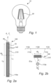
Fig. 1 schematically shows a LED filament lamp according to the prior art, comprising LED filaments, -
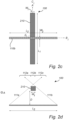
Figs. 2a-d schematically show side views and top views of portions of a LED filament arrangement according to exemplifying embodiments of the present invention, -
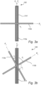
Figs. 3a-c schematically show side views of portions of a LED filament arrangement according to an embodiment of the present invention, -
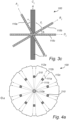
Figs. 4a ,b schematically show side views of a LED filament arrangement according to exemplifying embodiments of the present invention, -
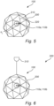
Fig. 5 schematically shows a LED filament arrangement according to an exemplifying embodiment of the present invention, and -
Fig. 6 schematically shows a lamp comprising a LED filament arrangement according to an exemplifying embodiment of the present invention. -
Fig. 1 shows aLED filament lamp 10 according to the prior art, comprising a plurality ofLED filaments 20.LED filament lamps 10 of this kind are highly appreciated as they are very decorative, as well as providing numerous advantages compared to incandescent lamps such as a longer operational life, a reduced power consumption, and an increased efficiency related to the ratio between light energy and heat energy. However, these lighting devices are often unable to provide a dynamic shadowing during operation. Hence, it is desirable to provide alternatives to existing lamps of the prior art in order to obtain a decorative lighting while at the same time providing a dynamic shadowing. -
Fig. 2a schematically shows a side view of a portion of aLED filament arrangement 100 according to an embodiment of the present invention. For reasons of simplicity, only a single (first)LED filament 110a and a singlefirst element 210 of theLED filament arrangement 100 are shown. Theelongated LED filament 110a elongates along a first axis, Ai, and the elongatedfirst element 210 elongates along a respective first element axis, Ci, wherein these axes, according to this example, are parallel to a main axis, A. Hence, a first angle, αi, between Ai and Ci, is 0° in this example. - It should be noted that the
LED filament arrangement 100 preferably comprisesN LED filaments 110a. For example, the LED filament arrangement may preferably comprise 2-10LED filaments 110a, more preferably 3-8LED filaments 110a, and even more preferred 4-6LED filaments 110a. TheLED filament 110a may preferably have a length L2 in the range from 1 cm to 20 cm, more preferably 2 cm to 12 cm, and most preferred 3 cm to 10 cm. TheLED filament 110a may preferably have a width W2 in the range from 0.5 mm to 10 mm, more preferably 0.8 mm to 8 mm, and most preferred 1 to 5 mm. The aspect ratio L2/W2 of theLED filament 110a is preferably at least 10, more preferably at least 13, and most preferred at least 15. - The
LED filament 110a comprises an array or "chain" ofLEDs 140 which is arranged on anelongated carrier 70 or substrate of theLED filament arrangement 100. For example, the array or "chain" ofLEDs 140 may comprise a plurality of adjacently arrangedLEDs 140. TheLED filament arrangement 100 preferably comprisesN LEDs 140. For example, the plurality ofLEDs 140 preferably comprises more than 20 LEDs, more preferably more than 25 LEDs, and even more preferred more than 30 LEDs. TheLEDs 140 may be equidistantly arranged on thecarrier 70. In other words, theLEDs 140 may be arranged on thecarrier 70 in a symmetric manner, wherein each LED is arranged at the same distance from adjacently arranged LEDs. - The plurality of
LEDs 140 may be direct emitting LEDs which provide a color. TheLEDs 140 are preferably blue LEDs. TheLEDs 140 may also be UV LEDs. A combination ofLEDs 140, e.g. UV LEDs and blue light LEDs, may be used. TheLEDs 140 may comprise laser diodes. The light emitted from the LED filament 120 during operation is preferably white light. The white light is preferably within 15 SDCM from the black body locus (BBL). The color temperature of the white light is preferably in the range of 2000 to 6000 K, more preferably in the range from 2100 to 5000 K, most preferably in the range from 2200 to 4000 K such as for example 2300 K or 2700 K. The white light has preferably a CRI of at least 75, more preferably at least 80, most preferably at least 85 such as for example 90 or 92. Thecarrier 70 of theLED filament arrangement 100 may be flexible, e.g. a foil. Alternatively, thecarrier 70 may be rigid, and e.g. be made of glass, quartz, sapphire and/or a polymer. - In
Fig. 2a , theLED filament 110a further comprises an elongated encapsulant comprising a light-transmissive material, wherein the encapsulant at least partially encloses the plurality ofLEDs 140. For example, the encapsulant fully encloses the plurality ofLEDs 140, and hence, also at least a portion of thecarrier 70. The encapsulant may comprise a luminescent material, which is configured to emit light under external energy excitation. For example, the luminescent material may comprise a fluorescent material. The luminescent material may comprise an inorganic phosphor, and organic phosphor and/or quantum dots/rods. The UV/blue LED light may be partially or fully absorbed by the luminescent material and converted to light of another color e.g. green, yellow, orange and/or red. For example, a UV/blue LED light may be partially or fully absorbed by the luminescent material and converted to light of another color e.g. green, yellow, orange and/or red. Preferably, the encapsulant of the LED filament is used with blue and/or UV LEDs. Furthermore, e.g. in the case of theLED filament 110a comprising RGB LEDs, the encapsulant may comprise a light scattering material to scatter the light of the (RGB) LEDs. The light scattering material may comprise light scattering particles such as e.g. BaSO4, Al2O3 and/or TiO2 particles. It will be appreciated that the light scattering material may also be applied to and/or in other components and/or portions of the LED filament arrangement. The encapsulant may further comprise silicone. The thickness of the encapsulant may preferably be constant along the length of theLED filament 110a. Furthermore, the concentration and/or type of luminescent material of the encapsulant may preferably be constant along theLED filament 110a. - In
Fig. 2a , thefirst element 210 forms part of a frame at least partially enclosing a plurality of LED filaments (of which only asingle LED filament 110a is shown) of theLED filament arrangement 100. Albeit the frame of theLED filament arrangement 100 comprises a plurality offirst elements 210, only a singlefirst element 210 is disclosed for reasons of simplicity. Thefirst element 210 has an elongated shape, such as a rod shape, and comprises a material which is at least partially opaque. Preferably, thefirst element 210 is (completely) light blocking, wherein its reflective or absorption properties is > 99%. Thefirst element 210 may be white or black or metallic. As yet another example, thefirst element 210 may be hollow, and may comprise air. The relationship between the width, Wi, of thefirst element 210 and the width, W2, of theLED filament 110a is 2W2 < W1 < 20W2, preferably 3W2 < W1 < 15W2, and even more preferred 4W2 < W1 < 10W2. Furthermore, the relationship between the width, Wi, of thefirst element 210 and the length, L2, of theLED filament 110a is 2W1 < L2, preferably 2.5W1 < L2, and even more preferred 3W1 < L2. It will be appreciated that thefirst elements 210 may have different widths. The transmittance of the plurality offirst elements 210 is preferably less than 30%, more preferred less than 10%, and most preferred less than 5%. -
Fig. 2b schematically shows a top view of a portion of aLED filament arrangement 100 according to an embodiment of the present invention. It should be noted thatFig. 2b corresponds toFig. 2a , asFig. 2b merely showsFig. 2a from another view as indicated by the axis A. Due to this, it is referred toFig. 2a for a more detailed understanding of the properties and/or embodiments of theLED filament arrangement 100. As illustrated byFig. 2b , the width, W2, of theLED filament 110a and the width, Wi, of thefirst element 210, as well as the distance, D, between theLED filament 110a and thefirst element 210 in a direction perpendicular to the axis A, influence the shadow properties of the light emitted from thelighting device 100 during operation. This is indicated by the schematically illustratedlight rays LED filament 110a during operation, resulting in illuminated portions ofspace space 112b being in shadow behind thefirst element 210. -
Fig. 2c schematically shows a side view of a portion of aLED filament arrangement 100 according to an embodiment of the present invention. For reasons of simplicity, only a single (second)LED filament 110b and a singlefirst element 210 are shown. Thesecond LED filament 110b elongates along a second axis, Bi, and the elongatedfirst element 210 elongates along the first element axis, Ci, which is parallel to the axis A. Hence, a second angle, βi, between Bi and Ci, is 90° in this example. It should be noted that the properties of theLED filament 110b ofFig. 2c corresponds to theLED filament 110a ofFig. 2a , and it is therefore referred toFig. 2a for a more detailed understanding. For example, also theLED filament 110b comprises an array or "chain" ofLEDs 140 which is arranged on an elongated carrier of theLED filament arrangement 100. Furthermore, the length L1 and width W1 of thefirst element 210 and the length L2 and width W2 of theLED filament 110b are the same as for thefirst element 210 and theLED filament 110a inFig. 2a . InFig. 2c , however, theLED filament 110b is arranged perpendicular to theLED filament 110a inFig. 2a . This will influence the properties of the shadowing during operation of theLED filament arrangement 100, which is further described inFig. 2d . -
Fig. 2d schematically shows a top view of a portion of aLED filament arrangement 100 according to an embodiment of the present invention. It should be noted thatFig. 2d corresponds toFig. 2c , asFig. 2d merely showsFig. 2c from another view as indicated by the axis A. Due to this, it is referred toFig. 2c (and alsoFig. 2a ) for a more detailed understanding of the properties and/or embodiments of theLED filament arrangement 100. As illustrated byFig. 2d , the length, L2, of theLED filament 110b and the width, Wi, of thefirst element 210 as well as the distance, D, between theLED filament 110a and thefirst element 210 in a direction perpendicular to the axis A, influence the shadow properties of the light emitted from thelighting device 100 during operation. This is indicated by the schematically illustratedlight rays LED filament 110a during operation, resulting in illuminated portions ofspace space 112b being in shadow immediately behind thefirst element 210. -
Fig. 3a schematically shows a side view of a portion of aLED filament arrangement 100 according to an embodiment of the present invention.Fig. 3a corresponds toFigs. 2a and2c , albeitFig. 3a comprises afirst LED filament 110a and asecond LED filament 110b. The first and second LED filaments 1 10a, 110b are arranged perpendicular to each other, i.e. thefirst LED filament 110a elongates along the first axis, Ai, and thesecond LED filament 110b elongates along the second axis, Bi, wherein the angle, θi, between Ai and Bi is 90°, i.e. |θi| > 10°. It will be appreciated that the first andsecond LED filaments first element 210 elongates along the first element axis, Ci, which, according to this example, is parallel to Ai and parallel to the main axis, A. Hence, a first angle, αi, between Ai and Ci, is 0° in this example. -
Fig. 3b schematically shows a side view of a portion of aLED filament arrangement 100 according to an embodiment of the present invention. Afirst LED filament 110a which elongates along a first axis, Ai, is arranged at a first angle, αi, with respect to afirst element 210 which elongates along a first element axis, Ci. Furthermore, asecond LED filament 110b which elongates along a second axis, Bi, is arranged at a second angle, βi, with respect to thefirst element 210 and the associated first element axis, Ci. In this example, α = -20° and β = 70° with respect to the axis, Ci, along which thefirst element 210 is arranged, i.e. |αi| ≠ |βi|. Furthermore, the first andsecond LED filaments -
Fig. 3c schematically shows a side view of a portion of aLED filament arrangement 100 according to an embodiment of the present invention.Fig. 3b corresponds toFig. 3a , albeitFig. 3c comprises three LED filaments, namely afirst LED filament 110a, a second LED filament 1 10b, and a third LED filament 1 10c. Thefirst LED filament 110a elongates along a first axis, Ai, thesecond LED filament 110b elongates along a second axis, Bi, and thethird LED filament 110c elongates along a third axis, Di. TheLED filaments LED filaments first element 210. For example, a first angle, αi, between the first axis Ai of thefirst LED filament 110a and the first element axis Ci, and a second angle, βi, between Bi and Ci fulfils |αi| ≠ |βi|. Furthermore, the first angle, αi, between the first axis Ai of thefirst LED filament 110a and the first element axis Ci is relatively small, e.g. |αi| < 20°, and the second angle, βi, between the second axis Bi of thesecond LED filament 110b and the first element axis Ci is relatively large, e.g. |βi| > 40°. It will be appreciated that these configurations of theLED filament arrangement 100 merely represent examples, and that substantially any other configuration of theLED filaments third LED filaments -
Fig. 4a schematically shows a top view of a portion of aLED filament arrangement 100 according to an embodiment of the present invention. It should be noted thatFig. 4a corresponds toFig. 2b , and it referred toFig. 2b for an increased understanding. InFig. 4a , there is provided afirst LED filament 110a and tenfirst elements 210 of the frame of theLED filament arrangement 100. Thefirst elements 210 are arranged parallel to the first LED filament 1 10a, i.e. thefirst elements 210 and thefirst LED filament 110a are arranged parallel to the axis A. It will be appreciated that the number offirst elements 210 with respect to thefirst element 110a is arbitrary. For example, the frame may comprise at least three, preferably at least five, and even more preferred tenfirst elements 210 for each LED filament of theLED filament arrangement 100. Furthermore, inFig. 4a , thefirst elements 210 are exemplified as being arranged symmetrically around thefirst LED filament 110a, but it should be noted that thefirst elements 210 alternatively may be arranged asymmetrically with respect to thefirst LED filament 110a. The schematically illustratedlight rays LED filament 110a during operation respectively results in illuminated portions ofspace space 112b is in shadow behind thefirst element 210. -
Fig. 4b schematically shows a top view of a portion of aLED filament arrangement 100 according to an embodiment of the present invention. It should be noted thatFig. 4b corresponds toFig. 2d , and it referred toFig. 2d for an increased understanding. InFig. 4b , there is provided afirst LED filament 110a and tenfirst elements 210 of the frame. Thefirst elements 210 are arranged perpendicular to the first LED filament 1 10a, i.e. thefirst elements 210 are arranged parallel to the axis A, and thefirst LED filament 110a is arranged perpendicular to the axis A. It will be appreciated that the number offirst elements 210 with respect to thefirst element 110a is arbitrary. For example, the frame may comprise at least three, preferably at least five, and even more preferred tenfirst elements 210 for each LED filament of theLED filament arrangement 100. The schematically illustratedlight rays LED filament 110a during operation respectively results in illuminated portions ofspace 112a,c, wherein the portion ofspace 112b is in shadow behind thefirst element 210. -
Fig. 5 schematically shows aLED filament arrangement 100 according to an embodiment of the present invention. TheLED filament 100 as exemplified comprises twoLED filaments LED filament arrangement 100 may comprise substantially any number of LED filaments. In accordance to the previously described embodiments, eachLED filament LED filaments LED filament arrangement 100 comprises aframe 200 which at least partially encloses theLED filaments frame 200 comprises a plurality offirst elements 210 of elongated shape and of a material being at least partially opaque. The plurality offirst elements 210 defines a mesh structure of theframe 200. According to an example, all first elements of the plurality offirst elements 210 may have the same shape and size (dimension). Furthermore, the plurality offirst elements 210 may be symmetrically arranged around theLED filaments LED filament arrangement 100. - A plurality of
second elements 220 of theLED filament arrangement 100 is arranged between the plurality offirst elements 210. Here, thesecond elements 220 are exemplified as being plate-shaped, but it should be noted that thesecond elements 220 may have substantially any shape. Thesecond elements 220 comprise a material being at least partially light-transmissive, such that thesecond elements 220 constitute optically transmissive portions of theframe 200. According to the example inFig. 5 , theframe 200 constituted by the arrangement of the plurality of first andsecond elements LED filaments frame 200 is preferably in the range from 1 cm to 100 cm, more preferably 3 cm to 60 cm, and even more preferred 10 to 50 cm. - The
LED filament arrangement 100 further comprises a control unit (not shown) configured to control the operation of at least one LED filament of theLED filaments LED filaments LED filaments first LED filament 110a is varied with respect to the light emitted by thesecond LED filament 110b, while the (total) light emitted by theLED filaments -
Fig. 6 schematically shows alamp 300. Thelamp 300, or luminaire, comprises aLED filament arrangement 100 according to any previously exemplified embodiment of the present invention. Theframe 200 of thelamp 300 constitutes a lamp shade, which is exemplified as a substantially spherical shape albeit its surface is faceted. The frame 200 (lamp shade) at least partially encloses theLED filaments LED filaments lamp 300. Thelamp 300 further comprises anelectrical connection 310 connected to theLED filament arrangement 100 for a supply of power to the plurality of LEDs of theLED filaments - The person skilled in the art realizes that the present invention by no means is limited to the preferred embodiments described above. On the contrary, many modifications and variations are possible within the scope of the appended claims. For example, one or more of the LED filament arrangement(s) 100, the LED filament(s) 110a, 110b, the
LEDs 140, the plurality of first and/orsecond elements
Claims (15)
- A luminaire comprising a light emitting diode, LED, filament arrangement (100) and a frame (200),the LED filament arrangement (100) comprisinga plurality of LED filaments (1 10a, 110b), each LED filament comprising an array of a plurality of light emitting diodes (120), LEDs, arranged on an elongated carrier (70), wherein at least one first LED filament (110a) of the plurality of LED filaments elongates along a respective first axis, Ai, and at least one second LED filament (110b) of the plurality of LED filaments elongates along a respective second axis, Bi, wherein at least one of a respective angle, θi, between Ai and Bi fulfils |θi| > 10°,the frame (200) at least partially enclosing the plurality of LED filaments, the frame comprising a plurality of first elements (210) of elongated shape defining a mesh structure of the frame, wherein the plurality of first elements comprises a material being at least partially opaque, wherein at least one first element of the plurality of first elements elongates along a respective first element axis, Ci, wherein a respective first angle, αi, between Ai and Ci, and wherein a respective second angle, βi, between Bi and Ci fulfils |αi| ≠ |βi|, anda control unit configured to individually control the operation of the at least one first LED filament and the at least one second LED filament of the plurality of LED filaments, such that the at least one first LED filament is arranged to emit a first light output and the at least one second LED filament is arranged to emit second light output, and said control unit is arranged to control at least one of an on/off-operation, an increasing and/or decreasing of the light intensity, a variation of the color of the light emitted from the LEDs of the plurality of LED filaments, enabling the LED filament arrangement to produce decorative light and/or dynamic shadows.
- The luminaire according to claim 1, wherein the frame further comprises a plurality of second elements (220) arranged between the plurality of first elements, wherein the plurality of second elements comprises a material being at least partially light-transmissive.
- The luminaire according to claim 1 or 2, wherein |αi| < 20° and |βi| > 40°.
- The luminaire according to any one of the preceding claims, wherein θi is in the range of 60-90°, preferably in the range of 70-90°, and even more preferred in the range of 80-90°.
- The luminaire according to any one of the preceding claims, wherein at least one third LED filament (110c) of the plurality of LED filaments elongates along a respective third axis, Di, wherein at least one of the respective angles, θi, between Ai and Bi, between Ai and Di, and between Bi and Di, respectively, fulfils |θi| > 10° and preferably wherein |θi| is in the range of 30-60°.
- The luminaire according to any one of the preceding claims, wherein said control unit further comprising a random current generator configured to supply current which varies randomly in amplitude with time to the plurality of LEDs.
- The luminaire according to any one of the preceding claims, wherein the frame comprises at least 3, preferably at least 5, and even more preferred 10 first elements which are arranged substantially parallel to a first LED filament of the plurality of LED filaments.
- The luminaire according to any one of the preceding claims, wherein the frame comprises at least 3, preferably at least 5, and even more preferred 10 first elements which are arranged substantially perpendicular to a first LED filament of the plurality of LED filaments.
- The luminaire according to any one of the preceding claims, wherein the relationship between the width, Wi, of the first elements and the width, W2, of the plurality of LED filaments is 2W2 < W1 < 20W2, preferably 3W2 < W1 < 15W2, and even more preferred 4W2 < W1 < 10W2.
- The luminaire according to any one of the preceding claims, wherein the relationship between the width, Wi, of the first elements and the length, L2, of the plurality of LED filaments is 2W1 < L2, preferably 2.5W1 < L2, and even more preferred 3W1 < L2.
- The luminaire according to any one of the preceding claims, wherein the control unit is configured to control the operation of the plurality of LED filaments such that the light emitted by the at least one first LED filament (110a) is varied with respect to the light emitted by the at least one second LED filament (110b), while the light emitted by the plurality of LED filaments is constant over time.
- The luminaire according to any one of the preceding claims, wherein each LED filament further comprises an encapsulant (250) comprising a light-transmissive material, wherein the encapsulant at least partially encloses the plurality of LEDs.
- The luminaire according to claim 12, wherein the encapsulant further comprises a luminescent material and is configured to at least partly convert the light emitted by the plurality of LEDs.
- The luminaire according to any one of the preceding claims, wherein the carrier is transparent.
- The luminaire according to any one of the preceding claims further comprising an electrical connection (310) configured to supply power to the plurality of LEDs of the plurality of LED filaments.
Applications Claiming Priority (3)
| Application Number | Priority Date | Filing Date | Title |
|---|---|---|---|
| EP20150060 | 2020-01-02 | ||
| EP20821305.8A EP4085218B1 (en) | 2020-01-02 | 2020-12-15 | Led filament arrangement |
| PCT/EP2020/086304 WO2021136657A1 (en) | 2020-01-02 | 2020-12-15 | Led filament arrangement |
Related Parent Applications (2)
| Application Number | Title | Priority Date | Filing Date |
|---|---|---|---|
| EP20821305.8A Division EP4085218B1 (en) | 2020-01-02 | 2020-12-15 | Led filament arrangement |
| EP20821305.8A Division-Into EP4085218B1 (en) | 2020-01-02 | 2020-12-15 | Led filament arrangement |
Publications (3)
| Publication Number | Publication Date |
|---|---|
| EP4538588A1 true EP4538588A1 (en) | 2025-04-16 |
| EP4538588B1 EP4538588B1 (en) | 2026-04-22 |
| EP4538588C0 EP4538588C0 (en) | 2026-04-22 |
Family
ID=69147459
Family Applications (2)
| Application Number | Title | Priority Date | Filing Date |
|---|---|---|---|
| EP24221558.0A Active EP4538588B1 (en) | 2020-01-02 | 2020-12-15 | Led filament arrangement |
| EP20821305.8A Active EP4085218B1 (en) | 2020-01-02 | 2020-12-15 | Led filament arrangement |
Family Applications After (1)
| Application Number | Title | Priority Date | Filing Date |
|---|---|---|---|
| EP20821305.8A Active EP4085218B1 (en) | 2020-01-02 | 2020-12-15 | Led filament arrangement |
Country Status (7)
| Country | Link |
|---|---|
| US (1) | US12123555B2 (en) |
| EP (2) | EP4538588B1 (en) |
| JP (1) | JP7685504B2 (en) |
| CN (1) | CN114901988B (en) |
| ES (1) | ES3021863T3 (en) |
| PL (1) | PL4085218T3 (en) |
| WO (1) | WO2021136657A1 (en) |
Families Citing this family (1)
| Publication number | Priority date | Publication date | Assignee | Title |
|---|---|---|---|---|
| CN219735142U (en) * | 2023-01-19 | 2023-09-22 | 杭州杭科光电集团股份有限公司 | Lamp tube, lamp and lamp body |
Citations (8)
| Publication number | Priority date | Publication date | Assignee | Title |
|---|---|---|---|---|
| JP2013186942A (en) * | 2012-03-05 | 2013-09-19 | Toshiba Corp | Lighting system |
| WO2018127391A1 (en) * | 2017-01-05 | 2018-07-12 | Philips Lighting Holding B.V. | Ssl lamp |
| US20180328543A1 (en) * | 2017-05-10 | 2018-11-15 | Cree, Inc. | Solid-state lamp with led filament |
| WO2019015763A1 (en) * | 2017-07-20 | 2019-01-24 | Explorentis | Led lamp with flexible led filament, and manufacturing method |
| KR101918016B1 (en) | 2018-04-16 | 2019-01-29 | 이병선 | Interior exptession divice using shade |
| US10386020B2 (en) * | 2017-06-05 | 2019-08-20 | Samsung Electronics Co., Ltd. | Light emitting diode (LED) module array and an LED lamp using the same |
| CA3013021A1 (en) | 2018-02-21 | 2019-08-21 | Feit Electric Company, Inc. | Omnidirectional light emitting diode filament holder |
| WO2019166273A1 (en) * | 2018-02-27 | 2019-09-06 | Signify Holding B.V. | Led filament lamp comprising a control unit |
Family Cites Families (10)
| Publication number | Priority date | Publication date | Assignee | Title |
|---|---|---|---|---|
| BRPI0813179A2 (en) * | 2007-04-30 | 2017-05-16 | Koninl Philips Electronics Nv | lighting system to control colored light sources, and lighting system control method |
| CN101625957A (en) * | 2008-07-08 | 2010-01-13 | 台达电子工业股份有限公司 | Fluorescent lamp capable of adjusting color temperature |
| WO2014119313A1 (en) | 2013-01-31 | 2014-08-07 | 株式会社 東芝 | Light emitting device and led light bulb |
| CN103904197B (en) | 2014-03-24 | 2017-04-12 | 东莞市华星照明实业有限公司 | LED lamp filament piece, manufacturing method of LED lamp filament piece and LED lamp filament piece bulb |
| US20150276165A1 (en) * | 2014-03-27 | 2015-10-01 | General Electric Company | Light cover |
| CN107532782B (en) | 2015-03-31 | 2020-10-13 | 昕诺飞控股有限公司 | Dynamic color shades for decorative white lighting |
| CN204592972U (en) * | 2015-05-08 | 2015-08-26 | 深圳市源磊科技有限公司 | LED bulb and LED silk |
| US20170321852A1 (en) * | 2016-04-25 | 2017-11-09 | Innovative Lighting, LLC | Modular luminaire and method of manufacture |
| US10420186B2 (en) | 2017-05-31 | 2019-09-17 | Nbcuniversal Media, Llc | Color tunable light with zone control |
| US10267484B2 (en) * | 2017-09-21 | 2019-04-23 | Evergreen Enterprises Of Virginia, Llc | Light apparatus having controlled sequenced light patterns |
-
2020
- 2020-12-15 PL PL20821305.8T patent/PL4085218T3/en unknown
- 2020-12-15 US US17/787,376 patent/US12123555B2/en active Active
- 2020-12-15 ES ES20821305T patent/ES3021863T3/en active Active
- 2020-12-15 EP EP24221558.0A patent/EP4538588B1/en active Active
- 2020-12-15 CN CN202080091660.9A patent/CN114901988B/en active Active
- 2020-12-15 EP EP20821305.8A patent/EP4085218B1/en active Active
- 2020-12-15 JP JP2022540819A patent/JP7685504B2/en active Active
- 2020-12-15 WO PCT/EP2020/086304 patent/WO2021136657A1/en not_active Ceased
Patent Citations (8)
| Publication number | Priority date | Publication date | Assignee | Title |
|---|---|---|---|---|
| JP2013186942A (en) * | 2012-03-05 | 2013-09-19 | Toshiba Corp | Lighting system |
| WO2018127391A1 (en) * | 2017-01-05 | 2018-07-12 | Philips Lighting Holding B.V. | Ssl lamp |
| US20180328543A1 (en) * | 2017-05-10 | 2018-11-15 | Cree, Inc. | Solid-state lamp with led filament |
| US10386020B2 (en) * | 2017-06-05 | 2019-08-20 | Samsung Electronics Co., Ltd. | Light emitting diode (LED) module array and an LED lamp using the same |
| WO2019015763A1 (en) * | 2017-07-20 | 2019-01-24 | Explorentis | Led lamp with flexible led filament, and manufacturing method |
| CA3013021A1 (en) | 2018-02-21 | 2019-08-21 | Feit Electric Company, Inc. | Omnidirectional light emitting diode filament holder |
| WO2019166273A1 (en) * | 2018-02-27 | 2019-09-06 | Signify Holding B.V. | Led filament lamp comprising a control unit |
| KR101918016B1 (en) | 2018-04-16 | 2019-01-29 | 이병선 | Interior exptession divice using shade |
Also Published As
| Publication number | Publication date |
|---|---|
| EP4085218C0 (en) | 2025-03-19 |
| EP4538588B1 (en) | 2026-04-22 |
| EP4538588C0 (en) | 2026-04-22 |
| JP2023509163A (en) | 2023-03-07 |
| US12123555B2 (en) | 2024-10-22 |
| WO2021136657A1 (en) | 2021-07-08 |
| CN114901988A (en) | 2022-08-12 |
| PL4085218T3 (en) | 2025-06-02 |
| EP4085218B1 (en) | 2025-03-19 |
| CN114901988B (en) | 2024-11-22 |
| JP7685504B2 (en) | 2025-05-29 |
| EP4085218A1 (en) | 2022-11-09 |
| US20220373141A1 (en) | 2022-11-24 |
| ES3021863T3 (en) | 2025-05-27 |
Similar Documents
| Publication | Publication Date | Title |
|---|---|---|
| EP3775674B1 (en) | Led filament lamp of candle light appearance | |
| CN113661572B (en) | LED filaments with light-reflecting particles used to provide flickering light. | |
| US11739886B2 (en) | LED filament arrangement | |
| US11913608B2 (en) | LED filament arrangement | |
| CN113330245B (en) | LED Filament Device | |
| EP4085218B1 (en) | Led filament arrangement | |
| EP4004432B1 (en) | Led filament arrangement | |
| WO2026017508A1 (en) | A led filament | |
| JP2022554135A (en) | LED filament configuration |
Legal Events
| Date | Code | Title | Description |
|---|---|---|---|
| PUAI | Public reference made under article 153(3) epc to a published international application that has entered the european phase |
Free format text: ORIGINAL CODE: 0009012 |
|
| STAA | Information on the status of an ep patent application or granted ep patent |
Free format text: STATUS: THE APPLICATION HAS BEEN PUBLISHED |
|
| AC | Divisional application: reference to earlier application |
Ref document number: 4085218 Country of ref document: EP Kind code of ref document: P |
|
| AK | Designated contracting states |
Kind code of ref document: A1 Designated state(s): AL AT BE BG CH CY CZ DE DK EE ES FI FR GB GR HR HU IE IS IT LI LT LU LV MC MK MT NL NO PL PT RO RS SE SI SK SM TR |
|
| STAA | Information on the status of an ep patent application or granted ep patent |
Free format text: STATUS: REQUEST FOR EXAMINATION WAS MADE |
|
| 17P | Request for examination filed |
Effective date: 20251016 |
|
| GRAP | Despatch of communication of intention to grant a patent |
Free format text: ORIGINAL CODE: EPIDOSNIGR1 |
|
| STAA | Information on the status of an ep patent application or granted ep patent |
Free format text: STATUS: GRANT OF PATENT IS INTENDED |
|
| RIC1 | Information provided on ipc code assigned before grant |
Ipc: F21K 9/232 20160101AFI20251110BHEP Ipc: F21K 9/00 20160101ALI20251110BHEP Ipc: F21V 3/02 20060101ALI20251110BHEP Ipc: F21S 8/06 20060101ALI20251110BHEP Ipc: F21Y 115/10 20160101ALN20251110BHEP Ipc: H01L 25/075 20060101ALN20251110BHEP |
|
| INTG | Intention to grant announced |
Effective date: 20251126 |
|
| GRAS | Grant fee paid |
Free format text: ORIGINAL CODE: EPIDOSNIGR3 |
|
| GRAA | (expected) grant |
Free format text: ORIGINAL CODE: 0009210 |
|
| STAA | Information on the status of an ep patent application or granted ep patent |
Free format text: STATUS: THE PATENT HAS BEEN GRANTED |
|
| AC | Divisional application: reference to earlier application |
Ref document number: 4085218 Country of ref document: EP Kind code of ref document: P |
|
| AK | Designated contracting states |
Kind code of ref document: B1 Designated state(s): AL AT BE BG CH CY CZ DE DK EE ES FI FR GB GR HR HU IE IS IT LI LT LU LV MC MK MT NL NO PL PT RO RS SE SI SK SM TR |
|
| REG | Reference to a national code |
Ref country code: CH Ref legal event code: F10 Free format text: ST27 STATUS EVENT CODE: U-0-0-F10-F00 (AS PROVIDED BY THE NATIONAL OFFICE) Effective date: 20260422 Ref country code: GB Ref legal event code: FG4D |
|
| REG | Reference to a national code |
Ref country code: DE Ref legal event code: R096 Ref document number: 602020071026 Country of ref document: DE |
|
| REG | Reference to a national code |
Ref country code: IE Ref legal event code: FG4D |
|
| U01 | Request for unitary effect filed |
Effective date: 20260512 |
|
| U07 | Unitary effect registered |
Designated state(s): AT BE BG DE DK EE FI FR IT LT LU LV MT NL PT RO SE SI Effective date: 20260521 |