EP4538571A1 - Electric valve control device and electric valve device - Google Patents
Electric valve control device and electric valve device Download PDFInfo
- Publication number
- EP4538571A1 EP4538571A1 EP23819629.9A EP23819629A EP4538571A1 EP 4538571 A1 EP4538571 A1 EP 4538571A1 EP 23819629 A EP23819629 A EP 23819629A EP 4538571 A1 EP4538571 A1 EP 4538571A1
- Authority
- EP
- European Patent Office
- Prior art keywords
- magnetic sensor
- magnet rotor
- valve
- electric valve
- control device
- Prior art date
- Legal status (The legal status is an assumption and is not a legal conclusion. Google has not performed a legal analysis and makes no representation as to the accuracy of the status listed.)
- Pending
Links
Images








Classifications
-
- F—MECHANICAL ENGINEERING; LIGHTING; HEATING; WEAPONS; BLASTING
- F25—REFRIGERATION OR COOLING; COMBINED HEATING AND REFRIGERATION SYSTEMS; HEAT PUMP SYSTEMS; MANUFACTURE OR STORAGE OF ICE; LIQUEFACTION SOLIDIFICATION OF GASES
- F25B—REFRIGERATION MACHINES, PLANTS OR SYSTEMS; COMBINED HEATING AND REFRIGERATION SYSTEMS; HEAT PUMP SYSTEMS
- F25B41/00—Fluid-circulation arrangements
- F25B41/30—Expansion means; Dispositions thereof
- F25B41/31—Expansion valves
- F25B41/34—Expansion valves with the valve member being actuated by electric means, e.g. by piezoelectric actuators
- F25B41/35—Expansion valves with the valve member being actuated by electric means, e.g. by piezoelectric actuators by rotary motors, e.g. by stepping motors
-
- F—MECHANICAL ENGINEERING; LIGHTING; HEATING; WEAPONS; BLASTING
- F16—ENGINEERING ELEMENTS AND UNITS; GENERAL MEASURES FOR PRODUCING AND MAINTAINING EFFECTIVE FUNCTIONING OF MACHINES OR INSTALLATIONS; THERMAL INSULATION IN GENERAL
- F16K—VALVES; TAPS; COCKS; ACTUATING-FLOATS; DEVICES FOR VENTING OR AERATING
- F16K31/00—Actuating devices; Operating means; Releasing devices
- F16K31/02—Actuating devices; Operating means; Releasing devices electric; magnetic
- F16K31/04—Actuating devices; Operating means; Releasing devices electric; magnetic using a motor
- F16K31/046—Actuating devices; Operating means; Releasing devices electric; magnetic using a motor with electric means, e.g. electric switches, to control the motor or to control a clutch between the valve and the motor
-
- F—MECHANICAL ENGINEERING; LIGHTING; HEATING; WEAPONS; BLASTING
- F16—ENGINEERING ELEMENTS AND UNITS; GENERAL MEASURES FOR PRODUCING AND MAINTAINING EFFECTIVE FUNCTIONING OF MACHINES OR INSTALLATIONS; THERMAL INSULATION IN GENERAL
- F16K—VALVES; TAPS; COCKS; ACTUATING-FLOATS; DEVICES FOR VENTING OR AERATING
- F16K37/00—Special means in or on valves or other cut-off apparatus for indicating or recording operation thereof, or for enabling an alarm to be given
- F16K37/0025—Electrical or magnetic means
- F16K37/0041—Electrical or magnetic means for measuring valve parameters
-
- H—ELECTRICITY
- H02—GENERATION; CONVERSION OR DISTRIBUTION OF ELECTRIC POWER
- H02K—DYNAMO-ELECTRIC MACHINES
- H02K11/00—Structural association of dynamo-electric machines with electric components or with devices for shielding, monitoring or protection
- H02K11/20—Structural association of dynamo-electric machines with electric components or with devices for shielding, monitoring or protection for measuring, monitoring, testing, protecting or switching
- H02K11/21—Devices for sensing speed or position, or actuated thereby
- H02K11/215—Magnetic effect devices, e.g. Hall-effect or magneto-resistive elements
-
- H—ELECTRICITY
- H02—GENERATION; CONVERSION OR DISTRIBUTION OF ELECTRIC POWER
- H02K—DYNAMO-ELECTRIC MACHINES
- H02K37/00—Motors with rotor rotating step by step and without interrupter or commutator driven by the rotor, e.g. stepping motors
- H02K37/10—Motors with rotor rotating step by step and without interrupter or commutator driven by the rotor, e.g. stepping motors of permanent magnet type
- H02K37/12—Motors with rotor rotating step by step and without interrupter or commutator driven by the rotor, e.g. stepping motors of permanent magnet type with stationary armatures and rotating magnets
- H02K37/14—Motors with rotor rotating step by step and without interrupter or commutator driven by the rotor, e.g. stepping motors of permanent magnet type with stationary armatures and rotating magnets with magnets rotating within the armatures
-
- H—ELECTRICITY
- H02—GENERATION; CONVERSION OR DISTRIBUTION OF ELECTRIC POWER
- H02P—CONTROL OR REGULATION OF ELECTRIC MOTORS, ELECTRIC GENERATORS OR DYNAMO-ELECTRIC CONVERTERS; CONTROLLING TRANSFORMERS, REACTORS OR CHOKE COILS
- H02P29/00—Arrangements for regulating or controlling electric motors, appropriate for both AC and DC motors
- H02P29/02—Providing protection against overload without automatic interruption of supply
- H02P29/024—Detecting a fault condition, e.g. short circuit, locked rotor, open circuit or loss of load
-
- H—ELECTRICITY
- H02—GENERATION; CONVERSION OR DISTRIBUTION OF ELECTRIC POWER
- H02P—CONTROL OR REGULATION OF ELECTRIC MOTORS, ELECTRIC GENERATORS OR DYNAMO-ELECTRIC CONVERTERS; CONTROLLING TRANSFORMERS, REACTORS OR CHOKE COILS
- H02P8/00—Arrangements for controlling dynamo-electric motors rotating step by step
- H02P8/24—Arrangements for stopping
-
- H—ELECTRICITY
- H02—GENERATION; CONVERSION OR DISTRIBUTION OF ELECTRIC POWER
- H02P—CONTROL OR REGULATION OF ELECTRIC MOTORS, ELECTRIC GENERATORS OR DYNAMO-ELECTRIC CONVERTERS; CONTROLLING TRANSFORMERS, REACTORS OR CHOKE COILS
- H02P8/00—Arrangements for controlling dynamo-electric motors rotating step by step
- H02P8/34—Monitoring operation
-
- F—MECHANICAL ENGINEERING; LIGHTING; HEATING; WEAPONS; BLASTING
- F25—REFRIGERATION OR COOLING; COMBINED HEATING AND REFRIGERATION SYSTEMS; HEAT PUMP SYSTEMS; MANUFACTURE OR STORAGE OF ICE; LIQUEFACTION SOLIDIFICATION OF GASES
- F25B—REFRIGERATION MACHINES, PLANTS OR SYSTEMS; COMBINED HEATING AND REFRIGERATION SYSTEMS; HEAT PUMP SYSTEMS
- F25B49/00—Arrangement or mounting of control or safety devices
- F25B49/02—Arrangement or mounting of control or safety devices for compression type machines, plants or systems
-
- H—ELECTRICITY
- H02—GENERATION; CONVERSION OR DISTRIBUTION OF ELECTRIC POWER
- H02K—DYNAMO-ELECTRIC MACHINES
- H02K2211/00—Specific aspects not provided for in the other groups of this subclass relating to measuring or protective devices or electric components
- H02K2211/03—Machines characterised by circuit boards, e.g. pcb
-
- H—ELECTRICITY
- H02—GENERATION; CONVERSION OR DISTRIBUTION OF ELECTRIC POWER
- H02K—DYNAMO-ELECTRIC MACHINES
- H02K2213/00—Specific aspects, not otherwise provided for and not covered by codes H02K2201/00 - H02K2211/00
- H02K2213/03—Machines characterised by numerical values, ranges, mathematical expressions or similar information
-
- Y—GENERAL TAGGING OF NEW TECHNOLOGICAL DEVELOPMENTS; GENERAL TAGGING OF CROSS-SECTIONAL TECHNOLOGIES SPANNING OVER SEVERAL SECTIONS OF THE IPC; TECHNICAL SUBJECTS COVERED BY FORMER USPC CROSS-REFERENCE ART COLLECTIONS [XRACs] AND DIGESTS
- Y02—TECHNOLOGIES OR APPLICATIONS FOR MITIGATION OR ADAPTATION AGAINST CLIMATE CHANGE
- Y02B—CLIMATE CHANGE MITIGATION TECHNOLOGIES RELATED TO BUILDINGS, e.g. HOUSING, HOUSE APPLIANCES OR RELATED END-USER APPLICATIONS
- Y02B30/00—Energy efficient heating, ventilation or air conditioning [HVAC]
- Y02B30/70—Efficient control or regulation technologies, e.g. for control of refrigerant flow, motor or heating
Definitions
- the present invention relates to an electric valve control device and an electric valve device including an electric valve and the electric valve control device.
- an electric valve control device is an electric valve control device for controlling an electric valve.
- the stepping motor includes a magnet rotor that has a circular cylindrical shape and is disposed inside the can and a stator that is disposed outside the can.
- North poles and south poles are alternately arranged on an outer circumferential surface of the magnet rotor at regular intervals in a circumferential direction.
- the electric valve control device is configured to detect that rotation of the magnet rotor is restricted using the output signal of the first magnetic sensor and the output signal of the second magnetic sensor and output-signal expected value information that serves as expected values of the output signal of the first magnetic sensor and the output signal of the second magnetic sensor while the magnet rotor rotates.
- the electric valve includes a valve body that has a valve port, a valve member that faces the valve port, a can that is bonded to the valve body, a stepping motor for moving the valve member, and a first magnetic sensor and a second magnetic sensor that are disposed outside the can.
- the stepping motor includes a magnet rotor that has a circular cylindrical shape and is disposed inside the can and a stator that is disposed outside the can.
- the electric valve control device is configured to detect position and rotation direction of the magnet rotor using an output signal of the first magnetic sensor and an output signal of the second magnetic sensor.
- the electric valve control device is configured to detect that the rotation of the magnet rotor is restricted using the output signals of the first and second magnetic sensors and the output-signal expected value information that serves as the expected values of the output signals while the magnet rotor rotates.
- the electric valve control device can determine whether the magnet rotor is rotating by comparing the output signals of the first and second magnetic sensors and the output-signal expected value information that serves as the expected values of the output signals. Therefore, it can be detected in a relatively simple way that the rotation of the magnet rotor is restricted, based on the determination of the rotation of the magnet rotor.
- Fig. 6 the can and the magnet rotor are illustrated in sections cut along a plane that includes an upper surface of the stator, and the sensor circuit board and the first and second magnetic sensors are represented in dashed lines.
- Fig. 6 hatched areas schematically represent north poles of the magnet rotor, and dotted areas schematically represent south poles of the magnet rotor.
- Fig. 7 is a diagram schematically illustrating a positional relationship between pole teeth of the stator and the first and second magnetic sensors that are included in the electric valve.
- Fig. 8 is a perspective view of a control circuit board of the electric valve control device.
- Fig. 9 is a diagram illustrating a microcomputer, a stepping motor, and the first and second magnetic sensors.
- FIG. 9A schematically illustrates a connection relationship between the microcomputer, the stepping motor, and the first and second magnetic sensors.
- Fig. 9B illustrates an example of pulses input to the stepping motor.
- an X direction indicated by arrow X represents a left-and-right direction
- a Y direction indicated by arrow Y represents a front-and-back direction
- a Z direction indicated by arrow Z represents an up-and-down direction.
- the direction denoted by "X" on arrow X is a right direction
- the direction denoted by "Y" on arrow Y is a front direction
- the direction denoted by "Z" on arrow Z is an upward direction.
- An electric valve device 1 includes an electric valve 5 and the electric valve control device.
- the electric valve control device is simply referred to as "a control device 100".
- the electric valve device 1 is installed in an air conditioner system 400 illustrated in Fig. 1 .
- the air conditioner system 400 includes a compressor 401, a condenser 402, the electric valve device 1 (the electric valve 5), and an evaporator 403, which are connected in this order by a pipe 405.
- the air conditioner system 400 includes an air conditioner control device 410.
- the air conditioner control device 410 is connected to the electric valve device 1 (the control device 100) via a communication bus 420 and is able to communicate with the electric valve device 1.
- the air conditioner control device 410 utilizes the electric valve device 1 to control the flow rate of refrigerant flowing through the pipe 405.
- the flow channel 16 is connected to the valve chamber 14 through the valve port 17.
- the valve seat 18 encloses the valve port 17 in the valve chamber 14.
- the connection member 13 has a circular annular plate-like shape. The upper part of the supporting member 12 is bonded to the inner peripheral edge of the connection member 13.
- the can 20 is, for example, made of a metal, such as stainless steel.
- the can 20 has a circular cylindrical shape.
- the can 20 is closed at the upper end and is open at the lower end.
- the lower end of the can 20 is bonded to the outer peripheral edge of the connection member 13.
- the driving mechanism 30 moves the valve member 40 in the up-and-down direction (a direction of an axis L).
- the driving mechanism 30 includes a magnet rotor 31, a valve stem holder 32, a guide bush 33, and a valve stem 34.
- the valve stem holder 32 has a circular cylindrical shape.
- the valve stem holder 32 is closed at the upper end and is open at the lower end.
- a supporting ring 35 is secured to the upper part of the valve stem holder 32.
- the valve stem holder 32 is coupled to the magnet rotor 31 via the supporting ring 35.
- the valve stem holder 32 rotates together with the magnet rotor 31.
- the inner circumferential surface of the valve stem holder 32 has an internal thread 32c.
- a movable stopper 32s is secured to the valve stem holder 32.
- a fixed stopper 33s is secured to the first circular cylindrical portion 33a of the guide bush 33.
- rotation of the valve stem holder 32 i.e., the magnet rotor 31
- the movable stopper 32s and the fixed stopper 33s are members of a stopper mechanism 38.
- the stopper mechanism 38 restricts rotation of the magnet rotor 31 in the valve closing direction.
- the valve stem 34 integrally includes a first part 34a and a second part 34b.
- the first part 34a and the second part 34b each have a circular columnar shape.
- the diameter of the second part 34b is smaller than that of the first part 34a.
- the second part 34b is coaxially connected to the upper end of the first part 34a.
- the second part 34b extends through the valve stem holder 32.
- a push nut 36 as a retainer is mounted on the second part 34b.
- the valve stem 34 is disposed inside both the guide bush 33 and the supporting member 12.
- the lower end of the first part 34a is disposed in the valve chamber 14.
- the valve stem 34 has a step portion 34d.
- the step portion 34d is disposed in the part where the second part 34b is connected to the first part 34a.
- a valve closing spring 37 is disposed between the step portion 34d and the valve stem holder 32.
- the valve closing spring 37 is a compression coil spring. The valve closing spring 37 pushes the valve
- the valve member 40 is disposed in the valve chamber 14.
- the valve member 40 faces the valve port 17 in the up-and-down direction.
- the valve member 40 opens and closes the valve port 17.
- the valve member 40 is connected to the lower end of the valve stem 34.
- the valve stem 34 and the valve member 40 are integrally formed by cutting a workpiece with a circular columnar shape.
- the stator unit 50 includes a stator 60, a housing 70, and a case 80.
- the A-phase stator 61 is disposed coaxially with the B-phase stator 62.
- the A-phase stator 61 is in contact with the B-phase stator 62 .
- the angle between the pole tooth 61a of the A-phase stator 61 and the pole tooth 62a of the B-phase stator 62 adjacent to each other is 7.5 degrees.
- the coil 61c of the A-phase stator 61 and the coil 62c of the B-phase stator 62 are connected to terminals 65 .
- the housing 70 is made of synthetic resin.
- the housing 70 has a circular cylindrical shape.
- the housing 70 is formed by injection molding.
- the housing 70 houses the stator 60.
- the housing 70 is formed by integrally molding (insert molding) with the stator 60.
- the stator 60 and the housing 70 may be manufactured separately, and the stator 60 may be fitted into the housing 70.
- the can 20 is disposed in an inner space 74 that is defined by the inner surface of the housing 70 and the inner circumferential surface of the stator 60 .
- the stator 60 and the magnet rotor 31 are members of a stepping motor 66 .
- the housing 70 has a circuit board space 75.
- the circuit board space 75 extends in a lateral direction (a direction perpendicular to the axis L).
- the circuit board space 75 is situated adjacent to the inner space 74.
- a partition wall 76 is placed between the inner space 74 and the circuit board space 75.
- the partition wall 76 separates the circuit board space 75 from the inner space 74.
- the cross section (a section perpendicular to the axis L) of the partition wall 76 has an arc shape along with the outer circumferential surface of the can 20.
- the case 80 is made of synthetic resin.
- the case 80 has a rectangular parallelepiped box shape.
- the case 80 is bonded to the housing 70.
- a space 85 is provided inside the case 80 and is connected to the circuit board space 75 through an opening 80a.
- a connector 83 is provided in the upper part of the case 80.
- the first magnetic sensor 91 and the second magnetic sensor 92 are each radially positioned relative to the magnet rotor 31 with the can 20 and the partition wall 76 in between. In other words, the first magnetic sensor 91 and the second magnetic sensor 92 each radially (laterally) face the magnet rotor 31 with the can 20 and the partition wall 76 in between.
- Fig. 6 illustrates an example of an arrangement of the first magnetic sensor 91 and the second magnetic sensor 92.
- a line M1 connects the axis L and a magnetic sensing section of the first magnetic sensor 91
- a line M2 connects the axis L and a magnetic sensing section of the second magnetic sensor 92.
- the lines M1 and M2 intersect the axis L at right angles.
- n represents the number of the magnetic poles of the magnet rotor 31
- N represents a natural number
- ⁇ represents an angle, as viewed in the direction (the direction of the axis L) of the axis of the magnet rotor 31, between the lines M1 and M2, the following expression (1) is satisfied.
- ⁇ 360 / n ⁇ N + 360 / 2 n ,
- the second magnetic sensor 92 when the first magnetic sensor 91 radially faces one of the magnetic poles (the N and S poles) of the magnet rotor 31 , the second magnetic sensor 92 radially faces a portion of the outer circumferential surface between the N pole and the S pole of the magnet rotor 31.
- the first magnetic sensor 91 when the second magnetic sensor 92 radially faces one of the magnetic poles (the N and S poles) of the magnet rotor 31, the first magnetic sensor 91 radially faces a portion of the outer circumferential surface between the N pole and the S pole of the magnet rotor 31.
- Fig. 7 illustrates an example of a positional relationship between the A-phase stator 61, the B-phase stator 62, the first magnetic sensor 91, and the second magnetic sensor 92.
- the center of the pole tooth 61a of the A-phase stator 61 and the magnetic sensing section of the first magnetic sensor 91 are positioned on a line L1
- the center of the pole tooth 62a of the B-phase stator 62 and the magnetic sensing section of the second magnetic sensor 92 are positioned on a line L2.
- the lines L1 and L2 are parallel to the axis L.
- the respective central axes of the body member 11 (the valve port 17 and the valve seat 18), the supporting member 12, the connection member 13, the can 20, the magnet rotor 31, the valve stem 34, the valve member 40, and the stator 60 (the A-phase stator 61 and the B-phase stator 62) are aligned with the axis L.
- the control device 100 includes a control circuit board 110 and a microcomputer 120.
- Fig. 8 illustrates the control circuit board 110.
- the control circuit board 110 is a printed circuit board on which electronic components are mounted.
- the control circuit board 110 is housed in the space 85 of the case 80.
- the control circuit board 110 is positioned in the up-and-down direction.
- the control circuit board 110 is at a right angle to the sensor circuit board 90.
- the control circuit board 110 is disposed near the first end 90a of the sensor circuit board 90.
- the control circuit board 110 is connected to the sensor circuit board 90 via connecting terminals 93.
- the terminals 65 of the stator 60 are connected to the control circuit board 110.
- the bosses 87 of the case 80 are disposed in through holes 112 of the control circuit board 110, and the control circuit board 110 is mounted on the bosses 87.
- the microcomputer 120 is mounted on the control circuit board 110.
- the microcomputer 120 is, for example, a microcomputer for embedded device in which a central processing unit (a CPU 121), a non-volatile memory 122, a motor driver 123, a working memory 124, a communication module 125, and the like are integrated into one package.
- the microcomputer 120 controls the electric valve 5.
- a non-volatile memory, a working memory, a communication module, and a motor driver may be separate electronic components that are externally connected to the microcomputer 120.
- the magnet rotor 31 is rotated by pulses P (pulses P[1] to P[8]) input to the stepping motor 66. Specifically, the magnet rotor 31 is rotated by the driving currents, corresponding to pulses P, supplied to the stator 60 of the stepping motor 66.
- pulses P are repeatedly input to the stepping motor 66 in ascending or descending order. In other words, pulses P[1] to P[8] are pulses P for one cycle and are multiple pulses P repeatedly input to the stepping motor 66 in a predetermined order.
- Pulses P[1] to P[8] illustrated in Fig. 9B are input to the stepping motor 66 in order.
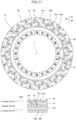
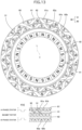
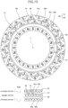
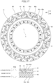
- Figs. 10 to 17 schematically illustrate examples of a positional relationship between the magnet rotor 31 and the stator 60 when pulses P[1] to P[8] are input.
- Figs. 10 to 17 schematically illustrate the magnetic poles of the magnet rotor 31 and the pole teeth of the stator 60.
- the radially outward direction in upper diagrams of Figs. 10 to 17 corresponds to the upward direction, and the radially inward direction corresponds to a downward direction.
- Figs. 10 to 17 schematically illustrate examples of a positional relationship between the magnet rotor 31 and the stator 60 when pulses P[1] to P[8] are input.
- Figs. 10 to 17 schematically illustrate the magnetic poles of the magnet rotor 31 and the pole teeth of the stator 60.
- the radially outward direction in upper diagrams of Figs. 10 to 17 correspond
- the reference pole tooth 61a and the reference magnetic pole (the S pole) of the magnet rotor 31 are marked with a dot for easy understanding of the positional relationship between the magnet rotor 31 and the stator 60 (the A-phase stator 61 and the B-phase stator 62).
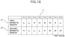
- Fig. 18 illustrates an example of output-signal expected value information J (J1 and J2) of the first magnetic sensor 91 and the second magnetic sensor 92.
- the output-signal expected value information J serves as expected values of the output signals K of the first magnetic sensor 91 and the second magnetic sensor 92 when pulses P[1] to P[8] are input to the stepping motor 66.
- the output-signal expected value information J is stored in the non-volatile memory 122.
- 'L' indicates the L signal
- 'H' indicates the H signal
- '*' indicates that either 'L' or 'H' (any value) is acceptable.
- the output-signal expected value information J1 of the first magnetic sensor 91 is illustrated in the upper part of Fig. 18 .
- the output-signal expected value information J2 of the second magnetic sensor 92 is illustrated in the lower part of Fig. 18 .
- the expected values of the output signals K of the first magnetic sensor 91 and the second magnetic sensor 92 when pulse P[1] is input to the stepping motor 66 are 'L' and '*'.
- the expected values of the output signals K of the first magnetic sensor 91 and the second magnetic sensor 92 when pulse P[2] is input to the stepping motor 66 are 'L' and 'L'.
- the expected values of the output signals K of the first magnetic sensor 91 and the second magnetic sensor 92 when pulse P[3] is input to the stepping motor 66 are '*' and 'L'.
- the expected values of the output signals K of the first magnetic sensor 91 and the second magnetic sensor 92 when pulse P[5] is input to the stepping motor 66 are 'H' and '*'.
- the expected values of the output signals K of the first magnetic sensor 91 and the second magnetic sensor 92 when pulse P[6] is input to the stepping motor 66 are 'H' and 'H'.
- the expected values of the output signals K of the first magnetic sensor 91 and the second magnetic sensor 92 when pulse P[7] is input to the stepping motor 66 are '*' and 'H'.
- the expected values of the output signals K of the first magnetic sensor 91 and the second magnetic sensor 92 when pulse P[8] is input to the stepping motor 66 are 'L' and 'H'.
- the first magnetic sensor 91 when the magnet rotor 31 rotates in the valve closing direction, the first magnetic sensor 91 outputs "LLHHHHLL” as the output signal K1, and the second magnetic sensor 92 outputs "LLLLHHHH” as the output signal K2, in correspondence with pulses P[1] to P[8] being input.
- the first magnetic sensor 91 outputs "LLHHHHLL”, and the second magnetic sensor 92 outputs "HHHHLLLL”, in correspondence with pulses P[8] to P[1] being input.
- the output signals K1 and K2 change according to the rotation of the magnet rotor 31. Consequently, the control device 100 can detect the position and the rotation direction of the magnet rotor 31 using the output signals K1 and K2.
- the position of the magnet rotor 31 corresponds to, for example, the rotation angle of the magnet rotor 31 from the reference position Rx.
- the magnet rotor 31 When the output signals K of the first magnetic sensor 91 and the second magnetic sensor 92 match the output-signal expected value information J, the magnet rotor 31 is rotating. When at least one of the output signals K of the first magnetic sensor 91 and the second magnetic sensor 92 does not match the output-signal expected value information J, the magnet rotor 31 is not rotating.
- the reference pole tooth 61a and the reference magnetic pole (the S pole) of the magnet rotor 31 are marked with a black square for easy understanding of the positional relationship between the magnet rotor 31 and the stator 60 (the A-phase stator 61 and the B-phase stator 62).
- the right direction corresponds to the valve closing direction
- the left direction corresponds to the valve opening direction.
- Figs. 20A to 20E and 21A to 21D correspond to times T401 to T409 in Fig. 19 .
- the magnet rotor 31 rotates in the valve closing direction by the step angle with each pulse.
- the control device 100 inputs pulse P[1] to the stepping motor 66 at time T401, as illustrated in Fig. 20A , the magnet rotor 31 is positioned at the reference position Rx, and the movable stopper 32s comes into contact with the fixed stopper 33s.
- the rotation of the magnet rotor 31 in the valve closing direction is restricted at the reference position Rx.
- the magnet rotor 31 rotates in the valve closing direction after each pulse P is input from times T1 to T401, and the output signals K match the output-signal expected value information J.
- the control device 100 inputs pulses P[2], P[3], P[4], and P[5] to the stepping motor 66 at times T402, T403, T404, and T405, as illustrated in Figs. 20B to 20E , the magnet rotor 31 does not rotate in the valve closing direction, and the output signals K do not change.
- the output signals K match the output-signal expected value information J after each pulse P is input at times T402 and T403 but do not match the output-signal expected value information J after each pulse P is input at times T404 and T405.
- the output signal K1 does not match the output-signal expected value information J1.
- hatched areas represent some of the output signals K that do not match the output-signal expected value information J.
- the control device 100 inputs pulse P[6] to the stepping motor 66 at time T406, as illustrated in Fig. 20A , the magnet rotor 31 rotates in the valve opening direction.
- the rotation angle of the magnet rotor 31 is three times the step angle.
- the output signals K become values corresponding to pulse P[6].
- the output signals K after pulse P is input at time T406 match the output-signal expected value information J.
- the magnet rotor 31 rotates in the valve closing direction by the step angle with each pulse.
- the output signals K after each pulse P is input at times T407, T408, and T409 match the output-signal expected value information J.
- the magnet rotor 31 is positioned at the reference position Rx again after pulse P is input at the T409, and the rotation of the magnet rotor 31 in the valve closing direction is restricted by the stopper mechanism 38.
- the output signals K repeatedly change in the same manner as times T401 to T408 in response to pulses P[1] to P[8] being input.
- the control device 100 can determine whether the magnet rotor 31 is rotating by comparing the output signals K of the first magnetic sensor 91 and the second magnetic sensor 92 obtained after each pulse P is input with the output-signal expected value information J.
- the control device 100 can detect that the rotation of the magnet rotor 31 is restricted, based on the determination.
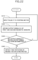
- the control device 100 (specifically, the CPU 121) inputs pulse P to the stepping motor 66 in ascending order (S110).
- the control device 100 obtains the output signals K of the first magnetic sensor 91 and the second magnetic sensor 92 (S120).
- the control device 100 reads the output-signal expected value information J, corresponding to pulse P being input, from the non-volatile memory 122 to compare the output signals K with the output-signal expected value information J (S130). When the output signals K match the output-signal expected value information J (Y in S130), the control device 100 determines that the magnet rotor 31 is rotating and inputs next pulse P (return to S110).
- the control device 100 determines that the magnet rotor 31 is not rotating and detects that the rotation of the magnet rotor 31 in the valve closing direction is restricted (S140). As a result, the control device 100 determines that the magnet rotor 31 is positioned at the reference position Rx and finishes the process.
- the control device 100 can detect that the rotation of the magnet rotor 31 in the valve closing direction is restricted by the stopper mechanism 38. Additionally, the control device 100 can detect, for example, that the rotation of the magnet rotor 31 is restricted due to foreign matters contained in refrigerant.
- the magnet rotor 31 can rotate in the valve opening direction.
- the magnet rotor 31 can rotate by an angle corresponding to the play between the internal thread 32c of the valve stem holder 32 and the external thread 33c of the guide bush 33.
- pulses P when pulses P are sequentially input to rotate the magnet rotor 31 in one direction (the valve closing direction or the valve opening direction) and continue to be input even after the rotation of the magnet rotor 31 is restricted, the magnet rotor 31 repeatedly exhibits a movement in which the magnet rotor 31 temporarily rotates in the opposite direction before resuming its original rotation. This movement is referred to as "a reverse rotation movement".
- the control device 100 can determine that the rotation restriction corresponds to type (i) or (ii) when the magnet rotor 31 exhibits the reverse rotation movement and to type (iii) when the magnet rotor 31 does not exhibit the reverse rotation movement.
- the control device 100 may be configured to send a malfunction alert for the electric valve 5 to the air conditioner control device 410 when the rotation restriction of the magnet rotor 31 corresponds to type (iii) and is not eliminated even though an attempt is made to rotate the magnet rotor 31 in the opposite direction.
- the electric valve device 1 includes the electric valve 5 and the control device 100.
- the electric valve 5 includes the valve body 10 that has the valve port 17, the valve member 40 that faces the valve port 17, the can 20 that is bonded to the valve body 10, the stepping motor 66 for moving the valve member 40, the first magnetic sensor 91, and the second magnetic sensor 92.
- the stepping motor 66 includes the magnet rotor 31 that has a circular cylindrical shape and is disposed inside the can 20 and the stator 60 that is disposed outside the can 20.
- the N poles and the S poles are alternately arranged on the outer circumferential surface of the magnet rotor 31 at regular intervals in the circumferential direction.
- the first magnetic sensor 91 and the second magnetic sensor 92 are disposed outside the can 20 and are radially positioned relative to the magnet rotor 31.
- n represents the total number of the N poles and the S poles
- N represents a natural number
- ⁇ represents the angle between the line M1 connecting the axis L (the axis of the magnet rotor 31) to the first magnetic sensor 91 and the line M2 connecting the axis L to the second magnetic sensor 92
- the output signals K of the first magnetic sensor 91 and the second magnetic sensor 92 are each a binary signal.
- the control device 100 detects that the rotation of the magnet rotor 31 is restricted using the output signals K and the output-signal expected value information J.
- the control device 100 may be configured to detect the rotation direction of the magnet rotor 31 using the output signals K of the first magnetic sensor 91 and the second magnetic sensor 92.
- the magnet rotor 31 rotates in the valve opening direction when the control device 100 inputs pulses P to the stepping motor 66 in descending order.
- the output signal K2 of the second magnetic sensor 92 changes from 'L' to 'H' in response to pulses P[2], P[1], and P[8] being input, and the output signal K1 of the first magnetic sensor 91 changes from 'L' to 'H' in response to pulses P[8], P[7], and P[6] being input.
- the output signal K of the first magnetic sensor 91 changes from 'L' to 'H', followed by the output signal K of the second magnetic sensor 92 changing from 'L' to 'H'.
- the output signal K of the second magnetic sensor 92 changes from 'L' to 'H', followed by the output signal K of the first magnetic sensor 91 changing from 'L' to 'H'.
- the control device 100 can detect, in a relatively simple way, the rotation direction of the magnet rotor 31 using timing when the output signal K of the first magnetic sensor 91 changes from the L signal (the first value) to the H signal (the second value) and timing when the output signal K of the second magnetic sensor 92 changes from the L signal (the first value) to the H signal (the second value).
- the L and H signals may be assigned as the second and first values, respectively.
- circular cylindrical member includes a circular cylindrical member and a substantially circular cylindrical member.
- step portion 35 ... supporting ring, 36 ... push nut, 37 ... valve closing spring, 38 ... stopper mechanism, 40 ... valve member, 50 ... stator unit, 60 ... stator, 61 ... A-phase stator, 61a, 61b ... pole tooth, 61c ... coil, 62 ... B-phase stator, 62a, 62b ... pole tooth, 62c ... coil, 65 ... terminal, 66 ... stepping motor, 70 ... housing, 74 ... inner space, 75 ... circuit board space, 76 ... partition wall, 80 ... case, 80a ... opening, 83 ... connector, 85 ... space, 87 ... boss, 90 ... sensor circuit board, 90a ...
Landscapes
- Engineering & Computer Science (AREA)
- General Engineering & Computer Science (AREA)
- Power Engineering (AREA)
- Mechanical Engineering (AREA)
- Physics & Mathematics (AREA)
- Thermal Sciences (AREA)
- Microelectronics & Electronic Packaging (AREA)
- Electrically Driven Valve-Operating Means (AREA)
- Indication Of The Valve Opening Or Closing Status (AREA)
- Control Of Stepping Motors (AREA)
Abstract
[Object] To provide an electric valve control device and an electric valve device that are capable of detecting in a relatively simple way that rotation of a magnet rotor is restricted.
[Solution] An electric valve control device controls an electric valve. The electric valve includes a first magnetic sensor (91) and a second magnetic sensor (92). Output signals of the first magnetic sensor (91) and the second magnetic sensor (92) are each a binary signal. Where n represents the total number of north poles and south poles of a magnet rotor (31), N represents a natural number, and θ represents an angle between a line (M1) connecting an axis (L) to the first magnetic sensor (91) and a line (M2) connecting the axis (L) to the second magnetic sensor (92), the following expression (1) is satisfied. 
The electric valve control device is configured to detect that the rotation of the magnet rotor (31) is restricted using the output signals and output-signal expected value information.
Description
- The present invention relates to an electric valve control device and an electric valve device including an electric valve and the electric valve control device.
-
Patent Literature 1 discloses an example of an electric valve according to the related art. For example, the electric valve is installed in an air conditioner system. The electric valve includes a case, a rotor, a stator, and a Hall IC. The rotor is disposed inside the case. The rotor includes a drive magnet drum and a detection magnet drum. The stator is disposed outside the case. The rotor and the stator are members of a stepping motor. The Hall IC is disposed outside the case. An output signal of the Hall IC is a signal (a binary signal) corresponding to the magnetic field generated by the detection magnet drum. - Patent Literature 1:
Japanese Unexamined Patent Application Publication 2003-329698 - The electric valve is controlled by an air conditioner control device. In an initialization of the electric valve, the air conditioner control device inputs pulses to the stepping motor to rotate the rotor in a specific direction. When the rotor reaches a reference position, a stopper mechanism restricts the rotation of the rotor in the specific direction. Upon a change in the output signal of the Hall IC, the air conditioner control device starts counting pulses. The air conditioner control device uses a flag, set and reset according to the count of pulses, to detect that the rotation of the rotor in the specific direction is restricted. In other words, the air conditioner control device detects that the rotor reaches the reference position. Consequently, the air conditioner control device executes a complex process.
- Accordingly, it is an object of the present invention to provide an electric valve control device and an electric valve device that are capable of detecting in a relatively simple way that rotation of a magnet rotor is restricted. Solution to Problem
- To achieve the object above, an electric valve control device according to one aspect of the present invention is an electric valve control device for controlling an electric valve.
- The electric valve includes a valve body that has a valve port, a valve member that faces the valve port, a can that is bonded to the valve body, a stepping motor for moving the valve member, and a first magnetic sensor and a second magnetic sensor that are disposed outside the can.
- The stepping motor includes a magnet rotor that has a circular cylindrical shape and is disposed inside the can and a stator that is disposed outside the can.
- North poles and south poles are alternately arranged on an outer circumferential surface of the magnet rotor at regular intervals in a circumferential direction.
- Where n represents a total number of the north poles and the south poles, N represents a natural number, and θ represents an angle, as viewed in a direction of an axis of the magnet rotor, between a line connecting the axis to the first magnetic sensor and a line connecting the axis to the second magnetic sensor, a following expression (1) is satisfied.

- An output signal of the first magnetic sensor and an output signal of the second magnetic sensor are each a binary signal.
- The electric valve control device is configured to detect that rotation of the magnet rotor is restricted using the output signal of the first magnetic sensor and the output signal of the second magnetic sensor and output-signal expected value information that serves as expected values of the output signal of the first magnetic sensor and the output signal of the second magnetic sensor while the magnet rotor rotates.
- In the present invention, preferably, the electric valve control device is configured to detect rotation direction of the magnet rotor using timing when the output signal of the first magnetic sensor changes from a first value to a second value and timing when the output signal of the second magnetic sensor changes from the first value to the second value.
- To achieve the object above, an electric valve control device according to another aspect of the present invention is an electric valve control device for controlling an electric valve.
- The electric valve includes a valve body that has a valve port, a valve member that faces the valve port, a can that is bonded to the valve body, a stepping motor for moving the valve member, and a first magnetic sensor and a second magnetic sensor that are disposed outside the can.
- The stepping motor includes a magnet rotor that has a circular cylindrical shape and is disposed inside the can and a stator that is disposed outside the can.
- North poles and south poles are alternately arranged on an outer circumferential surface of the magnet rotor at regular intervals in a circumferential direction.
- The electric valve control device is configured to detect position and rotation direction of the magnet rotor using an output signal of the first magnetic sensor and an output signal of the second magnetic sensor.
- To achieve the object above, an electric valve device according to still another aspect of the present invention includes the electric valve and the electric valve control device.
- According to the present invention, where n represents the total number of the north poles and the south poles of the magnet rotor, N represents a natural number, and θ represents the angle, as viewed in the direction of the axis of the magnet rotor, between the line connecting the axis to the first magnetic sensor and the line connecting the axis to the second magnetic sensor, the following expression (1) is satisfied.

- Consequently, when one of the first and second magnetic sensors faces one magnetic pole provided on the outer circumferential surface of the magnet rotor, the other faces a portion between magnetic poles in the outer circumferential surface of the magnet rotor. The output signals of the first and second magnetic sensors are each a binary signal.
- The electric valve control device is configured to detect that the rotation of the magnet rotor is restricted using the output signals of the first and second magnetic sensors and the output-signal expected value information that serves as the expected values of the output signals while the magnet rotor rotates.
- With this configuration, the electric valve control device can determine whether the magnet rotor is rotating by comparing the output signals of the first and second magnetic sensors and the output-signal expected value information that serves as the expected values of the output signals. Therefore, it can be detected in a relatively simple way that the rotation of the magnet rotor is restricted, based on the determination of the rotation of the magnet rotor.
-
- [
Fig. 1] Fig.1 is a block diagram of an air conditioner system including an electric valve device according to an embodiment of the present invention. - [
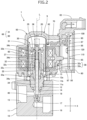
Fig. 2] Fig. 2 is a sectional view of the electric valve device. - [
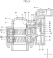
Fig. 3] Fig. 3 is a sectional view of a stator unit. - [
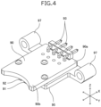
Fig. 4] Fig. 4 is a perspective view of a sensor circuit board and a circuit-board supporting member. - [
Fig. 5] Fig. 5 is another perspective view of the sensor circuit board and the circuit-board supporting member. - [
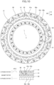
Fig. 6] Fig. 6 is a diagram illustrating an arrangement of first and second magnetic sensors. - [
Fig. 7] Fig. 7 is a diagram schematically illustrating a positional relationship between pole teeth of a stator and the first and second magnetic sensors. - [
Fig. 8] Fig. 8 is a perspective view of a control circuit board. - [
Fig. 9] Fig. 9 is a diagram illustrating a microcomputer, a stepping motor, and the first and second magnetic sensors. - [
Fig. 10] Fig. 10 is a diagram schematically illustrating a positional relationship between a magnet rotor and the stator (when pulse P[1] is input). - [
Fig. 11] Fig. 11 is a diagram schematically illustrating the positional relationship between the magnet rotor and the stator (when pulse P[2] is input). - [
Fig. 12] Fig. 12 is a diagram schematically illustrating the positional relationship between the magnet rotor and the stator (when pulse P[3] is input). - [
Fig. 13] Fig. 13 is a diagram schematically illustrating the positional relationship between the magnet rotor and the stator (when pulse P[4] is input). - [
Fig. 14] Fig. 14 is a diagram schematically illustrating the positional relationship between the magnet rotor and the stator (when pulse P[5] is input). - [
Fig. 15] Fig. 15 is a diagram schematically illustrating the positional relationship between the magnet rotor and the stator (when pulse P[6] is input). - [
Fig. 16] Fig. 16 is a diagram schematically illustrating the positional relationship between the magnet rotor and the stator (when pulse P[7] is input). - [
Fig. 17] Fig. 17 is a diagram schematically illustrating the positional relationship between the magnet rotor and the stator (when pulse P[8] is input). - [
Fig. 18] Fig. 18 is a diagram illustrating an example of output-signal expected value information of the first and second magnetic sensors. - [
Fig. 19] Fig. 19 is a diagram illustrating an example of the output-signal expected value information of the first and second magnetic sensors and output signals of the first and second magnetic sensors. - [
Fig. 20] Fig. 20 is a diagram illustrating movement of the magnet rotor in a state where rotation of the magnet rotor in a valve closing direction is restricted. - [
Fig. 21] Fig. 21 is a diagram illustrating the movement of the magnet rotor in the state where the rotation of the magnet rotor in the valve closing direction is restricted (following the diagram inFig. 20 ). - [
Fig. 22] Fig. 22 is a flowchart illustrating an example of a process of the electric valve control device. Description of Embodiments - An electric valve device according to an embodiment of the present invention is described below with reference to figures.
-
Fig.1 is a block diagram of an air conditioner system including the electric valve device according to the embodiment of the present invention.Fig. 2 is a sectional view of the electric valve device including an electric valve and an electric valve control device.Fig. 3 is a sectional view of a stator unit of the electric valve.Figs. 4 and5 are perspective views of a sensor circuit board and a circuit-board supporting member that are included in the electric valve.Fig. 6 is a diagram illustrating an arrangement of first and second magnetic sensors of the electric valve.Fig. 6 shows a can, a magnet rotor, a stator, the sensor circuit board, and the first and second magnetic sensors viewed from above. InFig. 6 , the can and the magnet rotor are illustrated in sections cut along a plane that includes an upper surface of the stator, and the sensor circuit board and the first and second magnetic sensors are represented in dashed lines. InFig. 6 , hatched areas schematically represent north poles of the magnet rotor, and dotted areas schematically represent south poles of the magnet rotor.Fig. 7 is a diagram schematically illustrating a positional relationship between pole teeth of the stator and the first and second magnetic sensors that are included in the electric valve.Fig. 8 is a perspective view of a control circuit board of the electric valve control device.Fig. 9 is a diagram illustrating a microcomputer, a stepping motor, and the first and second magnetic sensors.Fig. 9A schematically illustrates a connection relationship between the microcomputer, the stepping motor, and the first and second magnetic sensors.Fig. 9B illustrates an example of pulses input to the stepping motor. InFigs. 2 to 6 and8 , an X direction indicated by arrow X represents a left-and-right direction, a Y direction indicated by arrow Y represents a front-and-back direction, and a Z direction indicated by arrow Z represents an up-and-down direction. The direction denoted by "X" on arrow X is a right direction, the direction denoted by "Y" on arrow Y is a front direction, and the direction denoted by "Z" on arrow Z is an upward direction. - An
electric valve device 1 according to the embodiment includes anelectric valve 5 and the electric valve control device. The electric valve control device is simply referred to as "acontrol device 100". - For example, the
electric valve device 1 is installed in anair conditioner system 400 illustrated inFig. 1 . Theair conditioner system 400 includes acompressor 401, acondenser 402, the electric valve device 1 (the electric valve 5), and anevaporator 403, which are connected in this order by apipe 405. Theair conditioner system 400 includes an airconditioner control device 410. The airconditioner control device 410 is connected to the electric valve device 1 (the control device 100) via acommunication bus 420 and is able to communicate with theelectric valve device 1. The airconditioner control device 410 utilizes theelectric valve device 1 to control the flow rate of refrigerant flowing through thepipe 405. - As illustrated in
Figs. 2 to 5 , theelectric valve 5 includes avalve body 10, acan 20, adriving mechanism 30, avalve member 40, astator unit 50, asensor circuit board 90, a firstmagnetic sensor 91, and a secondmagnetic sensor 92. - The
valve body 10 is, for example, made of a metal, such as an aluminum alloy. Thevalve body 10 includes abody member 11, a supportingmember 12, and aconnection member 13. Thebody member 11 has a rectangular parallelepiped shape. Thebody member 11 has a mountinghole 11a. The mountinghole 11a is provided in anupper surface 11b of thebody member 11. The supportingmember 12 has a circular cylindrical shape. The lower part of the supportingmember 12 is disposed in the mountinghole 11a. The supportingmember 12 is mounted on thebody member 11 by a screw structure. The upper part of the supportingmember 12 projects from theupper surface 11b of thebody member 11. Thebody member 11 has avalve chamber 14,flow channels valve port 17, and avalve seat 18. Theflow channel 15 is connected to thevalve chamber 14. Theflow channel 16 is connected to thevalve chamber 14 through thevalve port 17. Thevalve seat 18 encloses thevalve port 17 in thevalve chamber 14. Theconnection member 13 has a circular annular plate-like shape. The upper part of the supportingmember 12 is bonded to the inner peripheral edge of theconnection member 13. - The
can 20 is, for example, made of a metal, such as stainless steel. Thecan 20 has a circular cylindrical shape. Thecan 20 is closed at the upper end and is open at the lower end. The lower end of thecan 20 is bonded to the outer peripheral edge of theconnection member 13. - The
driving mechanism 30 moves thevalve member 40 in the up-and-down direction (a direction of an axis L). Thedriving mechanism 30 includes amagnet rotor 31, avalve stem holder 32, aguide bush 33, and avalve stem 34. - The
magnet rotor 31 has a circular cylindrical shape. The outer diameter of themagnet rotor 31 is slightly smaller than the inner diameter of thecan 20. Themagnet rotor 31 includes magnetic poles (north (N) poles and south (S) poles). The N poles and the S poles are disposed on the outer circumferential surface of themagnet rotor 31. The N poles and the S poles extend in the up-and-down direction. The N poles and the S poles are alternately arranged at regular intervals in the circumferential direction. In the embodiment, themagnet rotor 31 has twelve N poles and twelve S poles, and the total number of the magnetic poles is 24. The interval (the angle) between the N pole and the S pole adjacent to each other is 15 degrees. - The
valve stem holder 32 has a circular cylindrical shape. Thevalve stem holder 32 is closed at the upper end and is open at the lower end. A supportingring 35 is secured to the upper part of thevalve stem holder 32. Thevalve stem holder 32 is coupled to themagnet rotor 31 via the supportingring 35. Thevalve stem holder 32 rotates together with themagnet rotor 31. The inner circumferential surface of thevalve stem holder 32 has aninternal thread 32c. - The
guide bush 33 integrally includes a first circularcylindrical portion 33a and a second circularcylindrical portion 33b. The outer diameter of the second circularcylindrical portion 33b is smaller than that of the first circularcylindrical portion 33a. The second circularcylindrical portion 33b is coaxially connected to the upper end of the first circularcylindrical portion 33a. The outer circumferential surface of the second circularcylindrical portion 33b has anexternal thread 33c. Theexternal thread 33c is screwed into theinternal thread 32c of thevalve stem holder 32. The first circularcylindrical portion 33a is press-fitted into afitting hole 12a provided in the supportingmember 12 of thevalve body 10. Theguide bush 33 is joined to thevalve body 10. - A
movable stopper 32s is secured to thevalve stem holder 32. A fixedstopper 33s is secured to the first circularcylindrical portion 33a of theguide bush 33. When themovable stopper 32s comes into contact with the fixedstopper 33s, rotation of the valve stem holder 32 (i.e., the magnet rotor 31) in a valve closing direction is restricted. Themovable stopper 32s and the fixedstopper 33s are members of astopper mechanism 38. Thestopper mechanism 38 restricts rotation of themagnet rotor 31 in the valve closing direction. - The valve stem 34 integrally includes a
first part 34a and asecond part 34b. Thefirst part 34a and thesecond part 34b each have a circular columnar shape. The diameter of thesecond part 34b is smaller than that of thefirst part 34a. Thesecond part 34b is coaxially connected to the upper end of thefirst part 34a. Thesecond part 34b extends through thevalve stem holder 32. Apush nut 36 as a retainer is mounted on thesecond part 34b. The valve stem 34 is disposed inside both theguide bush 33 and the supportingmember 12. The lower end of thefirst part 34a is disposed in thevalve chamber 14. The valve stem 34 has astep portion 34d. Thestep portion 34d is disposed in the part where thesecond part 34b is connected to thefirst part 34a. Avalve closing spring 37 is disposed between thestep portion 34d and thevalve stem holder 32. Thevalve closing spring 37 is a compression coil spring. Thevalve closing spring 37 pushes thevalve stem 34 downward. - The
valve member 40 is disposed in thevalve chamber 14. Thevalve member 40 faces thevalve port 17 in the up-and-down direction. Thevalve member 40 opens and closes thevalve port 17. Thevalve member 40 is connected to the lower end of thevalve stem 34. For example, thevalve stem 34 and thevalve member 40 are integrally formed by cutting a workpiece with a circular columnar shape. - The
stator unit 50 includes astator 60, ahousing 70, and acase 80. - The
stator 60 has a circular cylindrical shape. Thestator 60 includes anA-phase stator 61 and a B-phase stator 62. - The
A-phase stator 61 includes a plurality of claw-poletype pole teeth pole teeth 61a point downward, and the tip ends of thepole teeth 61b point upward. Thepole teeth 61a and thepole teeth 61b are alternately arranged at regular intervals in the circumferential direction. In the embodiment, theA-phase stator 61 includes twelvepole teeth 61a and twelvepole teeth 61b. The angle between thepole tooth 61a and thepole tooth 61b adjacent to each other is 15 degrees. When acoil 61c of theA-phase stator 61 is energized, thepole teeth 61a and thepole teeth 61b have opposite polarities. - The B-
phase stator 62 includes a plurality of claw-poletype pole teeth pole teeth 62a point downward, and the tip ends of thepole teeth 62b point upward. Thepole teeth 62a and thepole teeth 62b are alternately arranged at regular intervals in the circumferential direction. In the embodiment, the B-phase stator 62 includes twelvepole teeth 62a and twelvepole teeth 62b. The angle between thepole tooth 62a and thepole tooth 62b adjacent to each other is 15 degrees. When acoil 62c of the B-phase stator 62 is energized, thepole teeth 62a and thepole teeth 62b have opposite polarities. - The
A-phase stator 61 is disposed coaxially with the B-phase stator 62. TheA-phase stator 61 is in contact with the B-phase stator 62. When viewed in the direction of the axis L, the angle between thepole tooth 61a of theA-phase stator 61 and thepole tooth 62a of the B-phase stator 62 adjacent to each other is 7.5 degrees. Thecoil 61c of theA-phase stator 61 and thecoil 62c of the B-phase stator 62 are connected toterminals 65. - The
housing 70 is made of synthetic resin. Thehousing 70 has a circular cylindrical shape. Thehousing 70 is formed by injection molding. Thehousing 70 houses thestator 60. Thehousing 70 is formed by integrally molding (insert molding) with thestator 60. Thestator 60 and thehousing 70 may be manufactured separately, and thestator 60 may be fitted into thehousing 70. Thecan 20 is disposed in aninner space 74 that is defined by the inner surface of thehousing 70 and the inner circumferential surface of thestator 60. Thestator 60 and themagnet rotor 31 are members of a steppingmotor 66. - The
housing 70 has acircuit board space 75. Thecircuit board space 75 extends in a lateral direction (a direction perpendicular to the axis L). Thecircuit board space 75 is situated adjacent to theinner space 74. Apartition wall 76 is placed between theinner space 74 and thecircuit board space 75. Thepartition wall 76 separates thecircuit board space 75 from theinner space 74. The cross section (a section perpendicular to the axis L) of thepartition wall 76 has an arc shape along with the outer circumferential surface of thecan 20. - The
case 80 is made of synthetic resin. Thecase 80 has a rectangular parallelepiped box shape. Thecase 80 is bonded to thehousing 70. Aspace 85 is provided inside thecase 80 and is connected to thecircuit board space 75 through anopening 80a. Aconnector 83 is provided in the upper part of thecase 80. -
Figs. 4 and5 illustrate thesensor circuit board 90. Thesensor circuit board 90 is a printed circuit board on which electronic components are mounted. Thesensor circuit board 90 is housed in thecircuit board space 75. Thesensor circuit board 90 is positioned in the lateral direction. Afirst end 90a of thesensor circuit board 90 is disposed in thespace 85 of thecase 80. Asecond end 90b of thesensor circuit board 90 is disposed near thepartition wall 76. A circuit-board supporting member 95 is mounted on thesensor circuit board 90. The circuit-board supporting member 95 includes circularcylindrical portions 97 in whichbosses 87 of thecase 80 are disposed, and thesensor circuit board 90 is mounted on thebosses 87 via the circuit-board supporting member 95. The firstmagnetic sensor 91 and the secondmagnetic sensor 92 are mounted on thesensor circuit board 90. - The first
magnetic sensor 91 and the secondmagnetic sensor 92 are Hall-ICs. Output signals K (K1 and K2) of the firstmagnetic sensor 91 and the secondmagnetic sensor 92 are each a binary signal. The firstmagnetic sensor 91 and the secondmagnetic sensor 92 are disposed in thesecond end 90b of thesensor circuit board 90. The firstmagnetic sensor 91 and the secondmagnetic sensor 92 are positioned at equal distances from the axis L and arranged around the axis L with a gap between them. - The first
magnetic sensor 91 and the secondmagnetic sensor 92 are each radially positioned relative to themagnet rotor 31 with thecan 20 and thepartition wall 76 in between. In other words, the firstmagnetic sensor 91 and the secondmagnetic sensor 92 each radially (laterally) face themagnet rotor 31 with thecan 20 and thepartition wall 76 in between. -
Fig. 6 illustrates an example of an arrangement of the firstmagnetic sensor 91 and the secondmagnetic sensor 92. InFig.6 , a line M1 connects the axis L and a magnetic sensing section of the firstmagnetic sensor 91, and a line M2 connects the axis L and a magnetic sensing section of the secondmagnetic sensor 92. The lines M1 and M2 intersect the axis L at right angles. Where n represents the number of the magnetic poles of themagnet rotor 31, N represents a natural number, and θ represents an angle, as viewed in the direction (the direction of the axis L) of the axis of themagnet rotor 31, between the lines M1 and M2, the following expression (1) is satisfied.
- In the embodiment, n = 24, N = 1, and θ = 22.5 degrees.

- An acceptable alternative is n = 24, N = 3, and θ = 52.5 degrees.

- Another acceptable alternative is n = 24, N = 6, and θ = 97.5 degrees.

- Yet another acceptable alternative is n = 30, N = 2, and θ = 30 degrees.

- In a configuration in which the expression (1) is satisfied, when the first
magnetic sensor 91 radially faces one of the magnetic poles (the N and S poles) of themagnet rotor 31, the secondmagnetic sensor 92 radially faces a portion of the outer circumferential surface between the N pole and the S pole of themagnet rotor 31. Alternatively, when the secondmagnetic sensor 92 radially faces one of the magnetic poles (the N and S poles) of themagnet rotor 31, the firstmagnetic sensor 91 radially faces a portion of the outer circumferential surface between the N pole and the S pole of themagnet rotor 31. In a configuration in which the firstmagnetic sensor 91 and the secondmagnetic sensor 92 are positioned so that the output signal K1 of the firstmagnetic sensor 91 and the output signal K2 of the secondmagnetic sensor 92 change at different timings, it is not necessary to satisfy the expression (1). -
Fig. 7 illustrates an example of a positional relationship between theA-phase stator 61, the B-phase stator 62, the firstmagnetic sensor 91, and the secondmagnetic sensor 92. As illustrated inFig. 7 , when theA-phase stator 61 and the B-phase stator 62 are viewed in the radial direction, the center of thepole tooth 61a of theA-phase stator 61 and the magnetic sensing section of the firstmagnetic sensor 91 are positioned on a line L1, and the center of thepole tooth 62a of the B-phase stator 62 and the magnetic sensing section of the secondmagnetic sensor 92 are positioned on a line L2. The lines L1 and L2 are parallel to the axis L. - The output signals K of the first
magnetic sensor 91 and the secondmagnetic sensor 92 correspond to the direction of the magnetic field generated by the magnetic poles of themagnet rotor 31. Specifically, the firstmagnetic sensor 91 and the secondmagnetic sensor 92 each output an L signal (a first value) when detecting the S pole and an H signal (a second value) when detecting the N pole, as the output signals K. - In the
electric valve 5, the respective central axes of the body member 11 (thevalve port 17 and the valve seat 18), the supportingmember 12, theconnection member 13, thecan 20, themagnet rotor 31, thevalve stem 34, thevalve member 40, and the stator 60 (theA-phase stator 61 and the B-phase stator 62) are aligned with the axis L. - In the
electric valve 5, when themagnet rotor 31 rotates in the valve closing direction, the screw-feed action of theinternal thread 32c of thevalve stem holder 32 and theexternal thread 33c of theguide bush 33 moves themagnet rotor 31 and thevalve stem holder 32 downward. Thevalve stem holder 32 pushes thevalve stem 34 downward via thevalve closing spring 37. Thevalve stem 34 and thevalve member 40 move downward, and thevalve member 40 comes into contact with thevalve seat 18. At this time, themagnet rotor 31 is at a valve closing position Rc. When themagnet rotor 31 at this position further rotates in the valve closing direction, thevalve closing spring 37 is compressed, and themagnet rotor 31 and thevalve stem holder 32 further move downward. Thevalve member 40 does not move downward. When themovable stopper 32s comes into contact with the fixedstopper 33s, the rotation of themagnet rotor 31 in the valve closing direction is restricted. At this time, themagnet rotor 31 is at a reference position Rx. - In the
electric valve 5, when themagnet rotor 31 rotates in a valve opening direction, the screw-feed action of theinternal thread 32c of thevalve stem holder 32 and theexternal thread 33c of theguide bush 33 moves themagnet rotor 31 and thevalve stem holder 32 upward. Thevalve stem holder 32 pushes thepush nut 36 upward. Thevalve stem 34 and thevalve member 40 move upward, and thevalve member 40 moves away from thevalve seat 18. When themagnet rotor 31 further rotates in the valve opening direction, themagnet rotor 31 reaches a full-open position Rz. When themagnet rotor 31 is at the full-open position Rz, thevalve member 40 is positioned farthest from thevalve port 17. - The
control device 100 includes acontrol circuit board 110 and amicrocomputer 120. -
Fig. 8 illustrates thecontrol circuit board 110. Thecontrol circuit board 110 is a printed circuit board on which electronic components are mounted. Thecontrol circuit board 110 is housed in thespace 85 of thecase 80. Thecontrol circuit board 110 is positioned in the up-and-down direction. Thecontrol circuit board 110 is at a right angle to thesensor circuit board 90. Thecontrol circuit board 110 is disposed near thefirst end 90a of thesensor circuit board 90. Thecontrol circuit board 110 is connected to thesensor circuit board 90 via connectingterminals 93. Theterminals 65 of thestator 60 are connected to thecontrol circuit board 110. Thebosses 87 of thecase 80 are disposed in throughholes 112 of thecontrol circuit board 110, and thecontrol circuit board 110 is mounted on thebosses 87. Themicrocomputer 120 is mounted on thecontrol circuit board 110. - As illustrated in
Figs. 1 and9A , themicrocomputer 120 is, for example, a microcomputer for embedded device in which a central processing unit (a CPU 121), anon-volatile memory 122, amotor driver 123, a workingmemory 124, acommunication module 125, and the like are integrated into one package. Themicrocomputer 120 controls theelectric valve 5. A non-volatile memory, a working memory, a communication module, and a motor driver may be separate electronic components that are externally connected to themicrocomputer 120. - The
CPU 121 executes a program stored in thenon-volatile memory 122 to function as various function units. The workingmemory 124 stores variables used by the various function units. Thecommunication module 125 is connected to the airconditioner control device 410 via thecommunication bus 420. Themotor driver 123 is connected to the steppingmotor 66. Specifically, as illustrated inFig. 9A , themotor driver 123 is connected to thecoil 61c of theA-phase stator 61 and thecoil 62c of the B-phase stator 62. Themotor driver 123 supplies driving currents corresponding to pulses P to thecoils - The
magnet rotor 31 is rotated by pulses P (pulses P[1] to P[8]) input to the steppingmotor 66. Specifically, themagnet rotor 31 is rotated by the driving currents, corresponding to pulses P, supplied to thestator 60 of the steppingmotor 66. In this specification, "inputting pulses P to the steppingmotor 66" is synonymous with "supplying driving currents corresponding to pulses P to thestator 60 of the steppingmotor 66". Pulses P are repeatedly input to the steppingmotor 66 in ascending or descending order. In other words, pulses P[1] to P[8] are pulses P for one cycle and are multiple pulses P repeatedly input to the steppingmotor 66 in a predetermined order. - In the embodiment, the excitation mode of the stepping
motor 66 is 1-2-phase excitation. The step angle of the steppingmotor 66 is 3.75 degrees. When themagnet rotor 31 is at the reference position Rx, themovable stopper 32s is in contact with the fixedstopper 33s, thereby restricting the rotation of themagnet rotor 31 in the valve closing direction. The number (an initialization number) of pulses to rotate themagnet rotor 31 from the reference position Rx to the full-open position Rz is 500. - Pulses P[1] to P[8] illustrated in
Fig. 9B are input to the steppingmotor 66 in order.Figs. 10 to 17 schematically illustrate examples of a positional relationship between themagnet rotor 31 and thestator 60 when pulses P[1] to P[8] are input.Figs. 10 to 17 schematically illustrate the magnetic poles of themagnet rotor 31 and the pole teeth of thestator 60. The radially outward direction in upper diagrams ofFigs. 10 to 17 corresponds to the upward direction, and the radially inward direction corresponds to a downward direction. InFigs. 10 to 17 , thereference pole tooth 61a and the reference magnetic pole (the S pole) of themagnet rotor 31 are marked with a dot for easy understanding of the positional relationship between themagnet rotor 31 and the stator 60 (theA-phase stator 61 and the B-phase stator 62). - When pulses P are input to the stepping
motor 66 in ascending order (in the order from P[1] to P[8]), themagnet rotor 31 rotates in the valve closing direction (clockwise inFigs. 10 to 17 ). When pulses P are input to the steppingmotor 66 in descending order (in the order from P[8] to P[1]), themagnet rotor 31 rotates in the valve opening direction (counterclockwise inFigs. 10 to 17 ). -
Fig. 18 illustrates an example of output-signal expected value information J (J1 and J2) of the firstmagnetic sensor 91 and the secondmagnetic sensor 92. The output-signal expected value information J serves as expected values of the output signals K of the firstmagnetic sensor 91 and the secondmagnetic sensor 92 when pulses P[1] to P[8] are input to the steppingmotor 66. The output-signal expected value information J is stored in thenon-volatile memory 122. InFig. 18 , 'L' indicates the L signal, 'H' indicates the H signal, and '*' indicates that either 'L' or 'H' (any value) is acceptable. In theelectric valve 5, due to factors such as tolerance, either 'L' or 'H' is output at a timing corresponding to '*'. The output-signal expected value information J1 of the firstmagnetic sensor 91 is illustrated in the upper part ofFig. 18 . The output-signal expected value information J2 of the secondmagnetic sensor 92 is illustrated in the lower part ofFig. 18 . - The expected values of the output signals K of the first
magnetic sensor 91 and the secondmagnetic sensor 92 when pulse P[1] is input to the steppingmotor 66 are 'L' and '*'. - The expected values of the output signals K of the first
magnetic sensor 91 and the secondmagnetic sensor 92 when pulse P[2] is input to the steppingmotor 66 are 'L' and 'L'. - The expected values of the output signals K of the first
magnetic sensor 91 and the secondmagnetic sensor 92 when pulse P[3] is input to the steppingmotor 66 are '*' and 'L'. - The expected values of the output signals K of the first
magnetic sensor 91 and the secondmagnetic sensor 92 when pulse P[4] is input to the steppingmotor 66 are 'H' and 'L'. - The expected values of the output signals K of the first
magnetic sensor 91 and the secondmagnetic sensor 92 when pulse P[5] is input to the steppingmotor 66 are 'H' and '*'. - The expected values of the output signals K of the first
magnetic sensor 91 and the secondmagnetic sensor 92 when pulse P[6] is input to the steppingmotor 66 are 'H' and 'H'. - The expected values of the output signals K of the first
magnetic sensor 91 and the secondmagnetic sensor 92 when pulse P[7] is input to the steppingmotor 66 are '*' and 'H'. - The expected values of the output signals K of the first
magnetic sensor 91 and the secondmagnetic sensor 92 when pulse P[8] is input to the steppingmotor 66 are 'L' and 'H'. - In the embodiment, when the
magnet rotor 31 rotates in the valve closing direction, the firstmagnetic sensor 91 outputs "LLHHHHLL" as the output signal K1, and the secondmagnetic sensor 92 outputs "LLLLHHHH" as the output signal K2, in correspondence with pulses P[1] to P[8] being input. When themagnet rotor 31 rotates in the valve opening direction, the firstmagnetic sensor 91 outputs "LLHHHHLL", and the secondmagnetic sensor 92 outputs "HHHHLLLL", in correspondence with pulses P[8] to P[1] being input. The output signals K1 and K2 change according to the rotation of themagnet rotor 31. Consequently, thecontrol device 100 can detect the position and the rotation direction of themagnet rotor 31 using the output signals K1 and K2. The position of themagnet rotor 31 corresponds to, for example, the rotation angle of themagnet rotor 31 from the reference position Rx. - When the output signals K of the first
magnetic sensor 91 and the secondmagnetic sensor 92 match the output-signal expected value information J, themagnet rotor 31 is rotating. When at least one of the output signals K of the firstmagnetic sensor 91 and the secondmagnetic sensor 92 does not match the output-signal expected value information J, themagnet rotor 31 is not rotating. - The output signals K of the first
magnetic sensor 91 and the secondmagnetic sensor 92 when themagnet rotor 31 rotates in the valve closing direction in theelectric valve device 1 are described below with reference toFigs. 19 to 21 .Fig. 19 is a diagram illustrating an example of the output-signal expected value information J and the output signals K at times T1 to T409.Figs. 20 and21 are diagrams illustrating the movement of themagnet rotor 31 in a state where the rotation of themagnet rotor 31 in the valve closing direction is restricted. InFigs. 20 and21 , thereference pole tooth 61a and the reference magnetic pole (the S pole) of themagnet rotor 31 are marked with a black square for easy understanding of the positional relationship between themagnet rotor 31 and the stator 60 (theA-phase stator 61 and the B-phase stator 62). InFigs. 20 and21 , the right direction corresponds to the valve closing direction, and the left direction corresponds to the valve opening direction.Figs. 20A to 20E and21A to 21D correspond to times T401 to T409 inFig. 19 . - When the
control device 100 repeatedly inputs pulses P to the steppingmotor 66 in ascending order at regular time intervals (times T1 to T400), themagnet rotor 31 rotates in the valve closing direction by the step angle with each pulse. When thecontrol device 100 inputs pulse P[1] to the steppingmotor 66 at time T401, as illustrated inFig. 20A , themagnet rotor 31 is positioned at the reference position Rx, and themovable stopper 32s comes into contact with the fixedstopper 33s. The rotation of themagnet rotor 31 in the valve closing direction is restricted at the reference position Rx. As illustrated inFig. 19 , themagnet rotor 31 rotates in the valve closing direction after each pulse P is input from times T1 to T401, and the output signals K match the output-signal expected value information J. - When the
control device 100 inputs pulses P[2], P[3], P[4], and P[5] to the steppingmotor 66 at times T402, T403, T404, and T405, as illustrated inFigs. 20B to 20E , themagnet rotor 31 does not rotate in the valve closing direction, and the output signals K do not change. Thus, as illustrated inFig. 19 , the output signals K match the output-signal expected value information J after each pulse P is input at times T402 and T403 but do not match the output-signal expected value information J after each pulse P is input at times T404 and T405. Specifically, the output signal K1 does not match the output-signal expected value information J1. InFig. 19 , hatched areas represent some of the output signals K that do not match the output-signal expected value information J. - When the
control device 100 inputs pulse P[6] to the steppingmotor 66 at time T406, as illustrated inFig. 20A , themagnet rotor 31 rotates in the valve opening direction. The rotation angle of themagnet rotor 31 is three times the step angle. The output signals K become values corresponding to pulse P[6]. Thus, as illustrated inFig. 19 , the output signals K after pulse P is input at time T406 match the output-signal expected value information J. - When the
control device 100 inputs pulses P[7], P[8], and P[1] to the steppingmotor 66 at times T407, T408, and T409, as illustrated inFigs. 21B to 21D , themagnet rotor 31 rotates in the valve closing direction by the step angle with each pulse. Thus, as illustrated inFig. 22 , the output signals K after each pulse P is input at times T407, T408, and T409 match the output-signal expected value information J.The magnet rotor 31 is positioned at the reference position Rx again after pulse P is input at the T409, and the rotation of themagnet rotor 31 in the valve closing direction is restricted by thestopper mechanism 38. - After that, the output signals K repeatedly change in the same manner as times T401 to T408 in response to pulses P[1] to P[8] being input.
- The
control device 100 inputs pulses P to the steppingmotor 66 in ascending order, as described above. When thecontrol device 100 inputs pulses P to the steppingmotor 66 in descending order and the rotation of themagnet rotor 31 in the valve opening direction is restricted, the output signals K change in the same manner as described above. - Therefore, the
control device 100 can determine whether themagnet rotor 31 is rotating by comparing the output signals K of the firstmagnetic sensor 91 and the secondmagnetic sensor 92 obtained after each pulse P is input with the output-signal expected value information J. Thecontrol device 100 can detect that the rotation of themagnet rotor 31 is restricted, based on the determination. - An example of a process of the
control device 100 for positioning themagnet rotor 31 at the reference position Rx is described below with reference to a flowchart inFig. 22 . - The control device 100 (specifically, the CPU 121) inputs pulse P to the stepping
motor 66 in ascending order (S110). Thecontrol device 100 obtains the output signals K of the firstmagnetic sensor 91 and the second magnetic sensor 92 (S120). Thecontrol device 100 reads the output-signal expected value information J, corresponding to pulse P being input, from thenon-volatile memory 122 to compare the output signals K with the output-signal expected value information J (S130). When the output signals K match the output-signal expected value information J (Y in S130), thecontrol device 100 determines that themagnet rotor 31 is rotating and inputs next pulse P (return to S110). When the output signals K do not match the output-signal expected value information J (N in S130), thecontrol device 100 determines that themagnet rotor 31 is not rotating and detects that the rotation of themagnet rotor 31 in the valve closing direction is restricted (S140). As a result, thecontrol device 100 determines that themagnet rotor 31 is positioned at the reference position Rx and finishes the process. - The
control device 100 can detect that the rotation of themagnet rotor 31 in the valve closing direction is restricted by thestopper mechanism 38. Additionally, thecontrol device 100 can detect, for example, that the rotation of themagnet rotor 31 is restricted due to foreign matters contained in refrigerant. - In the
electric valve 5, types of rotation restriction of themagnet rotor 31 include (i) rotation restriction by thestopper mechanism 38, (ii) rotation restriction due to valve lock, and (iii) rotation restriction due to rotor lock. In type (i), when themagnet rotor 31 is at the reference position Rx, themovable stopper 32s is in contact with the fixedstopper 33s, restricting the rotation of themagnet rotor 31 in the valve closing direction. In type (ii), foreign matter lodged between thevalve port 17 and thevalve member 40 prevents thevalve member 40 from moving, restricting the rotation of themagnet rotor 31. In type (iii), foreign matter lodged between the inner circumferential surface of thecan 20 and the outer circumferential surface of themagnet rotor 31 restricts the rotation of themagnet rotor 31. - In type (i), the
magnet rotor 31 can rotate in the valve opening direction. In type (ii), themagnet rotor 31 can rotate by an angle corresponding to the play between theinternal thread 32c of thevalve stem holder 32 and theexternal thread 33c of theguide bush 33. In types (i) and (ii), when pulses P are sequentially input to rotate themagnet rotor 31 in one direction (the valve closing direction or the valve opening direction) and continue to be input even after the rotation of themagnet rotor 31 is restricted, themagnet rotor 31 repeatedly exhibits a movement in which themagnet rotor 31 temporarily rotates in the opposite direction before resuming its original rotation. This movement is referred to as "a reverse rotation movement". - In type (iii), the
magnet rotor 31 cannot rotate in any direction. In type (iii), when pulses P are sequentially input to rotate themagnet rotor 31 in one direction (the valve closing direction or the valve opening direction) and continue to be input even after the rotation of themagnet rotor 31 is restricted, themagnet rotor 31 does not rotate in any direction. - Consequently, upon detecting the rotation restriction of the
magnet rotor 31, thecontrol device 100 can determine that the rotation restriction corresponds to type (i) or (ii) when themagnet rotor 31 exhibits the reverse rotation movement and to type (iii) when themagnet rotor 31 does not exhibit the reverse rotation movement. Thecontrol device 100 may be configured to send a malfunction alert for theelectric valve 5 to the airconditioner control device 410 when the rotation restriction of themagnet rotor 31 corresponds to type (iii) and is not eliminated even though an attempt is made to rotate themagnet rotor 31 in the opposite direction. - The
electric valve device 1 according to the embodiment includes theelectric valve 5 and thecontrol device 100. Theelectric valve 5 includes thevalve body 10 that has thevalve port 17, thevalve member 40 that faces thevalve port 17, thecan 20 that is bonded to thevalve body 10, the steppingmotor 66 for moving thevalve member 40, the firstmagnetic sensor 91, and the secondmagnetic sensor 92. The steppingmotor 66 includes themagnet rotor 31 that has a circular cylindrical shape and is disposed inside thecan 20 and thestator 60 that is disposed outside thecan 20. The N poles and the S poles are alternately arranged on the outer circumferential surface of themagnet rotor 31 at regular intervals in the circumferential direction. The firstmagnetic sensor 91 and the secondmagnetic sensor 92 are disposed outside thecan 20 and are radially positioned relative to themagnet rotor 31. Where n represents the total number of the N poles and the S poles, N represents a natural number, and θ represents the angle between the line M1 connecting the axis L (the axis of the magnet rotor 31) to the firstmagnetic sensor 91 and the line M2 connecting the axis L to the secondmagnetic sensor 92, the following expression (1) is satisfied.
- The output signals K of the first
magnetic sensor 91 and the secondmagnetic sensor 92 are each a binary signal. Thecontrol device 100 detects that the rotation of themagnet rotor 31 is restricted using the output signals K and the output-signal expected value information J. - With this configuration, whether the
magnet rotor 31 is rotating can be determined by comparing the output signals K of the firstmagnetic sensor 91 and the secondmagnetic sensor 92 with the output-signal expected value information J serving as the expected values of these signals. Therefore, it can be detected in a relatively simple way that the rotation of themagnet rotor 31 is restricted, based on the determination of the rotation of themagnet rotor 31. - The
control device 100 may be configured to detect the rotation direction of themagnet rotor 31 using the output signals K of the firstmagnetic sensor 91 and the secondmagnetic sensor 92. - For example, as illustrated in
Fig. 19 , themagnet rotor 31 rotates in the valve closing direction when thecontrol device 100 inputs pulses P to the steppingmotor 66 in ascending order. The output signal K1 of the firstmagnetic sensor 91 changes from 'L' to 'H' in response to pulses P[2], P[3], and P[4] being input, and the output signal K2 of the secondmagnetic sensor 92 changes from 'L' to 'H' in response to pulses P[4], P[5], and P[6] being input. - Alternatively, the
magnet rotor 31 rotates in the valve opening direction when thecontrol device 100 inputs pulses P to the steppingmotor 66 in descending order. The output signal K2 of the secondmagnetic sensor 92 changes from 'L' to 'H' in response to pulses P[2], P[1], and P[8] being input, and the output signal K1 of the firstmagnetic sensor 91 changes from 'L' to 'H' in response to pulses P[8], P[7], and P[6] being input. - In other words, when the
magnet rotor 31 rotates in the valve closing direction, the output signal K of the firstmagnetic sensor 91 changes from 'L' to 'H', followed by the output signal K of the secondmagnetic sensor 92 changing from 'L' to 'H'. When themagnet rotor 31 rotates in the valve opening direction, the output signal K of the secondmagnetic sensor 92 changes from 'L' to 'H', followed by the output signal K of the firstmagnetic sensor 91 changing from 'L' to 'H'. - Therefore, the
control device 100 can detect, in a relatively simple way, the rotation direction of themagnet rotor 31 using timing when the output signal K of the firstmagnetic sensor 91 changes from the L signal (the first value) to the H signal (the second value) and timing when the output signal K of the secondmagnetic sensor 92 changes from the L signal (the first value) to the H signal (the second value). The L and H signals may be assigned as the second and first values, respectively. - The output signal K1 of the first
magnetic sensor 91 and the output signal K2 of the secondmagnetic sensor 92 change according to the rotation of themagnet rotor 31. Therefore, thecontrol device 100 can detect the position (the rotation angle from the reference position Rx) and the rotation direction of themagnet rotor 31 using the output signals K1 and K2. Thecontrol device 100 may detect that the rotation of themagnet rotor 31 is restricted using the position or the rotation direction of themagnet rotor 31. - In the embodiment, the
control device 100 is configured to control theelectric valve 5. However, the airconditioner control device 410 may be configured to directly control theelectric valve 5. In this configuration, the airconditioner control device 410 serves as an electric valve control device. - In this specification, the terms indicating shapes of members, such as "circular cylindrical" and "circular columnar", are also used for members substantially having the shapes indicated by the terms. For example, "circular cylindrical member" includes a circular cylindrical member and a substantially circular cylindrical member.
- The embodiment of the present invention is described above. The present invention, however, is not limited to the embodiment. Embodiments obtained by a person skilled in the art appropriately adding, removing, or modifying components according to the embodiment described above, and an embodiment obtained by appropriately combining features of the embodiment are included in the scope of the present invention without departing from the spirit of the present invention.
- 1 ... electric valve device, 5 ... electric valve, 10 ... valve body, 11 ... body member, 11a ... mounting hole, 11b ... upper surface, 12 ... supporting member, 12a ... fitting hole, 13 ... connection member, 14 ... valve chamber, 15, 16 ... flow channel, 17 ... valve port, 18 ... valve seat, 20 ... can, 30 ... driving mechanism, 31 ... magnet rotor, 32 ... valve stem holder, 32c ... internal thread, 32s ... movable stopper, 33 ... guide bush, 33a ... first circular cylindrical portion, 33b ... second circular cylindrical portion, 33c ... external thread, 33s ... fixed stopper, 34 ... valve stem, 34a ... first part, 34b ... second part, 34d ... step portion, 35 ... supporting ring, 36 ... push nut, 37 ... valve closing spring, 38 ... stopper mechanism, 40 ... valve member, 50 ... stator unit, 60 ... stator, 61 ... A-phase stator, 61a, 61b ... pole tooth, 61c ... coil, 62 ... B-phase stator, 62a, 62b ... pole tooth, 62c ... coil, 65 ... terminal, 66 ... stepping motor, 70 ... housing, 74 ... inner space, 75 ... circuit board space, 76 ... partition wall, 80 ... case, 80a ... opening, 83 ... connector, 85 ... space, 87 ... boss, 90 ... sensor circuit board, 90a ... first end, 90b ... second end, 93 ... connecting terminal, 95 ... circuit-board supporting member, 97 ... circular cylindrical portion, 91 ... first magnetic sensor, 92 ... second magnetic sensor, 100 ... electric valve control device, 110 ... control circuit board, 112 ... through hole, 120 ... microcomputer, 121 ... CPU, 122 ... non-volatile memory, 123 ... motor driver, 124 ... working memory, 125 ... communication module, L ... axis, J, J1, J2 ... output-signal expected value information, K, K1, K2 ... output signal
Claims (4)
- An electric valve control device for controlling an electric valve,wherein the electric valve includes a valve body that has a valve port, a valve member that faces the valve port, a can that is bonded to the valve body, a stepping motor for moving the valve member, and a first magnetic sensor and a second magnetic sensor that are disposed outside the can,wherein the stepping motor includes a magnet rotor that has a circular cylindrical shape and is disposed inside the can and a stator that is disposed outside the can,wherein north poles and south poles are alternately arranged on an outer circumferential surface of the magnet rotor at regular intervals in a circumferential direction,wherein where n represents a total number of the north poles and the south poles, N represents a natural number, and θ represents an angle, as viewed in a direction of an axis of the magnet rotor, between a line connecting the axis to the first magnetic sensor and a line connecting the axis to the second magnetic sensor, a following expression (1) is satisfied,
 wherein an output signal of the first magnetic sensor and an output signal of the second magnetic sensor are each a binary signal, andwherein the electric valve control device is configured to detect that rotation of the magnet rotor is restricted using the output signal of the first magnetic sensor and the output signal of the second magnetic sensor and output-signal expected value information that serves as expected values of the output signal of the first magnetic sensor and the output signal of the second magnetic sensor while the magnet rotor rotates.
 - The electric valve control device according to Claim 1,
wherein the electric valve control device is configured to detect rotation direction of the magnet rotor using timing when the output signal of the first magnetic sensor changes from a first value to a second value and timing when the output signal of the second magnetic sensor changes from the first value to the second value. - An electric valve control device for controlling an electric valve,wherein the electric valve includes a valve body that has a valve port, a valve member that faces the valve port, a can that is bonded to the valve body, a stepping motor for moving the valve member, and a first magnetic sensor and a second magnetic sensor that are disposed outside the can,wherein the stepping motor includes a magnet rotor that has a circular cylindrical shape and is disposed inside the can and a stator that is disposed outside the can,wherein north poles and south poles are alternately arranged on an outer circumferential surface of the magnet rotor at regular intervals in a circumferential direction, andwherein the electric valve control device is configured to detect position and rotation direction of the magnet rotor using an output signal of the first magnetic sensor and an output signal of the second magnetic sensor.
- An electric valve device comprising: the electric valve; and the electric valve control device according to any one of Claims 1 to 3.
Applications Claiming Priority (2)
| Application Number | Priority Date | Filing Date | Title |
|---|---|---|---|
| JP2022093270A JP7546940B2 (en) | 2022-06-08 | 2022-06-08 | Motor-operated valve control device and motor-operated valve device |
| PCT/JP2023/018927 WO2023238645A1 (en) | 2022-06-08 | 2023-05-22 | Electric valve control device and electric valve device |
Publications (2)
| Publication Number | Publication Date |
|---|---|
| EP4538571A1 true EP4538571A1 (en) | 2025-04-16 |
| EP4538571A4 EP4538571A4 (en) | 2026-05-20 |
Family
ID=89118281
Family Applications (1)
| Application Number | Title | Priority Date | Filing Date |
|---|---|---|---|
| EP23819629.9A Pending EP4538571A4 (en) | 2022-06-08 | 2023-05-22 | ELECTRIC VALVE CONTROL DEVICE AND ELECTRIC VALVE DEVICE |
Country Status (4)
| Country | Link |
|---|---|
| EP (1) | EP4538571A4 (en) |
| JP (1) | JP7546940B2 (en) |
| CN (1) | CN119234104A (en) |
| WO (1) | WO2023238645A1 (en) |
Families Citing this family (2)
| Publication number | Priority date | Publication date | Assignee | Title |
|---|---|---|---|---|
| WO2025177602A1 (en) * | 2024-02-21 | 2025-08-28 | 株式会社不二工機 | Electric valve control device, electric valve device, and electric valve control method |
| WO2025177601A1 (en) * | 2024-02-21 | 2025-08-28 | 株式会社不二工機 | Electric valve control device, electric valve device, and control method for electric valve |
Family Cites Families (5)
| Publication number | Priority date | Publication date | Assignee | Title |
|---|---|---|---|---|
| JPH08326952A (en) * | 1995-06-05 | 1996-12-10 | Nippondenso Co Ltd | Operation failure diagnosis device for flow rate control valve |
| JP4335364B2 (en) * | 1999-06-29 | 2009-09-30 | 株式会社不二工機 | Electric valve opening degree detection device and electric valve opening degree control device |
| JP4028291B2 (en) * | 2002-05-16 | 2007-12-26 | 株式会社鷺宮製作所 | Motorized valve drive device and refrigeration cycle device |
| JP7272656B2 (en) * | 2020-01-10 | 2023-05-12 | 株式会社不二工機 | electric valve |
| JP7168232B2 (en) * | 2020-01-14 | 2022-11-09 | 株式会社不二工機 | electric valve |
-
2022
- 2022-06-08 JP JP2022093270A patent/JP7546940B2/en active Active
-
2023
- 2023-05-22 EP EP23819629.9A patent/EP4538571A4/en active Pending
- 2023-05-22 WO PCT/JP2023/018927 patent/WO2023238645A1/en not_active Ceased
- 2023-05-22 CN CN202380014622.7A patent/CN119234104A/en active Pending
Also Published As
| Publication number | Publication date |
|---|---|
| JP7546940B2 (en) | 2024-09-09 |
| EP4538571A4 (en) | 2026-05-20 |
| CN119234104A (en) | 2024-12-31 |
| KR20240093905A (en) | 2024-06-24 |
| WO2023238645A1 (en) | 2023-12-14 |
| JP2023180134A (en) | 2023-12-20 |
Similar Documents
| Publication | Publication Date | Title |
|---|---|---|
| US10982792B2 (en) | Electric valve | |
| CN114901977B (en) | Electric valve | |
| US12234923B2 (en) | Electric valve | |
| EP4089306A1 (en) | Electric-operated valve | |
| CN119234104A (en) | Electric valve control device and electric valve device | |
| US20250198534A1 (en) | Electric valve and method for obtaining valve-member position of electric valve | |
| EP4435303A1 (en) | Electric valve control device and electric valve device | |
| EP4177544B1 (en) | Electric-operated valve, method of controlling the same, and method of manufacturing the same | |
| KR102963801B1 (en) | Electric valve control device and electric valve device | |
| EP4474687A1 (en) | Motorized valve control device and motorized valve device | |
| WO2024127739A1 (en) | Electric valve and electric valve device | |
| EP4215781A1 (en) | Electric-operated valve | |
| US12595863B2 (en) | Electric valve | |
| EP4545830A1 (en) | Motorized valve control device and motorized valve device | |
| JP7669043B2 (en) | Motor-operated valve, motor-operated valve device, and method for assembling the motor-operated valve device | |
| JP2023031233A (en) | Motor-operated valve, control method thereof and manufacturing method thereof | |
| EP4435304A1 (en) | Electric valve | |
| KR102963780B1 (en) | Electric valve control device and electric valve device | |
| CN118076822A (en) | Electric valve control device and electric valve device |
Legal Events
| Date | Code | Title | Description |
|---|---|---|---|
| STAA | Information on the status of an ep patent application or granted ep patent |
Free format text: STATUS: THE INTERNATIONAL PUBLICATION HAS BEEN MADE |
|
| PUAI | Public reference made under article 153(3) epc to a published international application that has entered the european phase |
Free format text: ORIGINAL CODE: 0009012 |
|
| STAA | Information on the status of an ep patent application or granted ep patent |
Free format text: STATUS: REQUEST FOR EXAMINATION WAS MADE |
|
| 17P | Request for examination filed |
Effective date: 20241106 |
|
| AK | Designated contracting states |
Kind code of ref document: A1 Designated state(s): AL AT BE BG CH CY CZ DE DK EE ES FI FR GB GR HR HU IE IS IT LI LT LU LV MC ME MK MT NL NO PL PT RO RS SE SI SK SM TR |
|
| DAV | Request for validation of the european patent (deleted) | ||
| DAX | Request for extension of the european patent (deleted) |