EP4538551A1 - Sliding component - Google Patents
Sliding component Download PDFInfo
- Publication number
- EP4538551A1 EP4538551A1 EP23819863.4A EP23819863A EP4538551A1 EP 4538551 A1 EP4538551 A1 EP 4538551A1 EP 23819863 A EP23819863 A EP 23819863A EP 4538551 A1 EP4538551 A1 EP 4538551A1
- Authority
- EP
- European Patent Office
- Prior art keywords
- recessed strip
- recessed
- sliding
- dimple
- sliding component
- Prior art date
- Legal status (The legal status is an assumption and is not a legal conclusion. Google has not performed a legal analysis and makes no representation as to the accuracy of the status listed.)
- Pending
Links
Images



Classifications
-
- F—MECHANICAL ENGINEERING; LIGHTING; HEATING; WEAPONS; BLASTING
- F16—ENGINEERING ELEMENTS AND UNITS; GENERAL MEASURES FOR PRODUCING AND MAINTAINING EFFECTIVE FUNCTIONING OF MACHINES OR INSTALLATIONS; THERMAL INSULATION IN GENERAL
- F16C—SHAFTS; FLEXIBLE SHAFTS; ELEMENTS OR CRANKSHAFT MECHANISMS; ROTARY BODIES OTHER THAN GEARING ELEMENTS; BEARINGS
- F16C17/00—Sliding-contact bearings for exclusively rotary movement
- F16C17/04—Sliding-contact bearings for exclusively rotary movement for axial load only
-
- F—MECHANICAL ENGINEERING; LIGHTING; HEATING; WEAPONS; BLASTING
- F16—ENGINEERING ELEMENTS AND UNITS; GENERAL MEASURES FOR PRODUCING AND MAINTAINING EFFECTIVE FUNCTIONING OF MACHINES OR INSTALLATIONS; THERMAL INSULATION IN GENERAL
- F16J—PISTONS; CYLINDERS; SEALINGS
- F16J15/00—Sealings
- F16J15/16—Sealings between relatively-moving surfaces
- F16J15/34—Sealings between relatively-moving surfaces with slip-ring pressed against a more or less radial face on one member
- F16J15/3404—Sealings between relatively-moving surfaces with slip-ring pressed against a more or less radial face on one member and characterised by parts or details relating to lubrication, cooling or venting of the seal
- F16J15/3408—Sealings between relatively-moving surfaces with slip-ring pressed against a more or less radial face on one member and characterised by parts or details relating to lubrication, cooling or venting of the seal at least one ring having an uneven slipping surface
- F16J15/3412—Sealings between relatively-moving surfaces with slip-ring pressed against a more or less radial face on one member and characterised by parts or details relating to lubrication, cooling or venting of the seal at least one ring having an uneven slipping surface with cavities
- F16J15/3416—Sealings between relatively-moving surfaces with slip-ring pressed against a more or less radial face on one member and characterised by parts or details relating to lubrication, cooling or venting of the seal at least one ring having an uneven slipping surface with cavities with at least one continuous groove
-
- F—MECHANICAL ENGINEERING; LIGHTING; HEATING; WEAPONS; BLASTING
- F16—ENGINEERING ELEMENTS AND UNITS; GENERAL MEASURES FOR PRODUCING AND MAINTAINING EFFECTIVE FUNCTIONING OF MACHINES OR INSTALLATIONS; THERMAL INSULATION IN GENERAL
- F16C—SHAFTS; FLEXIBLE SHAFTS; ELEMENTS OR CRANKSHAFT MECHANISMS; ROTARY BODIES OTHER THAN GEARING ELEMENTS; BEARINGS
- F16C17/00—Sliding-contact bearings for exclusively rotary movement
- F16C17/04—Sliding-contact bearings for exclusively rotary movement for axial load only
- F16C17/045—Sliding-contact bearings for exclusively rotary movement for axial load only with grooves in the bearing surface to generate hydrodynamic pressure, e.g. spiral groove thrust bearings
-
- F—MECHANICAL ENGINEERING; LIGHTING; HEATING; WEAPONS; BLASTING
- F16—ENGINEERING ELEMENTS AND UNITS; GENERAL MEASURES FOR PRODUCING AND MAINTAINING EFFECTIVE FUNCTIONING OF MACHINES OR INSTALLATIONS; THERMAL INSULATION IN GENERAL
- F16C—SHAFTS; FLEXIBLE SHAFTS; ELEMENTS OR CRANKSHAFT MECHANISMS; ROTARY BODIES OTHER THAN GEARING ELEMENTS; BEARINGS
- F16C33/00—Parts of bearings; Special methods for making bearings or parts thereof
- F16C33/02—Parts of sliding-contact bearings
- F16C33/04—Brasses; Bushes; Linings
- F16C33/06—Sliding surface mainly made of metal
- F16C33/10—Construction relative to lubrication
- F16C33/1025—Construction relative to lubrication with liquid, e.g. oil, as lubricant
-
- F—MECHANICAL ENGINEERING; LIGHTING; HEATING; WEAPONS; BLASTING
- F16—ENGINEERING ELEMENTS AND UNITS; GENERAL MEASURES FOR PRODUCING AND MAINTAINING EFFECTIVE FUNCTIONING OF MACHINES OR INSTALLATIONS; THERMAL INSULATION IN GENERAL
- F16C—SHAFTS; FLEXIBLE SHAFTS; ELEMENTS OR CRANKSHAFT MECHANISMS; ROTARY BODIES OTHER THAN GEARING ELEMENTS; BEARINGS
- F16C33/00—Parts of bearings; Special methods for making bearings or parts thereof
- F16C33/02—Parts of sliding-contact bearings
- F16C33/04—Brasses; Bushes; Linings
- F16C33/06—Sliding surface mainly made of metal
- F16C33/10—Construction relative to lubrication
- F16C33/1025—Construction relative to lubrication with liquid, e.g. oil, as lubricant
- F16C33/106—Details of distribution or circulation inside the bearings, e.g. details of the bearing surfaces to affect flow or pressure of the liquid
- F16C33/1065—Grooves on a bearing surface for distributing or collecting the liquid
-
- F—MECHANICAL ENGINEERING; LIGHTING; HEATING; WEAPONS; BLASTING
- F16—ENGINEERING ELEMENTS AND UNITS; GENERAL MEASURES FOR PRODUCING AND MAINTAINING EFFECTIVE FUNCTIONING OF MACHINES OR INSTALLATIONS; THERMAL INSULATION IN GENERAL
- F16C—SHAFTS; FLEXIBLE SHAFTS; ELEMENTS OR CRANKSHAFT MECHANISMS; ROTARY BODIES OTHER THAN GEARING ELEMENTS; BEARINGS
- F16C33/00—Parts of bearings; Special methods for making bearings or parts thereof
- F16C33/02—Parts of sliding-contact bearings
- F16C33/04—Brasses; Bushes; Linings
- F16C33/06—Sliding surface mainly made of metal
- F16C33/10—Construction relative to lubrication
- F16C33/1025—Construction relative to lubrication with liquid, e.g. oil, as lubricant
- F16C33/106—Details of distribution or circulation inside the bearings, e.g. details of the bearing surfaces to affect flow or pressure of the liquid
- F16C33/107—Grooves for generating pressure
-
- F—MECHANICAL ENGINEERING; LIGHTING; HEATING; WEAPONS; BLASTING
- F16—ENGINEERING ELEMENTS AND UNITS; GENERAL MEASURES FOR PRODUCING AND MAINTAINING EFFECTIVE FUNCTIONING OF MACHINES OR INSTALLATIONS; THERMAL INSULATION IN GENERAL
- F16C—SHAFTS; FLEXIBLE SHAFTS; ELEMENTS OR CRANKSHAFT MECHANISMS; ROTARY BODIES OTHER THAN GEARING ELEMENTS; BEARINGS
- F16C33/00—Parts of bearings; Special methods for making bearings or parts thereof
- F16C33/02—Parts of sliding-contact bearings
- F16C33/04—Brasses; Bushes; Linings
- F16C33/24—Brasses; Bushes; Linings with different areas of the sliding surface consisting of different materials
-
- F—MECHANICAL ENGINEERING; LIGHTING; HEATING; WEAPONS; BLASTING
- F16—ENGINEERING ELEMENTS AND UNITS; GENERAL MEASURES FOR PRODUCING AND MAINTAINING EFFECTIVE FUNCTIONING OF MACHINES OR INSTALLATIONS; THERMAL INSULATION IN GENERAL
- F16C—SHAFTS; FLEXIBLE SHAFTS; ELEMENTS OR CRANKSHAFT MECHANISMS; ROTARY BODIES OTHER THAN GEARING ELEMENTS; BEARINGS
- F16C33/00—Parts of bearings; Special methods for making bearings or parts thereof
- F16C33/72—Sealings
- F16C33/74—Sealings of sliding-contact bearings
- F16C33/741—Sealings of sliding-contact bearings by means of a fluid
-
- F—MECHANICAL ENGINEERING; LIGHTING; HEATING; WEAPONS; BLASTING
- F16—ENGINEERING ELEMENTS AND UNITS; GENERAL MEASURES FOR PRODUCING AND MAINTAINING EFFECTIVE FUNCTIONING OF MACHINES OR INSTALLATIONS; THERMAL INSULATION IN GENERAL
- F16J—PISTONS; CYLINDERS; SEALINGS
- F16J15/00—Sealings
- F16J15/16—Sealings between relatively-moving surfaces
- F16J15/34—Sealings between relatively-moving surfaces with slip-ring pressed against a more or less radial face on one member
-
- F—MECHANICAL ENGINEERING; LIGHTING; HEATING; WEAPONS; BLASTING
- F16—ENGINEERING ELEMENTS AND UNITS; GENERAL MEASURES FOR PRODUCING AND MAINTAINING EFFECTIVE FUNCTIONING OF MACHINES OR INSTALLATIONS; THERMAL INSULATION IN GENERAL
- F16J—PISTONS; CYLINDERS; SEALINGS
- F16J15/00—Sealings
- F16J15/16—Sealings between relatively-moving surfaces
- F16J15/34—Sealings between relatively-moving surfaces with slip-ring pressed against a more or less radial face on one member
- F16J15/3404—Sealings between relatively-moving surfaces with slip-ring pressed against a more or less radial face on one member and characterised by parts or details relating to lubrication, cooling or venting of the seal
- F16J15/3408—Sealings between relatively-moving surfaces with slip-ring pressed against a more or less radial face on one member and characterised by parts or details relating to lubrication, cooling or venting of the seal at least one ring having an uneven slipping surface
- F16J15/3412—Sealings between relatively-moving surfaces with slip-ring pressed against a more or less radial face on one member and characterised by parts or details relating to lubrication, cooling or venting of the seal at least one ring having an uneven slipping surface with cavities
-
- F—MECHANICAL ENGINEERING; LIGHTING; HEATING; WEAPONS; BLASTING
- F16—ENGINEERING ELEMENTS AND UNITS; GENERAL MEASURES FOR PRODUCING AND MAINTAINING EFFECTIVE FUNCTIONING OF MACHINES OR INSTALLATIONS; THERMAL INSULATION IN GENERAL
- F16J—PISTONS; CYLINDERS; SEALINGS
- F16J15/00—Sealings
- F16J15/16—Sealings between relatively-moving surfaces
- F16J15/34—Sealings between relatively-moving surfaces with slip-ring pressed against a more or less radial face on one member
- F16J15/3404—Sealings between relatively-moving surfaces with slip-ring pressed against a more or less radial face on one member and characterised by parts or details relating to lubrication, cooling or venting of the seal
- F16J15/3408—Sealings between relatively-moving surfaces with slip-ring pressed against a more or less radial face on one member and characterised by parts or details relating to lubrication, cooling or venting of the seal at least one ring having an uneven slipping surface
- F16J15/3424—Sealings between relatively-moving surfaces with slip-ring pressed against a more or less radial face on one member and characterised by parts or details relating to lubrication, cooling or venting of the seal at least one ring having an uneven slipping surface with microcavities
-
- F—MECHANICAL ENGINEERING; LIGHTING; HEATING; WEAPONS; BLASTING
- F16—ENGINEERING ELEMENTS AND UNITS; GENERAL MEASURES FOR PRODUCING AND MAINTAINING EFFECTIVE FUNCTIONING OF MACHINES OR INSTALLATIONS; THERMAL INSULATION IN GENERAL
- F16C—SHAFTS; FLEXIBLE SHAFTS; ELEMENTS OR CRANKSHAFT MECHANISMS; ROTARY BODIES OTHER THAN GEARING ELEMENTS; BEARINGS
- F16C2240/00—Specified values or numerical ranges of parameters; Relations between them
- F16C2240/40—Linear dimensions, e.g. length, radius, thickness, gap
- F16C2240/44—Hole or pocket sizes
-
- F—MECHANICAL ENGINEERING; LIGHTING; HEATING; WEAPONS; BLASTING
- F16—ENGINEERING ELEMENTS AND UNITS; GENERAL MEASURES FOR PRODUCING AND MAINTAINING EFFECTIVE FUNCTIONING OF MACHINES OR INSTALLATIONS; THERMAL INSULATION IN GENERAL
- F16C—SHAFTS; FLEXIBLE SHAFTS; ELEMENTS OR CRANKSHAFT MECHANISMS; ROTARY BODIES OTHER THAN GEARING ELEMENTS; BEARINGS
- F16C33/00—Parts of bearings; Special methods for making bearings or parts thereof
- F16C33/02—Parts of sliding-contact bearings
- F16C33/04—Brasses; Bushes; Linings
- F16C33/043—Sliding surface consisting mainly of ceramics, cermets or hard carbon, e.g. diamond like carbon [DLC]
Definitions
- a mechanical seal as a shaft sealing device that prevents a leakage of a sealed fluid includes a pair of sliding components having an annular shape which rotate relative to each other and of which sliding surfaces slide on each other.
- a mechanical seal in recent years, there has been a desire to reduce the loss of energy due to sliding for environmental measures and the like. Therefore, for example, by allowing liquid to flow to a gap between sliding surfaces of the sliding components and forming a fluid film between the sliding surfaces, lubricity may be improved and low friction may be realized.
- a sliding surface of one sliding component of a mechanical seal includes a plurality of very small recessed strip portions provided at a predetermined pitch width, and deep groove portions provided across the plurality of recessed strip portions and deeper than the recessed strip portions.
- the severe wear is wear in which the amount of wear increases as the sliding distance increases
- the mild wear is wear in which the amount of wear hardly increases even when the sliding distance increases.
- a wear rate of the mild wear is 1/10 to 1/1000 of a wear rate of the severe wear.
- Patent Citation 1 JP 2019-108921 A (Page 5, FIG. 1 )
- the present invention has been made in view of such problems, and an object of the present invention is to provide a sliding component capable of effectively retaining fine wear products in a recessed strip portion.
- a sliding component according to the present invention is a sliding component that is disposed at a location of relative rotation of a rotating machine and that slides relative to a counterpart sliding member.
- a recessed strip portion is formed on a sliding surface of the sliding component, and the recessed strip portion is provided with a step having a difference in height, which traps a wear product.
- the sliding component is made of SiC. According to this preferable configuration, since SiC has high hydrophilicity and the surface area of the wear product is wide, water can be suitably held around the recessed strip portion or the step.
- a sliding component according to a first embodiment of the present invention will be described with reference to FIGS. 1 to 7 .
- a mode in which the sliding components form a mechanical seal will be described as an example.
- a description will be made based on the assumption that a radially outer side of the sliding components forming a mechanical seal is a sealed fluid side (high-pressure side) and a radially inner side is an atmosphere side (low-pressure side) as a leakage side.
- dots may be added to grooves and the like formed on a sliding surface.
- a width dimension L2 of the land 12 in the radial direction is slightly smaller than the width dimension L1 of the recessed strip groove 14 in the radial direction (L1 > L2).
- a mode in which the width dimension L2 of the land 12 is smaller than the width dimension L1 of the recessed strip groove 14 has been provided as an example; however, the width of the land between the recessed strip grooves may be larger than the width of the recessed strip groove, or the width of the land and the width of the recessed strip groove may be the same. From the viewpoint of forming a plateau layer 16 to be described later, it is preferable that the width dimension L1 of the land is larger than 1/3 times and smaller than 3 times the width dimension L2 of the recessed strip groove (1/3L2 ⁇ L1 ⁇ 3L2).
- the stationary seal ring 10 of the present embodiment is configured by forming the recessed strip grooves 14 on the sliding surface 11 and then forming the dimples 15 on the bottom portions 14a of the recessed strip grooves 14. Incidentally, after the dimples 15 are formed on the sliding surface 11, the recessed strip grooves 14 may be formed.
- the sealed fluid F is stored in the recessed strip groove 14.
- the stationary seal ring 10 is biased toward the rotating seal ring 20 side by the bellows 7, there is substantially no leakage from between the sliding surfaces 11 and 21 to the low-pressure side.
- the land 12 of the stationary seal ring 10 and the flat surface of the sliding surface 21 of the rotating seal ring 20 come into local contact with each other, so that the fine wear products 30 are generated.
- the top portion 12a of the land 12 is curved to protrude toward the rotating seal ring 20 side, the formation of large wear products is suppressed.
- the wear products 30 may originate from the stationary seal ring 10, may originate from the rotating seal ring 20, or may be a mixture thereof.
- the fine wear products 30 move along the recessed strip groove 14 together with the sealed fluid F. Some of the wear products 30 moving along the recessed strip groove 14 is trapped in the dimple 15. Specifically, a surface on a downstream side of the relative rotation, which forms the dimple 15, is disposed at a lower position than the bottom portion 14a of the recessed strip groove 14, and the surface traps the wear products 30.
- the wear products 30 flowing along the recessed strip groove 14 are trapped and deposited by the dimples 15 provided on the recessed strip groove 14, the fine wear products 30 serving as a lubricant can be effectively retained in the recessed strip groove 14.
- the sealed fluid F can be held in the fine gaps between the wear products 30, lubricity between the sliding surfaces 11 and 21 is improved.
- the plurality of recessed strip grooves 14 are independently provided in the radial direction. In other words, since the recessed strip grooves 14 are not in communication with a sealed fluid F side or an atmosphere A side which is an external space, the discharge of the wear products 30 from the recessed strip grooves 14 to the sealed fluid F side or the atmosphere A side can be suppressed. Therefore, the fine wear products 30 can be effectively retained in the recessed strip grooves 14.
- a positive pressure or negative pressure may occur in some of the recessed strip grooves 14.
- a force acts on the sliding surfaces 11 and 21 in a direction away from each other or in a direction toward each other, but the force acts evenly in the radial direction of the sliding surfaces 11 and 21, so that the sliding surfaces 11 and 21 are easily kept substantially parallel to each other.
- the bottom portions 14a of the recessed strip grooves 14 are curved in the recess direction, namely, in the direction opposite to the end surfaces of the lands 12, the wear products 30 moving along the recessed strip grooves 14 are guided toward the dimples 15 by the bottom portions 14a.
- the wear products 30 can be deposited in a well-balanced manner by being dispersed in the longitudinal direction of the recessed strip grooves 14.
- the dimples 15 are spaced apart from each other in the circumferential direction, wear sections in which the wear products 30 are generated can be secured on the sliding surfaces 11 and 21.
- steps for trapping the wear products 30 are configured such that the dimples 15 are provided on the bottom portions 14a of the recessed strip grooves 14 and the surfaces on the downstream side of the relative rotation, which form the dimples 15, trap the wear products 30.
- the dimples 15 are recessed portions that are recessed in a depth direction from the bottom portions 14a of the recessed strip grooves 14, a large space for accommodating the fine wear products 30 can be secured.
- the shape is simple, the dimples 15 can be easily formed.
- the dimples 15 have a circular shape when viewed in the axial direction and no corner portions are formed, the wear products 30 are easily trapped in the dimples 15 in a well-balanced manner.
- the stationary seal ring 10 is made of SiC, and the wear products 30 of SiC have high hydrophilicity.
- the fine wear products 30 have a wide surface area, water can be suitably held around the recessed strip grooves 14 or the dimples 15, and lubricity can be enhanced.
- dimples 15 are disposed to be scattered radially from the relative rotation center O of the sliding surface 11 when viewed in the axial direction
- the present invention is not limited thereto, and for example, as in the case of a stationary seal ring 100 of a first modification example illustrated in FIG. 9 , dimples 151 may be randomly formed to be non-evenly disposed in the longitudinal direction of the recessed strip grooves 14.
- the dimple may have a rectangular shape in a cross-sectional view.
- the dimple 15 has a circular shape when viewed in the axial direction
- the present invention is not limited thereto.
- the dimple may have an elliptical shape when viewed in the axial direction.
- the dimple 400 may have an elliptical shape that is long in the circumferential direction, or may be an elliptical shape that is long in the radial direction.
- a wall portion 152 is erected from a bottom portion 142a of a recessed strip groove 142 across side portions 142b of the recessed strip groove 142, namely, side surfaces of the lands 12.
- the wall portion 152 has a height dimension smaller than a height dimension of the land 12.
- the wall portion 152 traps the wear products 30 moving along the recessed strip groove 142, the wear products 30 can be effectively retained in the recessed strip groove 142. Namely, the wall portion 152 functions as a step for trapping wear products.
- the wall portion 152 is not limited to being formed from the bottom portion 142a of the recessed strip groove 142 across the side portions 142b of the recessed strip groove 142, and for example, the wall portion may rise from the bottom portion of the recessed strip groove while being spaced apart from the side portions of the recessed strip groove.
- the wall portion may be a step capable of trapping wear products.
- the recessed strip grooves 514 are formed by laser-processing the surface of the base material of the stationary seal ring 510.
- an amorphous layer 516 is formed on the surface.
- the amorphous layer 516 is easily peeled off. Namely, the sliding surface 511 easily generates wear products.
- the sliding surface 511 is allowed to easily generate wear products.
- one recessed strip groove 514 extends in the radial direction to obliquely pass through the relative rotation center O of the sliding surface 511 when viewed in the axial direction, and the other recessed strip grooves 514 extend substantially parallel to the one recessed strip groove 514, and are formed spaced apart from each other at the predetermined pitch width; however, for example, in addition to the above-described recessed strip grooves 514 (the one recessed strip groove 514 and the other recessed strip grooves 514), a plurality of other recessed strip grooves 514 may be provided to intersect the above-described recessed strip grooves 514, and the recessed strip grooves 514 may be orthogonal to each other, or the recessed strip grooves 514 may simply intersect each other without being orthogonal to each other.
- a mode in which the plurality of recessed grooves are independently provided has been provided as an example; however, at least one recessed groove may be provided.
- some of the recessed grooves of the first and second embodiments may communicate with an external space on the radially outer side or an external space on the radially inner side, and the recessed grooves of the third embodiment may not communicate with the external space on the radially outer side or the external space on the radially inner side.
- the recessed grooves have an endless annular shape
- a mode in which the recessed grooves extend in the direction intersecting the axial direction has been provided as an example; however, for example, the recessed grooves may be grooves extending in the circumferential direction, grooves extending in the radial direction, or grooves having a component extending in the radial direction and a component extending in the circumferential direction.
- the recessed strip grooves are provided only on the stationary seal ring; however, the recessed strip grooves may be provided only on the rotating seal ring, or may be provided on both the stationary seal ring and the rotating seal ring.
- the sealed fluid side and the leakage side have been described as a high-pressure side and a low-pressure side, respectively; however, the sealed fluid side and the leakage side may be a low-pressure side and a high-pressure side, respectively, or the sealed fluid side and the leakage side may have substantially the same pressure.
Landscapes
- Engineering & Computer Science (AREA)
- General Engineering & Computer Science (AREA)
- Mechanical Engineering (AREA)
- Chemical & Material Sciences (AREA)
- Oil, Petroleum & Natural Gas (AREA)
- Physics & Mathematics (AREA)
- Fluid Mechanics (AREA)
- Mechanical Sealing (AREA)
- Auxiliary Devices For And Details Of Packaging Control (AREA)
Abstract
Description
- The present invention relates to a sliding component used as one of sliding components that rotate relative to each other, for example, sliding components used in a shaft sealing device that seals a rotating shaft of a rotating machine in an automobile, a general industrial machine, or other seal fields, or sliding components used in a bearing of a machine in an automobile, a general industrial machine, or other bearing fields.
- For example, a mechanical seal as a shaft sealing device that prevents a leakage of a sealed fluid includes a pair of sliding components having an annular shape which rotate relative to each other and of which sliding surfaces slide on each other. In such a mechanical seal, in recent years, there has been a desire to reduce the loss of energy due to sliding for environmental measures and the like. Therefore, for example, by allowing liquid to flow to a gap between sliding surfaces of the sliding components and forming a fluid film between the sliding surfaces, lubricity may be improved and low friction may be realized.
- For example, the following is described in
Patent Citation 1. A sliding surface of one sliding component of a mechanical seal includes a plurality of very small recessed strip portions provided at a predetermined pitch width, and deep groove portions provided across the plurality of recessed strip portions and deeper than the recessed strip portions. During relative rotation between the pair of sliding components, protruding strip portions of curved surfaces which are top portions between the recessed strip portions slide on the other sliding surface, fine wear products are generated, the fine wear products are firmly fixed between the protruding strip portions and the other sliding surface to form a transfer layer, and the fine wear products are collected in the recessed strip portions. The formation of the transfer layer promotes a transition from severe wear to mild wear between the sliding surfaces during relative rotation. Further, excess wear products are discharged into the deep grooves. - Incidentally, the severe wear is wear in which the amount of wear increases as the sliding distance increases, and the mild wear is wear in which the amount of wear hardly increases even when the sliding distance increases. In addition, a wear rate of the mild wear is 1/10 to 1/1000 of a wear rate of the severe wear.
- Patent Citation 1:
JP 2019-108921 A Page 5,FIG. 1 ) - In the sliding components as in Patent Citation 1, fine wear products are easily generated by forming the top portions of the protruding strip portions as curved surfaces, and the transfer layer is easily formed between the protruding strip portions and the other sliding surface. However, since the fine wear products move along the recessed strip portions, the fine wear products are easily discharged to the outside of sliding regions through the deep groove portions, and since the fine wear products cannot be effectively retained in the recessed strip portions, for example, it takes time for the fine wear products to form the transfer layer, which is a risk.
- The present invention has been made in view of such problems, and an object of the present invention is to provide a sliding component capable of effectively retaining fine wear products in a recessed strip portion.
- In order to solve the foregoing problems, a sliding component according to the present invention is a sliding component that is disposed at a location of relative rotation of a rotating machine and that slides relative to a counterpart sliding member. A recessed strip portion is formed on a sliding surface of the sliding component, and the recessed strip portion is provided with a step having a difference in height, which traps a wear product. According to the aforesaid feature of the present invention, since the wear product flowing along the recessed strip portion is trapped and deposited by the step of the recessed strip portion, the fine wear product can be effectively retained in the recessed strip portion as a lubricant.
- It may be preferable that a plurality of the recessed strip portions are independently provided in a radial direction. According to this preferable configuration, since the recessed strip portion is not in communication with an external space, the discharge of the wear product from the recessed strip portion to the external space can be suppressed. In addition, since a force that occurs in the recessed strip portion during relative rotation between sliding surfaces acts evenly in the radial direction, the sliding surfaces are easily kept substantially parallel to each other.
- It may be preferable that the recessed strip portion has an endless annular shape. According to this preferable configuration, the wear product circulating around the recessed strip portion is easily trapped by the step. In addition, since a force that occurs in the recessed strip portion during relative rotation between sliding surfaces acts evenly in a circumferential direction, the sliding surfaces are easily kept substantially parallel to each other.
- It may be preferable that a bottom portion of the recessed strip portion is curved to be further recessed in a recess direction of the recessed strip portion. According to this preferable configuration, the wear product moving along the bottom portion of the recessed strip portion is easily guided to the step.
- It may be preferable that a plurality of the steps are disposed spaced apart from each other in a longitudinal direction of the recessed strip portion. According to this preferable configuration, the wear product can be deposited in the longitudinal direction of the recessed strip portion in a well-balanced manner while securing a wear section of the sliding surface.
- It may be preferable that a dimple is disposed on a bottom portion of the recessed strip portion, and a part of the dimple forms the step. According to this preferable configuration, a large space for accommodating the fine wear product can be secured by the dimple. In addition, the step can be easily formed.
- It may be preferable that the dimple has a circular shape when viewed in an axial direction. According to this preferable configuration, the wear product is easily trapped in the dimple.
- It may be preferable that the sliding component is made of SiC. According to this preferable configuration, since SiC has high hydrophilicity and the surface area of the wear product is wide, water can be suitably held around the recessed strip portion or the step.
-
-
FIG. 1 is a longitudinal sectional view illustrating one example of a mechanical seal including a sliding component according to a first embodiment of the present invention. -
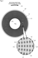
FIG. 2 is a view of a sliding surface of a stationary seal ring when viewed in an axial direction. -
FIG. 3A is a cross-sectional view taken along line A-A ofFIG. 2 , andFIG. 3B is a cross-sectional view taken along line B-B ofFIG. 2 . -
FIG. 4A is a schematic view illustrating the state of one recessed groove during relative rotation between sliding components when viewed in the axial direction, andFIG. 4B is a cross-sectional view taken along line C-C ofFIG. 4A . -
FIG. 5A is a schematic view illustrating a state where the relative rotation between the sliding components has further progressed than the state inFIG. 4 when viewed in the axial direction, andFIG. 5B is a cross-sectional view taken along line D-D ofFIG. 5A . -
FIG. 6A is a schematic view illustrating a state where the relative rotation between the sliding components has further progressed than the state inFIG. 5 when viewed in the axial direction, andFIG. 6B is a cross-sectional view taken along line D-D ofFIG. 6A . -
FIG. 7 is a cross-sectional view taken along line F-F ofFIG. 6B . -
FIG. 8A is a schematic view illustrating one example of the state of one recessed groove during the normal operation of the mechanical seal for a long period of time when viewed in the axial direction, andFIG. 8B is a cross-sectional view taken along line J-J ofFIG. 8A . -
FIG. 9 is an explanatory view illustrating a stationary seal ring in a first modification example of the first embodiment. -
FIG. 10 is an explanatory view illustrating a stationary seal ring in a second modification example of the first embodiment. -
FIGS. 11A to 11D are explanatory views illustrating dimples in third to sixth modification examples of the first embodiment. -
FIGS. 12A to 12F are explanatory views illustrating dimples in seventh to twelfth modification examples of the first embodiment. -
FIG. 13A is a schematic view of a recessed groove of a sliding component according to a second embodiment of the present invention when viewed in the axial direction,FIG. 13B is a cross-sectional view taken along line G-G ofFIG. 13A, and FIG. 13C is a cross-sectional view taken along line H-H ofFIG. 13A . -
FIG. 14 is an explanatory view illustrating a stationary seal ring as a sliding component according to a third embodiment of the present invention. -
FIG. 15A is a cross-sectional view taken along line K-K ofFIG. 14 , andFIG. 15B is a cross-sectional view taken along line L-L ofFIG. 14 . - Modes for implementing sliding components according to the present invention will be described below based on embodiments.
- A sliding component according to a first embodiment of the present invention will be described with reference to
FIGS. 1 to 7 . Incidentally, in the present embodiment, a mode in which the sliding components form a mechanical seal will be described as an example. In addition, a description will be made based on the assumption that a radially outer side of the sliding components forming a mechanical seal is a sealed fluid side (high-pressure side) and a radially inner side is an atmosphere side (low-pressure side) as a leakage side. In addition, for convenience of description, in the drawings, dots may be added to grooves and the like formed on a sliding surface. - The mechanical seal illustrated in
FIG. 1 is used, for example, in a shaft sealing device for a motor cooling system of an electric vehicle, and is an inside mechanical seal that seals a sealed fluid F tending to leak from the radially outer side toward the radially inner side of the sliding surface. Incidentally, in the present embodiment, a mode in which the sealed fluid F is cooling water will be provided as an example. - The mechanical seal mainly includes a
rotating seal ring 20 as a counterpart sliding member that is an annular sliding component provided on arotating shaft 1 via asleeve 2 to be rotatable integrally with therotating shaft 1, and astationary seal ring 10 having an annular shape which is a sliding component provided on aseal cover 5 fixed to ahousing 4 of an attached device to be non-rotatable and movable in an axial direction. Thestationary seal ring 10 is biased in the axial direction by a bellows 7, so that a slidingsurface 11 of thestationary seal ring 10 and a slidingsurface 21 of therotating seal ring 20 slide in close contact with each other. Incidentally, the slidingsurface 21 of therotating seal ring 20 is a flat surface, and a recessed portion is not provided on the flat surface. - The
stationary seal ring 10 and therotating seal ring 20 are typically made of SiC (as an example of hard material) or a combination of SiC and carbon (as an example of soft material), but are not limited thereto, and any sliding material can be applied as long as the sliding material is used as a sliding material for a mechanical seal. Incidentally, examples of SiC include sintered bodies using boron, aluminum, carbon, or the like as a sintering aid, and materials consisting of two or more phases with different components and compositions, such as SiC in which graphite particles are dispersed, reaction-sintered SiC consisting of SiC and Si, SiC-TiC, and SiC-TiN. As the carbon, carbon in which a carbonaceous substance and a graphitic substance are mixed, resin-molded carbon, sintered carbon, and the like can be used. In addition, in addition to the above-described sliding materials, metal materials, resin materials, surface modification materials (e.g., coating materials), composite materials, and the like can also be applied. As will be described later, a material containing SiC as a main component is preferable from the viewpoint of water retention. - As illustrated in
FIG. 2 , therotating seal ring 20 slides relative to thestationary seal ring 10 as indicated by an arrow. A plurality of recessedstrip grooves 14 are provided on the slidingsurface 11 of thestationary seal ring 10 as recessed strip portions. Portions of the slidingsurface 11 other than the recessedstrip grooves 14 arelands 12, and the recessedstrip grooves 14 and thelands 12 are alternately disposed in a radial direction. - As illustrated in
FIGS. 2 and3 , the plurality of recessedstrip grooves 14 have an endless annular shape, and are provided concentrically with the slidingsurface 11 while being spaced apart from each other at a predetermined pitch width in the radial direction. Namely, the plurality of recessedstrip grooves 14 are independently provided in the radial direction, and the recessed strip grooves are not in communication with each other. Each recessedstrip groove 14 has a width dimension L1 in the radial direction. In addition, the recessedstrip groove 14 has a constant depth dimension L5 in a circumferential direction and the radial direction. Incidentally, for convenience of description, the depth of the recessedstrip groove 14 or the depth of adimple 15 to be described later is illustrated to be deeper and schematically than the actual depth. - A width dimension L2 of the
land 12 in the radial direction is slightly smaller than the width dimension L1 of the recessedstrip groove 14 in the radial direction (L1 > L2). Incidentally, in the present embodiment, a mode in which the width dimension L2 of theland 12 is smaller than the width dimension L1 of the recessedstrip groove 14 has been provided as an example; however, the width of the land between the recessed strip grooves may be larger than the width of the recessed strip groove, or the width of the land and the width of the recessed strip groove may be the same. From the viewpoint of forming aplateau layer 16 to be described later, it is preferable that the width dimension L1 of the land is larger than 1/3 times and smaller than 3 times the width dimension L2 of the recessed strip groove (1/3L2 < L1 < 3L2). - In addition, a
top portion 12a of theland 12 is curved to protrude toward arotating seal ring 20 side. - A
bottom portion 14a of the recessedstrip groove 14 is curved in a recess direction, namely, a direction opposite to an end surface of the land 12 (namely, downward inFIG. 3 ). - A plurality of the
dimples 15 are evenly disposed spaced apart from each other in a longitudinal direction of the recessedstrip groove 14, namely, the circumferential direction on thebottom portion 14a of the recessedstrip groove 14. Thedimples 15 are disposed radially from a relative rotation center O of the slidingsurface 11 when viewed in the axial direction. Eachdimple 15 has a hemispherical shape that is open to the recessedstrip groove 14, and has an upward facing C-shaped cross section and a circular shape when viewed in the axial direction. - A radial dimension L3 of the
dimple 15 is slightly smaller than the width dimension L1 of the recessed strip groove 14 (L1 > L3). Incidentally, the radial dimension L3 of thedimple 15 may be the same as the width dimension L1 of the recessedstrip groove 14 or may be larger than the width dimension L1 of the recessedstrip groove 14; however, from the viewpoint of forming theplateau layer 16 to be described later, it is preferable that the radial dimension L3 of thedimple 15 is larger than 1/3 times the width dimension L1 of the recessedstrip groove 14 and less than or equal to the width dimension L1 of the recessed strip groove 14 (1/3L1 < L3 ≤ L1). - In addition, a depth dimension L4 of the
dimple 15 is smaller than the depth dimension L5 of the recessed strip groove 14 (L4 < L5). Incidentally, the depth dimension L4 of thedimple 15 may be the same as the depth dimension L5 of the recessedstrip groove 14 or may be larger than the depth dimension L5 of the recessedstrip groove 14; however, from the viewpoint of forming theplateau layer 16 to be described later, it is preferable that the depth dimension L4 is larger than 1/3 times and smaller than 3 times the depth dimension L5 of the recessed strip groove 14 (1/3L5 < L4 ≤ 3L5). - The
stationary seal ring 10 of the present embodiment is configured by forming the recessedstrip grooves 14 on the slidingsurface 11 and then forming thedimples 15 on thebottom portions 14a of the recessedstrip grooves 14. Incidentally, after thedimples 15 are formed on the slidingsurface 11, the recessedstrip grooves 14 may be formed. - Next, the operation during relative rotation between the
stationary seal ring 10 and therotating seal ring 20 in a break-in operation performed before the normal operation of the mechanical seal will be described usingFIGS. 4 to 6 . Incidentally, inFIGS. 4 to 6 , the movement of the sealed fluid F or wearproducts 30 in one recessedstrip groove 14 will be described. Furthermore, inFIGS. 4 to 6 , a change in height due to wear of thelands 12 is illustrated to be larger than the actual change. - First, during non-operation in which the
rotating seal ring 20 is not in rotation, the sealed fluid F is stored in the recessedstrip groove 14. Incidentally, since thestationary seal ring 10 is biased toward therotating seal ring 20 side by the bellows 7, there is substantially no leakage from between the slidingsurfaces - As illustrated in
FIG. 4 , when therotating seal ring 20 rotates relative to thestationary seal ring 10, the sealed fluid F stored in the recessedstrip groove 14 follows and moves in a rotation direction (refer to an arrow) of therotating seal ring 20 due to friction with the slidingsurface 21. Specifically, the sealed fluid F moves along the recessedstrip groove 14 extending along a relative rotation direction of therotating seal ring 20. Incidentally, the height of theland 12 in the state inFIG. 4 is a dimension L10. - In this case, the
land 12 of thestationary seal ring 10 and the flat surface of the slidingsurface 21 of therotating seal ring 20 come into local contact with each other, so that thefine wear products 30 are generated. As described above, since thetop portion 12a of theland 12 is curved to protrude toward therotating seal ring 20 side, the formation of large wear products is suppressed. Thewear products 30 may originate from thestationary seal ring 10, may originate from therotating seal ring 20, or may be a mixture thereof. - The
fine wear products 30 move along the recessedstrip groove 14 together with the sealed fluid F. Some of thewear products 30 moving along the recessedstrip groove 14 is trapped in thedimple 15. Specifically, a surface on a downstream side of the relative rotation, which forms thedimple 15, is disposed at a lower position than thebottom portion 14a of the recessedstrip groove 14, and the surface traps thewear products 30. - In addition, due to sliding between the
top portion 12a of theland 12 and the slidingsurface 21 of therotating seal ring 20, the unevenness of thetop portion 12a of theland 12 is worn out and theplateau layer 16 is formed (refer toFIG. 7 ). - The
plateau layer 16 has good break-in with the slidingsurface 21, and can exhibit a low wear state. - As illustrated in
FIG. 5 , when therotating seal ring 20 further rotates relative to thestationary seal ring 10 from the state inFIG. 4 , thewear products 30 are further trapped in thedimple 15. - In addition, the height of the
land 12 in the state inFIG. 5 is a dimension L10' smaller than the dimension L10 due to wear (L10 > L10'). - As illustrated in
FIG. 6 , when therotating seal ring 20 further rotates relative to thestationary seal ring 10 from the state inFIG. 5 , thewear products 30 are deposited in thedimple 15, and are deposited in layers on thebottom portion 14a of the recessedstrip groove 14. Namely, a large amount of thewear products 30 exist around thebottom portion 14a of the recessedstrip groove 14 or eachdimple 15. Incidentally, the height of theland 12 in the state inFIG. 6 is a dimension L10'' smaller than the dimension L10' (L10' > L10''). - The break-in operation is completed when a predetermined time elapses or the coefficient of friction becomes less than or equal to a predetermined value. In this completed state, the
plateau layer 16 is sufficiently formed, and lubricity between the slidingsurfaces - When the normal operation of the mechanical seal is performed for a long period of time, as illustrated in
FIG. 8 , thewear products 30 may be deposited in substantially the entirety of the recessedstrip groove 14 due to the progress of wear of theland 12. In this state, since the layer of thewear products 30 deposited in the recessedstrip groove 14 is more easily deformed upon the receipt of an external force than theland 12, a force received from therotating seal ring 20 is mainly received by theland 12. In addition, since many voids exist between thewear products 30, a wide surface area thereof is secured, and thewear products 30 have SiC as a main component, the layer of thewear products 30 deposited in the recessedstrip groove 14 can hold a large amount of the sealed fluid F. For these reasons, high lubricity between the slidingsurfaces - As described above, since the
wear products 30 flowing along the recessedstrip groove 14 are trapped and deposited by thedimples 15 provided on the recessedstrip groove 14, thefine wear products 30 serving as a lubricant can be effectively retained in the recessedstrip groove 14. - In addition, since the sealed fluid F can be held in the fine gaps between the
wear products 30, lubricity between the slidingsurfaces - In addition, the plurality of recessed
strip grooves 14 are independently provided in the radial direction. In other words, since the recessedstrip grooves 14 are not in communication with a sealed fluid F side or an atmosphere A side which is an external space, the discharge of thewear products 30 from the recessedstrip grooves 14 to the sealed fluid F side or the atmosphere A side can be suppressed. Therefore, thefine wear products 30 can be effectively retained in the recessedstrip grooves 14. - Further, during relative rotation between the sliding
surfaces strip grooves 14. When a positive pressure or negative pressure has occurred in the recessedstrip grooves 14, a force acts on the slidingsurfaces surfaces surfaces - In addition, since the recessed
strip grooves 14 have an endless annular shape, thewear products 30 circulating around the recessedstrip grooves 14 are easily trapped by thedimples 15. In addition, since the force caused by the recessedstrip grooves 14 and acting in the direction in which the slidingsurfaces surfaces surfaces strip grooves 14, thewear products 30 can be prevented from being concentrated and deposited at the end portions. - In addition, since the
bottom portions 14a of the recessedstrip grooves 14 are curved in the recess direction, namely, in the direction opposite to the end surfaces of thelands 12, thewear products 30 moving along the recessedstrip grooves 14 are guided toward thedimples 15 by thebottom portions 14a. - In addition, since the plurality of
dimples 15 are evenly disposed in the longitudinal direction of the recessedstrip grooves 14, thewear products 30 can be deposited in a well-balanced manner by being dispersed in the longitudinal direction of the recessedstrip grooves 14. In addition, since thedimples 15 are spaced apart from each other in the circumferential direction, wear sections in which thewear products 30 are generated can be secured on the slidingsurfaces - In addition, steps for trapping the
wear products 30 are configured such that thedimples 15 are provided on thebottom portions 14a of the recessedstrip grooves 14 and the surfaces on the downstream side of the relative rotation, which form thedimples 15, trap thewear products 30. According to this configuration, since thedimples 15 are recessed portions that are recessed in a depth direction from thebottom portions 14a of the recessedstrip grooves 14, a large space for accommodating thefine wear products 30 can be secured. In addition, since the shape is simple, thedimples 15 can be easily formed. - In addition, since the
dimples 15 have a circular shape when viewed in the axial direction and no corner portions are formed, thewear products 30 are easily trapped in thedimples 15 in a well-balanced manner. - In addition, the
stationary seal ring 10 is made of SiC, and thewear products 30 of SiC have high hydrophilicity. In addition, since thefine wear products 30 have a wide surface area, water can be suitably held around the recessedstrip grooves 14 or thedimples 15, and lubricity can be enhanced. - In addition, in the first embodiment, a mode in which the
dimples 15 are disposed to be scattered radially from the relative rotation center O of the slidingsurface 11 when viewed in the axial direction has been provided as an example; however, the present invention is not limited thereto, and for example, as in the case of astationary seal ring 100 of a first modification example illustrated inFIG. 9 ,dimples 151 may be randomly formed to be non-evenly disposed in the longitudinal direction of the recessedstrip grooves 14. - In addition, in the first embodiment, a mode in which the
dimples 15 are disposed only in the recessedstrip grooves 14 has been provided as an example; however, the present invention is not limited thereto, and the dimples may include at least dimples disposed in the recessedstrip grooves 14, or may be disposed across thelands 12 and the recessedstrip grooves 14. For example, as in the case of astationary seal ring 101 of a second modification example illustrated inFIG. 10 ,dimples 251a provided on thebottom portions 14a of the recessedstrip grooves 14,dimples 251b provided on thelands 12, anddimples 251c provided across the recessedstrip groove 14 and thelands 12 may be formed. - Incidentally, although not illustrated, the dimples may be provided to be scattered in a grid pattern on the sliding surface.
- In addition, in the first embodiment, a mode in which the
dimple 15 has a hemispherical shape that is curved in the recess direction in a cross-sectional view has been provided as an example; however, the present invention is not limited thereto. Incidentally, inFIGS. 11 and12 , an up-down direction of the drawing sheets and a left-right direction of the drawing sheets will be described as the circumferential direction and the radial direction, respectively. - For example, as in the case of a
dimple 300 of a third modification example illustrated inFIG. 11A , the dimple may have a crescent shape in a cross-sectional view which is shallower than thedimple 15 of the first embodiment. - In addition, for example, as in the case of a
dimple 301 of a fourth modification example illustrated inFIG. 11B , the dimple may have a U-shape in a cross-sectional view. - In addition, for example, as in the case of a
dimple 302 of a fifth modification example illustrated inFIG. 11C , the dimple may have a rectangular shape in a cross-sectional view. - In addition, for example, as in the case of a
dimple 303 of a sixth modification example illustrated inFIG. 11D , the dimple may have a triangular shape in a cross-sectional view. - In addition, in the first embodiment, a mode in which the
dimple 15 has a circular shape when viewed in the axial direction has been provided as an example; however, the present invention is not limited thereto. For example, as in the case of adimple 400 of a seventh modification example illustrated inFIG. 12A , the dimple may have an elliptical shape when viewed in the axial direction. Incidentally, thedimple 400 may have an elliptical shape that is long in the circumferential direction, or may be an elliptical shape that is long in the radial direction. - In addition, for example, as in the case of a
dimple 401 of an eighth modification example illustrated inFIG. 12B , the dimple may have a long hole shape havingcurved surfaces 401a, which bulge to the outside of thedimple 401, at both ends in the longitudinal direction when viewed in the axial direction. Incidentally, thedimple 401 may be long in the circumferential direction, or may be long in the radial direction. Furthermore, thecurved surfaces 401a may be formed to bulge to the inside of thedimple 401. - In addition, for example, as in the case of a
dimple 402 of a ninth modification example illustrated inFIG. 12C , the dimple may have an oblong shape that is long in the radial direction when viewed in the axial direction. - In addition, for example, as in the case of a
dimple 403 of a tenth modification example illustrated inFIG. 12D , the dimple may have an oblong shape that is long in the circumferential direction when viewed in the axial direction. Incidentally, although not illustrated, the dimple may have a square shape when viewed in the axial direction. - In addition, for example, as in the case of a
dimple 404 of an eleventh modification example illustrated inFIG. 12E , the dimple may have a long hole shape havingcurved surfaces 404a, which bulge to the inside of thedimple 404, at both ends in a traverse direction when viewed in the axial direction. Incidentally, thedimple 404 may be long in the circumferential direction, or may be long in the radial direction. Furthermore, thecurved surfaces 404a may be formed to bulge to the outside of thedimple 404. - In addition, for example, as in the case of a
dimple 405 of a twelfth modification example illustrated inFIG. 12F , the dimple may be formed in a zigzag shape when viewed in the axial direction. Incidentally, corner portions of thedimple 405 may be curved. - Next, a sliding component according to a second embodiment of the present invention will be described with reference to
FIG. 13 . Incidentally, the description of configurations that are the same as and overlap with the configurations of the first embodiment will be omitted. - As illustrated in
FIG. 13 , in astationary seal ring 110 as the sliding component according to the second embodiment of the present embodiment, awall portion 152 is erected from abottom portion 142a of a recessedstrip groove 142 acrossside portions 142b of the recessedstrip groove 142, namely, side surfaces of thelands 12. Thewall portion 152 has a height dimension smaller than a height dimension of theland 12. - Since the
wall portion 152 traps thewear products 30 moving along the recessedstrip groove 142, thewear products 30 can be effectively retained in the recessedstrip groove 142. Namely, thewall portion 152 functions as a step for trapping wear products. - Incidentally, the
wall portion 152 is not limited to being formed from thebottom portion 142a of the recessedstrip groove 142 across theside portions 142b of the recessedstrip groove 142, and for example, the wall portion may rise from the bottom portion of the recessed strip groove while being spaced apart from the side portions of the recessed strip groove. Namely, the wall portion may be a step capable of trapping wear products. - Next, a sliding component according to a third embodiment of the present invention will be described with reference to
FIGS. 14 and15 . Incidentally, the description of configurations that are the same as and overlap with the configurations of the first embodiment will be omitted. - As illustrated in
FIGS. 14 ,15A, and 15B , a plurality of recessedstrip grooves 514 having a uniform depth are provided on a slidingsurface 511 of astationary seal ring 510 of the present embodiment. Portions of the slidingsurface 511 other than the recessedstrip grooves 514 arelands 512 having a uniform height. - Specifically, one recessed
strip groove 514 extends in the radial direction to obliquely pass through the relative rotation center O of the 511 when viewed in the axial direction. The other recessedstrip grooves 514 extend substantially parallel to the one recessedstrip groove 514, and are formed spaced apart from each other at a predetermined pitch width. Namely, each recessedstrip groove 514 extends in a direction intersecting the axial direction. In other words, each recessedstrip groove 514 extends to be inclined with respect to the circumferential direction of the slidingsurface 511. - In addition, the recessed
strip grooves 514 are formed by laser-processing the surface of the base material of thestationary seal ring 510. When laser processing is performed, anamorphous layer 516 is formed on the surface. Theamorphous layer 516 is easily peeled off. Namely, the slidingsurface 511 easily generates wear products. Incidentally, in the first and second embodiments, by forming the recessedstrip grooves surface 511 is allowed to easily generate wear products. - As illustrated in
FIGS. 14 and15A , a plurality ofdimples 515 are evenly disposed on abottom portion 514a of each recessedstrip groove 514 while being spaced apart from each other in a longitudinal direction of the recessedstrip groove 514. Thedimples 515 are disposed radially from the relative rotation center O of the slidingsurface 511 when viewed in the axial direction. Incidentally, the dimples may be randomly disposed, may be radially disposed, or may be disposed in a grid pattern. - When the
rotating seal ring 20 rotates relative to thestationary seal ring 510, wear products flow along the recessedstrip grooves 514, and are accumulated on thedimples 515 and thebottom portions 514a. The wear products of SiC have high hydrophilicity, so that the accumulated wear products can suitably hold water and lubricity can be enhanced. - Incidentally, in the third embodiment, one recessed
strip groove 514 extends in the radial direction to obliquely pass through the relative rotation center O of the slidingsurface 511 when viewed in the axial direction, and the other recessedstrip grooves 514 extend substantially parallel to the one recessedstrip groove 514, and are formed spaced apart from each other at the predetermined pitch width; however, for example, in addition to the above-described recessed strip grooves 514 (the one recessedstrip groove 514 and the other recessed strip grooves 514), a plurality of other recessedstrip grooves 514 may be provided to intersect the above-described recessedstrip grooves 514, and the recessedstrip grooves 514 may be orthogonal to each other, or the recessedstrip grooves 514 may simply intersect each other without being orthogonal to each other. - Incidentally, in the third embodiment, a mode in which the
dimples 515 are formed in the recessedstrip grooves 514 has been provided as an example; however, for example, as in the second modification example (refer toFIG. 10 ), thedimples 515 may be provided across the land or the recessed strip groove and the land. - The embodiments of the present invention have been described above with reference to the drawings; however, the specific configurations are not limited to the embodiments, and changes or additions that are made without departing from the scope of the present invention are included in the present invention.
- For example, in the first to third embodiments, a mode in which the plurality of recessed grooves are independently provided has been provided as an example; however, at least one recessed groove may be provided. In addition, some of the recessed grooves of the first and second embodiments may communicate with an external space on the radially outer side or an external space on the radially inner side, and the recessed grooves of the third embodiment may not communicate with the external space on the radially outer side or the external space on the radially inner side.
- In addition, in the first and second embodiments, a mode in which the recessed grooves have an endless annular shape has been provided as an example, and in the third embodiment, a mode in which the recessed grooves extend in the direction intersecting the axial direction has been provided as an example; however, for example, the recessed grooves may be grooves extending in the circumferential direction, grooves extending in the radial direction, or grooves having a component extending in the radial direction and a component extending in the circumferential direction.
- In addition, in the first and second embodiments, a mode in which the depth of the recessed strip portions is constant in the circumferential direction has been provided as an example, and in the third embodiment, a mode in which the depth of the recessed strip portions is constant in the longitudinal direction has been provided as an example; however, for example, the bottom portion of each recessed strip portion may have a tapered shape such that a part of the bottom portion becomes shallower or deeper as the bottom portion extends toward one side in the relative rotation direction.
- In addition, in the first to third embodiments, a mechanical seal for automobiles has been described as an example of the sliding components; however, the present invention may be applied to other mechanical seals for general industrial machines, water pumps, or the like. In addition, the present invention is not limited to the mechanical seal, and may be applied to sliding components other than the mechanical seal, such as a slide bearing.
- In addition, in the first to third embodiments, an example in which the recessed strip grooves are provided only on the stationary seal ring has been described; however, the recessed strip grooves may be provided only on the rotating seal ring, or may be provided on both the stationary seal ring and the rotating seal ring.
- In addition, in the first to third embodiments, the sealed fluid side and the leakage side have been described as a high-pressure side and a low-pressure side, respectively; however, the sealed fluid side and the leakage side may be a low-pressure side and a high-pressure side, respectively, or the sealed fluid side and the leakage side may have substantially the same pressure.
- In addition, in the first to third embodiments, a mode in which the mechanical seal is an inside mechanical seal that seals the sealed fluid F tending to leak from the radially outer side toward the radially inner side of the sliding surfaces has been provided as an example; however, the present invention is not limited thereto, and the mechanical seal may be an outside mechanical seal that seals the sealed fluid F tending to leak from the radially inner side toward the radially outer side of the sliding surfaces.
- In addition, in the first to third embodiments, a mode in which the sealed fluid F is cooling water has been provided as an example; however, the present invention is not limited thereto, the sealed fluid may be a liquid or a mist mixture of a liquid and a gas, and for example, may be lubricating oil or the like.
-
- 10
- Stationary seal ring (sliding component)
- 11
- Sliding surface
- 12
- Land
- 12a
- Top portion
- 14
- Recessed strip groove (recessed strip portion)
- 14a
- Bottom portion
- 15
- Dimple (step)
- 16
- Plateau layer
- 20
- Rotating seal ring
- 21
- Sliding surface
- 30
- Wear product
- 100
- Stationary seal ring
- 110
- Stationary seal ring
- 142
- Recessed strip groove
- 142a
- Bottom portion
- 142b
- Side portion
- 151
- Dimple
- 152
- Wall portion
- A
- Atmosphere
- C
- Upward facing cross section
- F
- Sealed fluid
- Fa
- Sealed fluid
- L1
- Width dimension
- L10
- Dimension
- L10'
- Dimension
- L10''
- Dimension
- L2
- Width dimension
- L3
- Radial dimension
- L4
- Depth dimension
- L5
- Depth dimension
Claims (8)
- A sliding component that is disposed at a location of relative rotation of a rotating machine and that slides relative to a counterpart sliding member,wherein a recessed strip portion is formed on a sliding surface of the sliding component, andthe recessed strip portion is provided with a step having a difference in height, which traps a wear product.
- The sliding component according to claim 1,
wherein a plurality of the recessed strip portions are independently provided in a radial direction. - The sliding component according to claim 1,
wherein the recessed strip portion has an endless annular shape. - The sliding component according to claim 1,
wherein a bottom portion of the recessed strip portion is curved to be further recessed in a recess direction of the recessed strip portion. - The sliding component according to claim 1,
wherein a plurality of the steps are disposed spaced apart from each other in a longitudinal direction of the recessed strip portion. - The sliding component according to any one of claims 1 to 5,
wherein a dimple is disposed on a bottom portion of the recessed strip portion, and a part of the dimple forms the step. - The sliding component according to claim 6,
wherein the dimple has a circular shape when viewed in an axial direction. - The sliding component according to claim 1,
wherein the sliding component is made of SiC.
Applications Claiming Priority (2)
| Application Number | Priority Date | Filing Date | Title |
|---|---|---|---|
| JP2022092385 | 2022-06-07 | ||
| PCT/JP2023/021113 WO2023238883A1 (en) | 2022-06-07 | 2023-06-07 | Sliding component |
Publications (2)
| Publication Number | Publication Date |
|---|---|
| EP4538551A1 true EP4538551A1 (en) | 2025-04-16 |
| EP4538551A4 EP4538551A4 (en) | 2026-05-20 |
Family
ID=89118340
Family Applications (1)
| Application Number | Title | Priority Date | Filing Date |
|---|---|---|---|
| EP23819863.4A Pending EP4538551A4 (en) | 2022-06-07 | 2023-06-07 | SLIDING COMPONENT |
Country Status (6)
| Country | Link |
|---|---|
| US (1) | US12578019B2 (en) |
| EP (1) | EP4538551A4 (en) |
| KR (1) | KR20250011150A (en) |
| CN (1) | CN119301388A (en) |
| TW (1) | TWI898223B (en) |
| WO (1) | WO2023238883A1 (en) |
Families Citing this family (1)
| Publication number | Priority date | Publication date | Assignee | Title |
|---|---|---|---|---|
| CN121336063A (en) * | 2023-07-07 | 2026-01-13 | 伊格尔工业股份有限公司 | sliding parts |
Family Cites Families (46)
| Publication number | Priority date | Publication date | Assignee | Title |
|---|---|---|---|---|
| US2247505A (en) | 1939-01-13 | 1941-07-01 | Joseph H Kohler | Seal |
| NL130801C (en) | 1961-02-10 | |||
| US3804424A (en) * | 1972-04-24 | 1974-04-16 | Crane Packing Co | Gap seal with thermal and pressure distortion compensation |
| US3957276A (en) | 1975-04-10 | 1976-05-18 | Borg-Warner Corporation | Mechanical seal with pressurized lubrication pockets |
| US5743654A (en) * | 1987-05-29 | 1998-04-28 | Kmc, Inc. | Hydrostatic and active control movable pad bearing |
| US5174584A (en) * | 1991-07-15 | 1992-12-29 | General Electric Company | Fluid bearing face seal for gas turbine engines |
| JP3781463B2 (en) | 1995-11-10 | 2006-05-31 | 株式会社ニクニ | mechanical seal |
| US6152452A (en) | 1997-10-17 | 2000-11-28 | Wang; Yuming | Face seal with spiral grooves |
| CN100427816C (en) * | 2002-09-20 | 2008-10-22 | 徐万福 | Helical flute and face mechanial seal composed of angular microflute group |
| EP1517057A3 (en) | 2003-09-22 | 2007-05-16 | Relial Corporation | Dynamic pressure thrust bearing part and method of manufacturing dynamic pressure thrust bearing part |
| JP4719414B2 (en) | 2003-12-22 | 2011-07-06 | イーグル工業株式会社 | Sliding parts |
| CN102322526B (en) * | 2004-11-09 | 2014-10-22 | 伊格尔工业股份有限公司 | Mechanical seal device |
| CN101644333B (en) * | 2009-08-20 | 2011-08-31 | 浙江工业大学 | Gas end surface sealing structure with three-dimensional feather-like textured bottom shaped grooves |
| US8888104B2 (en) * | 2010-09-16 | 2014-11-18 | Stein Seal Company | Intershaft seal system for minimizing pressure induced twist |
| EP2626604B1 (en) | 2010-10-06 | 2019-06-12 | Eagle Industry Co., Ltd. | Sliding part |
| JP2013002522A (en) * | 2011-06-15 | 2013-01-07 | Nissan Motor Co Ltd | Driving force transmission apparatus |
| EP2752602B1 (en) * | 2011-09-03 | 2018-04-11 | Eagle Industry Co., Ltd. | Sliding component |
| WO2013035502A1 (en) | 2011-09-10 | 2013-03-14 | イーグル工業株式会社 | Sliding component |
| DE202012100316U1 (en) * | 2012-01-31 | 2012-03-05 | Chetra Gmbh Dichtungstechnik | Gas-lubricated mechanical seal |
| CN104185756B (en) * | 2012-05-21 | 2016-10-26 | 伊格尔工业股份有限公司 | Slide unit |
| CN104736904B (en) | 2013-01-16 | 2017-04-05 | 伊格尔工业股份有限公司 | Slide unit |
| US9574667B2 (en) * | 2013-03-14 | 2017-02-21 | Eagle Burgmann Japan Co., Ltd. | Mechanical seal device |
| CN104769341B (en) | 2013-03-17 | 2017-04-05 | 伊格尔工业股份有限公司 | Slide unit |
| FR3009124A1 (en) * | 2013-07-24 | 2015-01-30 | Areva Np | ICE FOR SEAL TRIM FOR TREE SEALING SYSTEM |
| AU2014362551B2 (en) | 2013-12-09 | 2017-06-01 | Eagle Industry Co., Ltd. | Sliding component |
| CN110081173B (en) * | 2014-01-24 | 2021-04-30 | Nok株式会社 | Sealing ring |
| WO2015199172A1 (en) | 2014-06-26 | 2015-12-30 | イーグル工業株式会社 | Sliding component |
| US9714712B2 (en) | 2014-08-15 | 2017-07-25 | Eaton Corporation | Hydrodynamic mating ring with integrated groove inlet pressure control |
| CN107407424B (en) | 2015-04-15 | 2019-11-22 | 伊格尔工业股份有限公司 | sliding parts |
| EP3318784B1 (en) | 2015-06-30 | 2020-07-01 | Eagle Industry Co., Ltd. | Seal device |
| JP6890611B2 (en) * | 2016-11-18 | 2021-06-18 | イーグル工業株式会社 | Sliding member |
| EP3575643B1 (en) | 2017-01-30 | 2023-03-22 | Eagle Industry Co., Ltd. | Sliding component |
| CN110770456B (en) * | 2017-07-07 | 2021-11-09 | 伊格尔工业股份有限公司 | Sliding component |
| CN107269847B (en) * | 2017-07-11 | 2019-10-11 | 浙江工业大学 | Turtle-like textured shape of a shell-like groove liquid-lubricated mechanical seal structure |
| JP6920977B2 (en) | 2017-12-18 | 2021-08-18 | キヤノンマシナリー株式会社 | Sliding surface structure |
| EP3748205B1 (en) * | 2018-02-01 | 2024-12-18 | Eagle Industry Co., Ltd. | Sliding parts |
| CN112088266B (en) | 2018-05-17 | 2022-12-06 | 伊格尔工业股份有限公司 | sealing ring |
| US11852241B2 (en) | 2019-02-04 | 2023-12-26 | Eagle Industry Co., Ltd. | Sliding component |
| WO2020162025A1 (en) | 2019-02-04 | 2020-08-13 | イーグル工業株式会社 | Sliding component |
| WO2020162349A1 (en) | 2019-02-04 | 2020-08-13 | イーグル工業株式会社 | Sliding component |
| CN115853894A (en) | 2019-02-04 | 2023-03-28 | 伊格尔工业股份有限公司 | sliding parts |
| WO2020166589A1 (en) * | 2019-02-14 | 2020-08-20 | イーグル工業株式会社 | Sliding components |
| JP7419346B2 (en) * | 2019-03-22 | 2024-01-22 | イーグル工業株式会社 | sliding parts |
| JP7190381B2 (en) | 2019-03-22 | 2022-12-15 | イーグル工業株式会社 | sliding parts |
| JP7441150B2 (en) * | 2020-09-23 | 2024-02-29 | 株式会社ジェイテクト | Wet friction disc and friction engagement device |
| CN112128381B (en) * | 2020-10-26 | 2021-07-20 | 常熟理工学院 | A sealing device for gas-liquid two-phase fluid medium with variable working conditions |
-
2023
- 2023-06-07 TW TW112121284A patent/TWI898223B/en active
- 2023-06-07 US US18/871,420 patent/US12578019B2/en active Active
- 2023-06-07 WO PCT/JP2023/021113 patent/WO2023238883A1/en not_active Ceased
- 2023-06-07 KR KR1020247041189A patent/KR20250011150A/en active Pending
- 2023-06-07 CN CN202380044287.5A patent/CN119301388A/en active Pending
- 2023-06-07 EP EP23819863.4A patent/EP4538551A4/en active Pending
Also Published As
| Publication number | Publication date |
|---|---|
| KR20250011150A (en) | 2025-01-21 |
| JPWO2023238883A1 (en) | 2023-12-14 |
| US20250354609A1 (en) | 2025-11-20 |
| EP4538551A4 (en) | 2026-05-20 |
| WO2023238883A1 (en) | 2023-12-14 |
| TW202400913A (en) | 2024-01-01 |
| US12578019B2 (en) | 2026-03-17 |
| TWI898223B (en) | 2025-09-21 |
| CN119301388A (en) | 2025-01-10 |
Similar Documents
| Publication | Publication Date | Title |
|---|---|---|
| EP3926187B1 (en) | Sliding components | |
| EP3816488B1 (en) | Seal ring | |
| EP3922871B1 (en) | Sliding component | |
| EP2881633B1 (en) | Sliding component | |
| EP2740974B1 (en) | Mechanical seal | |
| EP3926188A1 (en) | Sliding components | |
| EP3495638B1 (en) | Sealing device | |
| EP3816490A1 (en) | Seal ring | |
| EP3258145A1 (en) | Sliding component | |
| EP3929454B1 (en) | Sliding components | |
| US20240353007A1 (en) | Sliding components | |
| US12578019B2 (en) | Sliding component | |
| EP4372253A1 (en) | Sliding components | |
| EP4411182A1 (en) | Sliding component | |
| EP4130523B1 (en) | Sliding component | |
| EP4332415A1 (en) | Sliding component | |
| JP7817502B2 (en) | Sliding parts | |
| US20230375036A1 (en) | Sliding components | |
| EP4549763A1 (en) | Sliding component |
Legal Events
| Date | Code | Title | Description |
|---|---|---|---|
| STAA | Information on the status of an ep patent application or granted ep patent |
Free format text: STATUS: THE INTERNATIONAL PUBLICATION HAS BEEN MADE |
|
| PUAI | Public reference made under article 153(3) epc to a published international application that has entered the european phase |
Free format text: ORIGINAL CODE: 0009012 |
|
| STAA | Information on the status of an ep patent application or granted ep patent |
Free format text: STATUS: REQUEST FOR EXAMINATION WAS MADE |
|
| 17P | Request for examination filed |
Effective date: 20241209 |
|
| AK | Designated contracting states |
Kind code of ref document: A1 Designated state(s): AL AT BE BG CH CY CZ DE DK EE ES FI FR GB GR HR HU IE IS IT LI LT LU LV MC ME MK MT NL NO PL PT RO RS SE SI SK SM TR |
|
| DAV | Request for validation of the european patent (deleted) | ||
| DAX | Request for extension of the european patent (deleted) | ||
| A4 | Supplementary search report drawn up and despatched |
Effective date: 20260420 |
|
| RIC1 | Information provided on ipc code assigned before grant |
Ipc: F16C 17/04 20060101AFI20260414BHEP Ipc: F16C 33/24 20060101ALI20260414BHEP Ipc: F16J 15/34 20060101ALI20260414BHEP Ipc: F16C 33/10 20060101ALI20260414BHEP |