EP4538542A1 - Actuator assembly - Google Patents
Actuator assembly Download PDFInfo
- Publication number
- EP4538542A1 EP4538542A1 EP23306751.1A EP23306751A EP4538542A1 EP 4538542 A1 EP4538542 A1 EP 4538542A1 EP 23306751 A EP23306751 A EP 23306751A EP 4538542 A1 EP4538542 A1 EP 4538542A1
- Authority
- EP
- European Patent Office
- Prior art keywords
- assembly
- housing
- actuator
- integral housing
- rod
- Prior art date
- Legal status (The legal status is an assumption and is not a legal conclusion. Google has not performed a legal analysis and makes no representation as to the accuracy of the status listed.)
- Pending
Links
Images

Classifications
-
- F—MECHANICAL ENGINEERING; LIGHTING; HEATING; WEAPONS; BLASTING
- F15—FLUID-PRESSURE ACTUATORS; HYDRAULICS OR PNEUMATICS IN GENERAL
- F15B—SYSTEMS ACTING BY MEANS OF FLUIDS IN GENERAL; FLUID-PRESSURE ACTUATORS, e.g. SERVOMOTORS; DETAILS OF FLUID-PRESSURE SYSTEMS, NOT OTHERWISE PROVIDED FOR
- F15B15/00—Fluid-actuated devices for displacing a member from one position to another; Gearing associated therewith
- F15B15/18—Combined units comprising both motor and pump
-
- F—MECHANICAL ENGINEERING; LIGHTING; HEATING; WEAPONS; BLASTING
- F15—FLUID-PRESSURE ACTUATORS; HYDRAULICS OR PNEUMATICS IN GENERAL
- F15B—SYSTEMS ACTING BY MEANS OF FLUIDS IN GENERAL; FLUID-PRESSURE ACTUATORS, e.g. SERVOMOTORS; DETAILS OF FLUID-PRESSURE SYSTEMS, NOT OTHERWISE PROVIDED FOR
- F15B15/00—Fluid-actuated devices for displacing a member from one position to another; Gearing associated therewith
- F15B15/08—Characterised by the construction of the motor unit
- F15B15/14—Characterised by the construction of the motor unit of the straight-cylinder type
- F15B15/1423—Component parts; Constructional details
-
- F—MECHANICAL ENGINEERING; LIGHTING; HEATING; WEAPONS; BLASTING
- F15—FLUID-PRESSURE ACTUATORS; HYDRAULICS OR PNEUMATICS IN GENERAL
- F15B—SYSTEMS ACTING BY MEANS OF FLUIDS IN GENERAL; FLUID-PRESSURE ACTUATORS, e.g. SERVOMOTORS; DETAILS OF FLUID-PRESSURE SYSTEMS, NOT OTHERWISE PROVIDED FOR
- F15B21/00—Common features of fluid actuator systems; Fluid-pressure actuator systems or details thereof, not covered by any other group of this subclass
- F15B21/08—Servomotor systems incorporating electrically operated control means
- F15B21/085—Servomotor systems incorporating electrically operated control means using a data bus, e.g. "CANBUS"
-
- F—MECHANICAL ENGINEERING; LIGHTING; HEATING; WEAPONS; BLASTING
- F15—FLUID-PRESSURE ACTUATORS; HYDRAULICS OR PNEUMATICS IN GENERAL
- F15B—SYSTEMS ACTING BY MEANS OF FLUIDS IN GENERAL; FLUID-PRESSURE ACTUATORS, e.g. SERVOMOTORS; DETAILS OF FLUID-PRESSURE SYSTEMS, NOT OTHERWISE PROVIDED FOR
- F15B7/00—Systems in which the movement produced is definitely related to the output of a volumetric pump; Telemotors
- F15B7/005—With rotary or crank input
- F15B7/006—Rotary pump input
-
- F—MECHANICAL ENGINEERING; LIGHTING; HEATING; WEAPONS; BLASTING
- F15—FLUID-PRESSURE ACTUATORS; HYDRAULICS OR PNEUMATICS IN GENERAL
- F15B—SYSTEMS ACTING BY MEANS OF FLUIDS IN GENERAL; FLUID-PRESSURE ACTUATORS, e.g. SERVOMOTORS; DETAILS OF FLUID-PRESSURE SYSTEMS, NOT OTHERWISE PROVIDED FOR
- F15B2211/00—Circuits for servomotor systems
- F15B2211/20—Fluid pressure source, e.g. accumulator or variable axial piston pump
- F15B2211/205—Systems with pumps
- F15B2211/20507—Type of prime mover
- F15B2211/20515—Electric motor
-
- F—MECHANICAL ENGINEERING; LIGHTING; HEATING; WEAPONS; BLASTING
- F15—FLUID-PRESSURE ACTUATORS; HYDRAULICS OR PNEUMATICS IN GENERAL
- F15B—SYSTEMS ACTING BY MEANS OF FLUIDS IN GENERAL; FLUID-PRESSURE ACTUATORS, e.g. SERVOMOTORS; DETAILS OF FLUID-PRESSURE SYSTEMS, NOT OTHERWISE PROVIDED FOR
- F15B2211/00—Circuits for servomotor systems
- F15B2211/20—Fluid pressure source, e.g. accumulator or variable axial piston pump
- F15B2211/205—Systems with pumps
- F15B2211/2053—Type of pump
-
- F—MECHANICAL ENGINEERING; LIGHTING; HEATING; WEAPONS; BLASTING
- F15—FLUID-PRESSURE ACTUATORS; HYDRAULICS OR PNEUMATICS IN GENERAL
- F15B—SYSTEMS ACTING BY MEANS OF FLUIDS IN GENERAL; FLUID-PRESSURE ACTUATORS, e.g. SERVOMOTORS; DETAILS OF FLUID-PRESSURE SYSTEMS, NOT OTHERWISE PROVIDED FOR
- F15B2211/00—Circuits for servomotor systems
- F15B2211/20—Fluid pressure source, e.g. accumulator or variable axial piston pump
- F15B2211/205—Systems with pumps
- F15B2211/2053—Type of pump
- F15B2211/20561—Type of pump reversible
-
- F—MECHANICAL ENGINEERING; LIGHTING; HEATING; WEAPONS; BLASTING
- F15—FLUID-PRESSURE ACTUATORS; HYDRAULICS OR PNEUMATICS IN GENERAL
- F15B—SYSTEMS ACTING BY MEANS OF FLUIDS IN GENERAL; FLUID-PRESSURE ACTUATORS, e.g. SERVOMOTORS; DETAILS OF FLUID-PRESSURE SYSTEMS, NOT OTHERWISE PROVIDED FOR
- F15B2211/00—Circuits for servomotor systems
- F15B2211/20—Fluid pressure source, e.g. accumulator or variable axial piston pump
- F15B2211/205—Systems with pumps
- F15B2211/2053—Type of pump
- F15B2211/20569—Type of pump capable of working as pump and motor
-
- F—MECHANICAL ENGINEERING; LIGHTING; HEATING; WEAPONS; BLASTING
- F15—FLUID-PRESSURE ACTUATORS; HYDRAULICS OR PNEUMATICS IN GENERAL
- F15B—SYSTEMS ACTING BY MEANS OF FLUIDS IN GENERAL; FLUID-PRESSURE ACTUATORS, e.g. SERVOMOTORS; DETAILS OF FLUID-PRESSURE SYSTEMS, NOT OTHERWISE PROVIDED FOR
- F15B2211/00—Circuits for servomotor systems
- F15B2211/20—Fluid pressure source, e.g. accumulator or variable axial piston pump
- F15B2211/27—Directional control by means of the pressure source
-
- F—MECHANICAL ENGINEERING; LIGHTING; HEATING; WEAPONS; BLASTING
- F15—FLUID-PRESSURE ACTUATORS; HYDRAULICS OR PNEUMATICS IN GENERAL
- F15B—SYSTEMS ACTING BY MEANS OF FLUIDS IN GENERAL; FLUID-PRESSURE ACTUATORS, e.g. SERVOMOTORS; DETAILS OF FLUID-PRESSURE SYSTEMS, NOT OTHERWISE PROVIDED FOR
- F15B2211/00—Circuits for servomotor systems
- F15B2211/60—Circuit components or control therefor
- F15B2211/63—Electronic controllers
-
- F—MECHANICAL ENGINEERING; LIGHTING; HEATING; WEAPONS; BLASTING
- F15—FLUID-PRESSURE ACTUATORS; HYDRAULICS OR PNEUMATICS IN GENERAL
- F15B—SYSTEMS ACTING BY MEANS OF FLUIDS IN GENERAL; FLUID-PRESSURE ACTUATORS, e.g. SERVOMOTORS; DETAILS OF FLUID-PRESSURE SYSTEMS, NOT OTHERWISE PROVIDED FOR
- F15B2211/00—Circuits for servomotor systems
- F15B2211/60—Circuit components or control therefor
- F15B2211/63—Electronic controllers
- F15B2211/6303—Electronic controllers using input signals
Definitions
- EHAs electro-hydrostatic actuators
- PCM power control module
- REU remote electronic unit
- Actuators are used in a wide variety of fields and applications for moving parts or surfaces from one position to another. Actuators are commonly used, for example, in aircraft, for moving flight control surfaces or aircraft parts, doors etc. Many types of actuator are known, including mechanical, hydraulic and electrical actuators and combinations thereof e.g. electro-hydrostatic actuators, EHAs.
- An actuator typically has an actuator housing, or cylinder, within which an actuator ram or rod is located for axial movement relative to the housing. The rod is moved by application of power to one end of the rod. The other end of the rod is connected to a surface or part to be moved. Power is applied to the rod according to the type of actuator.
- the rod is moved by the application of hydraulic fluid provided from a hydraulic assembly in a hydraulic block.
- the hydraulic block is assembled to the actuator housing.
- the EHA assembly includes a motor and pump sub-assembly and is also provided with a power control module (PCM) and a remote electronics unit (REU).
- PCM power control module
- REU remote electronics unit
- the actuator power line is typically subjected to high levels of mechanical stress, it typically needs to be made of a strong material capable of withstanding such stresses, such as steel.
- a strong material capable of withstanding such stresses, such as steel.
- such materials are relatively expensive and heavy and it is usually desirable to reduce the overall weight and cost of an actuator assembly.
- the weight of aircraft parts should be minimised where possible, for reasons of efficiency.
- the reduce the overall weight and cost of the actuator assembly therefore, whilst maintaining the strength of the rod, it is common to fabricate the control block e.g. the hydraulic block, of a lighter material such as aluminium or, for higher pressure applications, titanium.
- lighter materials are not suitable for withstanding the high stresses applied to the rod, and so cannot be used for that part.
- the other main parts of the actuator assembly e.g. the motor-pump sub-assembly, the PCM and the REU are all conventionally manufactured and supplied as separate parts which are then assembled together.
- the requirement for multiple parts to be available to assemble into an actuator assembly increases the number of suppliers and the costs as well as assembly cost, complexity and time.
- the assembly is also relatively heavy. It would be desirable to have a lighter, simpler, less expensive and less time-intensive actuator assembly.
- an electro-hydrostatic actuator, EHA, assembly comprising: an actuator power line, and a one-piece, integral housing, housing a hydraulic control block, a power control module, PCM, and a motor-pump assembly, the integral housing comprising a passage through which the power line passes.
- a method of making an EHA assembly is also provided.
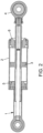
- the actuator comprises a power line 1 mounted to a hydraulic block 10.
- the power line is basically composed of a ram or rod 3 which is slidably located within a cylinder 1 and 2 attached to the structure (This part could either be in one part or in two parts), and moves relative to the cylinder responsive to the application of hydraulic fluid from the block.
- the rod is guided by two bearings 6 and 5 and links to the movable surface by the rod eye end 4.
- the actuator is driven by a motor and pump sub-assembly 12 to drive the operation of the hydraulic block to control the rate and direction of hydraulic fluid to move the rod relative to the cylinder.
- a power control module (here embedded PCM) 14 is mounted to the motor-pump sub-assembly to control the power to the motor-pump sub-assembly 12.
- Command and monitoring functions are provided by means of an electronics module (here remote electronics unit, REU) 16.
- the electronics module captures sensor data and sends command data to the actuator and is typically in electrical communication with the actuator via a digital data bus.
- the power line assembly needs to be made of a strong material that can withstand such stresses, e.g. steel or stainless steel.
- the hydraulic block 10 which is not subjected to such high mechanical stresses, is made of a lighter material such as aluminium or titanium.
- Each sub-assembly fitted onto the hydraulic block has its own housing. For aircraft applications, these are commonly made of aluminium. These parts are then assembled, e.g. bolted, together to form the actuator assembly. This results in a relatively complex, heavy and expensive multi-part assembly, potentially deriving from multiple, different (and commonly expensive) manufacturing processes.
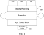
- a single, integral housing 100 is manufactured to house all of the hydraulic block, the motor-pump sub-assembly and the PCM.
- the integral housing is made using additive manufacturing.
- the integral housing 100 is also formed with a passage to receive the power line 200 therethrough.
- the actuator cylinder (part of the power line assembly) can be formed as an integral part of the housing or can be a separate cylinder, housing the rod, that fits in the passage of the integral housing. In this way, only a single, integral block need be manufactured, housing all of the hydraulic functions, motor-pump and PCM parts, that can be assembled over the actuator rod (or rod and cylinder).
- the electronics in the REU 300 will typically need to be separately configured for each actuator assembly and connected by electrical connectors, and, further, will need to be in a non-conductive, water-proof housing. Therefore, the electronics will usually still be formed in a separate REU 300, similar to that of the conventional assembly, and attached to the integral housing, with the appropriate electrical connections made through the integral housing 100.
- the parts making up the power line assembly due to the stress applied to it in use, will typically be made of a stronger material than the integral housing 100, e.g. stainless steel, but it is conceivable that other materials could be used.
Landscapes
- Engineering & Computer Science (AREA)
- Mechanical Engineering (AREA)
- General Engineering & Computer Science (AREA)
- Physics & Mathematics (AREA)
- Fluid Mechanics (AREA)
- Chemical & Material Sciences (AREA)
- Analytical Chemistry (AREA)
- Actuator (AREA)
- Fluid-Pressure Circuits (AREA)
- Combustion & Propulsion (AREA)
- Regulating Braking Force (AREA)
Abstract
An electro-hydrostatic actuator, EHA, assembly comprising: a power line (200), and a one-piece, integral housing (100) housing a hydraulic control block, a power control module, PCM, and a motor-pump assembly, the integral housing (100) comprising a passage through which the power line (200) passes.
Description
- The present disclosure is concerned with electro-hydrostatic actuators (EHAs) made up of the following sub-assembly: motor-pump, control hydraulic block with integrated hydraulic functions, accumulator, power line, power control module (PCM) and remote electronic unit (REU).
- Actuators are used in a wide variety of fields and applications for moving parts or surfaces from one position to another. Actuators are commonly used, for example, in aircraft, for moving flight control surfaces or aircraft parts, doors etc. Many types of actuator are known, including mechanical, hydraulic and electrical actuators and combinations thereof e.g. electro-hydrostatic actuators, EHAs. An actuator typically has an actuator housing, or cylinder, within which an actuator ram or rod is located for axial movement relative to the housing. The rod is moved by application of power to one end of the rod. The other end of the rod is connected to a surface or part to be moved. Power is applied to the rod according to the type of actuator. In some actuators (hydraulic, EHA, etc) the rod is moved by the application of hydraulic fluid provided from a hydraulic assembly in a hydraulic block. The hydraulic block is assembled to the actuator housing. In addition, the EHA assembly includes a motor and pump sub-assembly and is also provided with a power control module (PCM) and a remote electronics unit (REU).
- Because the actuator power line is typically subjected to high levels of mechanical stress, it typically needs to be made of a strong material capable of withstanding such stresses, such as steel. On the other hand, such materials are relatively expensive and heavy and it is usually desirable to reduce the overall weight and cost of an actuator assembly. In aircraft, in particular, the weight of aircraft parts should be minimised where possible, for reasons of efficiency. The reduce the overall weight and cost of the actuator assembly, therefore, whilst maintaining the strength of the rod, it is common to fabricate the control block e.g. the hydraulic block, of a lighter material such as aluminium or, for higher pressure applications, titanium. These lighter materials, however, are not suitable for withstanding the high stresses applied to the rod, and so cannot be used for that part.
- The other main parts of the actuator assembly e.g. the motor-pump sub-assembly, the PCM and the REU are all conventionally manufactured and supplied as separate parts which are then assembled together. The actuator assembly, especially the housing parts, therefore, typically are formed as a number of separate main structural parts, that are individually forged, machined or cast, that are then assembled together. The requirement for multiple parts to be available to assemble into an actuator assembly increases the number of suppliers and the costs as well as assembly cost, complexity and time. The assembly is also relatively heavy. It would be desirable to have a lighter, simpler, less expensive and less time-intensive actuator assembly.
- According to the disclosure, there is provided an electro-hydrostatic actuator, EHA, assembly comprising: an actuator power line, and a one-piece, integral housing, housing a hydraulic control block, a power control module, PCM, and a motor-pump assembly, the integral housing comprising a passage through which the power line passes.
- A method of making an EHA assembly is also provided.
- Examples of an actuator assembly according to this disclosure will now be described with reference to the drawings. It should be noted, that variations are possible within the scope of the claims.
-
Figure 1 shows a typical actuator assembly. -
Figure 2 shows a typical power line assembly -
Figure 3 shows an actuator assembly according to this disclosure. - The EHA shown in
Fig. 1 will be briefly described by way of background. The assembly will not be described in detail, since such actuators are well-known. - The power line shown in
Fig. 2 will be briefly described by way of background. The assembly will not be described in detail, since such actuators are well-known. - The actuator comprises a
power line 1 mounted to ahydraulic block 10. The power line is basically composed of a ram orrod 3 which is slidably located within acylinder bearings rod eye end 4. The actuator is driven by a motor andpump sub-assembly 12 to drive the operation of the hydraulic block to control the rate and direction of hydraulic fluid to move the rod relative to the cylinder. A power control module (here embedded PCM) 14 is mounted to the motor-pump sub-assembly to control the power to the motor-pump sub-assembly 12. Command and monitoring functions are provided by means of an electronics module (here remote electronics unit, REU) 16. The electronics module captures sensor data and sends command data to the actuator and is typically in electrical communication with the actuator via a digital data bus. - As mentioned above, due to the high mechanical stresses to which it is subjected, the power line assembly needs to be made of a strong material that can withstand such stresses, e.g. steel or stainless steel. Conventionally, to minimise overall weight and cost, however, the
hydraulic block 10, which is not subjected to such high mechanical stresses, is made of a lighter material such as aluminium or titanium. Each sub-assembly fitted onto the hydraulic block has its own housing. For aircraft applications, these are commonly made of aluminium. These parts are then assembled, e.g. bolted, together to form the actuator assembly. This results in a relatively complex, heavy and expensive multi-part assembly, potentially deriving from multiple, different (and commonly expensive) manufacturing processes. - In the assembly according to the disclosure, examples of which will be described with reference to
Fig. 3 , a single,integral housing 100 is manufactured to house all of the hydraulic block, the motor-pump sub-assembly and the PCM. In one example, the integral housing is made using additive manufacturing. Theintegral housing 100 is also formed with a passage to receive thepower line 200 therethrough. The actuator cylinder (part of the power line assembly) can be formed as an integral part of the housing or can be a separate cylinder, housing the rod, that fits in the passage of the integral housing. In this way, only a single, integral block need be manufactured, housing all of the hydraulic functions, motor-pump and PCM parts, that can be assembled over the actuator rod (or rod and cylinder). The electronics in the REU 300 will typically need to be separately configured for each actuator assembly and connected by electrical connectors, and, further, will need to be in a non-conductive, water-proof housing. Therefore, the electronics will usually still be formed in aseparate REU 300, similar to that of the conventional assembly, and attached to the integral housing, with the appropriate electrical connections made through theintegral housing 100. - The
integral housing 100 can be moulded, cast, forged or made by additive manufacturing in any size or shape capable of housing the actuator parts mentioned above. The integral housing is shaped to closely contain the relevant parts to keep the housing as compact as possible. Other envelopes are, however, possible. - The parts making up the power line assembly, due to the stress applied to it in use, will typically be made of a stronger material than the
integral housing 100, e.g. stainless steel, but it is conceivable that other materials could be used. - By forming a single, integral housing for the major EHA parts, only one part needs to be manufactured and supplied for assembly with the
power line 200, rather than several parts that need to be sourced and assembled. The integral housing can be easily and inexpensively formed using additive manufacture and may also be shaped in a topologically optimised form to save on size and weight.
Claims (12)
- An electro-hydrostatic actuator, EHA, assembly comprising:a power line (200), anda one-piece, integral housing (100) housing a hydraulic control block, a power control module, PCM, and a motor-pump assembly, the integral housing (100) comprising a passage through which the power line (200) passes.
- The assembly of claim 1, further comprising an actuator cylinder (1,2) within which the rod moves axially due to the pressure of hydraulic fluid from the hydraulic block.
- The assembly of claim 2, wherein the actuator cylinder (1, 2) is also formed in the integral housing (100).
- The assembly of any preceding claim, further comprising an electronics unit (300) containing electronic components for performing actuator command and/or monitoring functions, the electronics unit (300) being mounted to the integral housing (100).
- The assembly of any preceding claim, further comprising electrical connectors for electrically connecting the electronics unit (300) to sensor or commands lines of the actuator.
- The assembly of claim 5, wherein the electronics unit sends sensor and/or command signals via a digital data bus.
- The assembly of any preceding claim, wherein the integral housing is shaped to define a portion (110) shaped to correspond to the shape of the hydraulic control block, a portion (120) shaped to correspond to the shape of the PCM and a portion (130) shaped to correspond to the shape of the motor-pump sub-assembly.
- The assembly of any preceding claim, wherein the integral housing (100) is made of aluminium.
- The assembly of any preceding claim, wherein the integral housing (100) is made of titanium.
- The assembly of any preceding claim, wherein the rod (200) is made of steel.
- A method of forming an electro-hydrostatic actuator assembly comprising:forming a one-piece integral housing (100) housing a hydraulic control block, a power control module and a motor-pump assembly, the integral housing (100) defining a passage therethrough; andmounting the housing onto an actuator rod (200), the rod passing through the passage.
- The method of claim 11, further comprising mounting an electronics unit (300) to the integral housing (100).
Priority Applications (3)
| Application Number | Priority Date | Filing Date | Title |
|---|---|---|---|
| EP23306751.1A EP4538542A1 (en) | 2023-10-10 | 2023-10-10 | Actuator assembly |
| CA3252110A CA3252110A1 (en) | 2023-10-10 | 2024-08-14 | Actuator assembly |
| US18/906,731 US20250116258A1 (en) | 2023-10-10 | 2024-10-04 | Actuator assembly |
Applications Claiming Priority (1)
| Application Number | Priority Date | Filing Date | Title |
|---|---|---|---|
| EP23306751.1A EP4538542A1 (en) | 2023-10-10 | 2023-10-10 | Actuator assembly |
Publications (1)
| Publication Number | Publication Date |
|---|---|
| EP4538542A1 true EP4538542A1 (en) | 2025-04-16 |
Family
ID=88600548
Family Applications (1)
| Application Number | Title | Priority Date | Filing Date |
|---|---|---|---|
| EP23306751.1A Pending EP4538542A1 (en) | 2023-10-10 | 2023-10-10 | Actuator assembly |
Country Status (3)
| Country | Link |
|---|---|
| US (1) | US20250116258A1 (en) |
| EP (1) | EP4538542A1 (en) |
| CA (1) | CA3252110A1 (en) |
Citations (9)
| Publication number | Priority date | Publication date | Assignee | Title |
|---|---|---|---|---|
| US3572032A (en) * | 1968-07-18 | 1971-03-23 | William M Terry | Immersible electrohydraulic failsafe valve operator |
| US3828556A (en) * | 1973-01-26 | 1974-08-13 | Johnson Service Co | Hydraulic actuator |
| US3902318A (en) * | 1974-08-28 | 1975-09-02 | Sperry Rand Corp | Power transmission |
| EP0395420B1 (en) * | 1989-04-28 | 1994-09-14 | Parker Hannifin Corporation | Electro-hydraulic actuator |
| US20070157612A1 (en) * | 2006-01-10 | 2007-07-12 | Xinhua He | Compact hydraulic actuator system |
| DE102010036155A1 (en) * | 2010-09-02 | 2012-03-08 | Emg Automation Gmbh | Electrohydraulic actuator and method of operation thereof |
| US20190085873A1 (en) * | 2016-05-18 | 2019-03-21 | Hoerbiger Automatisierungstechnik Holding Gmbh | Electrohydraulic linear actuator |
| WO2021112750A1 (en) * | 2019-12-05 | 2021-06-10 | Saab Ab | An electro-hydraulic linear actuator and a method of controlling the operation of such an actuator |
| US11085466B2 (en) * | 2017-04-18 | 2021-08-10 | Robert Bosch Gmbh | Electrohydraulic system for use under water, comprising an electrohydraulic actuator |
Family Cites Families (14)
| Publication number | Priority date | Publication date | Assignee | Title |
|---|---|---|---|---|
| CH486640A (en) * | 1967-09-28 | 1970-02-28 | Levrini Tullio | Hydraulic reciprocating motor |
| US4630441A (en) * | 1984-09-04 | 1986-12-23 | The Boeing Company | Electrohydraulic actuator for aircraft control surfaces |
| US4590764A (en) * | 1985-01-22 | 1986-05-27 | Escobosa Alfonso S | All-digital electrically powered servo |
| US4850812A (en) * | 1987-09-18 | 1989-07-25 | Versatron Corporation | Integrated motor pump combination |
| US5109672A (en) * | 1990-01-16 | 1992-05-05 | The Boeing Company | Method and apparatus for cooling and replenishing aircraft hydraulic actuators |
| US5117633A (en) * | 1990-07-10 | 1992-06-02 | Allied-Signal Inc. | Pneumohydraulic actuator |
| DE4137103C2 (en) * | 1991-11-12 | 1994-02-17 | Elmeg | Electro-hydraulic device |
| FR2831226B1 (en) * | 2001-10-24 | 2005-09-23 | Snecma Moteurs | AUTONOMOUS ELECTROHYDRAULIC ACTUATOR |
| DE202005006795U1 (en) * | 2005-04-22 | 2005-07-21 | Festo Ag & Co. | Drive unit has position regulator as component part of regulating cartridge which is provided for positioning of drive piston and has electronic regulator and valve unit |
| US7434395B2 (en) * | 2006-07-25 | 2008-10-14 | Delphi Technologies, Inc. | Apparatus and method for dual mode compact hydraulic system |
| US20140033909A1 (en) * | 2012-08-03 | 2014-02-06 | Robert M. Murphy | Methods and apparatus to control movement of a component |
| WO2016080874A1 (en) * | 2014-11-19 | 2016-05-26 | Saab Ab | A fluid actuator arrangement |
| US11118610B2 (en) * | 2017-08-29 | 2021-09-14 | The Boeing Company | Low profile electro-hydrostatic actuator |
| WO2022099048A1 (en) * | 2020-11-06 | 2022-05-12 | G.W. Lisk Company, Inc. | Electro-hydrostatic actuator |
-
2023
- 2023-10-10 EP EP23306751.1A patent/EP4538542A1/en active Pending
-
2024
- 2024-08-14 CA CA3252110A patent/CA3252110A1/en active Pending
- 2024-10-04 US US18/906,731 patent/US20250116258A1/en active Pending
Patent Citations (9)
| Publication number | Priority date | Publication date | Assignee | Title |
|---|---|---|---|---|
| US3572032A (en) * | 1968-07-18 | 1971-03-23 | William M Terry | Immersible electrohydraulic failsafe valve operator |
| US3828556A (en) * | 1973-01-26 | 1974-08-13 | Johnson Service Co | Hydraulic actuator |
| US3902318A (en) * | 1974-08-28 | 1975-09-02 | Sperry Rand Corp | Power transmission |
| EP0395420B1 (en) * | 1989-04-28 | 1994-09-14 | Parker Hannifin Corporation | Electro-hydraulic actuator |
| US20070157612A1 (en) * | 2006-01-10 | 2007-07-12 | Xinhua He | Compact hydraulic actuator system |
| DE102010036155A1 (en) * | 2010-09-02 | 2012-03-08 | Emg Automation Gmbh | Electrohydraulic actuator and method of operation thereof |
| US20190085873A1 (en) * | 2016-05-18 | 2019-03-21 | Hoerbiger Automatisierungstechnik Holding Gmbh | Electrohydraulic linear actuator |
| US11085466B2 (en) * | 2017-04-18 | 2021-08-10 | Robert Bosch Gmbh | Electrohydraulic system for use under water, comprising an electrohydraulic actuator |
| WO2021112750A1 (en) * | 2019-12-05 | 2021-06-10 | Saab Ab | An electro-hydraulic linear actuator and a method of controlling the operation of such an actuator |
Also Published As
| Publication number | Publication date |
|---|---|
| US20250116258A1 (en) | 2025-04-10 |
| CA3252110A1 (en) | 2025-06-04 |
Similar Documents
| Publication | Publication Date | Title |
|---|---|---|
| CN101319688B (en) | A New Intelligent Piezoelectric Electrohydraulic Servo Valve | |
| US10436228B2 (en) | Electro-hydraulic machine with integrated sensor | |
| EP2466175B1 (en) | Electro-pneumatic field device | |
| EP3091646B1 (en) | Linear electromechanical actuators | |
| WO1983003445A1 (en) | Electro-hydraulic control system for a power drive unit | |
| US20250116258A1 (en) | Actuator assembly | |
| CN103277275B (en) | Electric controlled multi-functional compositely proportional axial variable displacement plunger pump | |
| DE10118739A1 (en) | Method of controlling a power steering system | |
| US6813885B2 (en) | Electrohydraulic setting device | |
| EP4092267A3 (en) | On-demand dual variable displacement positive displacement pumping system | |
| CN111677623B (en) | Control valve device with override control for pressure difference between inlet and outlet of induction motor | |
| CN101839268B (en) | Numerical control hydraulic power unit based on magnetic control shape memory alloy | |
| CN111486148A (en) | Electric proportional hydraulic control device for multi-way valve and data processing method thereof | |
| CN217129959U (en) | Digital control cartridge valve with pressure compensation function | |
| CN201679800U (en) | Novel numerical control electrohydraulic servo mechanism | |
| CA2580276A1 (en) | Mechanical flight control auxiliary power assist system | |
| EP4196676B1 (en) | Servo system bolted on design | |
| BR102024017544A2 (en) | ELECTROHYDROSTATIC ACTUATOR ASSEMBLY, AND METHOD FOR FORMING AN ELECTROHYDROSTATIC ACTUATOR ASSEMBLY | |
| CN111237280B (en) | A Rotary Angle Self-Servo-Valve Controlled Hydraulic Joint with Adjustable Stiffness | |
| CN114655180A (en) | Master cylinder pressure robust control method suitable for integrated electronic hydraulic brake system | |
| CN120351194B (en) | Five-cavity series symmetrical single-rod electro-hydrostatic actuator and working method thereof | |
| CN108999817B (en) | A hydraulic pressure transformation method | |
| CN116201789B (en) | Hydraulic stroke accurate control system and method based on dynamic measurement technology | |
| US10053215B2 (en) | Electro-hydraulic on-blade actuation system | |
| JP3242105U (en) | Actuator based on IoT |
Legal Events
| Date | Code | Title | Description |
|---|---|---|---|
| PUAI | Public reference made under article 153(3) epc to a published international application that has entered the european phase |
Free format text: ORIGINAL CODE: 0009012 |
|
| STAA | Information on the status of an ep patent application or granted ep patent |
Free format text: STATUS: THE APPLICATION HAS BEEN PUBLISHED |
|
| AK | Designated contracting states |
Kind code of ref document: A1 Designated state(s): AL AT BE BG CH CY CZ DE DK EE ES FI FR GB GR HR HU IE IS IT LI LT LU LV MC ME MK MT NL NO PL PT RO RS SE SI SK SM TR |
|
| STAA | Information on the status of an ep patent application or granted ep patent |
Free format text: STATUS: REQUEST FOR EXAMINATION WAS MADE |
|
| 17P | Request for examination filed |
Effective date: 20251007 |