EP4538539A1 - Motor vehicle provided with fuel cells with an improved sound emission - Google Patents
Motor vehicle provided with fuel cells with an improved sound emission Download PDFInfo
- Publication number
- EP4538539A1 EP4538539A1 EP24206074.7A EP24206074A EP4538539A1 EP 4538539 A1 EP4538539 A1 EP 4538539A1 EP 24206074 A EP24206074 A EP 24206074A EP 4538539 A1 EP4538539 A1 EP 4538539A1
- Authority
- EP
- European Patent Office
- Prior art keywords
- motor vehicle
- blades
- reagent
- sound
- vehicle according
- Prior art date
- Legal status (The legal status is an assumption and is not a legal conclusion. Google has not performed a legal analysis and makes no representation as to the accuracy of the status listed.)
- Pending
Links
Images



Classifications
-
- F—MECHANICAL ENGINEERING; LIGHTING; HEATING; WEAPONS; BLASTING
- F04—POSITIVE - DISPLACEMENT MACHINES FOR LIQUIDS; PUMPS FOR LIQUIDS OR ELASTIC FLUIDS
- F04D—NON-POSITIVE-DISPLACEMENT PUMPS
- F04D29/00—Details, component parts, or accessories
- F04D29/66—Combating cavitation, whirls, noise, vibration or the like; Balancing
- F04D29/661—Combating cavitation, whirls, noise, vibration or the like; Balancing especially adapted for elastic fluid pumps
- F04D29/666—Combating cavitation, whirls, noise, vibration or the like; Balancing especially adapted for elastic fluid pumps by means of rotor construction or layout, e.g. unequal distribution of blades or vanes
-
- F—MECHANICAL ENGINEERING; LIGHTING; HEATING; WEAPONS; BLASTING
- F04—POSITIVE - DISPLACEMENT MACHINES FOR LIQUIDS; PUMPS FOR LIQUIDS OR ELASTIC FLUIDS
- F04D—NON-POSITIVE-DISPLACEMENT PUMPS
- F04D29/00—Details, component parts, or accessories
- F04D29/26—Rotors specially for elastic fluids
- F04D29/28—Rotors specially for elastic fluids for centrifugal or helico-centrifugal pumps for radial-flow or helico-centrifugal pumps
- F04D29/284—Rotors specially for elastic fluids for centrifugal or helico-centrifugal pumps for radial-flow or helico-centrifugal pumps for compressors
-
- F—MECHANICAL ENGINEERING; LIGHTING; HEATING; WEAPONS; BLASTING
- F04—POSITIVE - DISPLACEMENT MACHINES FOR LIQUIDS; PUMPS FOR LIQUIDS OR ELASTIC FLUIDS
- F04D—NON-POSITIVE-DISPLACEMENT PUMPS
- F04D29/00—Details, component parts, or accessories
- F04D29/26—Rotors specially for elastic fluids
- F04D29/28—Rotors specially for elastic fluids for centrifugal or helico-centrifugal pumps for radial-flow or helico-centrifugal pumps
- F04D29/30—Vanes
-
- G—PHYSICS
- G10—MUSICAL INSTRUMENTS; ACOUSTICS
- G10K—SOUND-PRODUCING DEVICES; METHODS OR DEVICES FOR PROTECTING AGAINST, OR FOR DAMPING, NOISE OR OTHER ACOUSTIC WAVES IN GENERAL; ACOUSTICS NOT OTHERWISE PROVIDED FOR
- G10K15/00—Acoustics not otherwise provided for
- G10K15/04—Sound-producing devices
-
- H—ELECTRICITY
- H01—ELECTRIC ELEMENTS
- H01M—PROCESSES OR MEANS, e.g. BATTERIES, FOR THE DIRECT CONVERSION OF CHEMICAL ENERGY INTO ELECTRICAL ENERGY
- H01M8/00—Fuel cells; Manufacture thereof
- H01M8/04—Auxiliary arrangements, e.g. for control of pressure or for circulation of fluids
- H01M8/04082—Arrangements for control of reactant parameters, e.g. pressure or concentration
- H01M8/04201—Reactant storage and supply, e.g. means for feeding, pipes
-
- B—PERFORMING OPERATIONS; TRANSPORTING
- B60—VEHICLES IN GENERAL
- B60L—PROPULSION OF ELECTRICALLY-PROPELLED VEHICLES; SUPPLYING ELECTRIC POWER FOR AUXILIARY EQUIPMENT OF ELECTRICALLY-PROPELLED VEHICLES; ELECTRODYNAMIC BRAKE SYSTEMS FOR VEHICLES IN GENERAL; MAGNETIC SUSPENSION OR LEVITATION FOR VEHICLES; MONITORING OPERATING VARIABLES OF ELECTRICALLY-PROPELLED VEHICLES; ELECTRIC SAFETY DEVICES FOR ELECTRICALLY-PROPELLED VEHICLES
- B60L2270/00—Problem solutions or means not otherwise provided for
- B60L2270/42—Means to improve acoustic vehicle detection by humans
-
- B—PERFORMING OPERATIONS; TRANSPORTING
- B60—VEHICLES IN GENERAL
- B60L—PROPULSION OF ELECTRICALLY-PROPELLED VEHICLES; SUPPLYING ELECTRIC POWER FOR AUXILIARY EQUIPMENT OF ELECTRICALLY-PROPELLED VEHICLES; ELECTRODYNAMIC BRAKE SYSTEMS FOR VEHICLES IN GENERAL; MAGNETIC SUSPENSION OR LEVITATION FOR VEHICLES; MONITORING OPERATING VARIABLES OF ELECTRICALLY-PROPELLED VEHICLES; ELECTRIC SAFETY DEVICES FOR ELECTRICALLY-PROPELLED VEHICLES
- B60L50/00—Electric propulsion with power supplied within the vehicle
- B60L50/50—Electric propulsion with power supplied within the vehicle using propulsion power supplied by batteries or fuel cells
- B60L50/70—Electric propulsion with power supplied within the vehicle using propulsion power supplied by batteries or fuel cells using power supplied by fuel cells
- B60L50/72—Constructional details of fuel cells specially adapted for electric vehicles
-
- B—PERFORMING OPERATIONS; TRANSPORTING
- B60—VEHICLES IN GENERAL
- B60Q—ARRANGEMENT OF SIGNALLING OR LIGHTING DEVICES, THE MOUNTING OR SUPPORTING THEREOF OR CIRCUITS THEREFOR, FOR VEHICLES IN GENERAL
- B60Q5/00—Arrangement or adaptation of acoustic signal devices
- B60Q5/005—Arrangement or adaptation of acoustic signal devices automatically actuated
- B60Q5/008—Arrangement or adaptation of acoustic signal devices automatically actuated for signaling silent vehicles, e.g. for warning that a hybrid or electric vehicle is approaching
-
- H—ELECTRICITY
- H01—ELECTRIC ELEMENTS
- H01M—PROCESSES OR MEANS, e.g. BATTERIES, FOR THE DIRECT CONVERSION OF CHEMICAL ENERGY INTO ELECTRICAL ENERGY
- H01M2250/00—Fuel cells for particular applications; Specific features of fuel cell system
- H01M2250/20—Fuel cells in motive systems, e.g. vehicle, ship, plane
-
- H—ELECTRICITY
- H01—ELECTRIC ELEMENTS
- H01M—PROCESSES OR MEANS, e.g. BATTERIES, FOR THE DIRECT CONVERSION OF CHEMICAL ENERGY INTO ELECTRICAL ENERGY
- H01M8/00—Fuel cells; Manufacture thereof
- H01M8/04—Auxiliary arrangements, e.g. for control of pressure or for circulation of fluids
- H01M8/04082—Arrangements for control of reactant parameters, e.g. pressure or concentration
- H01M8/04089—Arrangements for control of reactant parameters, e.g. pressure or concentration of gaseous reactants
- H01M8/04111—Arrangements for control of reactant parameters, e.g. pressure or concentration of gaseous reactants using a compressor turbine assembly
-
- H—ELECTRICITY
- H01—ELECTRIC ELEMENTS
- H01M—PROCESSES OR MEANS, e.g. BATTERIES, FOR THE DIRECT CONVERSION OF CHEMICAL ENERGY INTO ELECTRICAL ENERGY
- H01M8/00—Fuel cells; Manufacture thereof
- H01M8/04—Auxiliary arrangements, e.g. for control of pressure or for circulation of fluids
- H01M8/04298—Processes for controlling fuel cells or fuel cell systems
- H01M8/04694—Processes for controlling fuel cells or fuel cell systems characterised by variables to be controlled
- H01M8/04746—Pressure; Flow
- H01M8/04776—Pressure; Flow at auxiliary devices, e.g. reformer, compressor, burner
-
- H—ELECTRICITY
- H04—ELECTRIC COMMUNICATION TECHNIQUE
- H04R—LOUDSPEAKERS, MICROPHONES, GRAMOPHONE PICK-UPS OR LIKE ACOUSTIC ELECTROMECHANICAL TRANSDUCERS; ELECTRIC HEARING AIDS; PUBLIC ADDRESS SYSTEMS
- H04R1/00—Details of transducers, loudspeakers or microphones
- H04R1/20—Arrangements for obtaining desired frequency or directional characteristics
- H04R1/22—Arrangements for obtaining desired frequency or directional characteristics for obtaining desired frequency characteristic only
- H04R1/227—Arrangements for obtaining desired frequency or directional characteristics for obtaining desired frequency characteristic only using transducers reproducing the same frequency band
-
- H—ELECTRICITY
- H04—ELECTRIC COMMUNICATION TECHNIQUE
- H04R—LOUDSPEAKERS, MICROPHONES, GRAMOPHONE PICK-UPS OR LIKE ACOUSTIC ELECTROMECHANICAL TRANSDUCERS; ELECTRIC HEARING AIDS; PUBLIC ADDRESS SYSTEMS
- H04R2499/00—Aspects covered by H04R or H04S not otherwise provided for in their subgroups
- H04R2499/10—General applications
- H04R2499/13—Acoustic transducers and sound field adaptation in vehicles
-
- Y—GENERAL TAGGING OF NEW TECHNOLOGICAL DEVELOPMENTS; GENERAL TAGGING OF CROSS-SECTIONAL TECHNOLOGIES SPANNING OVER SEVERAL SECTIONS OF THE IPC; TECHNICAL SUBJECTS COVERED BY FORMER USPC CROSS-REFERENCE ART COLLECTIONS [XRACs] AND DIGESTS
- Y02—TECHNOLOGIES OR APPLICATIONS FOR MITIGATION OR ADAPTATION AGAINST CLIMATE CHANGE
- Y02E—REDUCTION OF GREENHOUSE GAS [GHG] EMISSIONS, RELATED TO ENERGY GENERATION, TRANSMISSION OR DISTRIBUTION
- Y02E60/00—Enabling technologies; Technologies with a potential or indirect contribution to GHG emissions mitigation
- Y02E60/30—Hydrogen technology
- Y02E60/50—Fuel cells
Definitions
- the invention relates to a motor vehicle provided with fuel cells, in particular supplied with hydrogen to produce electric power via an electrochemical reaction with oxygen.
- Some motor vehicles have a propulsion apparatus based on fuel cells.
- a fuel cell is supplied with a fuel, usually hydrogen, that crosses the fuel cell coming in and out via special inlet and outlet openings.
- the fuel cell is traversed by the flow of a reagent, usually oxygen, suitable for causing an electrochemical reaction with the fuel, so that the electrochemical reaction produces a flow of electrons, i.e. an electric current, and a waste substance.
- a reagent usually oxygen
- the waste substance consists of water when the fuel and the reagent are, respectively, hydrogen and oxygen.
- the reagent also comes in and out via special inlet and outlet openings.
- the fuel cell is typically connected to an electric circuit that includes an electric power accumulator, usually a battery, which can in turn be used to supply an electric motor of the motor vehicle.
- an electric power accumulator usually a battery
- the absence of a thermal engine ensures that the sounds emitted by using the motor vehicle are generally considered unsatisfactory by the driver.
- the sound produced by the thermal engine is usually used outside the motor vehicle too, for example by the drivers of vehicles or pedestrians nearby, as a sign of the presence of the motor vehicle.
- the motor vehicle 1 comprises a body 2 defining an internal passenger compartment or cabin to accommodate at least one driver and, optionally, one or more passengers.
- the positive ions cross the electrolyte binding with the reagent, thus forming the waste substance with it.
- the electrolyte could comprise, for example, a proton exchange membrane arranged between the fuel circuit and the reagent circuit so as to enter in contact, at the same time, with the fuel and the reagent at its respective, opposite surfaces.
- the fuel comprises or is defined by hydrogen.
- the reagent comprises or is defined by oxygen.
- the oxygen could simply be part of the air surrounding the motor vehicle 1. Therefore, the reagent could also be considered as comprising or being defined by air, more generally.
- the coolant could comprise or be defined by water.
- the waste substance would comprise or be defined by water, although, in particular, not the same water as the coolant.
- the reagent will react with the fuel in the fuel cell 10 generating an electric current and, thus, electric power.
- the motor vehicle 1 comprises a humidifier 7, arranged, in particular, between the intercooler 6 and the fuel cell 10, to humidify the compressed reagent before the latter reaches the fuel cell 10.
- the compressed reagent enters the fuel cell 10 or, more precisely, the inlet point 18 via a valve device 8 configured to adjust a flow of reagent towards the fuel cell 10.
- the valve device 8 is arranged between the humidifier 7 and the fuel cell 10.
- the supply assembly 11 comprises a turbine 26 configured to receive a flow of reagent leaving or discharged from the fuel cell 10, i.e., in detail, the reagent separated using the separation device 25, and to generate mechanical power by the flow of reagent.
- the compressor 4, the motor generator unit 27, and the turbine 26 are, therefore, part of a turbocharger assembly.
- the coolant preferably circulates from the outlet point 23 to the inlet point 22 through a cooling line passing through a radiator 31 of the refrigeration line.
- the radiator 31 is configured to exchange heat between the coolant and the outside environment, so that the coolant cools down, transferring heat to the outside environment.
- the circulation of the coolant from the outlet point 23 to the inlet point 22 is, preferably, in a closed loop and occurs by means of a pump that is not illustrated.
- the motor vehicle 1 also comprises at least one electric power storage device 32, for example a battery, configured to store the electric power generated by the fuel cell 10.
- at least one electric power storage device 32 for example a battery, configured to store the electric power generated by the fuel cell 10.
- the impeller 35 rotates with respect to the casing 36 around an inlet axis A, in detail, a straight one.
- the casing 36 has an inlet opening 37 at the axis A; in particular, the inlet opening is defined by a through hole of the casing 36 along the axis A.
- the reagent enters the compressor 4 via the opening 37, thus reaching the impeller 35.
- stator channel 38 has a shape configured to convert the kinetic energy of the reagent into an increase in pressure of the reagent.
- the connecting portion 44 is substantially radial, i.e. it has a radial extension that goes from the lateral, external surface of the shaft portion 42 to the circumferential edge 43.
- the connecting portion 44 preferably forms a single piece with the shaft portion 42 and the circumferential edge 43. More generally, the whole impeller 35 is preferably made of a single piece.
- the impeller 35 also comprises first blades 45 and second 46 blades that project from the connecting portion 44.
- Each of the blades 46 is arranged between two corresponding blades 45, in particular angularly arranged around the axis A between the two corresponding blades 45 so as to form two respective radial flow channels 47 for the reagent.
- each of the channels 47 delimited by one of the blades 46 and one of the other blades 45 defines a centrifugal path, i.e. with at least one radial component, for the reagent axially entering along the axis A.
- the impeller 35 comprises a splitter baffle 48 for each of the channels 47.
- the splitter baffles 48 preferably extend only to the connecting portion 44, no further than to meet the circumferential edge 43.
- splitter baffles 48 preferably extend to the circumferential edge 43, i.e. they terminate at the circumferential edge 43.
- the sub-portions divided by each of the splitter baffles 48 are adjacent to each other along a circumferential direction with respect to the axis A.
- each of the splitter baffles 48 is arranged in the middle of the corresponding channel 47, thus dividing the channel 47 in half, with the adjacent halves along the circumferential direction.
- the splitter baffles 48 should not be confused with the blades 45, 46, since they have a shape, arrangement, extension, and function that are different to the blades 45, 46.
- the splitter baffles 48 are known components for increasing the compression ratio of the compressor 4 and for avoiding the so-called "choked flow” phenomenon at the leading edges of the main blades, here defined by the blades 45, 46.
- the blades 45, 46 have respective bases 50 that extend at least to the connecting portion 44, although they may also extend to the shaft portion 42.
- the bases 50 extend along respective directions or curvilinear abscissae that have the same shape. This means that there is at least one rigid rotational-translation that enables the perfect overlapping of two, separate bases 50. In other words, the curvilinear abscissae are, ideally, able to be overlapped, even if positioned separately on the impeller 35.
- curvilinear abscissae are not unlimited, but extend between two opposite ends, thus defining respective curvilinear segments.
- the bases 50 or the corresponding curvilinear abscissae are located on the impeller 35 uniformly distributed according to at least one angular period around the axis A.
- the curvilinear abscissae have corresponding points (for example, even just one point for each curvilinear abscissae) distributed around the axis A, for example along a circular direction on a plane perpendicular to the axis A, according to said angular period.
- the points are all, in particular, positioned in the same position with the identical shape of the corresponding curvilinear abscissae. In other words, the points all have the same coordinate along the corresponding curvilinear abscissae.
- the points coincide with ends of the curvilinear abscissae, in particular those closer to the circumferential edge 43 than to the shaft portion 42.
- the second lengths are shorter or smaller than the first lengths.
- the bases 50 with the first lengths occupy the whole extension of the corresponding curvilinear segments or curvilinear abscissae. Therefore, the bases 50 with the second lengths are basically a little shorter than those with the first lengths, though extending along curvilinear segments or curvilinear abscissae equal to those along which the other bases 50 extend.
- all the bases 50 preferably have corresponding ends 50b at the shaft portion 42.
- the blades 45 are all the same, like the other blades 46, although distributed on the impeller 35 with separate positions.
- the projections of the leading edges 24 on the plane perpendicular to the axis A are preferably radial or extend radially with respect to the axis A, as can be seen in Figure 7 .
- the presence of the blades 45, 46 that are different according to the length of the bases 50 ensures that the periodicity of the impeller 35 is halved, is specifically 3, with respect to that of the impeller 101.
- the sound spectrum of the compressor 4 will be enriched with respect to a known compressor, in particular with multiples of the half of the fundamental frequency.
- the sound spectrum will have more significant frequencies or, better, double the significant frequencies, in particular equal to the number of significant frequencies of a thermal engine.
- the sensor 55 could be coupled to the compressor 4; in particular, the sensor 55 is fixed to the casing 36.
- the sensor 55 can be arranged at the inlet opening 37.
- the processing device 56 extracts the information on the frequencies, transposes the frequencies downwards, and generates a new sound signal to replace the previous one, i.e., it updates the sound signal introducing information on the transposed frequencies to the new signal or the updated signal. Therefore, the updated signal carries or contains the information on the frequencies transposed.
- the updated sound signal is preferably also amplified, with respect to the original sound signal, by the processing device 56.
- the amplification of the sound signal comprises an increase in the amplitudes of the sound signal associated with the transposed frequencies.
- the compressor 4 is, in any case, an important component of the supply assembly 11, so that the sounds of the fossil fuel vehicle are obtained without including additional machines, beyond those already necessary for the overall operation of the fuel cell 10 and, therefore, of the motor vehicle 1.
Landscapes
- Engineering & Computer Science (AREA)
- Mechanical Engineering (AREA)
- General Engineering & Computer Science (AREA)
- Sustainable Energy (AREA)
- Life Sciences & Earth Sciences (AREA)
- Sustainable Development (AREA)
- Acoustics & Sound (AREA)
- Physics & Mathematics (AREA)
- Manufacturing & Machinery (AREA)
- General Chemical & Material Sciences (AREA)
- Chemical & Material Sciences (AREA)
- Chemical Kinetics & Catalysis (AREA)
- Electrochemistry (AREA)
- Multimedia (AREA)
- Structures Of Non-Positive Displacement Pumps (AREA)
- Fuel Cell (AREA)
- Health & Medical Sciences (AREA)
- Otolaryngology (AREA)
- Signal Processing (AREA)
- Power Engineering (AREA)
- Transportation (AREA)
Abstract
A motor vehicle (1) includes a fuel cell (10) and a supply assembly (11) to supply the fuel cell (10), wherein the supply assembly (11) comprises a centrifugal compressor (4) to compress a reagent and comprising an impeller (35) having in turn a shaft portion (42) extending along an inlet axis (A), a circumferential edge (43) extending ringwise around the inlet axis (A), a connecting portion (44) extending from the shaft portion (42) to the circumferential edge (43), first and second blades (45, 46) projecting from the connecting portion (44), of which each of the second blades (46) is arranged between two corresponding blades (45) to form two respective radial flow channels (47) for the reagent, wherein the first and second blades (45, 46) have respective profiles (50, 51) along respective curvilinear abscissae with shapes equal to each other and located uniformly distributed according to a period or angular step around the inlet axis (A), wherein the profiles (50, 51) of the second blades (46) are shorter than those of the first blades (45).
Description
- This patent application claims priority from
Italian patent application no. 102023000021351 filed on October 13, 2023 - The invention relates to a motor vehicle provided with fuel cells, in particular supplied with hydrogen to produce electric power via an electrochemical reaction with oxygen.
- Some motor vehicles have a propulsion apparatus based on fuel cells.
- A fuel cell is supplied with a fuel, usually hydrogen, that crosses the fuel cell coming in and out via special inlet and outlet openings.
- In addition, the fuel cell is traversed by the flow of a reagent, usually oxygen, suitable for causing an electrochemical reaction with the fuel, so that the electrochemical reaction produces a flow of electrons, i.e. an electric current, and a waste substance.
- For example, the waste substance consists of water when the fuel and the reagent are, respectively, hydrogen and oxygen.
- Like the fuel, the reagent also comes in and out via special inlet and outlet openings.
- The fuel cell is typically connected to an electric circuit that includes an electric power accumulator, usually a battery, which can in turn be used to supply an electric motor of the motor vehicle.
- In the sector, the use of fuel cells is extremely attractive since it enables generation of electric power sufficient for the electric propulsion of the motor vehicle.
- In addition, the electric power is possibly obtained without the production of harmful emissions, for example since the waste substance is water when the fuel and the reagent are, respectively, hydrogen and oxygen.
- On the other hand, the absence of a thermal engine ensures that the sounds emitted by using the motor vehicle are generally considered unsatisfactory by the driver.
- The grounds for dissatisfaction are basically linked both to a reduced pleasure in driving, and to a reduced awareness of the driver in relation to the operating conditions of the motor vehicle, for example with particular reference to acceleration and the load on the electric motor.
- In fact, in vehicles with thermal engines, the driver uses, even only instinctively, the sounds produced by the engine as useful feedback signals for driving; in addition, the driver famously feels a sense of pleasure associated with a sound in line with the operation of the motor vehicle.
- This is even more so for sports or luxury motor vehicles, with higher performance.
- In addition, the sound produced by the thermal engine is usually used outside the motor vehicle too, for example by the drivers of vehicles or pedestrians nearby, as a sign of the presence of the motor vehicle.
- Therefore, there is, generally, a need to improve the sound capacity or, more specifically, the sounds of motor vehicles provided with fuel cells.
- In more detail, the same need is even more strongly felt when the motor vehicle does not have a thermal engine.
- One purpose of this invention is to satisfy the need described above, preferably in a simple way that can be repeated.
- The purpose is achieved with a motor vehicle as defined in claim 1.
- The dependent claims define particular embodiments of the invention.
- Below, one embodiment of the invention will be described to better understand the same by way of non-limiting example and with reference to the attached drawings, wherein:
-
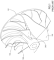
Figure 1 is a perspective view of an impeller of a centrifugal compressor according to the prior art, -
Figure 2 is a perspective view of a motor vehicle according to the invention, -
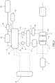
Figure 3 is a block diagram of an electric power generation assembly of the motor vehicle including a fuel cell and a centrifugal compressor to compress a reagent supplied to the fuel cell, -
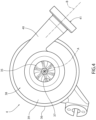
Figure 4 is a front view of the centrifugal compressor, i.e. a view across a plane perpendicular to an inlet axis of the compressor, -
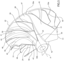
Figure 5 is a perspective view, on an enlarged scale, of an impeller of the compressor inFigure 4 , -
Figure 6 is a perspective view representing a comparison between the impeller inFigure 5 and the known impeller inFigure 1 , -
Figure 7 is a front view to show, from the front, the comparison between the impellers inFigure 5 andFigure 1 , and -
Figure 8 is a schematic representation of sound reproduction equipment for reproducing a sound produced by the operation of the compressor inFigure 4 . - In
Figure 2 , the reference number 1 is used to indicate, as a whole, a vehicle, specifically a motor vehicle, in particular a sports or race car. - The motor vehicle 1 comprises a
body 2 defining an internal passenger compartment or cabin to accommodate at least one driver and, optionally, one or more passengers. - The motor vehicle 1 also comprises at least one
fuel cell 10 and asupply assembly 11 configured to supply thefuel cell 10. - The
fuel cell 10 comprises, in particular - a fuel circuit with an
inlet point 14 to receive a fuel as input and anoutlet point 15 to discharge the unused fuel, - a reagent circuit comprising an
inlet point 18 to receive a suitable reagent as input to react with the fuel generating an electric current and a waste substance, as well as anoutlet point 19 to discharge the unused reagent and the waste substance, and - a coolant circuit comprising an
inlet point 22 to receive a cool coolant as input to remove heat and anoutlet point 23 to discharge the coolant heated by the heat removed. - In the operation of the
fuel cell 10, a part of the fuel circulating in the fuel circuit is used since subject to an electrochemical reaction. - The electrochemical reaction occurs with a part of the reagent circulating in the reagent circuit and through an electrolyte of the
fuel cell 10. - The electrochemical reaction entails the splitting of the fuel into positive ions and electrons.
- The positive ions cross the electrolyte binding with the reagent, thus forming the waste substance with it.
- In addition, the electrolyte prevents the passage of electrons at the same time.
- The latter bypass the electrolyte through an electric circuit of the
fuel cell 10, thus forming an electric current. - The reagent part that actually reacts with the fuel is used up through the formation of the waste substance.
- In detail, the reagent is a compressible fluid, in particular in the gaseous state for environmental temperature and pressure conditions.
- The electrolyte could comprise, for example, a proton exchange membrane arranged between the fuel circuit and the reagent circuit so as to enter in contact, at the same time, with the fuel and the reagent at its respective, opposite surfaces.
- For example, the fuel comprises or is defined by hydrogen.
- In addition, for example, the reagent comprises or is defined by oxygen. The oxygen could simply be part of the air surrounding the motor vehicle 1. Therefore, the reagent could also be considered as comprising or being defined by air, more generally.
- In addition, for example, the coolant could comprise or be defined by water.
- If the fuel and reagent were, respectively, hydrogen and oxygen or air, the waste substance would comprise or be defined by water, although, in particular, not the same water as the coolant.
- In any case, in general, the operation of the
fuel cell 10 is known, so it will not be described in further detail. - The
supply assembly 11 supplies thefuel cell 10 with the fuel and the reagent. More precisely, thesupply assembly 11 supplies theinlet points - The reagent will react with the fuel in the
fuel cell 10 generating an electric current and, thus, electric power. - The
supply assembly 11 comprises acentrifugal compressor 4 configured to compress the reagent. - The
compressor 4 retrieves the reagent, in this case, from the environment outside the motor vehicle 1. In particular, the reagent retrieved by thecompressor 4, i.e. at least part of the air outside the motor vehicle 1, passes through anair filter 5 to purify the outside air. - Thus, the
compressor 4 compresses the reagent and sends it to thefuel cell 10 or, more precisely, to theinlet point 18. - The reagent compressed by the
compressor 4 preferably passes through anintercooler 6, which is configured to exchange heat between the compressed reagent and the outside environment, so that the compressed reagent cools down, transferring heat to the outside environment. - More preferably, the motor vehicle 1 comprises a
humidifier 7, arranged, in particular, between theintercooler 6 and thefuel cell 10, to humidify the compressed reagent before the latter reaches thefuel cell 10. - For example, the compressed reagent enters the
fuel cell 10 or, more precisely, theinlet point 18 via avalve device 8 configured to adjust a flow of reagent towards thefuel cell 10. In particular, thevalve device 8 is arranged between thehumidifier 7 and thefuel cell 10. - Optionally, the reagent and the waste substance leave the
fuel cell 10 or, more precisely, theoutlet point 19 via anothervalve device 9 configured to adjust a discharge flow of reagent from thefuel cell 10. - The reagent and the waste substance can pass through the
humidifier 7. In particular, thehumidifier 7 is configured to transfer the humidity of the waste substance to the compressed reagent from thecompressor 4 and directly towards thefuel cell 10 or, more precisely, towards theinlet point 18. - In addition, the motor vehicle 1 comprises a
separation device 25 configured to separate the reagent and waste substance leaving thefuel cell 10. Theseparation device 25 is preferably arranged downstream of thehumidifier 7. - The waste substance separated using the
separation device 25 reaches an outlet towards the outside environment. - The
supply assembly 11 comprises aturbine 26 configured to receive a flow of reagent leaving or discharged from thefuel cell 10, i.e., in detail, the reagent separated using theseparation device 25, and to generate mechanical power by the flow of reagent. - The mechanical power produced by the
turbine 26 is used by thecompressor 4 to compress the reagent retrieved by thatcompressor 4. Therefore, theturbine 26 could be coupled to thecompressor 4 so as to supply the mechanical power produced to thecompressor 4. - Optionally, an electric
motor generator unit 27 is placed between theturbine 26 and thecompressor 4. The electricmotor generator unit 27 is coupled to theturbine 26 and to thecompressor 4 to transform the mechanical power produced by theturbine 26 into electric power and to drive thecompressor 4 using electric power. Alternatively, themotor generator unit 27 and theturbine 26 may be coupled to thecompressor 4 in parallel so as to drive thecompressor 4 according to a parallel architecture. - The
compressor 4, themotor generator unit 27, and theturbine 26 are, therefore, part of a turbocharger assembly. - The
supply assembly 11 also comprises a fuel supply line, in turn comprising atank 28 to hold the fuel, aninjection device 29 configured to inject the fuel into thefuel cell 10, and an optional recirculation device 30 (for example a pump or fan) configured to redirect the fuel leaving thefuel cell 10, since not used by the same, to thetank 28. - The coolant preferably circulates from the
outlet point 23 to theinlet point 22 through a cooling line passing through a radiator 31 of the refrigeration line. The radiator 31 is configured to exchange heat between the coolant and the outside environment, so that the coolant cools down, transferring heat to the outside environment. The circulation of the coolant from theoutlet point 23 to theinlet point 22 is, preferably, in a closed loop and occurs by means of a pump that is not illustrated. - The motor vehicle 1 also comprises at least one electric
power storage device 32, for example a battery, configured to store the electric power generated by thefuel cell 10. - In addition, the motor vehicle 1 comprises an electric motor that is not illustrated but is configured to propel the motor vehicle 1. The electric motor is connected to the
device 32 to be supplied with stored electric power. - For clarity, any component schematically depicted in
Figure 3 may considered independently of the others and as part of the motor vehicle 1. - Passing to
Figure 4 , thecompressor 4 comprises animpeller 35. - More specifically, the
compressor 4 also comprises anexternal casing 36 that houses theimpeller 35. - The
impeller 35 rotates with respect to thecasing 36 around an inlet axis A, in detail, a straight one. - The
casing 36 has aninlet opening 37 at the axis A; in particular, the inlet opening is defined by a through hole of thecasing 36 along the axis A. - The reagent enters the
compressor 4 via theopening 37, thus reaching theimpeller 35. - In addition, the
casing 36 defines astator channel 38 inside with at least oneportion 39 that extends substantially in a circumferential direction around the axis A, as well as around theimpeller 35 in a position radially more external than theimpeller 35, and aportion 40 extending tangentially from theportion 39 along a tangential axis B and terminating with theoutlet opening 41, in particular defined by a through hole of thecasing 36 along the axis B. - The rotation of the
impeller 35 around the axis A radially pushes the reagent axially entering through theinlet opening 37, thus increasing its kinetic energy. - The reagent is thus compressed crossing the
stator channel 38 until it goes out through theoutlet opening 41. Therefore, thestator channel 38 has a shape configured to convert the kinetic energy of the reagent into an increase in pressure of the reagent. - The
impeller 35 comprises ashaft portion 42 extending along the axis A and acircumferential edge 43 extending ringwise, in particular circular, around the axis A (in detail, across a plane orthogonal to the axis A). - In addition, the
impeller 35 comprises a connectingportion 44 extending from theshaft portion 42 to thecircumferential edge 43. - More specifically, both the
shaft portion 42 and the connectingportion 44 are axially symmetrical to the axis A and coaxial to each other. - In particular, along the axis A, the
shaft portion 42 maintains a constant radial extension (i.e., a radius) with respect to the axis A, while the connectingportion 44 has a radial extension that steadily grows, more specifically gradually, starting from theshaft portion 42 until it meets thecircumferential edge 43, thus radially connecting theshaft portion 42 with thecircumferential edge 43. - Therefore, the connecting
portion 44 is substantially radial, i.e. it has a radial extension that goes from the lateral, external surface of theshaft portion 42 to thecircumferential edge 43. - The connecting
portion 44 preferably forms a single piece with theshaft portion 42 and thecircumferential edge 43. More generally, thewhole impeller 35 is preferably made of a single piece. - The
impeller 35 also comprisesfirst blades 45 and second 46 blades that project from the connectingportion 44. Each of theblades 46 is arranged between twocorresponding blades 45, in particular angularly arranged around the axis A between the two correspondingblades 45 so as to form two respectiveradial flow channels 47 for the reagent. - In practice, the rotation of the
impeller 35 around the axis A pushes the reagent to radially flow, i.e. in a centrifugal manner, along thechannels 47. Thus, each of thechannels 47 delimited by one of theblades 46 and one of theother blades 45 defines a centrifugal path, i.e. with at least one radial component, for the reagent axially entering along the axis A. - Optionally, the
impeller 35 comprises splitter baffles 48, each of which is protruding from the connectingportion 44 and is arranged to further divide in two a portion (or, better, only a portion) of a corresponding one of thechannels 47. - In particular, the
impeller 35 comprises asplitter baffle 48 for each of thechannels 47. - The splitter baffles 48 preferably extend only to the connecting
portion 44, no further than to meet thecircumferential edge 43. - In addition, the splitter baffles 48 preferably extend to the
circumferential edge 43, i.e. they terminate at thecircumferential edge 43. - The splitter baffles 48 extend along the radial path defined by the
channels 47, in particular along a terminal section of the radial path, considering that the radial path starts with an end closer to theshaft portion 42 than to thecircumferential edge 43 and terminates with an end closer to thecircumferential edge 43 than to theshaft portion 42. - The sub-portions divided by each of the splitter baffles 48 are adjacent to each other along a circumferential direction with respect to the axis A.
- In practice, each of the splitter baffles 48 is arranged in the middle of the corresponding
channel 47, thus dividing thechannel 47 in half, with the adjacent halves along the circumferential direction. - The splitter baffles 48 should not be confused with the
blades blades compressor 4 and for avoiding the so-called "choked flow" phenomenon at the leading edges of the main blades, here defined by theblades - For example, the splitter baffles 48 have an axial extension (along the axis A), in particular starting from the
circumferential edge 43, less than or equal to half, or more generally three quarters, of the axial extension of theimpeller 35. On the other hand, the main blades, here defined by theblades circumferential edge 43, greater than half, or more generally three quarters, of the axial extension of theimpeller 35. - The
blades respective bases 50 that extend at least to the connectingportion 44, although they may also extend to theshaft portion 42. - The
blades bases 50 with a configuration overhanging the connectingportion 44 and, potentially, theshaft portion 42 until they terminate withfree ends 51 opposite thebases 50. - The
bases 50 extend along respective directions or curvilinear abscissae that have the same shape. This means that there is at least one rigid rotational-translation that enables the perfect overlapping of two,separate bases 50. In other words, the curvilinear abscissae are, ideally, able to be overlapped, even if positioned separately on theimpeller 35. - More specifically, the curvilinear abscissae are not unlimited, but extend between two opposite ends, thus defining respective curvilinear segments.
- The
bases 50 or the corresponding curvilinear abscissae are located on theimpeller 35 uniformly distributed according to at least one angular period around the axis A. This means that the curvilinear abscissae have corresponding points (for example, even just one point for each curvilinear abscissae) distributed around the axis A, for example along a circular direction on a plane perpendicular to the axis A, according to said angular period. The points are all, in particular, positioned in the same position with the identical shape of the corresponding curvilinear abscissae. In other words, the points all have the same coordinate along the corresponding curvilinear abscissae. For example, the points coincide with ends of the curvilinear abscissae, in particular those closer to thecircumferential edge 43 than to theshaft portion 42. - In the embodiment illustrated, the points are right on the
circumferential edge 43, which extends between the other things on the plane perpendicular to the axis A in a circular way. - The angular period can also be defined as a step or angular step of the blades from the
blades impeller 35. - The
bases 50 of theblades 45 have respective first lengths (clearly along or according to the corresponding curvilinear abscissae) that are equal. Similarly, thebases 50 of theblades 46 have respective second lengths (again along or according to the corresponding curvilinear abscissae) that are equal. - The second lengths are shorter or smaller than the first lengths.
- In particular, the
bases 50 with the first lengths occupy the whole extension of the corresponding curvilinear segments or curvilinear abscissae. Therefore, thebases 50 with the second lengths are basically a little shorter than those with the first lengths, though extending along curvilinear segments or curvilinear abscissae equal to those along which theother bases 50 extend. - In any case, all the
bases 50 preferably havecorresponding ends 50b at theshaft portion 42. - In addition, all the
bases 50 preferably extend starting from thecircumferential edge 43, i.e. they have ends 50a at thecircumferential edge 43. - Similarly to the
bases 50, the free ends 51 extend along respective curvilinear abscissae that have the same shapes. Similarly, again, to thebases 50, the lengths of the free ends 51 of theblades 46 are shorter than the lengths of the free ends 51 of theblades 45. - More generally, the
bases 50 or the free ends 51 may, more generally, be considered as specific profiles of theblades bases 50 or the free ends 51, which are, in particular, the two opposite, end profiles of theblades blades blades - The
blades 45 are all the same, like theother blades 46, although distributed on theimpeller 35 with separate positions. - The slight difference between the
blades 45 and theother blades 46 is clearly visible in the comparison ofFigures 6 and7 , where theimpeller 35 is compared with animpeller 101 according to the prior art illustrated inFigure 1 . InFigures 6 ,7 , the difference between theimpellers impeller 101 hasmain blades 102 that are all the same. - In
Figure 7 , the leadingedges 24 of theblades blades 102 are projected onto the plane perpendicular to the axis A. - Conveniently, the leading
edges 24 of theblades portion 44 according to embodiments not illustrated) that are substantially the same. Here, the term "substantially" means that the leading angles or pitches may differ within a range of -15° to 15°, more preferably -10° to 10°. - The projections of the
leading edges 24 on the plane perpendicular to the axis A are preferably radial or extend radially with respect to the axis A, as can be seen inFigure 7 . - With the configuration of the
impeller 101, i.e. with sixblades 102 that are all the same, the periodicity of theimpeller 101 is six. - In general, the periodicity of an impeller of a generic centrifugal compressor influences the sound produced by the same generic centrifugal compressor in use.
- More specifically, the sound will have a fundamental frequency proportional to the angular rotation speed of the impeller according to a factor of proportionality equal to the periodicity of the impeller. The more significant frequencies of sound will generally be multiples of the fundamental frequency.
- Thus, the presence of the
blades bases 50 ensures that the periodicity of theimpeller 35 is halved, is specifically 3, with respect to that of theimpeller 101. - Therefore, the sound spectrum of the
compressor 4 will be enriched with respect to a known compressor, in particular with multiples of the half of the fundamental frequency. - With this enrichment, the sound spectrum will have more significant frequencies or, better, double the significant frequencies, in particular equal to the number of significant frequencies of a thermal engine.
- On the other hand, the natural frequencies of the sound produced by the operation of the
compressor 4 will remain much higher than those of a sound produced by a thermal engine. - Therefore, the motor vehicle 1 advantageously comprises (
Figure 8 ) asensor 55 configured to pick up a sound produced by the operation of thecompressor 4 and to generate a sound signal containing at least information on the frequencies of the sound produced. - The
sensor 55 could be coupled to thecompressor 4; in particular, thesensor 55 is fixed to thecasing 36. - The
sensor 55 can be arranged at theinlet opening 37. - For example, the
sensor 55 is configured to measure the pressure of sound waves or a quantity indicating the same pressure. Therefore, the sound signal could indicate pressure; the frequencies of the sound signal will substantially be the same as those of the sound produced by thecompressor 4. - In detail, the
sensor 55 could be a microphone. - In addition, the motor vehicle 1 comprises a
processing device 56, for example a control unit comprising, in particular, an electronic calculating unit. Theprocessing device 56 is configured to process the sound signal by transposing its frequencies downward. - In other words, the
processing device 56 extracts the information on the frequencies, transposes the frequencies downwards, and generates a new sound signal to replace the previous one, i.e., it updates the sound signal introducing information on the transposed frequencies to the new signal or the updated signal. Therefore, the updated signal carries or contains the information on the frequencies transposed. - In practice, the
processing device 56 conditions the sound signal applying a pitch-shift technique to the sound signal, thus producing an updated or conditioned sound signal. - In particular, the transposition of the frequencies occurs with a constant transposition gain. For example, each of the frequencies is transposed by at least three octaves lower, preferably up to a maximum of four octaves lower.
- The updated sound signal is preferably also amplified, with respect to the original sound signal, by the
processing device 56. - In more detail, the amplification of the sound signal comprises an increase in the amplitudes of the sound signal associated with the transposed frequencies.
- In addition, the motor vehicle 1 comprises a
speaker device 57 configured to receive the updated or processed sound signal from theprocessing device 56 and to reproduce a transposed sound corresponding to the signal received. - Therefore, the transposed sound will have the transposed frequencies. In addition, if the original sound signal is amplified, the transposed sound reproduced by the
speaker device 57 will be amplified, i.e. with greater amplitudes, i.e. with a greater volume or intensity, with respect to the sound originally produced by the operation of thecompressor 4. - The
speaker device 57 is preferably configured to reproduce the transposed sound inside the motor vehicle 1 passenger compartment. - From the above, the advantages of the motor vehicle 1 are clear.
- Although the motor vehicle 1 does not have a thermal or internal combustion engine, the sound of the latter is, in any case, similarly obtained from the
supply assembly 11, i.e. from thecompressor 4. - The
compressor 4 is, in any case, an important component of thesupply assembly 11, so that the sounds of the fossil fuel vehicle are obtained without including additional machines, beyond those already necessary for the overall operation of thefuel cell 10 and, therefore, of the motor vehicle 1. - In addition, the technical field of fuel cells is an extremely attractive opportunity due to its substantially non-existent environmental impact and high efficiency.
- Finally, it is clear that changes may be made to the motor vehicle 1 according to the invention, and variations produced thereto, that, in any case, do not depart from the scope of protection defined by the claims.
- In particular, each of the details schematically represented in the figures is independent of the other details and is, specifically, devised to resolve specific technical problems in isolation with respect to the other details.
- In addition, the number or shape of each of the components illustrated could be different to what is described and shown in the figures.
Claims (10)
- A motor vehicle (1) comprising at least one fuel cell (10) and a supply assembly (11) configured to supply the fuel cell (10) with a fuel and a compressible reagent for reacting with the fuel in the fuel cell (10) with generation of electric power,wherein the supply assembly (11) comprises a centrifugal compressor (4) configured to compress the reagent and comprising an impeller (35) having in turn- a shaft portion (42) extending along an inlet axis (A),- a circumferential edge (43) extending ringwise around the inlet axis (A),- a connecting portion (44) extending from the shaft portion (42) to the circumferential edge (43),- first and second blades (45, 46) projecting from the connecting portion (44), of which each of the second blades (46) is arranged between two corresponding first blades (45) to form two respective radial flow channels (47) for the reagent, and- optional splitter baffles (48), each of which is protruding from the connecting portion (44) and arranged to further divide a portion of a corresponding one of the radial flow channels (47) in two parts,the first and second blades (45, 46) having respective profiles (50, 51) along respective curvilinear abscissae with shapes equal to each other and located uniformly distributed according to a period or angular step around the inlet axis (A),wherein the profiles (50, 51) of the first blades (45) and second blades (46) have first lengths equal to each other and second lengths equal to each other, respectively,characterized in that the second lengths are smaller than the first lengths.
- The motor vehicle according to claim 1, wherein the profiles (50, 51) are respectively defined by bases (50) extending at least at the connecting portion (44) and/or by free ends (51) opposite the bases (50).
- The motor vehicle according to claim 1 or 2, wherein the profiles (50, 51) all extend from the circumferential edge (43) along the respective curvilinear abscissae.
- The motor vehicle according to any one of the preceding claims, wherein the profiles (50, 51) have respective ends (50b) at the shaft portion (42).
- The motor vehicle according to any one of the preceding claims, wherein the first and second blades (45, 46) have respective leading edges (24) respectively forming with the shaft portion (42) or with the connecting portion (44) substantially equal angles of attack with each other.
- The motor vehicle according to any of the preceding claims, further comprising- a sensor (55) configured to pick up a sound produced by an operation of the centrifugal compressor (4) and to generate a sound signal containing information about the frequencies of said sound,- a processing device (56) configured to process the sound signal by transposing its frequencies downward, and- a speaker device (57) configured to receive the sound signal processed by the processing device (56) and to reproduce a transposed sound corresponding to the sound signal processed by the processing device (56).
- The motor vehicle according to claim 6, wherein the processing device (56) is configured to transpose the frequencies of the sound signal with a constant transposition gain.
- The motor vehicle according to claim 6 or 7, wherein the processing device (56) is configured to transpose the frequencies of the sound signal at least three octaves down, preferably up to a maximum of four octaves down.
- The motor vehicle according to any one of claims 6 to 8, wherein the processing device (56) is configured to amplify the sound signal so that the transposed sound reproduced by the speaker device (57) is amplified relative to the sound produced by the operation of the centrifugal compressor (4).
- The motor vehicle according to any one of claims 6 to 9, wherein the speaker device (57) is configured to reproduce the transposed sound within a passenger compartment of the motor vehicle.
Applications Claiming Priority (1)
| Application Number | Priority Date | Filing Date | Title |
|---|---|---|---|
| IT102023000021351A IT202300021351A1 (en) | 2023-10-13 | 2023-10-13 | FUEL CELL-POWERED MOTOR VEHICLE WITH IMPROVED SOUND EMISSION |
Publications (1)
| Publication Number | Publication Date |
|---|---|
| EP4538539A1 true EP4538539A1 (en) | 2025-04-16 |
Family
ID=89427381
Family Applications (1)
| Application Number | Title | Priority Date | Filing Date |
|---|---|---|---|
| EP24206074.7A Pending EP4538539A1 (en) | 2023-10-13 | 2024-10-11 | Motor vehicle provided with fuel cells with an improved sound emission |
Country Status (4)
| Country | Link |
|---|---|
| US (1) | US20250121770A1 (en) |
| EP (1) | EP4538539A1 (en) |
| CN (1) | CN119825748A (en) |
| IT (1) | IT202300021351A1 (en) |
Citations (4)
| Publication number | Priority date | Publication date | Assignee | Title |
|---|---|---|---|---|
| US8754762B2 (en) * | 2010-11-29 | 2014-06-17 | Hyundai Motor Company | Apparatus for generating operating sound of vehicle |
| CN110230609B (en) * | 2018-03-05 | 2020-12-15 | 三菱重工业株式会社 | Impeller and centrifugal compressor having the same |
| US20210295817A1 (en) * | 2020-03-18 | 2021-09-23 | Harman International Industries, Incorporated | Motor noise masking |
| GB2611561A (en) * | 2021-10-08 | 2023-04-12 | Cummins Ltd | Compressor impeller |
-
2023
- 2023-10-13 IT IT102023000021351A patent/IT202300021351A1/en unknown
-
2024
- 2024-09-30 US US18/902,613 patent/US20250121770A1/en active Pending
- 2024-10-10 CN CN202411407261.5A patent/CN119825748A/en active Pending
- 2024-10-11 EP EP24206074.7A patent/EP4538539A1/en active Pending
Patent Citations (4)
| Publication number | Priority date | Publication date | Assignee | Title |
|---|---|---|---|---|
| US8754762B2 (en) * | 2010-11-29 | 2014-06-17 | Hyundai Motor Company | Apparatus for generating operating sound of vehicle |
| CN110230609B (en) * | 2018-03-05 | 2020-12-15 | 三菱重工业株式会社 | Impeller and centrifugal compressor having the same |
| US20210295817A1 (en) * | 2020-03-18 | 2021-09-23 | Harman International Industries, Incorporated | Motor noise masking |
| GB2611561A (en) * | 2021-10-08 | 2023-04-12 | Cummins Ltd | Compressor impeller |
Also Published As
| Publication number | Publication date |
|---|---|
| CN119825748A (en) | 2025-04-15 |
| IT202300021351A1 (en) | 2025-04-13 |
| US20250121770A1 (en) | 2025-04-17 |
Similar Documents
| Publication | Publication Date | Title |
|---|---|---|
| US6028369A (en) | Engine-operated generator | |
| US20230399976A1 (en) | Recirculation fan turbocharger assembly and fuel cell system | |
| US10087953B2 (en) | Air blower for fuel cell vehicle | |
| US20050008912A1 (en) | Cooling of air-cooled fuel cell system | |
| CN110534771A (en) | Apparatus for air supply to fuel cells, preferably hydrogen-operated fuel cells | |
| MX9800660A (en) | Motor-assisted variable geometry turbocharging system. | |
| WO2003040567A1 (en) | Two stage electrically powered compressor | |
| CN212935650U (en) | Cooling structure of fuel cell centrifugal air compressor | |
| EP4538539A1 (en) | Motor vehicle provided with fuel cells with an improved sound emission | |
| EP1498971A2 (en) | Cooling of air-cooled fuel cell system | |
| KR20190134497A (en) | Device for the air supply of a fuel cell | |
| CN114556754A (en) | Fluid machine and method for operating a fluid machine | |
| Sugawara et al. | Development of motorized turbo compressor for clarity fuel cell | |
| DE59712998D1 (en) | Gas turbine arrangement for air conditioning | |
| KR20210120275A (en) | Air compressor for car | |
| JP2008295192A (en) | Rotating electric machine | |
| CN118282086A (en) | Cooling structure of wind turbine generator and wind turbine generator set | |
| JP2007159277A (en) | High-speed rotating machine cooling structure | |
| JP7582173B2 (en) | Centrifugal Compressor | |
| KR101289800B1 (en) | Permanent magnetic motor and fluid charger comprising the same | |
| CN215444259U (en) | System for supplying operating gas to a drive of a motor vehicle | |
| GB1428929A (en) | Supercharger system for an internal combustion engine | |
| JP2003314296A (en) | Hybrid system | |
| CN224049425U (en) | Compressor inter-stage diffusion flow guiding structure, compressor and fuel cell system | |
| CN223424263U (en) | A wind-guiding and speed-increasing airflow mixing generator |
Legal Events
| Date | Code | Title | Description |
|---|---|---|---|
| PUAI | Public reference made under article 153(3) epc to a published international application that has entered the european phase |
Free format text: ORIGINAL CODE: 0009012 |
|
| STAA | Information on the status of an ep patent application or granted ep patent |
Free format text: STATUS: THE APPLICATION HAS BEEN PUBLISHED |
|
| AK | Designated contracting states |
Kind code of ref document: A1 Designated state(s): AL AT BE BG CH CY CZ DE DK EE ES FI FR GB GR HR HU IE IS IT LI LT LU LV MC ME MK MT NL NO PL PT RO RS SE SI SK SM TR |
|
| STAA | Information on the status of an ep patent application or granted ep patent |
Free format text: STATUS: REQUEST FOR EXAMINATION WAS MADE |
|
| 17P | Request for examination filed |
Effective date: 20251009 |