EP4538521A1 - Prechamber-type engine - Google Patents
Prechamber-type engine Download PDFInfo
- Publication number
- EP4538521A1 EP4538521A1 EP23854823.4A EP23854823A EP4538521A1 EP 4538521 A1 EP4538521 A1 EP 4538521A1 EP 23854823 A EP23854823 A EP 23854823A EP 4538521 A1 EP4538521 A1 EP 4538521A1
- Authority
- EP
- European Patent Office
- Prior art keywords
- prechamber
- combustion chamber
- cylinder
- type engine
- piston
- Prior art date
- Legal status (The legal status is an assumption and is not a legal conclusion. Google has not performed a legal analysis and makes no representation as to the accuracy of the status listed.)
- Pending
Links
Images



Classifications
-
- F—MECHANICAL ENGINEERING; LIGHTING; HEATING; WEAPONS; BLASTING
- F02—COMBUSTION ENGINES; HOT-GAS OR COMBUSTION-PRODUCT ENGINE PLANTS
- F02B—INTERNAL-COMBUSTION PISTON ENGINES; COMBUSTION ENGINES IN GENERAL
- F02B19/00—Engines characterised by precombustion chambers
- F02B19/08—Engines characterised by precombustion chambers the chamber being of air-swirl type
-
- F—MECHANICAL ENGINEERING; LIGHTING; HEATING; WEAPONS; BLASTING
- F02—COMBUSTION ENGINES; HOT-GAS OR COMBUSTION-PRODUCT ENGINE PLANTS
- F02B—INTERNAL-COMBUSTION PISTON ENGINES; COMBUSTION ENGINES IN GENERAL
- F02B19/00—Engines characterised by precombustion chambers
- F02B19/10—Engines characterised by precombustion chambers with fuel introduced partly into pre-combustion chamber, and partly into cylinder
- F02B19/1004—Engines characterised by precombustion chambers with fuel introduced partly into pre-combustion chamber, and partly into cylinder details of combustion chamber, e.g. mounting arrangements
- F02B19/1014—Engines characterised by precombustion chambers with fuel introduced partly into pre-combustion chamber, and partly into cylinder details of combustion chamber, e.g. mounting arrangements design parameters, e.g. volume, torch passage cross sectional area, length, orientation, or the like
-
- F—MECHANICAL ENGINEERING; LIGHTING; HEATING; WEAPONS; BLASTING
- F02—COMBUSTION ENGINES; HOT-GAS OR COMBUSTION-PRODUCT ENGINE PLANTS
- F02B—INTERNAL-COMBUSTION PISTON ENGINES; COMBUSTION ENGINES IN GENERAL
- F02B19/00—Engines characterised by precombustion chambers
- F02B19/10—Engines characterised by precombustion chambers with fuel introduced partly into pre-combustion chamber, and partly into cylinder
- F02B19/1019—Engines characterised by precombustion chambers with fuel introduced partly into pre-combustion chamber, and partly into cylinder with only one pre-combustion chamber
- F02B19/1023—Engines characterised by precombustion chambers with fuel introduced partly into pre-combustion chamber, and partly into cylinder with only one pre-combustion chamber pre-combustion chamber and cylinder being fed with fuel-air mixture(s)
- F02B19/1071—Engines characterised by precombustion chambers with fuel introduced partly into pre-combustion chamber, and partly into cylinder with only one pre-combustion chamber pre-combustion chamber and cylinder being fed with fuel-air mixture(s) pre-combustion chamber having only one orifice,(i.e. an orifice by means of which it communicates with the cylinder); the intake system comprising two distinct intake conduits
-
- F—MECHANICAL ENGINEERING; LIGHTING; HEATING; WEAPONS; BLASTING
- F02—COMBUSTION ENGINES; HOT-GAS OR COMBUSTION-PRODUCT ENGINE PLANTS
- F02B—INTERNAL-COMBUSTION PISTON ENGINES; COMBUSTION ENGINES IN GENERAL
- F02B19/00—Engines characterised by precombustion chambers
- F02B19/10—Engines characterised by precombustion chambers with fuel introduced partly into pre-combustion chamber, and partly into cylinder
- F02B19/1019—Engines characterised by precombustion chambers with fuel introduced partly into pre-combustion chamber, and partly into cylinder with only one pre-combustion chamber
- F02B19/108—Engines characterised by precombustion chambers with fuel introduced partly into pre-combustion chamber, and partly into cylinder with only one pre-combustion chamber with fuel injection at least into pre-combustion chamber, i.e. injector mounted directly in the pre-combustion chamber
-
- F—MECHANICAL ENGINEERING; LIGHTING; HEATING; WEAPONS; BLASTING
- F02—COMBUSTION ENGINES; HOT-GAS OR COMBUSTION-PRODUCT ENGINE PLANTS
- F02B—INTERNAL-COMBUSTION PISTON ENGINES; COMBUSTION ENGINES IN GENERAL
- F02B19/00—Engines characterised by precombustion chambers
- F02B19/14—Engines characterised by precombustion chambers with compression ignition
-
- F—MECHANICAL ENGINEERING; LIGHTING; HEATING; WEAPONS; BLASTING
- F02—COMBUSTION ENGINES; HOT-GAS OR COMBUSTION-PRODUCT ENGINE PLANTS
- F02F—CYLINDERS, PISTONS OR CASINGS, FOR COMBUSTION ENGINES; ARRANGEMENTS OF SEALINGS IN COMBUSTION ENGINES
- F02F3/00—Pistons
- F02F3/26—Pistons having combustion chamber in piston head
-
- Y—GENERAL TAGGING OF NEW TECHNOLOGICAL DEVELOPMENTS; GENERAL TAGGING OF CROSS-SECTIONAL TECHNOLOGIES SPANNING OVER SEVERAL SECTIONS OF THE IPC; TECHNICAL SUBJECTS COVERED BY FORMER USPC CROSS-REFERENCE ART COLLECTIONS [XRACs] AND DIGESTS
- Y02—TECHNOLOGIES OR APPLICATIONS FOR MITIGATION OR ADAPTATION AGAINST CLIMATE CHANGE
- Y02T—CLIMATE CHANGE MITIGATION TECHNOLOGIES RELATED TO TRANSPORTATION
- Y02T10/00—Road transport of goods or passengers
- Y02T10/10—Internal combustion engine [ICE] based vehicles
- Y02T10/12—Improving ICE efficiencies
Definitions
- the present disclosure relates to a prechamber-type engine.
- a prechamber-type engine (swirl chamber-type engine) is used as one type of engines.
- the prechamber-type engine includes a main combustion chamber defined between a piston, a cylinder, and a cylinder head, and a pre-combustion chamber that is communicated with the main combustion chamber through a nozzle hole.
- the combustion gas (prechamber gas) generated in the pre-combustion chamber is jetted into the main combustion chamber through the nozzle hole due to the volume change of the main combustion chamber caused by the piston movement.
- PTL 1 discloses a prechamber-type engine that is intended to promote diffusion combustion in a combustion chamber.
- this prechamber-type engine by making the shape of the piston cavity of the top surface of the piston shallower from the vicinity of the nozzle hole outlet toward the center direction of the cylinder, the generation of the mixed gas in the main combustion chamber is promoted, and the diffusion combustion in the combustion chamber is promoted.
- the piston cavity is provided so as to surround the main chamber-side opening of the nozzle hole in order to maintain a high flow coefficient at all crank angles. That is, the main chamber-side opening and the peripheral edge of the piston cavity are disposed so as not to overlap with each other in the plan view. Therefore, in the configuration of the related art shown in PTL 1, there is a problem in that, at a time when the flow velocity of the nozzle hole is increased, the gas flow from the pre-combustion chamber to the main combustion chamber is peeled off, so that it is not possible to form a strong flow.
- the present disclosure has been made in view of the above-mentioned problems, and an object of the present disclosure is to provide a prechamber-type engine capable of suppressing peeling of a flow of prechamber gas from a pre-combustion chamber to a main combustion chamber and increasing the output of the engine by forming a strong flow.
- a prechamber-type engine includes a cylinder and a cylinder head, and a piston that defines a main combustion chamber between the cylinder and the cylinder head, in which a pre-combustion chamber that communicates with the main combustion chamber through a nozzle hole is defined inside the cylinder head, the nozzle hole extends from a prechamber-side opening toward a main chamber-side opening such that a distance between a center line of the nozzle hole and a central axis line of the cylinder is reduced, a top surface of the piston has a concave piston cavity, and in a cross-sectional view in which the central axis line of the cylinder and a center of the main chamber-side opening are present, a first end on a side far from the central axis line of the cylinder in a peripheral edge of the main chamber-side opening is located farther from the central axis line of the cylinder than a second end on a side close to the nozzle hole in a peripheral edge of the piston cavity
- prechamber-type engine of the present disclosure it is possible to provide a prechamber-type engine capable of suppressing the peeling of the flow of the prechamber gas from the pre-combustion chamber to the main combustion chamber and increasing the output of the engine by forming a strong flow.
- expressions representing shapes such as a quadrangular shape and a cylindrical shape not only represent shapes such as a quadrangular shape and a cylindrical shape in a geometrically strict sense, but also represent shapes including an uneven portion or a chamfered portion within a range where the same effect can be obtained.
- Fig. 1 is a schematic cross-sectional view of a prechamber-type engine according to an embodiment of the present disclosure.
- a prechamber-type engine 100 includes a cylinder 8, a cylinder head 4, and a piston 7.
- the cylinder 8 is a cylindrical member that accommodates the piston 7.
- the cylinder head 4 is disposed on an upper portion of the cylinder 8.
- the piston 7 is disposed inside the cylinder 8 so as to be reciprocally movable along a central axis line CL. Then, the main combustion chamber 1 is defined between the cylinder 8 and the cylinder head 4 and the piston 7.
- a pre-combustion chamber 2 is defined inside of the cylinder head 4 and is communicated with the main combustion chamber 1 through a nozzle hole 3.
- the nozzle hole 3 has a main chamber-side opening 31 that is an opening facing the main combustion chamber 1 and a prechamber-side opening 32 that is an opening facing the pre-combustion chamber 2, and is configured with one hole-shaped portion extending from the prechamber-side opening 32 toward the main chamber-side opening 31.
- the cylinder head 4 includes a cylinder head main body 4A and a prechamber cap 9 that defines the pre-combustion chamber 2 between the cylinder head main body 4A.
- the prechamber cap 9 includes a disk-shaped main body part 91 facing the piston 7 and the cylinder 8, and a radially extending part 92 that extends radially from an outer peripheral edge portion of the main body part 91 to be separated from the piston 7 and the cylinder 8.
- the prechamber cap 9 is fastened to the cylinder head main body 4A by a well-known method such as screwing, fitting, or bolting.
- the above-described nozzle hole 3 is formed in the main body part 91.
- the pre-combustion chamber 2 is provided on one side with respect to the central axis line CL of the cylinder 8.
- the nozzle hole 3 extends from the prechamber-side opening 32 toward the main chamber-side opening 31 so that the distance between the center line 33 of the nozzle hole 3 and the central axis line CL of the cylinder 8 is reduced.
- the first end 311' on a side far from the central axis line CL' of the cylinder 8' in the peripheral edge of the main chamber-side opening 31' is configured to be located at the same distance from the central axis line CL' of the cylinder 8' as the second end 711' on a side close to the nozzle hole 3' in the peripheral edge 71e' (refer to Fig. 6 ) of the piston cavity 71A'.
- Fig. 8 in a cross-sectional view in which the central axis line CL of the cylinder 8 and the center 31c of the main chamber-side opening 31 are present, in a case where the width of the main chamber-side opening 31 is defined as D, and the distance between the first end 311 and the second end 711 in the direction orthogonal to the central axis line CL of the cylinder 8 is defined as L, L/D ⁇ 0.1 is satisfied.
- L/D is preferably 0.2 or more, and more preferably 0.3 or more and 0.5 or less. In the embodiment shown in the drawings, L/D is about 0.4.
- the far-side wall surface 34 and the near-side wall surface 35 are configured to be straight lines. Therefore, the first tangent line 34L1 matches the tangent line 34L.
- the far-side wall surface 34 and the near-side wall surface 35 may be configured to be curved, or may be configured to be a combination of a straight line and a curve.
- the rate of the volume change of the main combustion chamber 1 is large at a predetermined angle of the crank angle of the prechamber-type engine 100 in a range of ATDC 5 to 20 degrees, that is, the flow velocity of the prechamber gas from the pre-combustion chamber 2 to the main combustion chamber 1 in the nozzle hole 3 is large.
- the first tangent line 34L1 described above passes through the second end 711 of the piston cavity 71A at a predetermined angle at which the crank angle of the prechamber-type engine 100 is in a range of ATDC 10 to 20 degrees.
- the first tangent line 34L1 passes through the second end 711 of the piston cavity 71A at a predetermined angle at which the crank angle of the prechamber-type engine 100 is in a range of ATDC 12 to 18 degrees.
- the piston cavity 71A has an R portion 71R that passes through the second end 711.
- the R portion 71R is configured with a single arc from the second end 711 to the inflection point 713.
- the R portion 71R may be configured with a plurality of arcs having different curvature radii.
- the R portion 71R may include an arc with a small curvature radius that passes through the second end 711 and an arc with a large curvature radius that passes through the inflection point 713.
- the R portion 71R has the deepest portion 714 in which the distance from the top surface 71 of the piston 7 to the piston cavity 71A is the largest.
- the deepest portion 714 is located closer to the central axis line CL of the cylinder 8 than the third end 312 of the main chamber-side opening 31.
- the piston cavity 71A has an inclined portion 71I that extends from the deepest portion 714 toward a fourth end 712 on a side far from the nozzle hole 3 in the peripheral edge 71e of the piston cavity 71A such that a distance from a top surface 71 (flat-shaped portion 71B) of the piston 7 is reduced.
- a direction passing through the central axis line CL of the cylinder 8 and the center 31c of the main chamber-side opening 31 is defined as a first direction
- a direction orthogonal to the first direction is defined as a second direction
- the piston cavity 71A having the above-described inclined portion 71I is configured to be longer in the first direction than in the second direction.
- the gas flow in the main combustion chamber 1 can be made smooth, and the generation of the mixed gas can be promoted.
- the prechamber-type engine 100 of the present disclosure it is possible to form a strong flow in the main combustion chamber 1 with respect to the piston cavity 71A configured as described above.
- the piston cavity 71A has an R portion 71R from the second end 711 to the inflection point 713, and a flat portion 71F that passes through the inflection point 713 and extends at a constant distance from the top surface 71 of the piston 7.
- An end portion of the flat portion 71F on a side far from the nozzle hole 3 forms a step portion through which the fourth end 712 passes.
- a direction passing through the central axis line CL of the cylinder 8 and the center 31c of the main chamber-side opening 31 is defined as a first direction
- a direction orthogonal to the first direction is defined as a second direction
- the piston cavity 71A is configured to be longer in the second direction than in the first direction.
- piston cavity 71A according to the second embodiment is configured such that the first direction is shorter and the second direction is longer than in the first embodiment.
- prechamber-type engine 100 of the present disclosure it is possible to form a strong flow in the main combustion chamber 1 with respect to the piston cavity 71A configured as described above.
- the piston cavity 71A has an R portion 71R that passes through the second end 711.
- the flow of the prechamber gas from the pre-combustion chamber 2 to the main combustion chamber 1 can be made smooth, and it is possible to form a strong flow from the pre-combustion chamber 2 to the main combustion chamber 1.
- the R portion 71R has the deepest portion 714 in which the distance from the top surface 71 of the piston 7 to the piston cavity 71A is the longest.
- the deepest portion 714 is located closer to the central axis line CL of the cylinder 8 than the third end 312 of the main chamber-side opening 31.
- the flow of the prechamber gas from the pre-combustion chamber 2 to the main combustion chamber 1 can be made smooth, and it is possible to form a strong flow from the pre-combustion chamber 2 to the main combustion chamber 1.
- the R portion 71R has a center on a side close to the cylinder head 4 with respect to the piston cavity 71A as a reference and is configured with an arc passing through the second end 711, and has a center on a side far from the cylinder head 4 with respect to the piston cavity 71A as a reference and is configured with an arc passing through the inflection point 713. Therefore, with such a configuration, the inflection of the piston cavity 71A at the inflection point 713 can be made smooth. Therefore, the flow of the prechamber gas from the pre-combustion chamber 2 to the main combustion chamber 1 can be made smooth, and it is possible to form a strong flow from the pre-combustion chamber 2 to the main combustion chamber 1.
- the rate of the volume change of the main combustion chamber is large in a range of 5 to 20 degrees after the top dead center of the crank angle, and the flow velocity of the prechamber gas jetted from the pre-combustion chamber to the main combustion chamber is large.
- a prechamber-type engine according (100) to still another aspect is the prechamber-type engine according to any one of (1) to (3), in which in the cross-sectional view, the piston cavity (71A) has an R portion (71R) that passes through the second end (711).
- the flow of the prechamber gas jetted from the pre-combustion chamber (2) into the main combustion chamber (1) can be made smoother, and it is possible to form a strong flow in the main combustion chamber (1).
- the gas flow in the main combustion chamber can be made smooth, and the generation of the mixed gas can be promoted.
- the prechamber-type engine of the present disclosure it is possible to form a strong flow in the main combustion chamber with respect to the piston cavity configured as described above.
- a prechamber-type engine (100) according to still another aspect is the prechamber-type engine according to (5), in which in the cross-sectional view, the piston cavity (71A) has a flat portion (71F) in which a distance from the top surface (71) of the piston (7) is constant.
Landscapes
- Engineering & Computer Science (AREA)
- Chemical & Material Sciences (AREA)
- Combustion & Propulsion (AREA)
- Mechanical Engineering (AREA)
- General Engineering & Computer Science (AREA)
- Combustion Methods Of Internal-Combustion Engines (AREA)
Abstract
Description
- The present disclosure relates to a prechamber-type engine.
- The present application claims priority based on
Japanese Patent Application No. 2022-131288 filed in Japan on August 19, 2022 - In the related art, a prechamber-type engine (swirl chamber-type engine) is used as one type of engines. The prechamber-type engine includes a main combustion chamber defined between a piston, a cylinder, and a cylinder head, and a pre-combustion chamber that is communicated with the main combustion chamber through a nozzle hole. The combustion gas (prechamber gas) generated in the pre-combustion chamber is jetted into the main combustion chamber through the nozzle hole due to the volume change of the main combustion chamber caused by the piston movement.
-
PTL 1 discloses a prechamber-type engine that is intended to promote diffusion combustion in a combustion chamber. In this prechamber-type engine, by making the shape of the piston cavity of the top surface of the piston shallower from the vicinity of the nozzle hole outlet toward the center direction of the cylinder, the generation of the mixed gas in the main combustion chamber is promoted, and the diffusion combustion in the combustion chamber is promoted. - [PTL 1]
Japanese Unexamined Patent Application Publication No. 8-93475 - However, in the configuration of the related art shown in
PTL 1, the piston cavity is provided so as to surround the main chamber-side opening of the nozzle hole in order to maintain a high flow coefficient at all crank angles. That is, the main chamber-side opening and the peripheral edge of the piston cavity are disposed so as not to overlap with each other in the plan view. Therefore, in the configuration of the related art shown inPTL 1, there is a problem in that, at a time when the flow velocity of the nozzle hole is increased, the gas flow from the pre-combustion chamber to the main combustion chamber is peeled off, so that it is not possible to form a strong flow. - The present disclosure has been made in view of the above-mentioned problems, and an object of the present disclosure is to provide a prechamber-type engine capable of suppressing peeling of a flow of prechamber gas from a pre-combustion chamber to a main combustion chamber and increasing the output of the engine by forming a strong flow.
- In order to achieve the above object, a prechamber-type engine includes a cylinder and a cylinder head, and a piston that defines a main combustion chamber between the cylinder and the cylinder head, in which a pre-combustion chamber that communicates with the main combustion chamber through a nozzle hole is defined inside the cylinder head, the nozzle hole extends from a prechamber-side opening toward a main chamber-side opening such that a distance between a center line of the nozzle hole and a central axis line of the cylinder is reduced, a top surface of the piston has a concave piston cavity, and in a cross-sectional view in which the central axis line of the cylinder and a center of the main chamber-side opening are present, a first end on a side far from the central axis line of the cylinder in a peripheral edge of the main chamber-side opening is located farther from the central axis line of the cylinder than a second end on a side close to the nozzle hole in a peripheral edge of the piston cavity.
- According to the prechamber-type engine of the present disclosure, it is possible to provide a prechamber-type engine capable of suppressing the peeling of the flow of the prechamber gas from the pre-combustion chamber to the main combustion chamber and increasing the output of the engine by forming a strong flow.
-
-
Fig. 1 is a schematic cross-sectional view of a prechamber-type engine according to an embodiment of the present disclosure. -
Fig. 2A is a cross-sectional view around a combustion chamber of the prechamber-type engine according to the embodiment of the present disclosure, and is a cross-sectional view in a case of ATDC 0 degrees. -
Fig. 2B is a cross-sectional view around the combustion chamber of the prechamber-type engine according to the embodiment of the present disclosure, and is a cross-sectional view in a case of ATDC 15 degrees. -
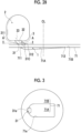
Fig. 3 is a view illustrating a positional relationship between a top surface of a piston and a nozzle hole according to the embodiment of the present disclosure, and is a view taken along a line A-A shown inFigs. 2A and2B . -
Fig. 4 is an enlarged cross-sectional view around the combustion chamber of the prechamber-type engine according to the embodiment of the present disclosure, and is a view illustrating a flow of prechamber gas that is jetted from a pre-combustion chamber to a main combustion chamber in a case ofATDC 15 degrees. -
Fig. 5A is a cross-sectional view around the combustion chamber of the prechamber-type engine according to a comparative aspect of the present disclosure, and is a cross-sectional view in a case of ATDC 0 degrees. -
Fig. 5B is a cross-sectional view around the combustion chamber of the prechamber-type engine according to the comparative aspect of the present disclosure, and is a cross-sectional view in a case of ATDC 15 degrees. -
Fig. 6 is a view illustrating a positional relationship between a top surface of the piston and the nozzle hole in the comparative aspect of the present disclosure, and is a view taken along line A-A shown inFigs. 5A and5B . -
Fig. 7 is an enlarged cross-sectional view around the combustion chamber of the prechamber-type engine according to the comparative aspect of the present disclosure, and is a view for describing the flow of the prechamber gas jetted from the pre-combustion chamber to the main combustion chamber. -
Fig. 8 is an enlarged cross-sectional view around the nozzle hole of the prechamber-type engine according to the embodiment of the present disclosure, and is an enlarged cross-sectional view in a case of ATDC 15 degrees. -
Fig. 9 is a graph showing the transition of the flow velocity of the nozzle hole and a rate of volume change of the main combustion chamber in the prechamber-type engine according to the embodiment of the present disclosure. -
Fig. 10 is a schematic cross-sectional view of the prechamber-type engine according to another embodiment of the present disclosure. -
Fig. 11 is a view illustrating a positional relationship between a top surface of a piston and a nozzle hole according to another embodiment of the present disclosure, and is a view taken along a line B-B shown inFig. 12 . -
Fig. 12 is an enlarged cross-sectional view around the nozzle hole of the prechamber-type engine according to another embodiment of the present disclosure, and is an enlarged cross-sectional view in a case of ATDC 15 degrees. - Hereinafter, some embodiments of the present disclosure will be described with reference to the accompanying drawings. However, dimensions, materials, shapes, and relative dispositions of components described as the embodiments or illustrated in the drawings are not intended to limit the scope of the present disclosure, and are merely examples for describing the present disclosure.
- For example, expressions representing relative or absolute dispositions such as "in a certain direction", "along a certain direction", "parallel", "orthogonal", "center", "concentric", or "coaxial" not only strictly represent the dispositions, but also represent a state where the dispositions are relatively displaced with a tolerance or at an angle or a distance to such an extent that the same function can be obtained.
- For example, expressions representing that things are in an equal state such as "same", "equal", and "homogeneous" not only strictly represent an equal state, but also represent a state where a difference exists with a tolerance or to such an extent that the same function can be obtained.
- For example, expressions representing shapes such as a quadrangular shape and a cylindrical shape not only represent shapes such as a quadrangular shape and a cylindrical shape in a geometrically strict sense, but also represent shapes including an uneven portion or a chamfered portion within a range where the same effect can be obtained.
- Meanwhile, expressions of "being provided with", "including", or "having" one component are not exclusive expressions excluding existence of other components.
- The same reference numerals may be assigned to the same configurations, and description thereof may be omitted.
-
Fig. 1 is a schematic cross-sectional view of a prechamber-type engine according to an embodiment of the present disclosure. - As illustrated in
Fig. 1 , a prechamber-type engine 100 according to an embodiment of the present disclosure includes acylinder 8, acylinder head 4, and apiston 7. Thecylinder 8 is a cylindrical member that accommodates thepiston 7. Thecylinder head 4 is disposed on an upper portion of thecylinder 8. Thepiston 7 is disposed inside thecylinder 8 so as to be reciprocally movable along a central axis line CL. Then, themain combustion chamber 1 is defined between thecylinder 8 and thecylinder head 4 and thepiston 7. - A
pre-combustion chamber 2 is defined inside of thecylinder head 4 and is communicated with themain combustion chamber 1 through anozzle hole 3. Thenozzle hole 3 has a main chamber-side opening 31 that is an opening facing themain combustion chamber 1 and a prechamber-side opening 32 that is an opening facing thepre-combustion chamber 2, and is configured with one hole-shaped portion extending from the prechamber-side opening 32 toward the main chamber-side opening 31. - In the embodiment shown in the drawings, the
cylinder head 4 includes a cylinder headmain body 4A and aprechamber cap 9 that defines thepre-combustion chamber 2 between the cylinder headmain body 4A. Theprechamber cap 9 includes a disk-shapedmain body part 91 facing thepiston 7 and thecylinder 8, and a radially extendingpart 92 that extends radially from an outer peripheral edge portion of themain body part 91 to be separated from thepiston 7 and thecylinder 8. Theprechamber cap 9 is fastened to the cylinder headmain body 4A by a well-known method such as screwing, fitting, or bolting. The above-describednozzle hole 3 is formed in themain body part 91. - In addition, in the embodiment not shown in the drawings, the cylinder head may be configured as a cylinder head in which a portion of the cylinder head
main body 4A shown inFig. 1 and a portion of theprechamber cap 9 are integrally formed. Such a cylinder head is manufactured, for example, by metal laminated molding. - A
fuel injector 5 is provided in thecylinder head 4. Thefuel injector 5 is configured to inject the fuel into thepre-combustion chamber 2. In addition, thecylinder head 4 is provided with aglow plug 6, and is configured to ignite the fuel injected from thefuel injector 5. The prechamber gas including the ignited combustion gas and the unburned gas is jetted from thepre-combustion chamber 2 to themain combustion chamber 1 through thenozzle hole 3 at a timing at which thepiston 7 passes through the top dead center (TDC). - The
pre-combustion chamber 2 is provided on one side with respect to the central axis line CL of thecylinder 8. Thenozzle hole 3 extends from the prechamber-side opening 32 toward the main chamber-side opening 31 so that the distance between thecenter line 33 of thenozzle hole 3 and the central axis line CL of thecylinder 8 is reduced. - In the embodiment shown in the drawings, the
center line 33 is configured to be a straight line. In the embodiment not shown in the drawings, thecenter line 33 may be configured to be curved or may be configured by combining a straight line and a curve. - A
top surface 71 of thepiston 7 has a flat-shapedportion 71B in a flat state and a recessedpiston cavity 71A that is recessed with respect to the flat-shapedportion 71B. - Next, a positional relationship between the
piston cavity 71A and thenozzle hole 3 will be described with reference toFigs. 2A ,2B, and 3 . -
Fig. 2A is a cross-sectional view around a combustion chamber of the prechamber-type engine according to the embodiment of the present disclosure, and is a cross-sectional view in a case of ATDC 0 degrees.Fig. 2B is a cross-sectional view around the combustion chamber of the prechamber-type engine according to the embodiment of the present disclosure, and is a cross-sectional view in a case ofATDC 15 degrees.Fig. 3 is a view illustrating a positional relationship between a top surface of a piston and a nozzle hole according to the embodiment of the present disclosure, and is a view taken along a line A-A shown inFigs. 2A and2B . - As shown in
Figs. 2A and2B , in the cross-sectional view in which the central axis line CL of thecylinder 8 and the center 31c of the main chamber-side opening 31 are present, aperipheral edge 31e (refer toFig. 3 ) of the main chamber-side opening 31 has afirst end 311 on a side far from the central axis line CL of thecylinder 8 and athird end 312 on a side close to the central axis line CL. Similarly, theperipheral edge 71e (refer toFig. 3 ) of thepiston cavity 71A has asecond end 711 on a side close to thenozzle hole 3 and afourth end 712 on a side far from thenozzle hole 3. Thefirst end 311 of the main chamber-side opening 31 is configured to be located farther from the central axis line CL of thecylinder 8 than thesecond end 711 of thepiston cavity 71A. - That is, as shown in
Fig. 3 , in a plan view in which thetop surface 71 of thepiston 7 is visually recognized along the extension direction of the central axis line CL of thecylinder 8, a region in which the main chamber-side opening 31 is projected onto thetop surface 71 of thepiston 7 along the extension direction of the central axis line CL of thecylinder 8 is configured to overlap with theperipheral edge 71e of thepiston cavity 71A. -
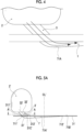
Fig. 4 is an enlarged cross-sectional view around the combustion chamber of the prechamber-type engine according to the embodiment of the present disclosure, and is a view illustrating a flow of prechamber gas that is jetted from a pre-combustion chamber to a main combustion chamber in a case ofATDC 15 degrees. As shown inFig. 9 which will be described later, a rate of the volume change of themain combustion chamber 1 is particularly large atATDC 5 to 20 degrees. According to the prechamber-type engine according to one embodiment of the present disclosure, as illustrated inFig. 4 , when the rate of the volume change of themain combustion chamber 1 is large, that is, when the flow velocity of the prechamber gas jetted from thepre-combustion chamber 2 to themain combustion chamber 1 in thenozzle hole 3 is large, it is possible to suppress the peeling of the flow of the prechamber gas from thepre-combustion chamber 2 to themain combustion chamber 1. On the other hand, in a comparative aspect inFig. 7 described later, the flow of the prechamber gas from thepre-combustion chamber 2 to themain combustion chamber 1 is peeled off. -
Fig. 5A is a cross-sectional view around the combustion chamber of the prechamber-type engine according to a comparative aspect of the present disclosure, and is a cross-sectional view in a case of ATDC 0 degrees.Fig. 5B is a cross-sectional view around the combustion chamber of the prechamber-type engine according to the comparative aspect of the present disclosure, and is a cross-sectional view in a case ofATDC 15 degrees.Fig. 6 is a view illustrating a positional relationship between a top surface of the piston and the nozzle hole in the comparative aspect of the present disclosure, and is a view taken along line A-A shown inFigs. 5A and5B . In addition, the reference numerals in the drawings are supplemented with "'" with respect to the corresponding reference numerals of the respective configurations inFigs. 2A ,2B, and 3 . - As shown in
Figs. 5A and5B , in the cross-sectional view in which the central axis line CL' of the cylinder 8' and the center 31c' of the main chamber-side opening 31' are present, the first end 311' on a side far from the central axis line CL' of the cylinder 8' in the peripheral edge of the main chamber-side opening 31' is configured to be located at the same distance from the central axis line CL' of the cylinder 8' as the second end 711' on a side close to the nozzle hole 3' in theperipheral edge 71e' (refer toFig. 6 ) of thepiston cavity 71A'. - That is, as shown in
Fig. 6 , in a plan view in which the top surface 71' of the piston 7' is visually recognized along the extension direction of the central axis line CL' of the cylinder 8', a region in which the main chamber-side opening 31' is projected onto the top surface 71' of the piston 7' along the extension direction of the central axis line CL' of the cylinder 8' is configured to be in contact with theperipheral edge 71e' of thepiston cavity 71A' on the inside. -
Fig. 7 is an enlarged cross-sectional view around the combustion chamber of the prechamber-type engine according to the comparative aspect of the present disclosure, and is a view for describing the flow of the prechamber gas jetted from the pre-combustion chamber to the main combustion chamber. As shown inFig. 7 , in the comparative aspect, when the rate of the volume change of themain combustion chamber 1 is large, that is, when the flow velocity of the prechamber gas from thepre-combustion chamber 2' into the main combustion chamber 1' in the nozzle hole 3' is large, the dead space is formed in the vicinity of the second end 711'. Therefore, a part of the prechamber gas flows into the dead space, and a part of the flow of the prechamber gas from thepre-combustion chamber 2' to the main combustion chamber 1' is peeled off from the main flow. - As described above, with the prechamber-
type engine 100 according to the embodiment of the present disclosure, when the flow velocity of the prechamber gas from thepre-combustion chamber 2 to themain combustion chamber 1 in thenozzle hole 3 is large, it is possible to suppress the peeling of the flow of the prechamber gas jetted from thepre-combustion chamber 2 to themain combustion chamber 1. With this, by forming a strong flow from thepre-combustion chamber 2 to themain combustion chamber 1, the formation of the mixed gas in themain combustion chamber 1 is promoted, and the high output of the prechamber-type engine 100 can be achieved. In addition, an increase in soot or an increase in exhaust temperature can be suppressed. -
Fig. 8 is an enlarged cross-sectional view around the nozzle hole of the prechamber-type engine according to the embodiment of the present disclosure, and is an enlarged cross-sectional view in a case ofATDC 15 degrees. - In some embodiments, as shown in
Fig. 8 , in a cross-sectional view in which the central axis line CL of thecylinder 8 and the center 31c of the main chamber-side opening 31 are present, in a case where the width of the main chamber-side opening 31 is defined as D, and the distance between thefirst end 311 and thesecond end 711 in the direction orthogonal to the central axis line CL of thecylinder 8 is defined as L, L/D ≥ 0.1 is satisfied. - The L/D described above is preferably 0.2 or more, and more preferably 0.3 or more and 0.5 or less. In the embodiment shown in the drawings, L/D is about 0.4.
- With such a configuration, it is possible to further suppress the peeling of the flow of the prechamber gas from the
pre-combustion chamber 2 to themain combustion chamber 1 in a case where thepiston 7 is advanced by a predetermined crank angle or more from the top dead center, and it is possible to form a strong flow from thepre-combustion chamber 2 to themain combustion chamber 1. - In some embodiments, as shown in
Fig. 8 , in a cross-sectional view in which the central axis line CL of thecylinder 8 and the center 31c of the main chamber-side opening 31 are present, the first tangent line 34L1 that is atangent line 34L of a far-side wall surface 34 of the wall surfaces of thenozzle hole 3 on a side away from the central axis line CL of thecylinder 8 and that passes through thefirst end 311 passes through thesecond end 711 of thepiston cavity 71A at a predetermined angle of the crank angle of the prechamber-type engine 100 in a range of 5 to 20 degrees after the top dead center (ATDC). - That is, in a cross-sectional view in which the central axis line CL of the
cylinder 8 and the center 31c of the main chamber-side opening 31 are present, the distance between thefirst end 311 and thesecond end 711 in the direction orthogonal to the central axis line CL of thecylinder 8 is L, and a gap distance between thefirst end 311 and thesecond end 711 in a direction parallel to the central axis line CL of thecylinder 8 is T, and in a case where a gap distance in 5 degrees of the crank angle of the prechamber-type engine 100 is defined as T1, a gap distance in 20 degrees of the crank angle of the prechamber-type engine 100 is defined as T2, and an acute angle between the first tangent line 34L1 of the far-side wall surface 34 and the horizontal direction orthogonal to the central axis line CL of thecylinder 8 is defined as θ, a distance L between thefirst end 311 and thesecond end 711 in the horizontal direction satisfies the following expression (1).
- In the embodiment shown in the drawings, in the cross-sectional view in which the central axis line CL of the
cylinder 8 and the center 31c of the main chamber-side opening 31 are present, thenozzle hole 3 has a far-side wall surface 34 on a side away from the central axis line CL of thecylinder 8 and a near-side wall surface 35 on a side close to the central axis line CL of thecylinder 8. Further, thenozzle hole 3 has the same diameter from the prechamber-side opening 32 to the main chamber-side opening 31. In the embodiment not shown in the drawings, a diameter may be narrowed from the prechamber-side opening 32 to the main chamber-side opening 31. With such a configuration, the flow velocity of the prechamber gas from thepre-combustion chamber 2 to themain combustion chamber 1 can be further increased as compared with a case in which the diameter is the same from the prechamber-side opening 32 to the main chamber-side opening 31. - In addition, in the embodiment shown in the drawings, in the cross-sectional view in which the central axis line CL of the
cylinder 8 and the center 31c of the main chamber-side opening 31 are present, the far-side wall surface 34 and the near-side wall surface 35 are configured to be straight lines. Therefore, the first tangent line 34L1 matches thetangent line 34L. In the embodiment not shown in the drawings, the far-side wall surface 34 and the near-side wall surface 35 may be configured to be curved, or may be configured to be a combination of a straight line and a curve. -
Fig. 9 is a graph showing the transition of the flow velocity of the nozzle hole and a rate of volume change of the main combustion chamber in the prechamber-type engine according to the embodiment of the present disclosure. (a) ofFig. 9 is a graph showing the transition of the flow velocity of the nozzle hole from ATDC -60 degrees toATDC 60 degrees. (b) ofFig. 9 is a graph showing the transition of the rate of the volume change of the main combustion chamber from ATDC -60 degrees toATDC 60 degrees. - As shown in
Fig. 9 , the rate of the volume change of themain combustion chamber 1 is large at a predetermined angle of the crank angle of the prechamber-type engine 100 in a range ofATDC 5 to 20 degrees, that is, the flow velocity of the prechamber gas from thepre-combustion chamber 2 to themain combustion chamber 1 in thenozzle hole 3 is large. - As described above, according to the results of the studies conducted by the present inventors, it has been found that the rate of the volume change of the
main combustion chamber 1 is large in a crank angle range ofATDC 5 to 20 degrees, and the flow velocity of the prechamber gas jetted from thepre-combustion chamber 2 to themain combustion chamber 1 is large. - Therefore, with such a configuration, when the rate of the volume change of the
main combustion chamber 1 is large, that is, when the flow velocity of thepre-combustion chamber 2 to themain combustion chamber 1 of the prechamber gas in thenozzle hole 3 is large, the first tangent line 34L1 passing through thefirst end 311 passes through thesecond end 711 of thepiston cavity 71A. That is, the gas jetted from thenozzle hole 3 flows along the side surface of thepiston cavity 71A toward the bottom surface from theperipheral edge 71e of thepiston cavity 71A. - Therefore, it is possible to further suppress the peeling of the flow of the prechamber gas from the
pre-combustion chamber 2 to themain combustion chamber 1, and it is possible to form a strong flow from thepre-combustion chamber 2 to themain combustion chamber 1. - In some embodiments, the first tangent line 34L1 described above passes through the
second end 711 of thepiston cavity 71A at a predetermined angle at which the crank angle of the prechamber-type engine 100 is in a range of ATDC 10 to 20 degrees. In addition, in some embodiments, the first tangent line 34L1 passes through thesecond end 711 of thepiston cavity 71A at a predetermined angle at which the crank angle of the prechamber-type engine 100 is in a range of ATDC 12 to 18 degrees. - As shown in
Fig. 9 , when the predetermined angle at which the crank angle of the prechamber-type engine 100 is in a range of ATDC 10 to 20 degrees, and further, when the predetermined angle at which the crank angle of the prechamber-type engine 100 is in a range of ATDC 12 to 18 degrees, the rate of the volume change of themain combustion chamber 1 is large, that is, the flow velocity of the prechamber gas from thepre-combustion chamber 2 to themain combustion chamber 1 in thenozzle hole 3 is large. Therefore, with such a configuration, it is possible to further suppress the peeling of the flow of the prechamber gas from thepre-combustion chamber 2 to themain combustion chamber 1, and it is possible to form a stronger flow from thepre-combustion chamber 2 to themain combustion chamber 1. - In some embodiments, as shown in
Fig. 8 , in the cross-sectional view in which the central axis line CL of thecylinder 8 and the center 31c of the main chamber-side opening 31 are present, thepiston cavity 71A has anR portion 71R that passes through thesecond end 711. - In the embodiment shown in the drawings, the
R portion 71R is configured with a single arc from thesecond end 711 to theinflection point 713. In the embodiment not shown in the drawings, theR portion 71R may be configured with a plurality of arcs having different curvature radii. In that case, theR portion 71R may include an arc with a small curvature radius that passes through thesecond end 711 and an arc with a large curvature radius that passes through theinflection point 713. - With such a configuration, the flow of the prechamber gas from the
pre-combustion chamber 2 to themain combustion chamber 1 can be made smooth, and it is possible to form a strong flow from thepre-combustion chamber 2 to themain combustion chamber 1. - In some embodiments, as shown in
Fig. 8 , theR portion 71R has thedeepest portion 714 in which the distance from thetop surface 71 of thepiston 7 to thepiston cavity 71A is the largest. - In the embodiment shown in the drawings, the
deepest portion 714 is located closer to the central axis line CL of thecylinder 8 than thethird end 312 of the main chamber-side opening 31. - With such a configuration, the flow of the prechamber gas from the
pre-combustion chamber 2 to themain combustion chamber 1 can be made smooth, and it is possible to form a strong flow from thepre-combustion chamber 2 to themain combustion chamber 1. - In some embodiments, as shown in
Figs. 1 and8 , in the cross-sectional view in which the central axis line CL of thecylinder 8 and the center 31c of the main chamber-side opening 31 are present, thepiston cavity 71A has aninclined portion 71I that extends from thedeepest portion 714 toward afourth end 712 on a side far from thenozzle hole 3 in theperipheral edge 71e of thepiston cavity 71A such that a distance from a top surface 71 (flat-shapedportion 71B) of thepiston 7 is reduced. - In the embodiment shown in the drawings, in the cross-sectional view in which the central axis line CL of the
cylinder 8 and the center 31c of the main chamber-side opening 31 are present, theinclined portion 71I has anR portion 71R from thedeepest portion 714 to theinflection point 713 and alinear portion 71L extending linearly from theinflection point 713 to thefourth end 712. - In addition, as shown in
Fig. 3 , in a plan view in which thetop surface 71 of thepiston 7 is visually recognized along the extension direction of the central axis line CL of thecylinder 8, when a direction passing through the central axis line CL of thecylinder 8 and the center 31c of the main chamber-side opening 31 is defined as a first direction, and a direction orthogonal to the first direction is defined as a second direction, thepiston cavity 71A having the above-describedinclined portion 71I is configured to be longer in the first direction than in the second direction. - With such a configuration, since the bottom portion of the
piston cavity 71A has the inclinedportion 71I, the gas flow in themain combustion chamber 1 can be made smooth, and the generation of the mixed gas can be promoted. According to the prechamber-type engine 100 of the present disclosure, it is possible to form a strong flow in themain combustion chamber 1 with respect to thepiston cavity 71A configured as described above. -
Fig. 10 is a schematic cross-sectional view of the prechamber-type engine according to another embodiment of the present disclosure.Fig. 11 is a view illustrating a positional relationship between a top surface of a piston and a nozzle hole according to another embodiment of the present disclosure, and is a view taken along a line B-B shown inFig. 12. Fig. 12 is an enlarged cross-sectional view around the nozzle hole of the prechamber-type engine according to another embodiment of the present disclosure, and is an enlarged cross-sectional view in a case ofATDC 15 degrees. In the second embodiment shown inFigs. 10 to 12 , only the shape of the piston cavity is different from that in the first embodiment described above. Therefore, the same components are denoted by the same reference numerals, and the detailed description thereof will be omitted. - In some embodiments, as shown in
Figs. 10 and12 , in the cross-sectional view in which the central axis line CL of thecylinder 8 and the center 31c of the main chamber-side opening 31 are present, thepiston cavity 71A has aflat portion 71F in which a distance from atop surface 71 of thepiston 7 is constant. - In the embodiment shown in the drawings, in the cross-sectional view in which the central axis line CL of the
cylinder 8 and the center 31c of the main chamber-side opening 31 are present, thepiston cavity 71A has anR portion 71R from thesecond end 711 to theinflection point 713, and aflat portion 71F that passes through theinflection point 713 and extends at a constant distance from thetop surface 71 of thepiston 7. An end portion of theflat portion 71F on a side far from thenozzle hole 3 forms a step portion through which thefourth end 712 passes. - In the embodiment shown in the drawings, as shown in
Fig. 11 , in a plan view in which thetop surface 71 of thepiston 7 is visually recognized along the extension direction of the central axis line CL of thecylinder 8, when a direction passing through the central axis line CL of thecylinder 8 and the center 31c of the main chamber-side opening 31 is defined as a first direction, and a direction orthogonal to the first direction is defined as a second direction, thepiston cavity 71A is configured to be longer in the second direction than in the first direction. - In addition, the
piston cavity 71A according to the second embodiment is configured such that the first direction is shorter and the second direction is longer than in the first embodiment. - According to the prechamber-
type engine 100 of the present disclosure, it is possible to form a strong flow in themain combustion chamber 1 with respect to thepiston cavity 71A configured as described above. - In some embodiments, as shown in
Fig. 12 , in the cross-sectional view in which the central axis line CL of thecylinder 8 and the center 31c of the main chamber-side opening 31 are present, thepiston cavity 71A has anR portion 71R that passes through thesecond end 711. - With such a configuration, the flow of the prechamber gas from the
pre-combustion chamber 2 to themain combustion chamber 1 can be made smooth, and it is possible to form a strong flow from thepre-combustion chamber 2 to themain combustion chamber 1. - In some embodiments, as illustrated in
Fig. 12 , theR portion 71R has thedeepest portion 714 in which the distance from thetop surface 71 of thepiston 7 to thepiston cavity 71A is the longest. - In the embodiment shown in the drawings, the
deepest portion 714 is located closer to the central axis line CL of thecylinder 8 than thethird end 312 of the main chamber-side opening 31. - With such a configuration, the flow of the prechamber gas from the
pre-combustion chamber 2 to themain combustion chamber 1 can be made smooth, and it is possible to form a strong flow from thepre-combustion chamber 2 to themain combustion chamber 1. - In the embodiment shown in the drawings, the
R portion 71R has a center on a side close to thecylinder head 4 with respect to thepiston cavity 71A as a reference and is configured with an arc passing through thesecond end 711, and has a center on a side far from thecylinder head 4 with respect to thepiston cavity 71A as a reference and is configured with an arc passing through theinflection point 713. Therefore, with such a configuration, the inflection of thepiston cavity 71A at theinflection point 713 can be made smooth. Therefore, the flow of the prechamber gas from thepre-combustion chamber 2 to themain combustion chamber 1 can be made smooth, and it is possible to form a strong flow from thepre-combustion chamber 2 to themain combustion chamber 1. - In addition, it is possible to appropriately replace the components in the embodiment described above with well-known components within the scope which does not depart from the concept of the present disclosure, and the embodiments described above may be appropriately combined with each other.
- For example, contents described in each of the above-described embodiments are understood as follows.
- (1) A prechamber-type engine (100) according to one aspect includes
- a cylinder (8) and a cylinder head (4), and
- a piston (7) that defines a main combustion chamber (1) between the cylinder (8) and the cylinder head (4),
- in which a pre-combustion chamber (2) that communicates with the main combustion chamber (1) through a nozzle hole (3) and is defined inside the cylinder head (4),
- the nozzle hole (3) extends from a prechamber-side opening (32) toward a main chamber-side opening (31) such that a distance between a center line (31c) of the nozzle hole (3) and a central axis line (CL) of the cylinder (8) is reduced,
- a top surface (71) of the piston (7) has a concave piston cavity (71A), and
- in a cross-sectional view in which the central axis line (CL) of the cylinder (8) and a center (31c) of the main chamber-side opening (31) are present, a first end (311) on a side far from the central axis line (CL) of the cylinder (8) in a peripheral edge (31e) of the main chamber-side opening (31) is located farther from the central axis line (CL) of the cylinder (8) than a second end (711) on a side close to the nozzle hole (3) in a peripheral edge (71e) of the piston cavity (71A).
- According to the prechamber-type engine according to the present disclosure, the nozzle hole extends from the prechamber-side opening toward the main chamber-side opening such that a distance between a center line of the nozzle hole and a central axis line of the cylinder is reduced, and a first end of the nozzle hole is positioned farther from the central axis line of the cylinder than a second end thereof in a cross-sectional view. Therefore, when the rate of the volume change of the main combustion chamber is large, that is, when the flow velocity of the prechamber gas jetted from the pre-combustion chamber in the nozzle hole to the main combustion chamber is large, it is possible to suppress the peeling of the flow of the prechamber gas jetted from the pre-combustion chamber to the main combustion chamber. Accordingly, by forming a strong flow in the main combustion chamber, the formation of the mixed gas in the main combustion chamber is promoted, and the power of the prechamber-type engine can be increased.
- (2) A prechamber-type engine (100) according to another aspect is the prechamber-type engine according to (1),
- in which in the cross-sectional view, in a case where a width of the main chamber-side opening (31) is denoted by D, and a distance between the first end (311) and the second end (711) in a direction orthogonal to the central axis line (CL) of the cylinder (8) is denoted by L, L/D ≥ 0.1 is satisfied.
- With such a configuration, it is possible to further suppress the peeling of the flow of the prechamber gas that is jetted from the pre-combustion chamber to the main combustion chamber in a case where the piston is advanced by a predetermined crank angle or more from the top dead center, and it is possible to form a strong flow in the main combustion chamber.
- (3) A prechamber-type engine (100) according to still another aspect is the prechamber-type engine according to (1) or (2),
in which in the cross-sectional view, a first tangent line (34L1) that is a tangent line (34L) of a far-side wall surface (34) of the wall surfaces of the nozzle hole (3) on a side away from the central axis line (CL) of the cylinder (8) and that passes through the first end (311) passes through the second end (711) of the piston cavity (71A) at a predetermined angle of a crank angle of the prechamber-type engine (100) in a range of 5 to 20 degrees after a top dead center. - According to the study conducted by the present inventors, it has been found that the rate of the volume change of the main combustion chamber is large in a range of 5 to 20 degrees after the top dead center of the crank angle, and the flow velocity of the prechamber gas jetted from the pre-combustion chamber to the main combustion chamber is large.
- Therefore, with such a configuration, when the rate of the volume change of the main combustion chamber is large, that is, when the flow velocity of the prechamber gas jetted from the pre-combustion chamber to the main combustion chamber in the nozzle hole is large, the first tangent line passing through the first end passes through the second end of the piston cavity. That is, the prechamber gas jetted from the nozzle hole flows along the side surface of the piston cavity from the peripheral edge of the piston cavity toward the bottom surface.
- Therefore, it is possible to further suppress the peeling of the flow of the prechamber gas jetted from the pre-combustion chamber to the main combustion chamber, and it is possible to form a strong flow in the main combustion chamber.
- (4) A prechamber-type engine according (100) to still another aspect is the prechamber-type engine according to any one of (1) to (3),
in which in the cross-sectional view, the piston cavity (71A) has an R portion (71R) that passes through the second end (711). - With such a configuration, the flow of the prechamber gas jetted from the pre-combustion chamber into the main combustion chamber can be made smooth, and it is possible to form a strong flow in the main combustion chamber.
- (5) A prechamber-type engine (100) according to still another aspect is the prechamber-type engine according to (4),
in which the R portion (71R) has a deepest portion (714) having a largest distance from the top surface (71) of the piston (7) to the piston cavity (71A). - With such a configuration, the flow of the prechamber gas jetted from the pre-combustion chamber (2) into the main combustion chamber (1) can be made smoother, and it is possible to form a strong flow in the main combustion chamber (1).
- (6) A prechamber-type engine (100) according to still another aspect is the prechamber-type engine according to (5),
in which in the cross-sectional view, the piston cavity (71A) has an inclined portion (71I) that extends from the deepest portion (714) toward a fourth end (712) on a side far from the nozzle hole (3) in the peripheral edge (71e) of the piston cavity (71A) such that a distance from the top surface (71) of the piston (7) is reduced. - With such a configuration, since the bottom portion of the piston cavity has the inclined portion, the gas flow in the main combustion chamber can be made smooth, and the generation of the mixed gas can be promoted. According to the prechamber-type engine of the present disclosure, it is possible to form a strong flow in the main combustion chamber with respect to the piston cavity configured as described above.
- (7) A prechamber-type engine (100) according to still another aspect is the prechamber-type engine according to (5),
in which in the cross-sectional view, the piston cavity (71A) has a flat portion (71F) in which a distance from the top surface (71) of the piston (7) is constant. - According to the prechamber-type engine of the present disclosure, it is possible to form a strong flow in the main combustion chamber with respect to the piston cavity configured as described above.
-
- 1: main combustion chamber
- 2: pre-combustion chamber
- 3: nozzle hole
- 4: cylinder head
- 4A: cylinder head main body
- 5: fuel injector
- 6: glow plug
- 7: piston
- 8: cylinder
- 9: prechamber cap
- 31: main chamber-side opening
- 31c: center
- 31e, 71e: peripheral edge
- 32: prechamber-side opening
- 33: center line
- 34: far-side wall surface
- 34L: tangent line
- 34L1: first tangent line
- 35: near-side wall surface
- 71: top surface
- 71A: piston cavity
- 71B: flat-shaped portion
- 71F: flat portion
- 711: inclined portion
- 71L: linear portion
- 71R: R portion
- 91: main body part
- 92: radially extending part
- 100: prechamber-type engine
- 311: first end
- 312: third end
- 711: second end
- 712: fourth end
- 713: inflection point
- 714: deepest portion
- CL: central axis line
- L: distance
Claims (7)
- A prechamber-type engine comprising:a cylinder and a cylinder head; anda piston that defines a main combustion chamber between the cylinder and the cylinder head,wherein a pre-combustion chamber that communicates with the main combustion chamber through a nozzle hole is defined inside the cylinder head,the nozzle hole extends from a prechamber-side opening toward a main chamber-side opening such that a distance between a center line of the nozzle hole and a central axis line of the cylinder is reduced,a top surface of the piston has a concave piston cavity, andin a cross-sectional view in which the central axis line of the cylinder and a center of the main chamber-side opening are present, a first end on a side far from the central axis line of the cylinder in a peripheral edge of the main chamber-side opening is located farther from the central axis line of the cylinder than a second end on a side close to the nozzle hole in a peripheral edge of the piston cavity.
- The prechamber-type engine according to Claim 1,
wherein in the cross-sectional view, in a case where a width of the main chamber-side opening is denoted by D, and a distance between the first end and the second end in a direction orthogonal to the central axis line of the cylinder is denoted by L, L/D ≥ 0.1 is satisfied. - The prechamber-type engine according to Claim 1,
wherein in the cross-sectional view, a first tangent line that is a tangent line of a far-side wall surface of the wall surfaces of the nozzle hole on a side away from the central axis line of the cylinder and that passes through the first end passes through the second end of the piston cavity at a predetermined angle of a crank angle of the prechamber-type engine in a range of 5 to 20 degrees after a top dead center. - The prechamber-type engine according to any one of Claims 1 to 3,
wherein in the cross-sectional view, the piston cavity has an R portion that passes through the second end. - The prechamber-type engine according to Claim 4,
wherein the R portion has a deepest portion having a largest distance from the top surface of the piston to the piston cavity. - The prechamber-type engine according to Claim 5,
wherein in the cross-sectional view, the piston cavity has an inclined portion that extends from the deepest portion toward a fourth end on a side far from the nozzle hole in the peripheral edge of the piston cavity such that a distance from the top surface of the piston is reduced. - The prechamber-type engine according to Claim 5,
wherein in the cross-sectional view, the piston cavity has a flat portion in which a distance from the top surface of the piston is constant.
Applications Claiming Priority (2)
| Application Number | Priority Date | Filing Date | Title |
|---|---|---|---|
| JP2022131288A JP2024027998A (en) | 2022-08-19 | 2022-08-19 | subchamber engine |
| PCT/JP2023/028711 WO2024038789A1 (en) | 2022-08-19 | 2023-08-07 | Prechamber-type engine |
Publications (2)
| Publication Number | Publication Date |
|---|---|
| EP4538521A1 true EP4538521A1 (en) | 2025-04-16 |
| EP4538521A4 EP4538521A4 (en) | 2025-10-01 |
Family
ID=89941662
Family Applications (1)
| Application Number | Title | Priority Date | Filing Date |
|---|---|---|---|
| EP23854823.4A Pending EP4538521A4 (en) | 2022-08-19 | 2023-08-07 | PRE-CHAMBER TYPE ENGINE |
Country Status (4)
| Country | Link |
|---|---|
| US (1) | US20250369388A1 (en) |
| EP (1) | EP4538521A4 (en) |
| JP (1) | JP2024027998A (en) |
| WO (1) | WO2024038789A1 (en) |
Family Cites Families (7)
| Publication number | Priority date | Publication date | Assignee | Title |
|---|---|---|---|---|
| JPH01257714A (en) * | 1988-04-08 | 1989-10-13 | Kubota Ltd | Diesel engine swirl combustion chamber |
| US5417189A (en) * | 1993-03-08 | 1995-05-23 | Chrysler Corporation | High speed indirect injection diesel engine |
| JP3212457B2 (en) * | 1994-09-19 | 2001-09-25 | 三菱重工業株式会社 | Combustion chamber of subchamber internal combustion engine |
| JPH08200072A (en) * | 1995-01-20 | 1996-08-06 | Yanmar Diesel Engine Co Ltd | Combustion chamber structure of indirect injection internal combustion engine |
| US6065441A (en) * | 1998-12-02 | 2000-05-23 | Daimlerchrysler Corporation | Divided chamber diesel combustion system |
| JP7470036B2 (en) * | 2020-12-25 | 2024-04-17 | 株式会社クボタ | diesel engine |
| JP2022131288A (en) | 2021-02-26 | 2022-09-07 | トヨタホーム株式会社 | Waterproof structure of building |
-
2022
- 2022-08-19 JP JP2022131288A patent/JP2024027998A/en active Pending
-
2023
- 2023-08-07 US US18/992,746 patent/US20250369388A1/en active Pending
- 2023-08-07 EP EP23854823.4A patent/EP4538521A4/en active Pending
- 2023-08-07 WO PCT/JP2023/028711 patent/WO2024038789A1/en not_active Ceased
Also Published As
| Publication number | Publication date |
|---|---|
| JP2024027998A (en) | 2024-03-01 |
| EP4538521A4 (en) | 2025-10-01 |
| WO2024038789A1 (en) | 2024-02-22 |
| US20250369388A1 (en) | 2025-12-04 |
Similar Documents
| Publication | Publication Date | Title |
|---|---|---|
| US11664645B2 (en) | Internal combustion engine and spark plug | |
| EP3056710B1 (en) | Piston for auxiliary chamber-type gas engine and auxiliary chamber-type gas engine | |
| EP3061939B1 (en) | Prechamber type gas engine | |
| EP1469193B1 (en) | Fuel injection valve for diesel engine | |
| US9951713B2 (en) | Fuel injection apparatus | |
| EP3329107B1 (en) | Opposed-piston engines with skewed combustion chamber | |
| EP1402158B1 (en) | Improved cylinder assembly for an aircraft engine | |
| US11566559B2 (en) | Precombustion chamber gas engine | |
| US10718258B2 (en) | Spark-ignited direct-injection engine combustion systems | |
| CN104271916B (en) | The piston of explosive motor | |
| EP1223313A1 (en) | Direct cylinder injection-type spark ignition internal combustion engine | |
| JP5584673B2 (en) | Internal combustion engine | |
| CN106715860A (en) | Combustion chamber structure for engine | |
| US20150020766A1 (en) | Prechamber device for an internal combustion engine | |
| CN114127401B (en) | Piston of internal combustion engine and internal combustion engine | |
| US20250369388A1 (en) | Prechamber-type engine | |
| JP2019007446A (en) | Combustion chamber structure for direct-injection type internal combustion engine | |
| US20160201631A1 (en) | Combustion chamber structure for engine | |
| JP6564288B2 (en) | piston | |
| US11085359B2 (en) | Swirl chamber-type diesel engine | |
| EP0569289A1 (en) | Internal combustion engine with improved anti-knocking function | |
| US20260092581A1 (en) | Hydrogen engine | |
| US11085360B2 (en) | Swirl chamber-type diesel engine | |
| JP2013072321A (en) | Internal combustion engine | |
| JP2009180116A (en) | Combustion chamber of internal combustion engine |
Legal Events
| Date | Code | Title | Description |
|---|---|---|---|
| STAA | Information on the status of an ep patent application or granted ep patent |
Free format text: STATUS: THE INTERNATIONAL PUBLICATION HAS BEEN MADE |
|
| PUAI | Public reference made under article 153(3) epc to a published international application that has entered the european phase |
Free format text: ORIGINAL CODE: 0009012 |
|
| STAA | Information on the status of an ep patent application or granted ep patent |
Free format text: STATUS: REQUEST FOR EXAMINATION WAS MADE |
|
| 17P | Request for examination filed |
Effective date: 20250110 |
|
| AK | Designated contracting states |
Kind code of ref document: A1 Designated state(s): AL AT BE BG CH CY CZ DE DK EE ES FI FR GB GR HR HU IE IS IT LI LT LU LV MC ME MK MT NL NO PL PT RO RS SE SI SK SM TR |
|
| A4 | Supplementary search report drawn up and despatched |
Effective date: 20250901 |
|
| RIC1 | Information provided on ipc code assigned before grant |
Ipc: F02F 3/26 20060101AFI20250826BHEP Ipc: F02B 19/08 20060101ALI20250826BHEP Ipc: F02B 19/10 20060101ALI20250826BHEP Ipc: F02B 19/14 20060101ALI20250826BHEP |
|
| DAV | Request for validation of the european patent (deleted) | ||
| DAX | Request for extension of the european patent (deleted) |