EP4538487A1 - Coupling unit for coupling a door to a frame of a vehicle - Google Patents
Coupling unit for coupling a door to a frame of a vehicle Download PDFInfo
- Publication number
- EP4538487A1 EP4538487A1 EP24205771.9A EP24205771A EP4538487A1 EP 4538487 A1 EP4538487 A1 EP 4538487A1 EP 24205771 A EP24205771 A EP 24205771A EP 4538487 A1 EP4538487 A1 EP 4538487A1
- Authority
- EP
- European Patent Office
- Prior art keywords
- coupling
- door
- frame
- vehicle
- coupling device
- Prior art date
- Legal status (The legal status is an assumption and is not a legal conclusion. Google has not performed a legal analysis and makes no representation as to the accuracy of the status listed.)
- Pending
Links
Images


Classifications
-
- E—FIXED CONSTRUCTIONS
- E05—LOCKS; KEYS; WINDOW OR DOOR FITTINGS; SAFES
- E05D—HINGES OR SUSPENSION DEVICES FOR DOORS, WINDOWS OR WINGS
- E05D3/00—Hinges with pins
- E05D3/06—Hinges with pins with two or more pins
- E05D3/10—Hinges with pins with two or more pins with non-parallel pins
-
- B—PERFORMING OPERATIONS; TRANSPORTING
- B60—VEHICLES IN GENERAL
- B60J—WINDOWS, WINDSCREENS, NON-FIXED ROOFS, DOORS, OR SIMILAR DEVICES FOR VEHICLES; REMOVABLE EXTERNAL PROTECTIVE COVERINGS SPECIALLY ADAPTED FOR VEHICLES
- B60J5/00—Doors
- B60J5/04—Doors arranged at the vehicle sides
- B60J5/047—Doors arranged at the vehicle sides characterised by the opening or closing movement
-
- E—FIXED CONSTRUCTIONS
- E05—LOCKS; KEYS; WINDOW OR DOOR FITTINGS; SAFES
- E05Y—INDEXING SCHEME ASSOCIATED WITH SUBCLASSES E05D AND E05F, RELATING TO CONSTRUCTION ELEMENTS, ELECTRIC CONTROL, POWER SUPPLY, POWER SIGNAL OR TRANSMISSION, USER INTERFACES, MOUNTING OR COUPLING, DETAILS, ACCESSORIES, AUXILIARY OPERATIONS NOT OTHERWISE PROVIDED FOR, APPLICATION THEREOF
- E05Y2201/00—Constructional elements; Accessories therefor
- E05Y2201/60—Suspension or transmission members; Accessories therefor
- E05Y2201/622—Suspension or transmission members elements
- E05Y2201/628—Bearings
- E05Y2201/636—Universal or ball joints
-
- E—FIXED CONSTRUCTIONS
- E05—LOCKS; KEYS; WINDOW OR DOOR FITTINGS; SAFES
- E05Y—INDEXING SCHEME ASSOCIATED WITH SUBCLASSES E05D AND E05F, RELATING TO CONSTRUCTION ELEMENTS, ELECTRIC CONTROL, POWER SUPPLY, POWER SIGNAL OR TRANSMISSION, USER INTERFACES, MOUNTING OR COUPLING, DETAILS, ACCESSORIES, AUXILIARY OPERATIONS NOT OTHERWISE PROVIDED FOR, APPLICATION THEREOF
- E05Y2201/00—Constructional elements; Accessories therefor
- E05Y2201/60—Suspension or transmission members; Accessories therefor
- E05Y2201/622—Suspension or transmission members elements
- E05Y2201/686—Rods, links
-
- E—FIXED CONSTRUCTIONS
- E05—LOCKS; KEYS; WINDOW OR DOOR FITTINGS; SAFES
- E05Y—INDEXING SCHEME ASSOCIATED WITH SUBCLASSES E05D AND E05F, RELATING TO CONSTRUCTION ELEMENTS, ELECTRIC CONTROL, POWER SUPPLY, POWER SIGNAL OR TRANSMISSION, USER INTERFACES, MOUNTING OR COUPLING, DETAILS, ACCESSORIES, AUXILIARY OPERATIONS NOT OTHERWISE PROVIDED FOR, APPLICATION THEREOF
- E05Y2800/00—Details, accessories and auxiliary operations not otherwise provided for
- E05Y2800/10—Additional functions
- E05Y2800/122—Telescopic action
-
- E—FIXED CONSTRUCTIONS
- E05—LOCKS; KEYS; WINDOW OR DOOR FITTINGS; SAFES
- E05Y—INDEXING SCHEME ASSOCIATED WITH SUBCLASSES E05D AND E05F, RELATING TO CONSTRUCTION ELEMENTS, ELECTRIC CONTROL, POWER SUPPLY, POWER SIGNAL OR TRANSMISSION, USER INTERFACES, MOUNTING OR COUPLING, DETAILS, ACCESSORIES, AUXILIARY OPERATIONS NOT OTHERWISE PROVIDED FOR, APPLICATION THEREOF
- E05Y2900/00—Application of doors, windows, wings or fittings thereof
- E05Y2900/50—Application of doors, windows, wings or fittings thereof for vehicles
- E05Y2900/53—Type of wing
- E05Y2900/531—Doors
Definitions
- the present invention relates to a coupling unit for coupling a door to a frame of a vehicle.
- the known coupling units of the type described above have some drawbacks mainly deriving from the fact that, following the movement of the door around the fulcrum axis from its closed position to its open position, the vehicle has a relatively large lateral bulk, measured transverse to a travel direction of the vehicle.
- the object of the present invention is to provide a coupling unit for coupling a door to a frame of a vehicle which is free from the drawbacks set forth above and which is simple and inexpensive to manufacture.
- a coupling unit for coupling a door to a frame of a vehicle is provided as claimed in claims 1 to 7.
- reference numeral 1 indicates, as a whole, a vehicle comprising a supporting frame 2 defining at least part of a lower floor 3 of the vehicle 1; and a passenger compartment 4, which is mounted on the frame 2, projects upwards from the floor 3, and is provided, in this case, with two doors 5.
Landscapes
- Engineering & Computer Science (AREA)
- Mechanical Engineering (AREA)
- Hinges (AREA)
- Automobile Manufacture Line, Endless Track Vehicle, Trailer (AREA)
Abstract
Description
- This patent application claims priority from
Italian patent application no. 102023000021339 filed on October 13, 2023 - The present invention relates to a coupling unit for coupling a door to a frame of a vehicle.
- In particular, the present invention relates to a coupling unit of the type comprising a first coupling element configured to be fixed to a door of a vehicle; and a second coupling element configured to be fixed to a frame of the vehicle.
- Generally, the first coupling element is coupled in a rotatable manner to the second coupling element so as to allow the door to rotate, relative to the frame, around a fulcrum axis between a closed position and an open position.
- The known coupling units of the type described above have some drawbacks mainly deriving from the fact that, following the movement of the door around the fulcrum axis from its closed position to its open position, the vehicle has a relatively large lateral bulk, measured transverse to a travel direction of the vehicle.
- The object of the present invention is to provide a coupling unit for coupling a door to a frame of a vehicle which is free from the drawbacks set forth above and which is simple and inexpensive to manufacture.
- According to the present invention, a coupling unit for coupling a door to a frame of a vehicle is provided as claimed in claims 1 to 7.
- The present invention further relates to a vehicle.
- According to the present invention, a vehicle as claimed in
claims - The present invention will now be described with reference to the accompanying drawings, which illustrate a non-limiting example embodiment thereof, wherein:
-
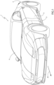
Figure 1 is a schematic perspective view, with parts removed for clarity, of a vehicle provided with a preferred embodiment of the coupling unit of the present invention; -
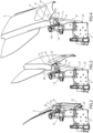
Figures 2 to 4 are three schematic perspective views, with parts removed for clarity, of a detail of the vehicle ofFigure 1 shown in three different operating positions; -
Figures 5 to 7 are three schematic perspective views, with parts removed for clarity, of a detail ofFigures 2 to 4 shown in three different operating positions; -
Figure 8 is a schematic perspective view of a detail ofFigures 5 to 7 ; and -
Figure 9 schematically shows the operating principle of the detail ofFigure 8 . - With reference to
Figures 1 to 9 , reference numeral 1 indicates, as a whole, a vehicle comprising a supportingframe 2 defining at least part of a lower floor 3 of the vehicle 1; and apassenger compartment 4, which is mounted on theframe 2, projects upwards from the floor 3, and is provided, in this case, with twodoors 5. - Each
door 5 is connected to theframe 2 through a relative coupling unit 6 comprising afirst coupling device 7 configured to be fixed to theframe 2 through afastening plate 8 and asecond coupling device 9 configured to be fixed to thedoor 5 through afastening plate 10. - The
device 9 comprises twocoupling rods plate 8 throughrespective ball joints plate 8 and in part on thecoupling rods - The
device 9 further comprises threeshaped rods rod 15 projects from theplate 10, therod 16 projects from therod 15, and therod 17 projects from therod 16. - Each
rod relative coupling rod relative ball joint rod coupling rod - The
rod 17 is connected to theplate 8 through aball joint 20 obtained in part on theplate 8 and in part on therod 17. - The unit 6 further comprises a variable-
length tie rod 21, which extends between theframe 2 and thedoor 5, and is coupled to theframe 2 and to thedoor 5 through the interposition ofrespective ball joints 22. - The unit 6 allows the
door 5 to move between a closed position (Figure 2 ), an open position (Figure 4 ), and an intermediate position (Figure 3 ). - The
coupling rods longitudinal axes 23 which intersect one another in a rotation centre C1, the position of which in the space varies following the movement of thedoor 5 between its open position and its closed position. - Consequently, the
door 5 is movable around arotation axis 24, which extends through the centre C1 and through a rotation centre C2 of thejoint 20, and has a position in the space which varies following the movement of thedoor 5 between its open position and its closed position. - The vehicle 1 has some advantages mainly deriving from the fact that each coupling unit 6 is configured to move the
relative door 5 progressively along a substantially curvilinear trajectory comprising a first section, in which the movement of thedoor 5 between the closed position and the intermediate position has a component of horizontal motion, and a second section, in which the movement of thedoor 5 between the intermediate position and the open position has a component of vertical motion. - Consequently, the movement of the
door 5 from its closed position to its open position around therotation axis 24 involves a relatively reduced lateral bulk of the vehicle 1, measured transverse to atravel direction 25 of the vehicle 1, and allows the vehicle 1 to be parked in relatively narrow spaces.
Claims (9)
- A coupling unit for coupling a door (5) to a frame (2) of a vehicle, the coupling unit comprising a first coupling device (7) configured to be fixed to the frame (2) of the vehicle; and a second coupling device (9) configured to be fixed to the door (5) of the vehicle and movable, relative to the first coupling device (7), between an open position and a closed position of the door (5); and being characterized in that the second coupling device (9) is connected to the first coupling device (7) so as to rotate, relative to the frame (2), around a rotation axis (24), which is variable in the space during the opening and the closing of the door (5).
- The coupling unit according to claim 1 and further comprising a variable-length tie rod (21) configured to be connected to the door (5) and to the frame (2).
- The coupling unit according to claim 2, wherein the variable-length tie rod (21) is configured to be connected to the door (5) and to the frame (2) through respective first ball joints (22).
- The coupling unit according to any one of the preceding claims, wherein the second coupling device (9) comprises two coupling rods (11, 12), each configured to be connected to the first coupling device (7) through a relative second ball joint (13, 14).
- The coupling unit according to claim 4, wherein the second coupling device (9) further comprises two coupling elements (15, 16), each connected to a relative coupling rod (11, 12) through a relative third ball joint (18, 19).
- The coupling unit according to claim 5, wherein the second coupling device (9) further comprises a further coupling element (17) configured to be connected to the first coupling device (7) through a fourth ball joint (20).
- The coupling unit according to claim 6, wherein the coupling rods (11, 12) have respective longitudinal axes (23) intersecting one another in a rotation centre (C1), which is variable in the space; the rotation axis (24) extending through the rotation centre (C1) defined by the longitudinal axes (23) of the coupling rods (11, 12) and through a rotation centre (C2) of the fourth ball joint (20) .
- A vehicle comprising a frame (2); a door (5); and a coupling unit (6) for coupling the door (5) to the frame (2); the coupling unit (6) comprising a first coupling device (7) fixed to the frame (2) and a second coupling device (9) fixed to the door (5) and movable, relative to the frame (2), between an open position and a closed position of the door (5); and characterized in that the second coupling device (9) is connected to the first coupling device (7) so as to rotate, relative to the frame (2), around a rotation axis (24), which is variable in the space during the opening and the closing of the door (5).
- The vehicle according to claim 8, wherein the coupling unit (6) is further designed according to any one of the claims from 2 to 7.
Applications Claiming Priority (1)
| Application Number | Priority Date | Filing Date | Title |
|---|---|---|---|
| IT102023000021339A IT202300021339A1 (en) | 2023-10-13 | 2023-10-13 | COUPLING UNIT OF A DOOR TO A VEHICLE FRAME |
Publications (1)
| Publication Number | Publication Date |
|---|---|
| EP4538487A1 true EP4538487A1 (en) | 2025-04-16 |
Family
ID=89427062
Family Applications (1)
| Application Number | Title | Priority Date | Filing Date |
|---|---|---|---|
| EP24205771.9A Pending EP4538487A1 (en) | 2023-10-13 | 2024-10-10 | Coupling unit for coupling a door to a frame of a vehicle |
Country Status (2)
| Country | Link |
|---|---|
| EP (1) | EP4538487A1 (en) |
| IT (1) | IT202300021339A1 (en) |
Citations (2)
| Publication number | Priority date | Publication date | Assignee | Title |
|---|---|---|---|---|
| CN116838201A (en) * | 2022-03-25 | 2023-10-03 | 张家港长城汽车研发有限公司 | Scissor door hinge structure and vehicle |
| CN116838204A (en) * | 2023-07-20 | 2023-10-03 | 东风汽车集团股份有限公司 | Scissor door hinge and vehicle |
-
2023
- 2023-10-13 IT IT102023000021339A patent/IT202300021339A1/en unknown
-
2024
- 2024-10-10 EP EP24205771.9A patent/EP4538487A1/en active Pending
Patent Citations (2)
| Publication number | Priority date | Publication date | Assignee | Title |
|---|---|---|---|---|
| CN116838201A (en) * | 2022-03-25 | 2023-10-03 | 张家港长城汽车研发有限公司 | Scissor door hinge structure and vehicle |
| CN116838204A (en) * | 2023-07-20 | 2023-10-03 | 东风汽车集团股份有限公司 | Scissor door hinge and vehicle |
Also Published As
| Publication number | Publication date |
|---|---|
| IT202300021339A1 (en) | 2025-04-13 |
Similar Documents
| Publication | Publication Date | Title |
|---|---|---|
| DE102009034287B4 (en) | Drive arrangement for actuating a flap of a motor vehicle | |
| EP2591193B1 (en) | Guide rail for a window lift and door system for a vehicle door | |
| WO2016177742A1 (en) | Carrier device for a motor vehicle | |
| EP2755889A1 (en) | Lift flap device | |
| US10648210B1 (en) | Multi-linkage vehicle door hinge | |
| EP2845974A2 (en) | Cover flap assembly for a handle assembly of a motor vehicle door | |
| WO2010003841A1 (en) | Path-controlled window lifter of a motor vehicle | |
| DE102015211065A1 (en) | Two-part hinged door with secondary folding axis | |
| EP2511632B1 (en) | Refrigeration and/or freezer device | |
| DE69100488T2 (en) | Sliding door, especially for railroad cars. | |
| EP4538487A1 (en) | Coupling unit for coupling a door to a frame of a vehicle | |
| WO2019091969A1 (en) | Wing fitting for a piece of furniture, side wall of a body of a piece of furniture and piece of furniture comprising a side wall | |
| EP1771330B1 (en) | Aircraft door arrangement comprising a pivotable aircraft door | |
| DE102004003956B4 (en) | Tailgate of a motor vehicle | |
| EP4626767A1 (en) | Divisible door leaf segment | |
| US12110724B2 (en) | Actuator for vehicle flap | |
| JP4119958B2 (en) | Slide roof device for vehicle | |
| DE102011116174B4 (en) | Arrangement for fastening at least one rear door to a body of a vehicle and vehicle with such an arrangement | |
| DE202006006792U1 (en) | Protective cap for automobile hatchback support rod ball joint | |
| SK7298A3 (en) | Guiding, displacement and locking device for sliding sides of freight cars | |
| EP2607124B1 (en) | Open roof construction for a vehicle | |
| KR20250004661A (en) | Device for guiding the sliding door of a vehicle | |
| DE102013202801B4 (en) | Device for the motorized actuation of a motor vehicle door with locking function | |
| WO2018215392A1 (en) | Lift car for a lift installation and method for opening and closing a door opening | |
| EP3524763B1 (en) | Secondary retention device for bi-parting doors |
Legal Events
| Date | Code | Title | Description |
|---|---|---|---|
| PUAI | Public reference made under article 153(3) epc to a published international application that has entered the european phase |
Free format text: ORIGINAL CODE: 0009012 |
|
| STAA | Information on the status of an ep patent application or granted ep patent |
Free format text: STATUS: THE APPLICATION HAS BEEN PUBLISHED |
|
| AK | Designated contracting states |
Kind code of ref document: A1 Designated state(s): AL AT BE BG CH CY CZ DE DK EE ES FI FR GB GR HR HU IE IS IT LI LT LU LV MC ME MK MT NL NO PL PT RO RS SE SI SK SM TR |
|
| STAA | Information on the status of an ep patent application or granted ep patent |
Free format text: STATUS: REQUEST FOR EXAMINATION WAS MADE |
|
| 17P | Request for examination filed |
Effective date: 20250902 |
|
| STAA | Information on the status of an ep patent application or granted ep patent |
Free format text: STATUS: EXAMINATION IS IN PROGRESS |
|
| 17Q | First examination report despatched |
Effective date: 20251103 |