EP4538462A1 - Snow thrower - Google Patents
Snow thrower Download PDFInfo
- Publication number
- EP4538462A1 EP4538462A1 EP24198047.3A EP24198047A EP4538462A1 EP 4538462 A1 EP4538462 A1 EP 4538462A1 EP 24198047 A EP24198047 A EP 24198047A EP 4538462 A1 EP4538462 A1 EP 4538462A1
- Authority
- EP
- European Patent Office
- Prior art keywords
- snow
- electric motor
- thrower
- equal
- rotational speed
- Prior art date
- Legal status (The legal status is an assumption and is not a legal conclusion. Google has not performed a legal analysis and makes no representation as to the accuracy of the status listed.)
- Granted
Links
Images













Classifications
-
- E—FIXED CONSTRUCTIONS
- E01—CONSTRUCTION OF ROADS, RAILWAYS, OR BRIDGES
- E01H—STREET CLEANING; CLEANING OF PERMANENT WAYS; CLEANING BEACHES; DISPERSING OR PREVENTING FOG IN GENERAL CLEANING STREET OR RAILWAY FURNITURE OR TUNNEL WALLS
- E01H5/00—Removing snow or ice from roads or like surfaces; Grading or roughening snow or ice
- E01H5/04—Apparatus propelled by animal or engine power; Apparatus propelled by hand with driven dislodging or conveying levelling elements, conveying pneumatically for the dislodged material
- E01H5/08—Apparatus propelled by animal or engine power; Apparatus propelled by hand with driven dislodging or conveying levelling elements, conveying pneumatically for the dislodged material dislodging essentially by driven elements
- E01H5/09—Apparatus propelled by animal or engine power; Apparatus propelled by hand with driven dislodging or conveying levelling elements, conveying pneumatically for the dislodged material dislodging essentially by driven elements the elements being rotary or moving along a closed circular path, e.g. rotary cutter, digging wheels
- E01H5/098—Apparatus propelled by animal or engine power; Apparatus propelled by hand with driven dislodging or conveying levelling elements, conveying pneumatically for the dislodged material dislodging essentially by driven elements the elements being rotary or moving along a closed circular path, e.g. rotary cutter, digging wheels about horizontal or substantially horizontal axises perpendicular or substantially perpendicular to the direction of clearing
-
- E—FIXED CONSTRUCTIONS
- E01—CONSTRUCTION OF ROADS, RAILWAYS, OR BRIDGES
- E01H—STREET CLEANING; CLEANING OF PERMANENT WAYS; CLEANING BEACHES; DISPERSING OR PREVENTING FOG IN GENERAL CLEANING STREET OR RAILWAY FURNITURE OR TUNNEL WALLS
- E01H5/00—Removing snow or ice from roads or like surfaces; Grading or roughening snow or ice
- E01H5/04—Apparatus propelled by animal or engine power; Apparatus propelled by hand with driven dislodging or conveying levelling elements, conveying pneumatically for the dislodged material
- E01H5/08—Apparatus propelled by animal or engine power; Apparatus propelled by hand with driven dislodging or conveying levelling elements, conveying pneumatically for the dislodged material dislodging essentially by driven elements
- E01H5/09—Apparatus propelled by animal or engine power; Apparatus propelled by hand with driven dislodging or conveying levelling elements, conveying pneumatically for the dislodged material dislodging essentially by driven elements the elements being rotary or moving along a closed circular path, e.g. rotary cutter, digging wheels
- E01H5/096—Apparatus propelled by animal or engine power; Apparatus propelled by hand with driven dislodging or conveying levelling elements, conveying pneumatically for the dislodged material dislodging essentially by driven elements the elements being rotary or moving along a closed circular path, e.g. rotary cutter, digging wheels about axes parallel or substantially parallel to the direction of clearing
-
- E—FIXED CONSTRUCTIONS
- E01—CONSTRUCTION OF ROADS, RAILWAYS, OR BRIDGES
- E01H—STREET CLEANING; CLEANING OF PERMANENT WAYS; CLEANING BEACHES; DISPERSING OR PREVENTING FOG IN GENERAL CLEANING STREET OR RAILWAY FURNITURE OR TUNNEL WALLS
- E01H5/00—Removing snow or ice from roads or like surfaces; Grading or roughening snow or ice
- E01H5/04—Apparatus propelled by animal or engine power; Apparatus propelled by hand with driven dislodging or conveying levelling elements, conveying pneumatically for the dislodged material
- E01H5/045—Means per se for conveying or discharging the dislodged material, e.g. rotary impellers, discharge chutes
Definitions
- the present application relates to a garden tool and, in particular, to a snow thrower.
- a snow thrower in the related art typically includes a snow collection device and a snow throwing device.
- the snow collection device collects snow on the ground, and then the snow throwing device throws the snow to a specified position.
- rotational speeds of a snow collection device and a snow throwing device of each of some snow throwers are adjustable.
- a rotational speed of the snow collection device needs to be adjusted, a rotational speed of the snow throwing device also varies accordingly. In this manner, the snow thrower cannot control a snow throwing distance and is more likely to stall.
- An object of the present application is to solve or at least alleviate part or all of the preceding problems. Therefore, an object of the present application is to provide a snow thrower with lower costs and higher energy efficiency.
- a snow thrower includes: a snow collection device including a snow collection element for collecting snow and a first electric motor configured to drive the snow collection element to rotate; a snow throwing device including a snow throwing element for throwing out the snow collected by the snow collection device, a discharge chute guiding a snow throwing direction, and a second electric motor driving the snow throwing element to rotate; a main housing for supporting the snow collection device and the snow throwing device; a walking assembly driving the snow thrower to walk on the ground; and a power supply device configured to power the first electric motor and the second electric motor.
- a working current of the first electric motor is less than or equal to 40 A when the snow collection element works with no load.
- a working current of the second electric motor is less than or equal to 40 A when the snow collection element works with no load.
- a sum of the working current of the first electric motor and a working current of the second electric motor is less than or equal to 80 A when the snow collection element works with no load.
- the power supply device includes a battery pack configured to power the first electric motor and/or the second electric motor, and a nominal voltage of the battery pack is higher than or equal to 24 V.
- the nominal voltage of the battery pack is higher than or equal to 40 V.
- the snow thrower according further includes a control device configured to adjust a rotational speed of the first electric motor in response to a variation in a load.
- a rotational speed of the second electric motor remains constant.
- a rotational speed of the second electric motor is kept at a value of a rotational speed corresponding to a set snow throwing distance.
- the snow collection device further includes a first transmission assembly connected to the first electric motor and the snow collection element.
- the snow collection device further includes a second transmission assembly connected to the second electric motor and the snow throwing element.
- a snow thrower includes: a snow collection device including a snow collection element for collecting snow and a first electric motor configured to drive the snow collection element to rotate; a snow throwing device including a snow throwing element for throwing out the snow collected by the snow collection device, a discharge chute guiding a snow throwing direction, and a second electric motor driving the snow throwing element to rotate; a main housing for supporting the snow collection device and the snow throwing device; a walking assembly driving the snow thrower to walk on the ground; and a power supply device configured to power the first electric motor and the second electric motor.
- the snow collection device further includes a first transmission assembly disposed between the first electric motor and the snow collection element to transmit power between the first electric motor and the snow collection element.
- a rotational speed of the first electric motor is higher than or equal to 5000 rpm and lower than or equal to 20000 rpm, and a reduction ratio of the first transmission assembly is higher than or equal to 40 and lower than or equal to 200.
- a rotational speed of the second electric motor is higher than or equal to 5000 rpm and lower than or equal to 14000 rpm.
- the snow throwing device further includes a second transmission assembly disposed between the second electric motor and the snow throwing element to transmit power between the second electric motor and the snow throwing element, and a reduction ratio of the second transmission assembly is higher than or equal to 4 and lower than or equal to 20.
- the first transmission assembly includes a first gear rotating about a first axis, and a second gear meshing with the first gear and rotating about a second axis.
- first axis and the second axis are parallel to each other.
- the second axis is oblique or perpendicular to the first axis.
- a diameter of the first electric motor is greater than or equal to 30 mm and less than or equal to 110 mm.
- a diameter of the second electric motor is greater than or equal to 60 mm and less than or equal to 135 mm.
- the reduction ratio of the first transmission assembly is higher than or equal to 80 and lower than or equal to 120.
- a snow thrower includes: a snow collection device including a snow collection element for collecting snow and a first electric motor configured to drive the snow collection element to rotate; a snow throwing device including a snow throwing element for throwing out the snow collected by the snow collection device, a discharge chute guiding a snow throwing direction, and a second electric motor driving the snow throwing element to rotate; a main housing for supporting the snow collection device and the snow throwing device; a walking assembly driving the snow thrower to walk on the ground; and a power supply device configured to power the first electric motor and the second electric motor.
- the snow collection device further includes a first transmission assembly disposed between the first electric motor and the snow collection element to transmit power between the first electric motor and the snow collection element. A reduction ratio of the first transmission assembly is higher than or equal to 60 and lower than or equal to 180.
- a snow thrower includes: a snow collection device including a snow collection element for collecting snow and a first electric motor configured to drive the snow collection element to rotate; a snow throwing device including a snow throwing element for throwing out the snow collected by the snow collection device, a discharge chute guiding a snow throwing direction, and a second electric motor driving the snow throwing element to rotate; a main housing for supporting the snow collection device and the snow throwing device; and a walking assembly driving the snow thrower to walk on the ground.
- a ratio of no-load output power of the second electric motor to no-load output power of the first electric motor is higher than or equal to 0.5 and lower than or equal to 1.5
- the snow thrower further includes a power supply device configured to power the first electric motor and the second electric motor.
- the no-load output power of the first electric motor is greater than or equal to 600 W and less than or equal to 2000 W
- the no-load output power of the second electric motor is greater than or equal to 600 W and less than or equal to 2000 W
- a sum of the no-load output power of the first electric motor and the no-load output power of the second electric motor is greater than or equal to 1200 W and less than or equal to 4000 W
- maximum load power of the second electric motor is greater than or equal to 4000 W.
- the snow thrower further includes: a control device configured to adjust a ratio of load output power of the second electric motor to load output power of the first electric motor according to a load.
- a ratio of load output power of the second electric motor to load output power of the first electric motor is different from the ratio of the no-load output power of the second electric motor to the no-load output power of the first electric motor.
- a ratio of load output power of the second electric motor to load output power of the first electric motor is higher than the ratio of the no-load output power of the second electric motor to the no-load output power of the first electric motor.
- a diameter of the first electric motor is greater than or equal to 30 mm and less than or equal to 110 mm.
- a diameter of the second electric motor is greater than or equal to 60 mm and less than or equal to 135 mm.
- a snow thrower includes: a snow collection device including a snow collection element for collecting snow and a first electric motor configured to drive the snow collection element to rotate; a snow throwing device including a snow throwing element for throwing out the snow collected by the snow collection device and a second electric motor driving the snow throwing element to rotate; a main housing for supporting the snow collection device and the snow throwing device; a walking assembly driving the snow thrower to walk on the ground; and a power supply device configured to power the first electric motor and the second electric motor.
- the snow throwing device further includes: a discharge chute for guiding a snow throwing direction; and a snow throwing cap connected to the discharge chute to guide a snow throwing height.
- a distance between a position where the snow is guided by the snow throwing device to fall on the ground and a central axis of the discharge chute is defined as a snow throwing distance, and a maximum snow throwing distance that the snow thrower is capable of reaching is greater than or equal to 10 m and less than or equal to 21 m.
- the snow thrower further includes a control device configured to adjust a rotational speed of the first electric motor according to a load.
- a rotational speed of the second electric motor does not vary with a variation in the rotational speed of the first electric motor.
- a rotational speed of the second electric motor is kept at a value of a rotational speed corresponding to a set snow throwing distance.
- a maximum rotational speed of the snow throwing element is higher than or equal to 500 rpm and lower than or equal to 2000 rpm.
- a ratio of no-load output power of the second electric motor to no-load output power of the first electric motor is higher than or equal to 0.5 and lower than or equal to 1.5.
- a ratio of load output power of the second electric motor to load output power of the first electric motor is different from a ratio of no-load output power of the second electric motor to no-load output power of the first electric motor.
- a ratio of load output power of the second electric motor to load output power of the first electric motor is higher than a ratio of no-load output power of the second electric motor to no-load output power of the first electric motor.
- a snow thrower includes: a snow collection device including a snow collection element for collecting snow and a first electric motor configured to drive the snow collection element to rotate; a main housing for supporting the snow collection device; a walking assembly driving the snow thrower to walk on the ground; and a power supply device configured to power the first electric motor.
- the projection of the first electric motor on the plane where the coordinate system is located is within a circular region using the origin as a center of a circle and located in the plane where the coordinate system is located, and a radius of the circular region is less than or equal to 0.7 m.
- the first side of the angular region is within the first quadrant of the coordinate system and the included angle between the first side of the angular region and the positive direction of the Y-axis is less than or equal to 30 degrees
- the second side of the angular region is within the second quadrant of the coordinate system and the included angle between the second side of the angular region and the positive direction of the Y-axis is less than or equal to 60 degrees.
- the main housing includes a snow collection cover for mounting the snow collection element, wherein the snow collection cover includes a top wall and two sidewalls disposed on two sides of the top wall one to one, and a projection of the first electric motor on a plane perpendicular to the front and rear direction is between projections of the two sidewalls on the plane perpendicular to the front and rear direction.
- the main housing includes a snow collection cover for mounting the snow collection element, wherein the snow collection cover includes a top wall and two sidewalls disposed on two sides of the top wall one to one, and the first electric motor is at least partially disposed on an upper side of the top wall.
- the main housing further includes a first electric motor housing formed with a first accommodation space for accommodating the first electric motor, and the first electric motor housing is mounted on the upper side of the top wall.
- the snow thrower further includes a snow throwing device including a snow throwing element for throwing out the snow collected by the snow collection device, a discharge chute guiding a snow throwing direction, and a second electric motor driving the snow throwing element to rotate.
- the first electric motor is disposed on a front side of the second electric motor in the front and rear direction.
- a snow thrower includes a snow collection device including a snow collection element for collecting snow; a snow throwing device including a snow throwing element for throwing out the snow collected by the snow collection device; a main housing used for supporting the snow collection device and the snow throwing device and further including a snow collection cover for mounting the snow collection element; a walking assembly driving the snow thrower to walk on the ground; and a detection device including a first detection assembly configured to detect a state of snow on a left side of the snow collection cover and a second detection assembly configured to detect a state of snow on a right side of the snow collection cover.
- the first detection assembly further includes a first sensor detecting the displacement of the first detection element.
- the snow collection cover includes a top wall and a first sidewall and a second sidewall that are disposed on two sides of the top wall, respectively, and the first detection assembly is mounted to the first sidewall.
- the first detection assembly is at least partially disposed on an outer side of the first sidewall to detect a thickness of snow on the outer side of the first sidewall.
- the second detection assembly is disposed on the second sidewall.
- a snow thrower includes: a snow collection device including a snow collection element for collecting snow and a first electric motor configured to drive the snow collection element to rotate; a snow throwing device including a snow throwing element for throwing out the snow collected by the snow collection device, a discharge chute guiding a snow throwing direction, and a second electric motor driving the snow throwing element to rotate; a main housing for supporting the snow collection device and the snow throwing device; a walking assembly driving the snow thrower to walk on the ground; a power supply device configured to power the first electric motor and the second electric motor; and a control device configured to control a rotational speed of the first electric motor according to at least a state of the snow and a walking speed of the walking assembly.
- the state of the snow includes a thickness of the snow and/or a density of the snow, and when the walking speed of the walking assembly remains constant, a greater thickness of the snow and/or a higher density of the snow indicates a higher rotational speed of the first electric motor.
- the state of the snow includes a thickness of the snow and/or a density of the snow.
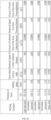
- the snow thrower further includes: a memory storing a mapping relationship among the state of the snow, the walking speed of the walking assembly, and the rotational speed of the first electric motor. After acquiring the state of the snow and the walking speed, the control device acquires the rotational speed of the first electric motor according to the mapping relationship.
- the mapping relationship includes a relationship table and/or a relationship function.
- a snow thrower includes: a snow collection device including a snow collection element for collecting snow and a first electric motor configured to drive the snow collection element to rotate; a snow throwing device including a snow throwing element for throwing out the snow collected by the snow collection device, a discharge chute guiding a snow throwing direction, and a second electric motor driving the snow throwing element to rotate; a main housing for supporting the snow collection device and the snow throwing device; a walking assembly driving the snow thrower to walk on the ground; a power supply device configured to power the first electric motor and the second electric motor; and a control device configured to control a rotational speed of the first electric motor according to at least a walking speed of the walking assembly.
- a rotational speed of the second electric motor does not vary with a variation in the rotational speed of the first electric motor.
- the snow thrower further includes a detection device configured to detect the state of the snow.
- control device is configured to adjust the rotational speed of the first electric motor according to the state of the snow and then control the walking speed of the walking assembly according to the state of the snow and the rotational speed of the first electric motor.
- a snow thrower includes: a snow collection device including a snow collection element for collecting snow and a first electric motor configured to drive the snow collection element to rotate; a snow throwing device including a snow throwing element for throwing out the snow collected by the snow collection device, a discharge chute guiding a snow throwing direction, and a second electric motor driving the snow throwing element to rotate; a main housing for supporting the snow collection device and the snow throwing device; a walking assembly driving the snow thrower to walk on the ground; a power supply device configured to power the first electric motor and the second electric motor; and a control device configured to control a walking speed of the walking assembly according to at least a state of the snow.
- a snow thrower includes: a snow collection device including a snow collection element for collecting snow and a first electric motor configured to drive the snow collection element to rotate; a snow throwing device including a snow throwing element for throwing out the snow collected by the snow collection device, a discharge chute guiding a snow throwing direction, and a second electric motor driving the snow throwing element to rotate; a main housing for supporting the snow collection device and the snow throwing device; a walking assembly driving the snow thrower to walk on the ground and further including a walking electric motor; a mode setting member configured to be operated by a user to set a working mode of the snow thrower; and a control device connected to the mode setting member.
- the mode setting member is at least capable of causing the snow thrower to enter a first working mode and a second working mode, wherein when the snow thrower is in the first working mode, the control device controls the walking electric motor to run at a first preset rotational speed and controls the first electric motor to run at a second preset rotational speed, and when the snow thrower is in the second working mode, the control device controls the walking electric motor to run at a third preset rotational speed and controls the first electric motor to run at a fourth preset rotational speed.
- the third preset rotational speed is different from the first preset rotational speed
- the fourth preset rotational speed is different from the second preset rotational speed.
- the third preset rotational speed is different from the first preset rotational speed
- the fourth preset rotational speed is different from the second preset rotational speed
- the mode setting member is further configured to be capable of causing the snow thrower to enter a third working mode, wherein when the snow thrower is in the third working mode, the control device controls the walking electric motor to run at a fifth preset rotational speed and controls the first electric motor to run at a sixth preset rotational speed.
- a rotational speed of the second electric motor does not vary with a variation in the rotational speed of the first electric motor.
- control device controls a rotational speed of the first electric motor to vary
- control device controls a rotational speed of the second electric motor to remain constant
- the main housing further includes a snow collection cover, and the first mark is provided on the snow collection cover at a first height from the ground.
- a second mark corresponding to the second working mode is further provided on a snow collection cover.
- a snow thrower includes: a snow removal device configured to clear snow on the ground; and a main housing for supporting the snow removal device.
- the snow thrower further includes: a power unit configured to drive the snow removal device to move and including at least one electric motor; a power supply device configured to power the at least one electric motor and including at least one battery pack; a first-stage snow removal assembly including a first snow removal blade and a first mounting shaft for mounting the first snow removal blade; a second-stage snow removal assembly including a second snow removal blade and a second mounting shaft for mounting the second snow removal blade; and a third-stage snow removal assembly including a third snow removal blade and a third mounting shaft for mounting the third snow removal blade.
- the main housing includes a battery compartment, the at least one battery pack is detachably disposed in the battery compartment, and a ratio of total energy of the at least one battery pack to a number of stages of snow removal assemblies in the snow removal device is higher than or equal to 45 Wh and lower than or equal to 1000 Wh.
- the at least one electric motor includes a first electric motor driving the first-stage snow removal assembly and a third electric motor driving the third-stage snow removal assembly.
- the second mounting shaft extends along a left and right direction, and a ratio of a rotational speed of the third snow removal blade to a rotational speed of the second snow removal blade is higher than or equal to 6 and lower than or equal to 18.
- a snow thrower includes: a snow removal device configured to clear snow on the ground; and a main housing for supporting the snow removal device.
- the snow thrower further includes: a power unit configured to drive the snow removal device to move and including at least one electric motor; and a power supply device configured to power the at least one electric motor and including at least one battery pack.
- the snow removal device includes: a first-stage snow removal assembly including a first snow removal blade and a first mounting shaft for mounting the first snow removal blade; a second-stage snow removal assembly including a second snow removal blade and a second mounting shaft for mounting the second snow removal blade; and a third-stage snow removal assembly including a third snow removal blade and a third mounting shaft for mounting the third snow removal blade.
- a snow thrower includes: a snow removal device configured to clear snow on the ground; and a main housing for supporting the snow removal device.
- the snow thrower further includes: a power unit configured to drive the snow removal device to move and including at least one electric motor; a power supply device configured to power the at least one electric motor and including at least one battery pack; and a discharge chute assembly mounted to the main housing and used for guiding a snow throwing direction.
- the at least one electric motor includes a first electric motor driving the first-stage snow removal assembly and/or the second-stage snow removal assembly and a third electric motor driving the third-stage snow removal assembly, wherein load output power of the third electric motor is greater than load output power of the first electric motor.
- the first mounting shaft extends along a left and right direction, and a ratio of a rotational speed of the third snow removal blade to a rotational speed of the first snow removal blade is higher than or equal to 6 and lower than or equal to 18.
- the power unit includes: a first electric motor configured to drive at least one of the first-stage snow removal assembly, the second-stage snow removal assembly, and the third-stage snow removal assembly; and a second electric motor configured to drive at least another one of the first-stage snow removal assembly, the second-stage snow removal assembly, and the third-stage snow removal assembly.
- the first mounting shaft extends along a left and right direction
- the snow thrower further includes a first reduction assembly connected to the first electric motor and the first mounting shaft.
- the third mounting shaft extends along a front and rear direction
- the snow thrower further includes a second reduction assembly connected to the second electric motor and the third mounting shaft.
- a reduction ratio of the second reduction assembly is higher than or equal to 4 and lower than or equal to 20.
- the first electric motor drives the first-stage snow removal assembly and the second-stage snow removal assembly
- the second electric motor drives the third-stage snow removal assembly
- the first electric motor drives the first-stage snow removal assembly
- the second electric motor drives the second-stage snow removal assembly
- the snow thrower further includes a third electric motor driving the third-stage snow removal assembly.
- the present application has the following benefits: the snow thrower has higher work efficiency, a lower energy loss, and the lower costs.
- controller In this application, the terms “controller”, “processor”, “central processor”, “CPU” and “MCU” are interchangeable. Where a unit “controller”, “processor”, “central processing”, “CPU”, or “MCU” is used to perform a specific function, the specific function may be implemented by a single aforementioned unit or a plurality of the aforementioned unit.
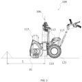
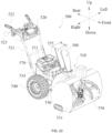
- a snow thrower 100 in an example is used by a user to clear snow on the ground, for example, snow on a road, snow in a courtyard, or snow in a garden.
- a walk-behind snow thrower 100 is used as an example of the snow thrower 100.
- the snow thrower 100 may be a smart snow thrower 100. The smart snow thrower 100 can move on the ground by itself without being followed by the user to clear the snow on the ground.
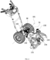
- the walking assembly 12 includes walking wheels 121 for driving the snow thrower 100 to walk on the ground and further includes a walking electric motor 122 configured to drive the walking wheels 121 to rotate.
- the walking electric motor 122 drives the walking wheels 121 to rotate about a walking axis 101.
- the walking wheels 121 include a left walking wheel and a right walking wheel.
- the left walking wheel and the right walking wheel support the main housing 11 and are disposed on two sides of the main housing 11, respectively.
- the power supply device 15 may power the walking electric motor 122. In a left and right direction, the power supply device 15 is disposed between the left walking wheel and the right walking wheel.
- the power supply device 15 is at least partially disposed on the upper side of the left walking wheel and the right walking wheel.
- the walking electric motor 122 is disposed under the power supply device 15 and connected to the left walking wheel and the right walking wheel through a reduction assembly.
- one walking electric motor 122 is provided.
- the reduction assembly may include a clutch so that a speed difference may exist between the left walking wheel and the right walking wheel, thereby steering the snow thrower 100.
- the walking assembly 12 may include two walking electric motors 122 driving the left walking wheel and the right walking wheel respectively so that a speed difference may exist between the left walking wheel and the right walking wheel, thereby steering the snow thrower 100.
- the walking electric motor 122 is an outrunner.
- the snow collection element 131 rotates about the first rotation axis 102
- the snow on the ground is stirred by the augers so that the snow on the ground enters the snow collection cover 111 through the opening 112.
- the two augers can also gather the snow to the middle of the opening 112 to improve snow collection efficiency.
- the snow is stirred by the impeller to rotate along the circumferential direction to the position of the discharge chute 143 and move along the discharge chute 143 to the outside of the snow thrower 100, so as to be thrown to the preset position.
- a rotational speed of the snow throwing element 141 also varies. For example, when the rotational speed of the snow collection element 131 increases, the rotational speed of the snow throwing element 141 also increases, and when the rotational speed of the snow collection element 131 decreases, the rotational speed of the snow throwing element 141 also decreases. Therefore, the matching relationship between the rotational speed of the snow throwing element 141 and the rotational speed of the snow collection element 131 cannot reach the most effective state. In other words, a relatively high energy loss is caused, or when the rotational speed of the snow collection element 131 decreases, the rotational speed of the snow throwing element 141 also decreases, which reduces a snow throwing distance.
- the first electric motor 132 driving the snow collection element 131 can be independently controlled to reduce the rotational speed while the rotational speed of the second electric motor 142 driving the snow throwing element 141 is kept constant, thereby reducing the energy loss of the snow thrower 100 without affecting the snow throwing distance.
- the working current of the first electric motor 132 when the snow collection element 131 works with no load, the working current of the first electric motor 132 is relatively small. In fact, when the snow collection element 131 works with a load, the working current of the first electric motor 132 is also reduced. In this manner, the work efficiency of the snow thrower 100 with the load can be improved, the battery lifetime of the snow thrower 100 is prolonged, the energy loss of the snow thrower 100 in a working process is reduced, and the utilization rate of electrical energy can be improved.
- the working current of the first electric motor 132 is further less than or equal to 30 A.
- the energy utilization rate of the electric snow thrower 100 can be further improved.
- the working current of the first electric motor 132 is further less than or equal to 20 A. In some examples, the working current of the first electric motor 132 is further less than or equal to 15 A.
- the first electric motor 132 can output a relatively high rotational speed, thereby improving the work efficiency of the snow thrower 100.
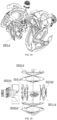
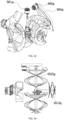
- the first transmission assembly 134 is used for implementing a speed reduction function between the first electric motor 132 and the snow collection element 131.
- the reduction ratio of the first transmission assembly 134 is higher than or equal to 40 and lower than or equal to 200.
- the snow collection element 131 can have higher output torque and drive thicker and heavier snow, thereby improving the load capacity of the snow thrower 100.
- the rotational speed of the first electric motor 132 is higher than or equal to 5000 rpm and lower than or equal to 20000 rpm so that the first electric motor 132 is lighter, smaller, and less costly.
- the rotational speed of the first electric motor 132 is higher than or equal to 10000 rpm and lower than or equal to 14000 rpm, and the reduction ratio of the first transmission assembly 134 is higher than or equal to 80 and lower than or equal to 120. In this manner, the rotational speed of the first electric motor 132, the reduction ratio of the first transmission assembly 134, and the relationship between the rotational speed of the first electric motor 132 and the reduction ratio of the first transmission assembly 134 can be optimized so that the snow collection device 13 works with relatively high efficiency.
- the gear set may further include a third gear 134c meshing with the second gear 134b.
- the third gear 134c rotates about a third axis 105.
- the third axis 105 and the second axis 104 are parallel to each other. It is to be understood that in another example, the first axis 103 and the second axis 104 may be parallel to each other.
- the second transmission assembly 144 may be a gear transmission assembly.
- the gear transmission assembly includes a gear set with gears mutually meshing with each other.
- the gear transmission assembly may be a planetary gear assembly, a worm gear assembly, or a bevel gear assembly.
- the second transmission assembly 144 may include multiple gears that mutually mesh with each other. The rotation axes of part of the multiple gears may be parallel to each other.
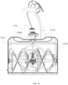
- a projection of the front edge of the first sidewall 111b on a plane perpendicular to the front and rear direction extends basically along the up and down direction
- a projection of the front edge of the second sidewall 111c on the plane perpendicular to the front and rear direction extends basically along the up and down direction.
- the rear wall 111d is connected to the top wall, the first sidewall 111b, and the second sidewall 111c.
- the rear wall 111d is at least partially arc-shaped.
- the rear wall 111d is formed with a snow inlet.
- the snow inlet is basically provided in the middle of the rear wall 111d in the left and right direction. In this manner, the snow collection element 131 can gather the snow towards the middle and guide the snow rearwards so that most of the snow can move towards the snow inlet, thereby improving the snow clearing efficiency.
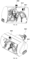
- a first side S1 of the angular region A is within the first quadrant of the coordinate system, and the included angle A1 between the first side S1 of the angular region A and the positive direction of the Y-axis is less than or equal to 60 degrees.
- a second side S2 of the angular region A is within the second quadrant of the coordinate system, and the included angle A2 between the second side S2 of the angular region A and the positive direction of the Y-axis is less than or equal to 80 degrees.
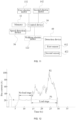
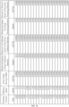
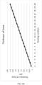
- FIG. 13A shows that the snow collection element 131 has different rotational speeds corresponding to different walking speeds when the thickness of the snow is 0.1 m.
- the rotational speed of the snow collection element 131 varies, the rotational speed of the snow throwing element 141 remains constant.
- a snow intake during a walk corresponding to the walking speed may be made to be less than the amount of collected snow of the snow collection element 131, and the amount of collected snow of the snow collection element 131 may be made to be less than the amount of thrown snow of the snow throwing element 141.
- the snow collection element 131 is required to be matched with a greater amount of collected snow to clear the snow completely.
- the greater the thickness of the snow and/or the higher the density of the snow the higher the rotational speed of the first electric motor 132. That is to say, when the walking speed of the walking assembly 12 remains constant, the snow intake during the walk of the walking assembly 12 increases if the snow becomes thicker. In this case, the snow collection element 131 is also required to be matched with a greater amount of collected snow to clear the snow completely.
- control device 30 may adjust the rotational speed of the second electric motor 142 according to the variation in the load and/or the variation in the walking speed and/or the variation in the rotational speed of the first electric motor 132 to control the snow thrower 100 more smartly.
- the control device 30 is connected to the memory 32. In this manner, after acquiring the state of the snow and the walking speed, the control device 30 may acquire the rotational speed of the first electric motor 132 according to the mapping relationship and then control the first electric motor 132 according to the obtained value.
- the snow thrower 100 clears the snow more smartly and efficiently, thereby improving the work efficiency and reducing the energy loss.
- the snow thrower 100 further includes a detection device 40 configured to detect the state of the snow.
- the control device 30 is communicatively or electrically connected to the detection device 40.
- the control device 30 acquires a state parameter of the snow through the detection device 40 to adjust the rotational speed of the first electric motor 132.
- the snow thrower 100 further includes a speed detection device 50.
- the speed detection device 50 may be electrically or communicatively connected to the control device 30.
- the speed detection device 50 is configured to detect the walking speed.
- the control device 30 acquires the walking speed through the speed detection device 50 to control the rotational speed of the first electric motor 132.
- the mapping relationship among the state of the snow, the walking speed of the walking assembly 12, and the rotational speed of the first electric motor 132 may be stored in the memory 32.
- the control device 30 may acquire, according to the mapping relationship, a walking speed and a rotational speed of the first electric motor 132 that are matched with the state parameter of the snow. Then, the control device 30 controls the walking electric motor 122 and the first electric motor 132. In this manner, the snow thrower 100 is controlled in a simpler manner. The snow thrower 100 only needs to identify the state parameter of the snow and automatically match the walking speed with the rotational speed of the first electric motor 132 so that the snow thrower 100 is controlled more smartly.
- the rotational speed of the first electric motor 132 is required to gradually increase so that covered snow can be collected as much as possible.
- the rotational speed of the first electric motor 132 needs to increase in this case. Hence, in this manner, the total power of the first electric motor 132, the walking electric motor 122, and the second electric motor 142 is caused to exceed the power outputted by the power supply device 15.
- the rotational speed of the second electric motor 142 may not vary with the variation in the rotational speed of the first electric motor 132 so that the rotational speed of the second electric motor 142 remains constant.
- the rotational speed of the first electric motor 132 is kept at a first constant rotational speed value.
- the first electric motor 132 works near the maximum efficiency point as far as possible.
- the walking speed of the walking assembly 12 gradually decreases as the state parameter of the snow increases.
- the snow thrower 100 is less likely to stall.
- the snow intake during the walk of the walking assembly 12 is less than or equal to the amount of collected snow of the snow collection element 131.
- the rotational speed of the first electric motor 132 is lower than the first constant rotational speed value, and the rotational speed of the first electric motor 132 further increases with the increase in the state parameter of the snow.
- the walking speed of the walking assembly 12 is kept at a second constant rotational speed value.
- the snow thrower 100 can clear the snow at a relatively high speed, thereby improving the work efficiency.
- the state parameter of the snow is greater than the first preset value, the walking speed is further less than a second constant rotational speed.
- the snow thrower 100 is started.
- the start of the snow thrower 100 may refer to that the snow thrower 100 is powered on and the walking electric motor 122 is started to cause the snow thrower 100 to walk on the ground.
- the start of the snow thrower 100 may refer to that the first electric motor 132 and/or the second electric motor 142 of the snow thrower 100 are also started.
- the walking electric motor 122 and the first electric motor 132 are controlled according to the acquired walking speed and the acquired rotational speed of the first electric motor 132.
- the duty cycle of the walking electric motor 122 and the duty cycle of the first electric motor 132 are controlled according to the acquired walking speed and the acquired rotational speed of the first electric motor 132 so that an output rotational speed of the walking electric motor 122 and the output rotational speed of the first electric motor 132 are controlled.
- the detection device 40 includes a first detection assembly 41 and a second detection assembly 42.
- the first detection assembly 41 is configured to detect snow on the left side of the snow collection cover 111
- the second detection assembly 42 is configured to detect snow on the right side of the snow collection cover 111.
- the state parameter of the snow may be detected through the first detection assembly 41
- the snow thrower 100 clears the snow on the right side
- the state parameter of the snow may be detected through the second detection assembly 42.
- the snow thrower 100 can be suitable for more working conditions and meet different usage habits of the user.
- the first detection assembly 41 and the second detection assembly 42 can make detection results more accurate.
- the first detection assembly 41 may be mounted on the first sidewall 111b of the snow collection cover 111 so that the first detection assembly 41 is located on the outer side of the main housing 11, and the second detection assembly 42 may be mounted on the second sidewall 111c so that the second detection assembly 42 is located on the outer side of the main housing 11.
- the detection device 40 is mounted to the side surfaces of the snow collection cover 111 so that the snow collected in the process where the snow thrower 100 clears the snow can be prevented from affecting the accuracy of the detection results.
- the user may set the working mode of the snow thrower 300 according to a work requirement.
- Walking speeds and rotational speeds of the snow collection element that correspond to different working modes may be stored in the memory 305.
- the control device 304 may calculate, according to the corresponding walking speeds and the corresponding rotational speeds of the snow collection element, rotational speeds of the walking electric motor 302 and rotational speeds of the first electric motor 303 that correspond to the different working modes.
- the mode setting member 301 may be further configured to cause the snow thrower 300 to enter a fourth working mode and a fifth working mode.
- the fourth working mode may correspond to a working condition at an intermediate load level 3
- the fifth working mode may correspond to the heavy load working condition.
- the number of working modes is not limited thereto.
- the first mark line may be provided on the snow collection cover 307 at a height of 0.05 m from the ground
- the second mark line may be provided on the snow collection cover 307 at a height of 0.1 m from the ground
- the third mark line may be provided on the snow collection cover 307 at a height of 0.2 m from the ground
- the fourth mark line may be provided on the snow collection cover 307 at a height of 0.3 m from the ground
- the fifth mark line may be provided on the snow collection cover 307 at a height of 0.4 m from the ground.
- up, down, front, rear, left, and right are defined, as shown by arrows in FIG. 23 .
- directions in this example are not limited thereto.
- the handle device 520 is connected to the rear end of the main housing 530.
- the handle device 520 includes connecting rods 521, an operation assembly 522, and gripping handles 523.
- the connecting rods 521 connect the operation assembly 522 to the body 510.
- the gripping handles 523 are disposed at the ends of the connecting rods 521 far away from the body 510.
- the gripping handles 523 include a left handle and a right handle. The left handle and the right handle are gripped by the two hands of the user, respectively.
- the operation assembly 522 includes an operation bench and multiple operation members.
- the walking electric motor 542 may be a hub motor.
- the hub motor is at least partially disposed in one of the walking wheels 541 to drive the walking wheels 541 to rotate.
- the walking electric motor 542 may be a wheel-side motor.
- the wheel-side motor is configured to be adjacent to one of the walking wheels 541 to drive the walking wheels 541 to rotate.
- the nominal voltage of the battery pack 571 is higher than or equal to 24 V. In some examples, the nominal voltage of the battery pack 571 is higher than or equal to 40 V. In some examples, the nominal voltage of the battery pack 571 is higher than or equal to 48 V. In some examples, the nominal voltage of the battery pack 571 may be, for example, 24 V, 36 V, 40 V, 56 V, or 80 V.
- the second-stage snow removal assembly 552 includes a second snow removal blade 5521 and a second mounting shaft 5522 for mounting the second snow removal blade 5521.
- the third-stage snow removal assembly 553 includes a third snow removal blade 5531 and a third mounting shaft 5532 for mounting the third snow removal blade 5531.
- the ratio of a rotational speed of the third snow removal blade 5531 to a rotational speed of the first snow removal blade 5511 is higher than or equal to 6 and lower than or equal to 18.
- the first mounting shaft 5512 of the first-stage snow removal assembly 551 extends along the left and right direction, and the first snow removal blade 5511 is rotatable about a first axis 501 along with the first mounting shaft 5512.
- the first snow removal blade 5511 can rapidly rotate to collect the snow on the ground so that the snow enters the snow collection cover 531 from the opening 533. In this manner, the first-stage snow removal assembly 551 may be considered to belong to the snow collection device.
- the power unit 560 includes at least one electric motor, and the power supply device 570 is configured to power the electric motor.
- the at least one electric motor includes two electric motors. One of the two electric motors drives at least one stage of a snow removal member in the snow removal device 550, and the other one of the two electric motors drives at least another stage of a snow removal assembly in the snow removal device 550.
- the power supply device 570 is configured to power the two electric motors.
- the at least one electric motor includes a first electric motor 561 and a third electric motor 562.
- the first electric motor 561 is configured to drive the first-stage snow removal assembly 551
- the third electric motor 562 is configured to drive the third-stage snow removal assembly 553.
- the third electric motor 562 further drives the second-stage snow removal assembly 552.
- load output power of the electric motor driving the third-stage snow removal assembly 553 is greater than load output power of the electric motor driving the first-stage snow removal assembly 551.
- load output power of the third electric motor 562 is greater than load output power of the first electric motor 561.
- the snow thrower 500 includes the first electric motor 561, the second electric motor, and the third electric motor 562
- the load output power of the third electric motor 562 is greater than the load output power of the first electric motor 561 and is further greater than load output power of the second electric motor.
- the first start switch 593 controls the start or stop of the first electric motor 561
- the second start switch 594 controls the start or stop of the second electric motor and the start or stop of the third electric motor 562.
- the start or stop of the first electric motor 561, the start or stop of the second electric motor, and the start or stop of the third electric motor 562 may be controlled by one start switch.
- FIG. 32 is a perspective view showing part of devices of a snow thrower in another example. As shown in FIGS. 32 and 33 , this example has basically the same structures as the snow thrower in the example shown in FIG. 30 . All solutions of the snow thrower shown in FIGS. 30 and 31 that can be suitable for the snow thrower in this example are applicable in this example. The following mainly introduces the different parts between this example and the example in FIG. 30 , and the identical parts thereof are not repeatedly described.
- first mounting shaft 5512d is located on the front side of a second mounting shaft 5522d to be used for mounting one of the two first snow removal blades 5511d.
- the other part of the first mounting shaft 5512d is located on the rear side of the second mounting shaft 5522d to be used for mounting the other one of the two first snow removal blades 5511d.
- the first snow removal blade 5511d located on the front side of the second mounting shaft 5522d is used for scraping the snow on the ground, that is, collecting the snow.
- the first snow removal blade 5511d located on the rear side of the second mounting shaft 5522d is used for transmitting the snow stirred by the second snow removal blade 5521d to a third snow removal blade 5531d, that is, throwing the snow.
- the first electric motor 561f is disposed on the inner side of a snow collection cover 531f and drives, through a first reduction assembly 563f, the first mounting shaft 5512f to rotate.
- the first reduction assembly 563f is disposed on the outer side of the snow collection cover 531f.
- the first reduction assembly 563f may be disposed on the outer surface of the left sidewall or right sidewall of the snow collection cover 531f.
- the first reduction assembly 563f may be a belt transmission assembly.
- a second mounting shaft 5522f extends along the front and rear direction.
- a second snow removal blade 5521f is disposed on the rear side of a first snow removal blade 5511f.
- the second electric motor 565f drives, through the second reduction assembly, the second mounting shaft 5522f to rotate and is disposed on the upper side of the top wall of the snow collection cover 531f.
- a third mounting shaft 5532f extends along the front and rear direction.
- the third electric motor 562f is disposed on the rear side of the third-stage snow removal assembly 553f to drive the third mounting shaft 5532f to rotate.
- the third electric motor 562f may drive, through a third reduction assembly, the third mounting shaft 5532f to rotate. In another example, the third electric motor 562f may directly drive the third mounting shaft 5532f to rotate.
Landscapes
- Engineering & Computer Science (AREA)
- Architecture (AREA)
- Civil Engineering (AREA)
- Structural Engineering (AREA)
- Cleaning Of Streets, Tracks, Or Beaches (AREA)
- Electric Propulsion And Braking For Vehicles (AREA)
- Suspension Of Electric Lines Or Cables (AREA)
Abstract
Description
- The present application relates to a garden tool and, in particular, to a snow thrower.
- A snow thrower in the related art typically includes a snow collection device and a snow throwing device. In the process where the snow thrower works, the snow collection device collects snow on the ground, and then the snow throwing device throws the snow to a specified position. Typically, it is inconvenient to adjust rotational speeds of the snow collection device and the snow throwing device of the snow thrower, which tends to cause a waste of energy and reduce the work efficiency. Nevertheless, rotational speeds of a snow collection device and a snow throwing device of each of some snow throwers are adjustable. However, when a rotational speed of the snow collection device needs to be adjusted, a rotational speed of the snow throwing device also varies accordingly. In this manner, the snow thrower cannot control a snow throwing distance and is more likely to stall.
- This part provides background information related to the present application, and the background information is not necessarily the existing art.
- An object of the present application is to solve or at least alleviate part or all of the preceding problems. Therefore, an object of the present application is to provide a snow thrower with lower costs and higher energy efficiency.
- To achieve the preceding object, the present application adopts the technical solutions below.
- In an example, a snow thrower includes: a snow collection device including a snow collection element for collecting snow and a first electric motor configured to drive the snow collection element to rotate; a snow throwing device including a snow throwing element for throwing out the snow collected by the snow collection device, a discharge chute guiding a snow throwing direction, and a second electric motor driving the snow throwing element to rotate; a main housing for supporting the snow collection device and the snow throwing device; a walking assembly driving the snow thrower to walk on the ground; and a power supply device configured to power the first electric motor and the second electric motor. A working current of the first electric motor is less than or equal to 40 A when the snow collection element works with no load.
- In an example, a working current of the second electric motor is less than or equal to 40 A when the snow collection element works with no load.
- In an example, a sum of the working current of the first electric motor and a working current of the second electric motor is less than or equal to 80 A when the snow collection element works with no load.
- In an example, the power supply device includes a battery pack configured to power the first electric motor and/or the second electric motor, and a nominal voltage of the battery pack is higher than or equal to 24 V.
- In an example, the nominal voltage of the battery pack is higher than or equal to 40 V.
- In an example, the snow thrower according further includes a control device configured to adjust a rotational speed of the first electric motor in response to a variation in a load.
- In an example, when the control device adjusts the rotational speed of the first electric motor in response to the variation in the load, a rotational speed of the second electric motor remains constant.
- In an example, when the control device adjusts the rotational speed of the first electric motor in response to the variation in the load, a rotational speed of the second electric motor is kept at a value of a rotational speed corresponding to a set snow throwing distance.
- In an example, the snow collection device further includes a first transmission assembly connected to the first electric motor and the snow collection element.
- In an example, the snow collection device further includes a second transmission assembly connected to the second electric motor and the snow throwing element.
- In an example, a snow thrower includes: a snow collection device including a snow collection element for collecting snow and a first electric motor configured to drive the snow collection element to rotate; a snow throwing device including a snow throwing element for throwing out the snow collected by the snow collection device, a discharge chute guiding a snow throwing direction, and a second electric motor driving the snow throwing element to rotate; a main housing for supporting the snow collection device and the snow throwing device; a walking assembly driving the snow thrower to walk on the ground; and a power supply device configured to power the first electric motor and the second electric motor. The snow collection device further includes a first transmission assembly disposed between the first electric motor and the snow collection element to transmit power between the first electric motor and the snow collection element. A rotational speed of the first electric motor is higher than or equal to 5000 rpm and lower than or equal to 20000 rpm, and a reduction ratio of the first transmission assembly is higher than or equal to 40 and lower than or equal to 200.
- In an example, a rotational speed of the second electric motor is higher than or equal to 5000 rpm and lower than or equal to 14000 rpm.
- In an example, the snow throwing device further includes a second transmission assembly disposed between the second electric motor and the snow throwing element to transmit power between the second electric motor and the snow throwing element, and a reduction ratio of the second transmission assembly is higher than or equal to 4 and lower than or equal to 20.
- In an example, the first transmission assembly includes a first gear rotating about a first axis, and a second gear meshing with the first gear and rotating about a second axis.
- In an example, the first axis and the second axis are parallel to each other.
- In an example, the second axis is oblique or perpendicular to the first axis.
- In an example, a diameter of the first electric motor is greater than or equal to 30 mm and less than or equal to 110 mm.
- In an example, a diameter of the second electric motor is greater than or equal to 60 mm and less than or equal to 135 mm.
- In an example, the reduction ratio of the first transmission assembly is higher than or equal to 80 and lower than or equal to 120.
- In an example, a snow thrower includes: a snow collection device including a snow collection element for collecting snow and a first electric motor configured to drive the snow collection element to rotate; a snow throwing device including a snow throwing element for throwing out the snow collected by the snow collection device, a discharge chute guiding a snow throwing direction, and a second electric motor driving the snow throwing element to rotate; a main housing for supporting the snow collection device and the snow throwing device; a walking assembly driving the snow thrower to walk on the ground; and a power supply device configured to power the first electric motor and the second electric motor. The snow collection device further includes a first transmission assembly disposed between the first electric motor and the snow collection element to transmit power between the first electric motor and the snow collection element. A reduction ratio of the first transmission assembly is higher than or equal to 60 and lower than or equal to 180.
- In an example, a snow thrower includes: a snow collection device including a snow collection element for collecting snow and a first electric motor configured to drive the snow collection element to rotate; a snow throwing device including a snow throwing element for throwing out the snow collected by the snow collection device, a discharge chute guiding a snow throwing direction, and a second electric motor driving the snow throwing element to rotate; a main housing for supporting the snow collection device and the snow throwing device; and a walking assembly driving the snow thrower to walk on the ground. When the snow collection element works with no load, a ratio of no-load output power of the second electric motor to no-load output power of the first electric motor is higher than or equal to 0.5 and lower than or equal to 1.5, and the snow thrower further includes a power supply device configured to power the first electric motor and the second electric motor.
- In an example, the no-load output power of the first electric motor is greater than or equal to 600 W and less than or equal to 2000 W
- In an example, the no-load output power of the second electric motor is greater than or equal to 600 W and less than or equal to 2000 W
- In an example, a sum of the no-load output power of the first electric motor and the no-load output power of the second electric motor is greater than or equal to 1200 W and less than or equal to 4000 W
- In an example, maximum load power of the second electric motor is greater than or equal to 4000 W.
- In an example, the snow thrower further includes: a control device configured to adjust a ratio of load output power of the second electric motor to load output power of the first electric motor according to a load.
- In an example, a ratio of load output power of the second electric motor to load output power of the first electric motor is different from the ratio of the no-load output power of the second electric motor to the no-load output power of the first electric motor.
- In an example, a ratio of load output power of the second electric motor to load output power of the first electric motor is higher than the ratio of the no-load output power of the second electric motor to the no-load output power of the first electric motor.
- In an example, a diameter of the first electric motor is greater than or equal to 30 mm and less than or equal to 110 mm.
- In an example, a diameter of the second electric motor is greater than or equal to 60 mm and less than or equal to 135 mm.
- In an example, a snow thrower includes: a snow collection device including a snow collection element for collecting snow and a first electric motor configured to drive the snow collection element to rotate; a snow throwing device including a snow throwing element for throwing out the snow collected by the snow collection device and a second electric motor driving the snow throwing element to rotate; a main housing for supporting the snow collection device and the snow throwing device; a walking assembly driving the snow thrower to walk on the ground; and a power supply device configured to power the first electric motor and the second electric motor. The snow throwing device further includes: a discharge chute for guiding a snow throwing direction; and a snow throwing cap connected to the discharge chute to guide a snow throwing height. A distance between a position where the snow is guided by the snow throwing device to fall on the ground and a central axis of the discharge chute is defined as a snow throwing distance, and a maximum snow throwing distance that the snow thrower is capable of reaching is greater than or equal to 10 m and less than or equal to 21 m.
- In an example, the snow thrower further includes a control device configured to adjust a rotational speed of the first electric motor according to a load.
- In an example, when the control device adjusts the rotational speed of the first electric motor according to a variation in the load, a rotational speed of the second electric motor does not vary with a variation in the rotational speed of the first electric motor.
- In an example, when the control device adjusts the rotational speed of the first electric motor according to a variation in the load, a rotational speed of the second electric motor is kept at a value of a rotational speed corresponding to a set snow throwing distance.
- In an example, the snow thrower further includes: an operation member operated by a user to adjust a rotational speed of the second electric motor to adjust the snow throwing distance.
- In an example, the snow throwing device further includes a transmission assembly disposed between the second electric motor and the snow throwing element to transmit power between the second electric motor and the snow throwing element.
- In an example, a maximum rotational speed of the snow throwing element is higher than or equal to 500 rpm and lower than or equal to 2000 rpm.
- In an example, when the snow collection element works with no load, a ratio of no-load output power of the second electric motor to no-load output power of the first electric motor is higher than or equal to 0.5 and lower than or equal to 1.5.
- In an example, a ratio of load output power of the second electric motor to load output power of the first electric motor is different from a ratio of no-load output power of the second electric motor to no-load output power of the first electric motor.
- In an example, a ratio of load output power of the second electric motor to load output power of the first electric motor is higher than a ratio of no-load output power of the second electric motor to no-load output power of the first electric motor.
- In an example, a snow thrower includes: a snow collection device including a snow collection element for collecting snow and a first electric motor configured to drive the snow collection element to rotate; a main housing for supporting the snow collection device; a walking assembly driving the snow thrower to walk on the ground; and a power supply device configured to power the first electric motor. The snow collection element rotates about a rotation axis, a coordinate system using a point on the rotation axis of the snow collection element as an origin, a front and rear direction as an X-axis, and an up and down direction as a Y-axis is established, a forward direction is a positive direction of the X-axis, an upward direction is a positive direction of the Y-axis, a projection of the first electric motor on a plane where the coordinate system is located is within an angular region using the origin as a vertex and located in the plane where the coordinate system is located, a first side of the angular region is within a first quadrant of the coordinate system and an included angle between the first side of the angular region and the positive direction of the Y-axis is less than or equal to 60 degrees, and a second side of the angular region is within a second quadrant of the coordinate system and an included angle between the second side of the angular region and the positive direction of the Y-axis is less than or equal to 80 degrees.
- In an example, the projection of the first electric motor on the plane where the coordinate system is located is within a circular region using the origin as a center of a circle and located in the plane where the coordinate system is located, and a radius of the circular region is less than or equal to 0.7 m.
- In an example, the first side of the angular region is within the first quadrant of the coordinate system and the included angle between the first side of the angular region and the positive direction of the Y-axis is less than or equal to 30 degrees, and the second side of the angular region is within the second quadrant of the coordinate system and the included angle between the second side of the angular region and the positive direction of the Y-axis is less than or equal to 60 degrees.
- In an example, the first electric motor is disposed on an upper side of the snow collection element.
- In an example, the first electric motor is disposed above the rotation axis of the snow collection element.
- In an example, the main housing includes a snow collection cover for mounting the snow collection element, wherein the snow collection cover includes a top wall and two sidewalls disposed on two sides of the top wall one to one, and a projection of the first electric motor on a plane perpendicular to the front and rear direction is between projections of the two sidewalls on the plane perpendicular to the front and rear direction.
- In an example, the main housing includes a snow collection cover for mounting the snow collection element, wherein the snow collection cover includes a top wall and two sidewalls disposed on two sides of the top wall one to one, and the first electric motor is at least partially disposed on an upper side of the top wall.
- In an example, the main housing further includes a first electric motor housing formed with a first accommodation space for accommodating the first electric motor, and the first electric motor housing is mounted on the upper side of the top wall.
- In an example, the snow thrower further includes a snow throwing device including a snow throwing element for throwing out the snow collected by the snow collection device, a discharge chute guiding a snow throwing direction, and a second electric motor driving the snow throwing element to rotate. The first electric motor is disposed on a front side of the second electric motor in the front and rear direction.
- In an example, a snow thrower includes: a snow collection device including a snow collection element for collecting snow and a first electric motor configured to drive the snow collection element to rotate; a snow throwing device including a snow throwing element for throwing out the snow collected by the snow collection device, a discharge chute guiding a snow throwing direction, and a second electric motor driving the snow throwing element to rotate; a main housing for supporting the snow collection device and the snow throwing device; a walking assembly driving the snow thrower to walk on the ground; and a power supply device configured to power the first electric motor and the second electric motor. The main housing includes a snow collection cover for mounting the snow collection element, wherein the snow collection cover includes a top wall and two sidewalls disposed on two sides of the top wall one to one, and the first electric motor is at least partially disposed on an upper side of the top wall.
- In an example, a snow thrower includes a snow collection device including a snow collection element for collecting snow; a snow throwing device including a snow throwing element for throwing out the snow collected by the snow collection device; a main housing used for supporting the snow collection device and the snow throwing device and further including a snow collection cover for mounting the snow collection element; a walking assembly driving the snow thrower to walk on the ground; and a detection device including a first detection assembly configured to detect a state of snow on a left side of the snow collection cover and a second detection assembly configured to detect a state of snow on a right side of the snow collection cover.
- In an example, the first detection assembly includes a first detection element that is capable of being driven by snow in front of the snow thrower or snow on a left side of the snow thrower to be displaced.
- In an example, the first detection element is configured to be rotatable relative to the main housing, and a size of a rotation angle of the first detection element varies with a variation in a thickness of the snow.
- In an example, the first detection assembly further includes a first sensor detecting the displacement of the first detection element.
- In an example, the first detection assembly is at least partially disposed on an outer side of the main housing.
- In an example, the snow collection cover includes a top wall and a first sidewall and a second sidewall that are disposed on two sides of the top wall, respectively, and the first detection assembly is mounted to the first sidewall.
- In an example, the first detection assembly is at least partially disposed on an outer side of the first sidewall to detect a thickness of snow on the outer side of the first sidewall.
- In an example, the second detection assembly is disposed on the second sidewall.
- In an example, the detection device further includes a control device configured to adjust a movement state of the snow thrower according to a state of snow detected by the detection device, and the control device acquires a current state parameter of the snow according to a state parameter of the left-side snow detected by the first detection assembly and a state parameter of the right-side snow detected by the second detection assembly.
- In an example, a snow blower includes: a snow collection device including a snow collection element for collecting snow; a snow throwing device including a snow throwing element for throwing out the snow collected by the snow collection device; a main housing for supporting the snow collection device and the snow throwing device; a walking assembly driving the snow thrower to walk on the ground; a detection device including a first detection assembly configured to detect a state of snow and a second detection assembly configured to detect a state of snow; and a control device configured to acquire a current state parameter of the snow according to a state parameter of the snow detected by the first detection assembly and/or a state parameter of the snow detected by the second detection assembly and control a movement state of the snow thrower according to the current state parameter of the snow.
- In an example, a snow thrower includes: a snow collection device including a snow collection element for collecting snow and a first electric motor configured to drive the snow collection element to rotate; a snow throwing device including a snow throwing element for throwing out the snow collected by the snow collection device, a discharge chute guiding a snow throwing direction, and a second electric motor driving the snow throwing element to rotate; a main housing for supporting the snow collection device and the snow throwing device; a walking assembly driving the snow thrower to walk on the ground; a power supply device configured to power the first electric motor and the second electric motor; and a control device configured to control a rotational speed of the first electric motor according to at least a state of the snow and a walking speed of the walking assembly.
- In an example, when the state of the snow remains constant, a higher walking speed of the walking assembly indicates a higher rotational speed of the first electric motor.
- In an example, the state of the snow includes a thickness of the snow and/or a density of the snow, and when the walking speed of the walking assembly remains constant, a greater thickness of the snow and/or a higher density of the snow indicates a higher rotational speed of the first electric motor.
- In an example, the state of the snow includes a thickness of the snow and/or a density of the snow.
- In an example, the snow thrower further includes: a memory storing a mapping relationship among the state of the snow, the walking speed of the walking assembly, and the rotational speed of the first electric motor. After acquiring the state of the snow and the walking speed, the control device acquires the rotational speed of the first electric motor according to the mapping relationship.
- In an example, the mapping relationship includes a relationship table and/or a relationship function.
- In an example, when the control device controls the rotational speed of the first electric motor, a rotational speed of the second electric motor does not vary with a variation in the rotational speed of the first electric motor.
- In an example, when the control device controls the rotational speed of the first electric motor to vary, the control device controls a rotational speed of the second electric motor to remain constant.
- In an example, the snow thrower further includes a detection device configured to detect the state of the snow.
- In an example, a snow thrower includes: a snow collection device including a snow collection element for collecting snow and a first electric motor configured to drive the snow collection element to rotate; a snow throwing device including a snow throwing element for throwing out the snow collected by the snow collection device, a discharge chute guiding a snow throwing direction, and a second electric motor driving the snow throwing element to rotate; a main housing for supporting the snow collection device and the snow throwing device; a walking assembly driving the snow thrower to walk on the ground; a power supply device configured to power the first electric motor and the second electric motor; and a control device configured to control a rotational speed of the first electric motor according to at least a walking speed of the walking assembly.
- In an example, a snow thrower includes: a snow collection device including a snow collection element for collecting snow and a first electric motor configured to drive the snow collection element to rotate; a snow throwing device including a snow throwing element for throwing out the snow collected by the snow collection device, a discharge chute guiding a snow throwing direction, and a second electric motor driving the snow throwing element to rotate; a main housing for supporting the snow collection device and the snow throwing device; a walking assembly driving the snow thrower to walk on the ground; a power supply device configured to power the first electric motor and the second electric motor; and a control device configured to control a walking speed of the walking assembly and a rotational speed of the first electric motor according to at least a state of the snow.
- In an example, the snow thrower further includes a memory storing a mapping relationship among the state of the snow, the walking speed of the walking assembly, and the rotational speed of the first electric motor. After acquiring the state of the snow, the control device acquires the walking speed of the walking assembly and the rotational speed of the first electric motor according to the mapping relationship.
- In an example, the mapping relationship includes a relationship table and/or a relationship function.
- In an example, when the control device controls the rotational speed of the first electric motor, a rotational speed of the second electric motor does not vary with a variation in the rotational speed of the first electric motor.
- In an example, when the control device controls the rotational speed of the first electric motor to vary, the control device controls a rotational speed of the second electric motor to remain constant.
- In an example, the snow thrower further includes a detection device configured to detect the state of the snow.
- In an example, the control device is configured to adjust the rotational speed of the first electric motor according to the state of the snow and then control the walking speed of the walking assembly according to the state of the snow and the rotational speed of the first electric motor.
- In an example, when a state parameter of the snow is greater than a first preset value, the rotational speed of the first electric motor is kept at a first constant rotational speed value.
- In an example, when the state parameter of the snow is less than the first preset value, the rotational speed of the first electric motor is lower than the first constant rotational speed value.
- In an example, when the state parameter of the snow is greater than the first preset value, the walking speed of the walking assembly remains decreasing gradually as the state parameter of the snow increases.
- In an example, when the state parameter of the snow is less than the first preset value, the walking speed of the walking assembly is kept at a second constant rotational speed value.
- In an example, a snow thrower includes: a snow collection device including a snow collection element for collecting snow and a first electric motor configured to drive the snow collection element to rotate; a snow throwing device including a snow throwing element for throwing out the snow collected by the snow collection device, a discharge chute guiding a snow throwing direction, and a second electric motor driving the snow throwing element to rotate; a main housing for supporting the snow collection device and the snow throwing device; a walking assembly driving the snow thrower to walk on the ground; a power supply device configured to power the first electric motor and the second electric motor; and a control device configured to control a walking speed of the walking assembly according to at least a state of the snow. When a state parameter of the snow is less than a preset value, the walking speed of the walking assembly is kept at a constant rotational speed value, and when the state parameter of the snow is greater than the preset value, the walking speed of the walking assembly is lower than the constant rotational speed value.
- In an example, a snow thrower includes: a snow collection device including a snow collection element for collecting snow and a first electric motor configured to drive the snow collection element to rotate; a snow throwing device including a snow throwing element for throwing out the snow collected by the snow collection device, a discharge chute guiding a snow throwing direction, and a second electric motor driving the snow throwing element to rotate; a main housing for supporting the snow collection device and the snow throwing device; a walking assembly driving the snow thrower to walk on the ground and further including a walking electric motor; a mode setting member configured to be operated by a user to set a working mode of the snow thrower; and a control device connected to the mode setting member. The mode setting member is at least capable of causing the snow thrower to enter a first working mode and a second working mode, wherein when the snow thrower is in the first working mode, the control device controls the walking electric motor to run at a first preset rotational speed and controls the first electric motor to run at a second preset rotational speed, and when the snow thrower is in the second working mode, the control device controls the walking electric motor to run at a third preset rotational speed and controls the first electric motor to run at a fourth preset rotational speed. The third preset rotational speed is different from the first preset rotational speed, or the fourth preset rotational speed is different from the second preset rotational speed.
- In an example, the third preset rotational speed is different from the first preset rotational speed, and the fourth preset rotational speed is different from the second preset rotational speed.
- In an example, the mode setting member is further configured to be capable of causing the snow thrower to enter a third working mode, wherein when the snow thrower is in the third working mode, the control device controls the walking electric motor to run at a fifth preset rotational speed and controls the first electric motor to run at a sixth preset rotational speed.
- In an example, when the control device controls a rotational speed of the first electric motor, a rotational speed of the second electric motor does not vary with a variation in the rotational speed of the first electric motor.
- In an example, when the control device controls a rotational speed of the first electric motor to vary, the control device controls a rotational speed of the second electric motor to remain constant.
- In an example, a first mark corresponding to the first working mode is further provided on the main housing.
- In an example, the first mark is configured to be used by the user to observe whether a thickness of the snow reaches a position of the first mark so as to operate the mode setting member to switch the snow thrower to the first working mode.
- In an example, the main housing further includes a snow collection cover, and the first mark is provided on the snow collection cover at a first height from the ground.
- In an example, a second mark corresponding to the second working mode is further provided on a snow collection cover.
- In an example, a snow thrower includes: a snow removal device configured to clear snow on the ground; and a main housing for supporting the snow removal device. The snow thrower further includes: a power unit configured to drive the snow removal device to move and including at least one electric motor; a power supply device configured to power the at least one electric motor and including at least one battery pack; a first-stage snow removal assembly including a first snow removal blade and a first mounting shaft for mounting the first snow removal blade; a second-stage snow removal assembly including a second snow removal blade and a second mounting shaft for mounting the second snow removal blade; and a third-stage snow removal assembly including a third snow removal blade and a third mounting shaft for mounting the third snow removal blade. The main housing includes a battery compartment, the at least one battery pack is detachably disposed in the battery compartment, and a ratio of total energy of the at least one battery pack to a number of stages of snow removal assemblies in the snow removal device is higher than or equal to 45 Wh and lower than or equal to 1000 Wh.
- In an example, the power supply device includes a plurality of battery packs, and a ratio of a number of the plurality of battery packs to the number of stages of the snow removal assemblies in the snow removal device is higher than or equal to 1:3 and lower than or equal to 6:3.
- In an example, the total energy of the at least one battery pack is greater than or equal to 140 Wh.
- In an example, the at least one electric motor includes a first electric motor driving the first-stage snow removal assembly and a third electric motor driving the third-stage snow removal assembly.
- In an example, the first electric motor is further configured to drive the second-stage snow removal assembly.
- In an example, the third electric motor is further configured to drive the second-stage snow removal assembly.
- In an example, the at least one electric motor includes a third electric motor driving the third-stage snow removal assembly and the first-stage snow removal assembly and a second electric motor driving the second-stage snow removal assembly.
- In an example, the at least one electric motor includes a first electric motor driving the first-stage snow removal assembly, a second electric motor driving the second-stage snow removal assembly, and a third electric motor driving the third-stage snow removal assembly.
- In an example, the at least one electric motor includes a first electric motor driving the first-stage snow removal assembly and/or the second-stage snow removal assembly and a third electric motor driving the third-stage snow removal assembly, wherein load output power of the third electric motor is greater than load output power of the first electric motor.
- In an example, the first mounting shaft extends along a left and right direction, and a ratio of a rotational speed of the third snow removal blade to a rotational speed of the first snow removal blade is higher than or equal to 6 and lower than or equal to 18.
- In an example, the second mounting shaft extends along a left and right direction, and a ratio of a rotational speed of the third snow removal blade to a rotational speed of the second snow removal blade is higher than or equal to 6 and lower than or equal to 18.
- In an example, a snow thrower includes: a snow removal device configured to clear snow on the ground; and a main housing for supporting the snow removal device. The snow thrower further includes: a power unit configured to drive the snow removal device to move and including at least one electric motor; and a power supply device configured to power the at least one electric motor and including at least one battery pack. The snow removal device includes: a first-stage snow removal assembly including a first snow removal blade and a first mounting shaft for mounting the first snow removal blade; a second-stage snow removal assembly including a second snow removal blade and a second mounting shaft for mounting the second snow removal blade; and a third-stage snow removal assembly including a third snow removal blade and a third mounting shaft for mounting the third snow removal blade. The main housing includes a battery compartment, the at least one battery pack is detachably disposed in the battery compartment, the main housing further includes a snow collection cover formed with an opening that opens forwards, the snow collection cover includes a left sidewall and a right sidewall, and a ratio of total energy of the at least one battery pack to a distance between the left sidewall and the right sidewall is higher than or equal to 175 Wh/m and lower than or equal to 5500 Wh/m.
- In an example, the distance between the left sidewall and the right sidewall is greater than or equal to 550 mm.
- In an example, the at least one electric motor includes a first electric motor driving at least one stage of a snow removal assembly in the snow removal device and a second electric motor driving at least another stage of a snow removal assembly in the snow removal device.
- In an example, the at least one electric motor includes a first electric motor driving two stages of snow removal assemblies in the snow removal device and a second electric motor driving another stage of a snow removal assembly in the snow removal device.
- In an example, the at least one electric motor includes a first electric motor driving the first-stage snow removal assembly, a second electric motor driving the second-stage snow removal assembly, and a third electric motor driving the third-stage snow removal assembly.
- In an example, battery lifetime of the snow thrower bearing no load is longer than or equal to 10 min.
- In an example, the at least one electric motor includes a first electric motor driving the first-stage snow removal assembly and/or the second-stage snow removal assembly and a third electric motor driving the third-stage snow removal assembly, wherein load output power of the third electric motor is greater than load output power of the first electric motor.
- In an example, the first mounting shaft extends along a left and right direction, and a ratio of a rotational speed of the third snow removal blade to a rotational speed of the first snow removal blade is higher than or equal to 6 and lower than or equal to 18.
- In an example, the second mounting shaft extends along a left and right direction, and a ratio of a rotational speed of the third snow removal blade to a rotational speed of the second snow removal blade is higher than or equal to 6 and lower than or equal to 18.
- In an example, the at least one battery pack includes two battery packs, and the two battery packs are disposed in the battery compartment in a pluggable manner.
- In an example, a snow thrower includes: a snow removal device configured to clear snow on the ground; and a main housing for supporting the snow removal device. The snow thrower further includes: a power unit configured to drive the snow removal device to move and including at least one electric motor; a power supply device configured to power the at least one electric motor and including at least one battery pack; and a discharge chute assembly mounted to the main housing and used for guiding a snow throwing direction. The snow removal device includes: a first-stage snow removal assembly including a first snow removal blade and a first mounting shaft for mounting the first snow removal blade; a second-stage snow removal assembly including a second snow removal blade and a second mounting shaft for mounting the second snow removal blade; and a third-stage snow removal assembly including a third snow removal blade and a third mounting shaft for mounting the third snow removal blade. The main housing includes a battery compartment, the at least one battery pack is detachably disposed in the battery compartment, a distance between a position where the snow is guided by the discharge chute assembly to fall on the ground and a central axis of the discharge chute assembly is defined as a snow throwing distance, and a maximum snow throwing distance that the snow thrower is capable of reaching is greater than or equal to 8 m and less than or equal to 20 m.
- In an example, total energy of the at least one battery pack is greater than or equal to 140 Wh.
- In an example, a nominal voltage of the at least one battery pack is higher than or equal to 24 V.
- In an example, a ratio of the maximum snow throwing distance to a number of electric motors configured to drive the snow removal device is higher than or equal to 2.5 m and lower than or equal to 10 m.
- In an example, the at least one electric motor includes a first electric motor driving at least one stage of a snow removal assembly in the snow removal device and a second electric motor driving at least another stage of a snow removal assembly in the snow removal device.
- In an example, the at least one electric motor includes a first electric motor driving two stages of snow removal assemblies in the snow removal device and a second electric motor driving another stage of a snow removal assembly in the snow removal device.
- In an example, the at least one electric motor includes a first electric motor driving the first-stage snow removal assembly, a second electric motor driving the second-stage snow removal assembly, and a third electric motor driving the third-stage snow removal assembly.
- In an example, the at least one electric motor includes a first electric motor driving the first-stage snow removal assembly and/or the second-stage snow removal assembly and a third electric motor driving the third-stage snow removal assembly, wherein load output power of the third electric motor is greater than load output power of the first electric motor.
- In an example, the first mounting shaft extends along a left and right direction, and a ratio of a rotational speed of the third snow removal blade to a rotational speed of the first snow removal blade is higher than or equal to 6 and lower than or equal to 18.
- In an example, the second mounting shaft extends along a left and right direction, and a ratio of a rotational speed of the third snow removal blade to a rotational speed of the second snow removal blade is higher than or equal to 6 and lower than or equal to 18.
- In an example, a snow thrower includes: a snow removal device configured to clear snow on the ground; and a main housing for supporting the snow removal device. The snow thrower further includes: a power unit configured to drive the snow removal device to move; and a power supply device configured to power the power unit. The snow removal device includes: a first-stage snow removal assembly including a first snow removal blade and a first mounting shaft for mounting the first snow removal blade; a second-stage snow removal assembly including a second snow removal blade and a second mounting shaft for mounting the second snow removal blade; and a third-stage snow removal assembly including a third snow removal blade and a third mounting shaft for mounting the third snow removal blade. The power unit includes: a first electric motor configured to drive at least one of the first-stage snow removal assembly, the second-stage snow removal assembly, and the third-stage snow removal assembly; and a second electric motor configured to drive at least another one of the first-stage snow removal assembly, the second-stage snow removal assembly, and the third-stage snow removal assembly.
- In an example, the power supply device includes at least one battery pack configured to power the first electric motor and the second electric motor.
- In an example, the first electric motor drives the first-stage snow removal assembly, and the second electric motor drives the second-stage snow removal assembly and the third-stage snow removal assembly.
- In an example, the first mounting shaft extends along a left and right direction, and the snow thrower further includes a first reduction assembly connected to the first electric motor and the first mounting shaft.
- In an example, a reduction ratio of the first reduction assembly is higher than or equal to 80 and lower than or equal to 120.
- In an example, the second mounting shaft is coaxial with the third mounting shaft.
- In an example, the third mounting shaft extends along a front and rear direction, and the snow thrower further includes a second reduction assembly connected to the second electric motor and the third mounting shaft.
- In an example, a reduction ratio of the second reduction assembly is higher than or equal to 4 and lower than or equal to 20.
- In an example, the first electric motor drives the first-stage snow removal assembly and the second-stage snow removal assembly, and the second electric motor drives the third-stage snow removal assembly.
- In an example, the first electric motor is disposed on an upper side of the first-stage snow removal assembly.
- In an example, the snow thrower further includes a first reduction assembly for transmitting power between the first electric motor and the first-stage snow removal assembly.
- In an example, the first mounting shaft extends along a front and rear direction, the second mounting shaft extends along a left and right direction, the first-stage snow removal assembly includes two first snow removal blades, one of the two first snow removal blades is disposed on a front side of the second mounting shaft, and another one of the two first snow removal blades is disposed on a rear side of the second mounting shaft.
- In an example, the first electric motor drives the first-stage snow removal assembly, the second electric motor drives the second-stage snow removal assembly, and the snow thrower further includes a third electric motor driving the third-stage snow removal assembly.
- The present application has the following benefits: the snow thrower has higher work efficiency, a lower energy loss, and the lower costs.
-
-
FIG. 1 is a perspective view of a snow thrower in an example of the present application; -
FIG. 2 is a plan view of the snow thrower inFIG. 1 ; -
FIG. 3 is a front view of the snow thrower inFIG. 1 ; -
FIG. 4 is a perspective view of the snow thrower inFIG. 1 with a main housing removed; -
FIG. 5 is a top view of the structure shown inFIG. 4 ; -
FIG. 6 is a plan view of a walking assembly, a snow collection device, and a snow throwing device of the snow thrower inFIG. 1 ; -
FIG. 7 is a perspective view of the structure shown inFIG. 6 ; -
FIG. 8 is a perspective view of a snow collection device, a snow throwing device, and part of a main housing of the snow thrower inFIG. 1 ; -
FIG. 9 is a perspective view of the structure shown inFIG. 8 from another viewing angle; -
FIG. 10 is a plan view of the structure shown inFIG. 8 ; -
FIG. 11 is a schematic diagram showing the connection among some modules of the snow thrower inFIG. 1 ; -
FIG. 12 is a graph showing variations in bus currents of a first electric motor and a second electric motor of the snow thrower inFIG. 1 ; -
FIGS. 13A and13B are example tables showing rotational speeds of rotary elements of the snow thrower inFIG. 1 at different thicknesses of snow; -
FIG. 14 is a control flowchart of the snow thrower inFIG. 1 ; -
FIG. 15 is another example table showing rotational speeds of rotary elements of the snow thrower inFIG. 1 at different thicknesses of snow; -
FIGS. 16A to 16C are graphs showing the relationships between a working condition of the snow thrower inFIG. 1 and the thickness of snow, a walking speed, a snow intake during a walk, and the amount of collected snow of a snow collection element; -
FIG. 17 is another control flowchart of the snow thrower inFIG. 1 ; -
FIG. 18 is a plan view of the snow thrower inFIG. 1 with a detection element rotating by a certain angle; -
FIG. 19 is a plan view of a snow thrower in another example of the present application; -
FIG. 20 is a plan view of a snow thrower in another example of the present application; -
FIG. 21 is a schematic diagram showing the connection among some modules of the snow thrower inFIG. 20 ; -
FIG. 22 is an example table showing the relationship between a working condition of the snow thrower inFIG. 20 and the thickness of snow, a walking speed, and the like; -
FIG. 23 is a perspective view of a snow thrower in an example of the present application; -
FIG. 24 is a plan view of a power unit, a snow removal device, and a walking assembly of the snow thrower inFIG. 23 ; -
FIG. 25 is a perspective view of a snow removal device and part of a main housing inFIG. 23 ; -
FIG. 26 is a module control diagram of the snow thrower inFIG. 23 ; -
FIG. 27 is another module control diagram of the snow thrower inFIG. 23 ; -
FIG. 28 is a perspective view of a power unit and a snow removal device in a snow thrower in another example; -
FIG. 29 is a plan view of the structure shown inFIG. 28 ; -
FIG. 30 is a perspective view of a power unit and a snow removal device in a snow thrower in another example; -
FIG. 31 is a plan view of the structure shown inFIG. 30 ; -
FIG. 32 is a perspective view of a power unit and a snow removal device in a snow thrower in another example; -
FIG. 33 is a plan view of the structure shown inFIG. 32 ; -
FIG. 34 is a perspective view of a power unit and a snow removal device in a snow thrower in another example; -
FIG. 35 is a plan view of the structure shown inFIG. 34 ; -
FIG. 36 is a perspective view of a power unit and a snow removal device in a snow thrower in another example; -
FIG. 37 is a plan view of the structure shown inFIG. 36 ; -
FIG. 38 is a perspective view of a power unit, a snow removal device, and part of a main housing in a snow thrower in another example; -
FIG. 39 is a perspective view of the structure shown inFIG. 38 from another viewing angle; -
FIG. 40 is a perspective view of the power unit and the snow removal device inFIG. 38 ; -
FIG. 41 is a plan view of the structure shown inFIG. 40 ; -
FIG. 42 is a perspective view of a power unit and a snow removal device in a snow thrower in another example; -
FIG. 43 is a plan view of the structure shown inFIG. 42 ; -
FIG. 44 is a perspective view of a power unit and a snow removal device in a snow thrower in another example; -
FIG. 45 is a plan view of the structure shown inFIG. 44 . - Before any examples of this application are explained in detail, it is to be understood that this application is not limited to its application to the structural details and the arrangement of components set forth in the following description or illustrated in the above drawings.
- In this application, the terms "comprising", "including", "having" or any other variation thereof are intended to cover an inclusive inclusion such that a process, method, article or device comprising a series of elements includes not only those series of elements, but also other elements not expressly listed, or elements inherent in the process, method, article, or device. Without further limitations, an element defined by the phrase "comprising a ..." does not preclude the presence of additional identical elements in the process, method, article, or device comprising that element.
- In this application, the term "and/or" is a kind of association relationship describing the relationship between associated objects, which means that there can be three kinds of relationships. For example, A and/or B can indicate that A exists alone, A and B exist simultaneously, and B exists alone. In addition, the character "/" in this application generally indicates that the contextual associated objects belong to an "and/or" relationship.
- In this application, the terms "connection", "combination", "coupling" and "installation" may be direct connection, combination, coupling or installation, and may also be indirect connection, combination, coupling or installation. Among them, for example, direct connection means that two members or assemblies are connected together without intermediaries, and indirect connection means that two members or assemblies are respectively connected with at least one intermediate members and the two members or assemblies are connected by the at least one intermediate members. In addition, "connection" and "coupling" are not limited to physical or mechanical connections or couplings, and may include electrical connections or couplings.
- In this application, it is to be understood by those skilled in the art that a relative term (such as "about", "approximately", and "substantially") used in conjunction with quantity or condition includes a stated value and has a meaning dictated by the context. For example, the relative term includes at least a degree of error associated with the measurement of a particular value, a tolerance caused by manufacturing, assembly, and use associated with the particular value, and the like. Such relative term should also be considered as disclosing the range defined by the absolute values of the two endpoints. The relative term may refer to plus or minus of a certain percentage (such as 1%, 5%, 10%, or more) of an indicated value. A value that did not use the relative term should also be disclosed as a particular value with a tolerance. In addition, "substantially" when expressing a relative angular position relationship (for example, substantially parallel, substantially perpendicular), may refer to adding or subtracting a certain degree (such as 1 degree, 5 degrees, 10 degrees or more) to the indicated angle.
- In this application, those skilled in the art will understand that a function performed by an assembly may be performed by one assembly, multiple assemblies, one member, or multiple members. Likewise, a function performed by a member may be performed by one member, an assembly, or a combination of members.
- In this application, the terms "up", "down", "left", "right", "front", and "rear"" and other directional words are described based on the orientation or positional relationship shown in the drawings, and should not be understood as limitations to the examples of this application. In addition, in this context, it also needs to be understood that when it is mentioned that an element is connected "above" or "under" another element, it can not only be directly connected "above" or "under" the other element, but can also be indirectly connected "above" or "under" the other element through an intermediate element. It should also be understood that orientation words such as upper side, lower side, left side, right side, front side, and rear side do not only represent perfect orientations, but can also be understood as lateral orientations. For example, lower side may include directly below, bottom left, bottom right, front bottom, and rear bottom.
- In this application, the terms "controller", "processor", "central processor", "CPU" and "MCU" are interchangeable. Where a unit "controller", "processor", "central processing", "CPU", or "MCU" is used to perform a specific function, the specific function may be implemented by a single aforementioned unit or a plurality of the aforementioned unit.
- In this application, the term "device", "module" or "unit" may be implemented in the form of hardware or software to achieve specific functions.
- In this application, the terms "computing", "judging", "controlling", "determining", "recognizing" and the like refer to the operations and processes of a computer system or similar electronic computing device (e.g., controller, processor, etc.).
- As shown in
FIG. 1 , asnow thrower 100 in an example is used by a user to clear snow on the ground, for example, snow on a road, snow in a courtyard, or snow in a garden. In this example, a walk-behindsnow thrower 100 is used as an example of thesnow thrower 100. When working, the user holds the walk-behindsnow thrower 100 to push the walk-behindsnow thrower 100 behind the walk-behindsnow thrower 100 to walk on the ground or follow the walk-behindsnow thrower 100 to walk on the ground. In some examples, thesnow thrower 100 may be asmart snow thrower 100. Thesmart snow thrower 100 can move on the ground by itself without being followed by the user to clear the snow on the ground. Alternatively, in some examples, thesnow thrower 100 may be a mannedsnow thrower 100. The user can be supported by the mannedsnow thrower 100 to walk along with the mannedsnow thrower 100. It is to be understood that a specific structural form of thesnow thrower 100 is not limited by the relationship between thesnow thrower 100 and the user. As long as thesnow thrower 100 includes at least part of solutions of the present application described below, thesnow thrower 100 falls within the scope of the present application. - To facilitate the description of technical solutions of the present application, up, down, front, rear, left, and right are defined, as shown by arrows in
FIG. 1 . Of course, directions in this example are not limited thereto. - As shown in
FIG. 1 , thesnow thrower 100 includes abody 10 and ahandle device 20. Thehandle device 20 is connected to the rear end of thebody 10 to be gripped and operated by the user. Thebody 10 includes amain housing 11, a walkingassembly 12, asnow collection device 13, and asnow throwing device 14. As the main frame of thesnow thrower 100, themain housing 11 is used for supporting thesnow collection device 13 and thesnow throwing device 14. The walkingassembly 12 is used for supporting themain housing 11 to drive thesnow thrower 100 to walk on the ground. Thesnow collection device 13 is used for stirring the snow on the ground to collect the snow into themain housing 11. Thesnow throwing device 14 is used for throwing out the snow collected by thesnow collection device 13 to a preset position beyond thesnow thrower 100. In this manner, thesnow thrower 100 can clear the snow on the ground to throw the snow to places where pedestrians do not often go or collect the snow together. - As shown in
FIGS. 1 to 3 , thehandle device 20 is connected to the rear end of themain housing 11. When pushing or following thesnow thrower 100 to walk along with thesnow thrower 100, the user is behind thesnow thrower 100 and holds thehandle device 20 with hands. Thehandle device 20 includes connecting rods, anoperation assembly 22, and gripping handles 23. The connecting rods connect theoperation assembly 22 to thebody 10. The gripping handles 23 are disposed at the ends of the connecting rods far away from thebody 10. The gripping handles 23 include a left handle and a right handle. The left handle and the right handle are gripped by the two hands of the user, respectively. Theoperation assembly 22 includes an operation bench and multiple operation members. The operation bench is connected to the two connecting rods. Multiple operation switches are mounted to the operation bench. The operation members are operated by the user to control assemblies, devices, and the like of thesnow thrower 100, for example, the walkingassembly 12, thesnow collection device 13, and thesnow throwing device 14. The multiple operation switches are further disposed in the operation bench and are electrically connected to the multiple operation members. Thehandle device 20 further includes a connection cable configured to electrically connect the multiple operation switches to thebody 10. In some examples, theoperation assembly 22 may also include a remote control configured to control thebody 10. The remote control may be disposed separately from thebody 10. The remote control may be detached from thesnow thrower 100 or disposed independently of thesnow thrower 100 so that the user controls thesnow thrower 100. - The
main housing 11 is connected to the ends of the connecting rods far away from theoperation assembly 22. Themain housing 11 further includes asnow collection cover 111 and asnow throwing housing 114. Thesnow collection cover 111 is used for mounting at least part of thesnow collection device 13. Thesnow throwing housing 114 is used for mounting at least part of thesnow throwing device 14. In this example, thebody 10 further includes apower supply device 15 configured to provide an energy source for thesnow thrower 100. Thepower supply device 15 is mounted to themain housing 11 and configured to power the walkingassembly 12, thesnow collection device 13, and thesnow throwing device 14. In this example, thepower supply device 15 includes a battery pack 151 for energy storage. The battery pack 151 is detachably mounted to themain housing 11. In this example, two battery packs 151 are provided so that thepower supply device 15 can provide sufficient electrical energy to prolong the battery lifetime of thesnow thrower 100. Themain housing 11 further includes abattery compartment 113 for accommodating thepower supply device 15. The battery packs 151 are detachably mounted in thebattery compartment 113. It is to be understood that thepower supply device 15 may be a power supply cable in another example. The power supply cable may be connected to utility power or another energy storage device. - As shown in
FIGS. 4 to 7 , the walkingassembly 12 includes walkingwheels 121 for driving thesnow thrower 100 to walk on the ground and further includes a walkingelectric motor 122 configured to drive the walkingwheels 121 to rotate. The walkingelectric motor 122 drives the walkingwheels 121 to rotate about a walkingaxis 101. The walkingwheels 121 include a left walking wheel and a right walking wheel. The left walking wheel and the right walking wheel support themain housing 11 and are disposed on two sides of themain housing 11, respectively. Thepower supply device 15 may power the walkingelectric motor 122. In a left and right direction, thepower supply device 15 is disposed between the left walking wheel and the right walking wheel. In an up and down direction, thepower supply device 15 is at least partially disposed on the upper side of the left walking wheel and the right walking wheel. The walkingelectric motor 122 is disposed under thepower supply device 15 and connected to the left walking wheel and the right walking wheel through a reduction assembly. In this example, one walkingelectric motor 122 is provided. The reduction assembly may include a clutch so that a speed difference may exist between the left walking wheel and the right walking wheel, thereby steering thesnow thrower 100. It is to be understood that in some examples, the walkingassembly 12 may include two walkingelectric motors 122 driving the left walking wheel and the right walking wheel respectively so that a speed difference may exist between the left walking wheel and the right walking wheel, thereby steering thesnow thrower 100. In this example, the walkingelectric motor 122 is an outrunner. The outrunner is disposed outside the walkingwheels 121 and drives the walkingwheels 121 through the reduction assembly. It is to be understood that in some examples, the walkingelectric motor 122 may be a hub motor. The hub motor is at least partially disposed in one of the walkingwheels 121 to drive the walkingwheels 121 to rotate. In some examples, the walkingelectric motor 122 may be a wheel-side motor. The wheel-side motor is configured to be adjacent to one of the walkingwheels 121 to drive the walkingwheels 121 to rotate. - The
snow collection device 13 includes asnow collection element 131 and a firstelectric motor 132 configured to drive thesnow collection element 131 to rotate. Thesnow collection element 131 is an auger rotatable about afirst rotation axis 102. Thesnow collection element 131 is mounted on asnow collection shaft 133 rotatably mounted to thesnow collection cover 111. The first rotation axis is used as the central axis of thesnow collection shaft 133. Thesnow collection element 131 may include two augers both mounted to thesnow collection shaft 133. Thesnow collection element 131 is at least partially disposed in thesnow collection cover 111. Thesnow collection cover 111 includes anopening 112 that opens forwards. When thesnow collection element 131 rotates about thefirst rotation axis 102, the snow on the ground is stirred by the augers so that the snow on the ground enters thesnow collection cover 111 through theopening 112. The two augers can also gather the snow to the middle of theopening 112 to improve snow collection efficiency. - The first
electric motor 132 is configured to drive thesnow collection element 131 to rotate about thefirst rotation axis 102. A certain distance exists between the firstelectric motor 132 and thesnow collection element 131. Then, afirst transmission assembly 134 transmits power outputted by the firstelectric motor 132 to thesnow collection element 131 so that thesnow collection element 131 is driven to rotate. - The
snow throwing device 14 includes asnow throwing element 141 and a secondelectric motor 142 configured to drive thesnow throwing element 141 to rotate. Thesnow throwing element 141 is an impeller mounted to a snow throwing shaft. The impeller is disposed on the rear side of thesnow collection element 131. Thesnow collection element 131 can guide the snow to move towards the impeller. Thesnow throwing device 14 further includes adischarge chute 143 guiding a snow throwing direction. Thedischarge chute 143 is disposed at a position in the circumferential direction of the impeller. When the impeller rotates at a high speed, the snow is stirred by the impeller to rotate along the circumferential direction to the position of thedischarge chute 143 and move along thedischarge chute 143 to the outside of thesnow thrower 100, so as to be thrown to the preset position. - In this example, the first
electric motor 132 and the secondelectric motor 142 are disposed independently of each other. That is, the firstelectric motor 132 drives thesnow collection element 131 to rotate, and the secondelectric motor 142 drives thesnow throwing element 141 to rotate. In this manner, the rotation of thesnow collection element 131 and the rotation of thesnow throwing element 141 can be independently controlled. In this manner, compared with the solution that both thesnow collection element 131 and thesnow throwing element 141 are driven by one electric motor in the existing art, the technical solutions of the present application make snow collection more efficient and reduce an energy loss. In the existing art, the electric motor is connected to both asnow collection element 131 and thesnow throwing element 141. Therefore, when the rotational speed of thesnow collection element 131 varies, a rotational speed of thesnow throwing element 141 also varies. For example, when the rotational speed of thesnow collection element 131 increases, the rotational speed of thesnow throwing element 141 also increases, and when the rotational speed of thesnow collection element 131 decreases, the rotational speed of thesnow throwing element 141 also decreases. Therefore, the matching relationship between the rotational speed of thesnow throwing element 141 and the rotational speed of thesnow collection element 131 cannot reach the most effective state. In other words, a relatively high energy loss is caused, or when the rotational speed of thesnow collection element 131 decreases, the rotational speed of thesnow throwing element 141 also decreases, which reduces a snow throwing distance. However, in the present application, thesnow thrower 100 includes the two electric motors driving thesnow collection element 131 and thesnow throwing element 141, respectively. Specifically, the firstelectric motor 132 drives thesnow collection element 131, and the secondelectric motor 142 drives thesnow throwing element 141. In this manner, the rotational speed of thesnow collection element 131 and the rotational speed of thesnow throwing element 141 may be independently adjusted in different states. For example, when the rotational speed of thesnow collection element 131 needs to be increased, the firstelectric motor 132 driving thesnow collection element 131 can be independently controlled to increase the rotational speed while the rotational speed of the secondelectric motor 142 driving thesnow throwing element 141 is kept constant, thereby effectively improving a snow clearing capability without affecting the snow throwing distance. Alternatively, when the rotational speed of thesnow collection element 131 needs to be reduced, the firstelectric motor 132 driving thesnow collection element 131 can be independently controlled to reduce the rotational speed while the rotational speed of the secondelectric motor 142 driving thesnow throwing element 141 is kept constant, thereby reducing the energy loss of thesnow thrower 100 without affecting the snow throwing distance. - In this example, the
power supply device 15 further powers the firstelectric motor 132 and the secondelectric motor 142. After being mounted in thebattery compartment 113, the battery packs 151 can power the firstelectric motor 132 and the secondelectric motor 142. The nominal voltage of each battery pack 151 of the two battery packs 151 is higher than or equal to 24 V. In this manner, thepower supply device 15 is enabled to power a more powerful electric motor, and the load capacity of thesnow thrower 100 is improved. - In some examples, the nominal voltage of the battery pack 151 is higher than or equal to 24 V. In some examples, the nominal voltage of the battery pack 151 is higher than or equal to 40 V. In some examples, the nominal voltage of the battery pack 151 is higher than or equal to 80 V. In some examples, the nominal voltage of the battery pack 151 may be, for example, 24 V, 36 V, 40 V, 56 V, or 80 V.
- It is to be understood that in some examples, the nominal voltage of the battery pack may be 4 V to 24 V. Then, multiple battery packs are connected in series so that a power supply device with a higher output voltage is obtained.
- In some examples, the battery pack 151 may be fixedly connected to the
main housing 11. The battery pack 151 may be a built-in battery pack 151 disposed in themain housing 11. - In some examples, the battery pack 151 is detachably connected to the
main housing 11. The battery pack 151 can power handheld power tools, riding power tools, and all-terrain vehicles like a platform. - In some examples, the battery pack 151 may be a lithium battery pack 151 or a lithium iron phosphate battery pack 151.
- When the
snow collection element 131 works with no load, a working current of the firstelectric motor 132 is less than or equal to 40 A. In this manner, the maximum working current that flows through a current loop of the firstelectric motor 132 can be significantly reduced so that the maximum current that an electronic component on the current loop of the firstelectric motor 132 needs to carry can be reduced. Thus, an electronic component with a lower current-carrying capacity can be selected as the electronic component on the current loop of the firstelectric motor 132. In this manner, the costs of the electronic component can be reduced, thereby reducing the costs of thesnow thrower 100. Alternatively, in the case where electronic components having basically the same current-carrying capacities as electronic components in the existingsnow thrower 100 are selected, compared with the existing art, this solution can cause working currents of the electronic components in this example to be less than the current-carrying capacities thereof. Thus, the service lives of the electronic components can be prolonged. In another aspect, when the working current of the firstelectric motor 132 is reduced, the energy output of thepower supply device 15 can also be reduced so that the battery lifetime of thepower supply device 15 can be prolonged. In another aspect, when the working current of the firstelectric motor 132 is reduced, heat generated by the electronic component on the current loop of the firstelectric motor 132 can also be reduced, thereby reducing the energy loss. - In this example, when the
snow collection element 131 works with no load, the working current of the firstelectric motor 132 is relatively small. In fact, when thesnow collection element 131 works with a load, the working current of the firstelectric motor 132 is also reduced. In this manner, the work efficiency of thesnow thrower 100 with the load can be improved, the battery lifetime of thesnow thrower 100 is prolonged, the energy loss of thesnow thrower 100 in a working process is reduced, and the utilization rate of electrical energy can be improved. - In some examples, when the
snow collection element 131 works with no load, the working current of the firstelectric motor 132 is further less than or equal to 30 A. Thus, the energy utilization rate of theelectric snow thrower 100 can be further improved. In some examples, the working current of the firstelectric motor 132 is further less than or equal to 20 A. In some examples, the working current of the firstelectric motor 132 is further less than or equal to 15 A. - In some examples, when the
snow collection element 131 works with no load, a working current of the secondelectric motor 142 is less than or equal to 40 A. In this manner, the maximum working current that flows through a current loop of the secondelectric motor 142 can be significantly reduced so that the maximum current that an electronic component on the current loop of the secondelectric motor 142 needs to carry can be reduced. Thus, an electronic component with a lower current-carrying capacity can be selected as the electronic component on the current loop of the secondelectric motor 142. In this manner, the costs of the electronic component can be reduced, thereby reducing the costs of thesnow thrower 100. Alternatively, in the case where electronic components having basically the same current-carrying capacities as electronic components in the existingsnow thrower 100 are selected, compared with the existing art, this solution can cause working currents of the electronic components in this example to be less than the current-carrying capacities thereof. Thus, the service lives of the electronic components can be prolonged. In another aspect, when the working current of the secondelectric motor 142 is reduced, the energy output of thepower supply device 15 can also be reduced so that the battery lifetime of thepower supply device 15 can be prolonged. In another aspect, when the working current of the secondelectric motor 142 is reduced, heat generated by the electronic component on the current loop of the secondelectric motor 142 can also be reduced, thereby reducing the energy loss. In some examples, the working current of the secondelectric motor 142 is less than or equal to 30 A. In some examples, the working current of the secondelectric motor 142 is further less than or equal to 20 A. In some examples, the working current of the secondelectric motor 142 is further less than or equal to 15 A. - In this example, when the
snow collection element 131 works with no load, the working current of the secondelectric motor 142 is relatively small. In fact, when thesnow collection element 131 works with the load, the working current of the secondelectric motor 142 is also reduced. In this manner, the work efficiency of thesnow thrower 100 with the load can be improved, the battery lifetime of thesnow thrower 100 is prolonged, the energy loss of thesnow thrower 100 in the working process is reduced, and the utilization rate of the electrical energy can be improved. - In some examples, when the
snow collection element 131 works with no load, the working current of the secondelectric motor 142 is further less than or equal to 40 A. Thus, the energy utilization rate of theelectric snow thrower 100 can be further improved. - In some examples, when the
snow collection element 131 works with no load, the sum of the working current of the firstelectric motor 132 and the working current of the secondelectric motor 142 is less than or equal to 80 A. In this manner, a relatively small current flows through the bus shared by the firstelectric motor 132 and the secondelectric motor 142. Thus, a component with a lower current-carrying capacity can be selected as an electronic component on the bus. The costs of the electronic component can be reduced. Alternatively, in the case where electronic components having basically the same current-carrying capacities as electronic components in the existingsnow thrower 100 are selected as electronic components on the bus, this solution can cause working currents of the electronic components in this example to be less than the current-carrying capacities thereof. Thus, the service lives of the electronic components can be prolonged. In another aspect, when the sum of the working current of the firstelectric motor 132 and the working current of the secondelectric motor 142 is reduced, the energy output of thepower supply device 15 can also be reduced so that the battery lifetime of thepower supply device 15 can be prolonged. In another aspect, when the sum of the working current of the firstelectric motor 132 and the working current of the secondelectric motor 142 is reduced, heat generated by the electronic component on the bus can also be reduced, thereby reducing the energy loss. - In some examples, when the
snow collection element 131 works with no load, the sum of the working current of the firstelectric motor 132 and the working current of the secondelectric motor 142 is less than or equal to 50 A. In some examples, when thesnow collection element 131 works with no load, the sum of the working current of the firstelectric motor 132 and the working current of the secondelectric motor 142 is less than or equal to 35 A. - In this example, when the
snow collection element 131 works with no load, the sum of the working current of the firstelectric motor 132 and the working current of the secondelectric motor 142 is relatively small. In fact, when thesnow collection element 131 works with the load, the sum of the working current of the firstelectric motor 132 and the working current of the secondelectric motor 142 is also reduced. In this manner, the work efficiency of thesnow thrower 100 with the load can be improved, the battery lifetime of thesnow thrower 100 is prolonged, the energy loss of thesnow thrower 100 in the working process is reduced, and the utilization rate of the electrical energy can be improved. - As shown in
FIGS. 4 and11 , thesnow thrower 100 further includes acontrol device 30 configured to control the firstelectric motor 132 and the secondelectric motor 142. In this example, thecontrol device 30 can control an electrical parameter of the firstelectric motor 132 to vary and can further control the electrical parameter of the firstelectric motor 132 to vary independently of the secondelectric motor 142. Likewise, thecontrol device 30 can control an electrical parameter of the secondelectric motor 142 to vary and can further control the electrical parameter of the secondelectric motor 142 to vary independently of the firstelectric motor 132. In this manner, when the electrical parameter of the firstelectric motor 132 varies, the electrical parameter of the secondelectric motor 142 may not vary with the variation of the firstelectric motor 132. Likewise, when the electrical parameter of the secondelectric motor 142 varies, the electrical parameter of the firstelectric motor 132 may not vary with the variation of the secondelectric motor 142. - In this example, the
control device 30 is further configured to adjust a rotational speed of the firstelectric motor 132 in response to a variation in a load. For example, thecontrol device 30 can adjust the rotational speed of the firstelectric motor 132 according to a variation in the thickness of the snow to be cleared by thesnow thrower 100 so that the rotational speed of thesnow collection element 131 varies with the variation in the thickness of the snow. In this manner, thesnow collection element 131 can clear the snow more efficiently according to the thickness of the snow so that thesnow thrower 100 can automatically adapt to the variation in the thickness of the snow to be cleared by thesnow thrower 100. Thus, the clearing efficiency of thesnow thrower 100 can be improved. - Load information received by the
control device 30 may be the thickness of the snow. In another example, the load information may be the density of the snow. In this manner, thecontrol device 30 can identify, according to the density of the snow, that the snow is loose, wet, or mixed with ice, to better control the rotational speed of the firstelectric motor 132. - In this example, the
snow throwing element 141 is driven by the secondelectric motor 142 instead of sharing an electric motor with thesnow collection element 131. In this manner, in this example, when thecontrol device 30 adjusts the rotational speed of the firstelectric motor 132 in response to the variation in the load, the rotational speed of the secondelectric motor 142 may remain constant. In this manner, when thesnow thrower 100 clears snow of different thicknesses, the rotational speed of thesnow collection element 131 can be automatically adjusted so that the snow throwing distance of thesnow thrower 100 is not affected when thesnow collection element 131 gathers the snow efficiently. That is to say, when the thicknesses of the snow are different, the rotational speed of thesnow collection element 131 of thesnow thrower 100 varies, but the rotational speed of thesnow throwing element 141 may remain constant. Thus, the snow throwing distance of thesnow throwing element 141 does not vary. In the existing art, when the rotational speed of thesnow collection element 131 is increased because the snow becomes thicker, the rotational speed of thesnow throwing element 141 is also increased so that the snow throwing distance is increased, which causes the snow to fail to be thrown to a preset position as expected. Alternatively, when the rotational speed of thesnow collection element 131 is reduced because the snow becomes thinner, the rotational speed of thesnow throwing element 141 is also reduced so that the snow throwing distance is reduced, which causes the snow to fail to be thrown to a preset position as expected. - In this example, the
control device 30 is further configured to, when the rotational speed of the firstelectric motor 132 is adjusted in response to the variation in the load, cause the rotational speed of the secondelectric motor 142 to remain at a value of a rotational speed corresponding to a set snow throwing distance. Specifically, an operation device may include afirst operation member 221. Thefirst operation member 221 is operated by the user to adjust and set the snow throwing distance of thesnow thrower 100. Thecontrol device 30 controls, according to the set snow throwing distance, the rotational speed of the secondelectric motor 142 to be kept at the value of the rotational speed corresponding to the set snow throwing distance. More specifically, thefirst operation member 221 is operated by the user to adjust the rotational speed of the secondelectric motor 142 to adjust the snow throwing distance. In this manner, even if the rotational speed of the firstelectric motor 132 varies with the load, the rotational speed of the secondelectric motor 142 is also kept at the value of the rotational speed corresponding to the set snow throwing distance. Thus, the rotational speed of thesnow throwing element 141 remains constant, and further, the snow throwing distance of thesnow thrower 100 remains constant. - As shown in
FIGS. 3 to 7 , thesnow collection device 13 includes thefirst transmission assembly 134. Thefirst transmission assembly 134 is connected to the firstelectric motor 132 and thesnow collection element 131 and used for transmitting the power between the firstelectric motor 132 and thesnow collection element 131. Thefirst transmission assembly 134 can reduce a high rotational speed outputted from the firstelectric motor 132 to transmit the reduced rotational speed to thesnow collection element 131 so that thesnow collection element 131 is driven to rotate at a low speed. In this example, the rotational speed of the firstelectric motor 132 is higher than or equal to 5000 rpm and lower than or equal to 20000 rpm. In this manner, the firstelectric motor 132 can output a relatively high rotational speed, thereby improving the work efficiency of thesnow thrower 100. Thefirst transmission assembly 134 is used for implementing a speed reduction function between the firstelectric motor 132 and thesnow collection element 131. Specifically, the reduction ratio of thefirst transmission assembly 134 is higher than or equal to 40 and lower than or equal to 200. In this manner, thesnow collection element 131 can have higher output torque and drive thicker and heavier snow, thereby improving the load capacity of thesnow thrower 100. In another aspect, the rotational speed of the firstelectric motor 132 is higher than or equal to 5000 rpm and lower than or equal to 20000 rpm so that the firstelectric motor 132 is lighter, smaller, and less costly. Thus, the weight of thewhole snow thrower 100 can be reduced, the arrangement of thewhole snow thrower 100 is more compact, and thesnow thrower 100 is less costly. In some examples, the reduction ratio of thefirst transmission assembly 134 is higher than or equal to 80 and lower than or equal to 120. In some examples, the reduction ratio of thefirst transmission assembly 134 is higher than or equal to 60 and lower than or equal to 180. - In some examples, the rotational speed of the first
electric motor 132 is higher than or equal to 10000 rpm and lower than or equal to 14000 rpm, and the reduction ratio of thefirst transmission assembly 134 is higher than or equal to 80 and lower than or equal to 120. In this manner, the rotational speed of the firstelectric motor 132, the reduction ratio of thefirst transmission assembly 134, and the relationship between the rotational speed of the firstelectric motor 132 and the reduction ratio of thefirst transmission assembly 134 can be optimized so that thesnow collection device 13 works with relatively high efficiency. - The rotational speed of the second
electric motor 142 is higher than or equal to 5000 rpm and lower than or equal to 14000 rpm so that the secondelectric motor 142 is lighter, smaller, and less costly. Thus, the weight of thewhole snow thrower 100 can be reduced, the arrangement of thewhole snow thrower 100 is more compact, and thesnow thrower 100 is less costly. - As shown in
FIGS. 3 to 7 , thesnow throwing device 14 includes asecond transmission assembly 144. Thesecond transmission assembly 144 is connected to the secondelectric motor 142 and thesnow throwing element 141 and used for transmitting power between the secondelectric motor 142 and thesnow throwing element 141. Thesecond transmission assembly 144 can reduce a high rotational speed outputted from the secondelectric motor 142 to transmit the reduced rotational speed to thesnow throwing element 141 so that thesnow throwing element 141 is driven to rotate at a low speed. Thesecond transmission assembly 144 is used for implementing a speed reduction function between the secondelectric motor 142 and thesnow throwing element 141. Thus, the rotational speed of the secondelectric motor 142 can be higher. The secondelectric motor 142 outputs a relatively high rotational speed so that the work efficiency of thesnow thrower 100 can be improved. The reduction ratio of thesecond transmission assembly 144 is higher than or equal to 4 and lower than or equal to 20. In this manner, thesnow throwing element 141 can have higher output torque and drive thicker and heavier snow, thereby improving the load capacity of thesnow thrower 100. In another aspect, the rotational speed of the secondelectric motor 142 is higher than or equal to 5000 rpm and lower than or equal to 14000 rpm so that the secondelectric motor 142 is lighter, smaller, and less costly. Thus, the weight of thewhole snow thrower 100 can be reduced, the arrangement of thewhole snow thrower 100 is more compact, and thesnow thrower 100 is less costly. - It is to be understood that in another example, the
second transmission assembly 144 may not be disposed between the secondelectric motor 142 and thesnow throwing element 141. Instead, thesnow throwing element 141 is directly mounted on the secondelectric motor 142, and the secondelectric motor 142 directly drives thesnow throwing element 141 to rotate. - Specifically, the
first transmission assembly 134 is a gear transmission assembly. The gear transmission assembly includes a gear set with gears mutually meshing with each other. For example, the gear transmission assembly may be a planetary gear assembly, a worm gear assembly, or a bevel gear assembly. The gear set with the gears mutually meshing with each other may include afirst gear 134a and asecond gear 134b meshing with thefirst gear 134a. Thefirst gear 134a is rotatable about afirst axis 103, and thesecond gear 134b rotates about asecond axis 104. In this example, thefirst gear 134a and thesecond gear 134b are perpendicular to or obliquely intersect with each other. The gear set may further include athird gear 134c meshing with thesecond gear 134b. Thethird gear 134c rotates about athird axis 105. Thethird axis 105 and thesecond axis 104 are parallel to each other. It is to be understood that in another example, thefirst axis 103 and thesecond axis 104 may be parallel to each other. - The
second transmission assembly 144 may be a gear transmission assembly. The gear transmission assembly includes a gear set with gears mutually meshing with each other. For example, the gear transmission assembly may be a planetary gear assembly, a worm gear assembly, or a bevel gear assembly. Thesecond transmission assembly 144 may include multiple gears that mutually mesh with each other. The rotation axes of part of the multiple gears may be parallel to each other. - It is to be understood that in another example, the
first transmission assembly 134 may be a belt transmission assembly, and thesecond transmission assembly 144 may be a belt transmission assembly. - In this example, the first
electric motor 132 may be an outrunner. The diameter of the firstelectric motor 132 is greater than or equal to 30 mm and less than or equal to 110 mm. Thus, the firstelectric motor 132 is relatively small so that the firstelectric motor 132 can be arranged at a proper position of themain housing 11 without occupying too much space. The stack length of the stator of the firstelectric motor 132 is greater than or equal to 10 mm and less than or equal to 50 mm. The weight of the firstelectric motor 132 is greater than or equal to 0.4 kg and less than or equal to 2.5 kg. In some examples, the diameter of the firstelectric motor 132 is greater than or equal to 35 mm and less than or equal to 95 mm. - The second
electric motor 142 may be an outrunner. The diameter of the secondelectric motor 142 is greater than or equal to 60 mm and less than or equal to 135 mm. Thus, the secondelectric motor 142 is relatively small so that the secondelectric motor 142 can be arranged at a proper position of themain housing 11 without occupying too much space. The stack length of the stator of the secondelectric motor 142 is greater than or equal to 10 mm and less than or equal to 60 mm. The weight of the secondelectric motor 142 is greater than or equal to 1 kg and less than or equal to 6 kg. In some examples, the diameter of the secondelectric motor 142 is greater than or equal to 85 mm and less than or equal to 135 mm. - When the
snow collection element 131 works with no load, the ratio of no-load output power of the secondelectric motor 142 to no-load output power of the firstelectric motor 132 is higher than or equal to 0.5 and lower than or equal to 1.5. In this manner, in the case where thepower supply device 15 outputs certain power, the ratio of the no-load output power of the secondelectric motor 142 to the no-load output power of the firstelectric motor 132 is within a reasonable range. Thus, both the firstelectric motor 132 and the secondelectric motor 142 are caused to work near the maximum efficiency point as far as possible, thereby improving the work efficiency of thesnow thrower 100. In addition, output power of thesnow collection element 131 and output power of thesnow throwing element 141 are distributed more reasonably. Thus, when working with the load, thesnow thrower 100 can collect the snow at reasonable power and throw the snow at reasonable power. - The no-load output power of the first
electric motor 132 is greater than or equal to 600 W and less than or equal to 2000 W Thus, the firstelectric motor 132 can work near the maximum efficiency point. The no-load output power of the secondelectric motor 142 is greater than or equal to 600 W and less than or equal to 2000 W Thus, the secondelectric motor 142 can work near the maximum efficiency point. In some examples, the no-load output power of the firstelectric motor 132 is greater than or equal to 900 W and less than or equal to 1500 W, and the no-load output power of the secondelectric motor 142 is greater than or equal to 900 W and less than or equal to 1500 W - In some examples, the sum of the no-load output power of the first
electric motor 132 and the no-load output power of the secondelectric motor 142 is greater than or equal to 1200 W and less than or equal to 4000 W Thus, when thesnow thrower 100 runs with no load, the total output power of the firstelectric motor 132 and the secondelectric motor 142 can be relatively low so that the energy loss can be reduced. - It is to be noted that no-load parameters of the first
electric motor 132 and the secondelectric motor 142 each refer to parameters at the time when thesnow collection element 131 does not clear the snow and rotates normally to a stable state. - When the
snow collection element 131 runs with the load, that is, thesnow thrower 100 clears the snow, the maximum load power of the secondelectric motor 142 is greater than or equal to 4000 W Thus, the load power of the secondelectric motor 142 can be greater than the load power of the firstelectric motor 132, energy can be distributed reasonably, and it is ensured that the snow throwing distance of thesnow thrower 100 is not affected. - The
control device 30 is electrically connected to the firstelectric motor 132 and the secondelectric motor 142. Thecontrol device 30 can adjust, according to the variation in the load, the load power of the secondelectric motor 142 and the load power of the firstelectric motor 132 to vary. In this manner, when the load varies, the rotational speed of the firstelectric motor 132 can vary with the load and the power of the firstelectric motor 132 varies with the variation in the load so that the snow clearing efficiency is ensured. Likewise, when the load varies, the power of the secondelectric motor 142 can vary with the variation in the load so that the snow throwing distance of thesnow thrower 100 is ensured. - The ratio of the load power of the second
electric motor 142 to the load power of the firstelectric motor 132 is different from the ratio of the no-load output power of the secondelectric motor 142 to the no-load output power of the firstelectric motor 132. Specifically, the ratio of the load power of the secondelectric motor 142 to the load power of the firstelectric motor 132 is higher than the ratio of the no-load output power of the secondelectric motor 142 to the no-load output power of the firstelectric motor 132. In this manner, when no load is borne, the no-load output power of the secondelectric motor 142 is as low as possible, thereby reducing the energy loss. When the load is borne, the load power of the secondelectric motor 142 is as high as possible, and the ratio of the load power of the secondelectric motor 142 to the total output power is also as high as possible, thereby improving the load capacity of thesnow thrower 100. -
FIG. 12 is a graph showing current variations of thesnow thrower 100 in the working process. Curve a shows a current variation of the firstelectric motor 132, and curve b shows a current variation of the secondelectric motor 142. In a no-load stage, the current of the firstelectric motor 132 is basically the same as the current of the secondelectric motor 142. In a load stage, the current of the secondelectric motor 142 is much greater than the current of the firstelectric motor 132. The current of the firstelectric motor 132 basically remains constant in the no-load stage and the load stage. The current of the secondelectric motor 142 increases significantly from the no-load stage to the load stage. At point P1 of curve a, the firstelectric motor 132 has the maximum current. In this case, the firstelectric motor 132 has the maximum load power. At point P2 of curve b, the secondelectric motor 142 has the maximum current. In this case, the secondelectric motor 142 has the maximum load power. - As shown in
FIG. 1 andFIGS. 8 to 10 , thedischarge chute 143 is rotatably connected to themain housing 11. The user may operate theoperation assembly 22 to drive thedischarge chute 143 to rotate about a firstsnow throwing axis 106 relative to themain housing 11 so that thedischarge chute 143 opens in different directions, thereby adjusting the snow throwing direction of thesnow thrower 100. The firstsnow throwing axis 106 basically extends along the up and down direction. In a front and rear direction, thedischarge chute 143 is disposed between thepower supply device 15 and thesnow collection cover 111. Themain housing 11 further includes thesnow throwing housing 114 disposed on the rear side of thesnow collection cover 111. Thesnow throwing housing 114 is used for accommodating thesnow throwing element 141. Thesnow throwing housing 114 has a basically cylindrical surface. Thedischarge chute 143 is connected to the cylindrical surface and communicates with the inner space of thesnow throwing housing 114. In this manner, thesnow throwing element 141 can throw the snow into thedischarge chute 143 and throw the snow out through thedischarge chute 143. - The
snow throwing device 14 further includes a snow throwing cap 145 connected to thedischarge chute 143. The snow throwing cap 145 is rotatably connected to the side of thedischarge chute 143 far away from themain housing 11. The snow throwing cap 145 is rotatable about a second snow throwing axis 107 relative to thedischarge chute 143. The second snow throwing axis 107 is basically perpendicular to the firstsnow throwing axis 106. When rotating relative to thedischarge chute 143, the snow throwing cap 145 can change the angle of a movement direction of the snow after coming out from the snow throwing cap 145 relative to the ground, thereby guiding a snow throwing height and changing the snow throwing distance. - The distance between a position where the snow is guided by the
snow throwing device 14 to fall on the ground and the central axis (the first snow throwing axis 106) of thedischarge chute 143 is defined as the snow throwing distance L. For example, as shown inFIG. 2 , the distance between the central axis of thedischarge chute 143 and an approximate center of a snowbank is regarded as the snow throwing distance L. In this example, the maximum snow throwing distance that thesnow thrower 100 can reach is greater than or equal to 10 m and less than or equal to 21 m. In this example, each of thesnow collection element 131 and thesnow throwing element 141 is driven by an independent electric motor. In this manner, thesnow throwing element 141 can rotate at a higher rotational speed. Thesnow thrower 100 may be configured to cause thesnow throwing element 141 to rotate at the higher rotational speed so that the maximum snow throwing distance that thesnow thrower 100 can reach is great enough, thereby meeting more requirements of the user. In some examples, the maximum snow throwing distance that thesnow thrower 100 can reach is greater than or equal to 12 m and less than or equal to 21 m. In some examples, the maximum snow throwing distance that thesnow thrower 100 can reach is greater than or equal to 15 m and less than or equal to 21 m. - As described above, the user can operate the
first operation member 221 to adjust the rotational speed of the secondelectric motor 142 to adjust the snow throwing distance. Compared with the existing art in which the snow throwing distance cannot be changed or is changed little through the change of a snow throwing angle, this solution allows the user to be capable of setting the snow throwing distance more flexibly. - In this example, the maximum rotational speed of the
snow throwing element 141 is higher than or equal to 500 rpm and lower than or equal to 2000 rpm so that it can be ensured that thesnow thrower 100 has a relatively great snow throwing distance. - The
snow collection cover 111 is used for mounting thesnow collection element 131. Thesnow collection cover 111 includes a top wall, afirst sidewall 111b, asecond sidewall 111c, and arear wall 111d, which surround and form the inner space of thesnow collection cover 111. Thesnow collection element 131 is disposed in the inner space. The front end edges of the top wall, thefirst sidewall 111b, thesecond sidewall 111c, and therear wall 111d surround and form thepreceding opening 112. The top wall is disposed on the upper side of thesnow collection element 131. Thefirst sidewall 111b and thesecond sidewall 111c are disposed on the left and right sides of the top wall, respectively. Thefirst sidewall 111b extends downwards from the left end of the top wall. Thesecond sidewall 111c extends downwards from the right end of the top wall. Two ends of a first rotation shaft are rotatably mounted to thefirst sidewall 111b and thesecond sidewall 111c, respectively. Thesnow collection shaft 133 is rotatable about thefirst rotation axis 102 relative to thefirst sidewall 111b and thesecond sidewall 111c so that thesnow collection element 131 connected to the first rotation shaft is rotatable relative to thesnow collection cover 111. In this example, a projection of the front edge of thefirst sidewall 111b on a plane perpendicular to the front and rear direction extends basically along the up and down direction, and a projection of the front edge of thesecond sidewall 111c on the plane perpendicular to the front and rear direction extends basically along the up and down direction. Therear wall 111d is connected to the top wall, thefirst sidewall 111b, and thesecond sidewall 111c. Therear wall 111d is at least partially arc-shaped. Therear wall 111d is formed with a snow inlet. The snow inlet is basically provided in the middle of therear wall 111d in the left and right direction. In this manner, thesnow collection element 131 can gather the snow towards the middle and guide the snow rearwards so that most of the snow can move towards the snow inlet, thereby improving the snow clearing efficiency. - As shown in
FIG. 6 , a coordinate system using a point on thefirst rotation axis 102 of thesnow collection element 131 as an origin O, the front and rear direction as an X-axis, and the up and down direction as a Y-axis is established. A forward direction is the positive direction of the X-axis. An upward direction is the positive direction of the Y-axis. The coordinate system has a first quadrant, a second quadrant, a third quadrant, and a fourth quadrant. As shown inFIG. 6 , a projection of the firstelectric motor 132 on the plane where the coordinate system is located is within an angular region A using the origin O as a vertex and located in the plane where the coordinate system is located. A first side S1 of the angular region A is within the first quadrant of the coordinate system, and the included angle A1 between the first side S1 of the angular region A and the positive direction of the Y-axis is less than or equal to 60 degrees. A second side S2 of the angular region A is within the second quadrant of the coordinate system, and the included angle A2 between the second side S2 of the angular region A and the positive direction of the Y-axis is less than or equal to 80 degrees. In this manner, the position of the firstelectric motor 132 and the position of thefirst transmission assembly 134 connected to the firstelectric motor 132 and thesnow collection element 131 can be arranged conveniently. It can be reliably implemented with low costs that thesnow collection element 131 is driven by the firstelectric motor 132 independent of the secondelectric motor 142. In addition, the firstelectric motor 132 is disposed in the angular region A so that the secondelectric motor 142 can be conveniently disposed on the rear side of thesnow throwing element 141. The firstelectric motor 132 is disposed in the angular region A so that thefirst transmission assembly 134 can more easily transmit the power between the firstelectric motor 132 and thesnow collection element 131. - The projection of the first
electric motor 132 on the plane where the coordinate system is located is within a circular region using the origin O as the center of a circle and located in the plane where the coordinate system is located. The radius of the circular region is less than or equal to 0.7 m. In this manner, the distance between the firstelectric motor 132 and thesnow collection element 131 can be reduced so that more stable transmission is implemented. In some examples, the radius of the circular region is less than or equal to 0.4 m. - The first side S1 of the angular region A is within the first quadrant of the coordinate system, and the included angle between the first side S1 of the angular region A and the positive direction of the Y-axis is less than or equal to 30 degrees. The second side S2 of the angular region A is within the second quadrant of the coordinate system, and the included angle between the second side S2 of the angular region A and the positive direction of the Y-axis is less than or equal to 60 degrees. More specifically, the first
electric motor 132 is disposed above thefirst rotation axis 102. In some examples, the firstelectric motor 132 is disposed on the upper side of thesnow collection element 131. In this manner, the space on the upper side of thesnow collection element 131 can be fully utilized, thereby reducing the dimension of thesnow thrower 100 in the front and rear direction. - A projection of the first
electric motor 132 on the plane perpendicular to the front and rear direction is between a projection of thefirst sidewall 111b and a projection of thesecond sidewall 111c on the plane perpendicular to the front and rear direction. It is to be noted that as shown inFIG. 10 , the firstelectric motor 132 is not beyond thefirst sidewall 111b and thesecond sidewall 111c in the left and right direction. That is, it is considered that the firstelectric motor 132 is located between thefirst sidewall 111b and thesecond sidewall 111c in the left and right direction. In this manner, the problem is avoided that the firstelectric motor 132 is beyond thefirst sidewall 111b and thesecond sidewall 111c in the left and right direction, increasing the load of thesnow thrower 100. Thus, in the process where thesnow thrower 100 clears the snow, snow on the left and right sides is not in contact with the firstelectric motor 132. - In this example, the
main housing 11 further includes a firstelectric motor housing 115 mounted on the outer side of the top wall. The firstelectric motor housing 115 forms a first accommodation space for accommodating the firstelectric motor 132 so that the firstelectric motor 132 is disposed on the upper side of the top wall. In this manner, on the one hand, the firstelectric motor 132 is relatively high and cannot be touched by the snow so that the load of thesnow thrower 100 is not affected. On the other hand, the firstelectric motor 132 is disposed on the upper side of the top wall so that transmission assemblies can be conveniently disposed. Specifically, thefirst transmission assembly 134 includes along shaft 134d passing through the top wall. A first reduction assembly is connected to the end of thelong shaft 134d adjacent to the electric motor, and a second reduction assembly is connected to the end of thelong shaft 134d far away from the electric motor. The first reduction assembly is connected to the firstelectric motor 132 and thelong shaft 134d, and the second reduction assembly is connected to thelong shaft 134d and thesnow collection shaft 133. The extension direction of thelong shaft 134d is perpendicular to thefirst rotation axis 102. Alternatively, in another example, the extension direction of thelong shaft 134d may be oblique to thefirst rotation axis 102. - In this manner, both the first
electric motor 132 and thefirst transmission assembly 134 are disposed on the front side of the secondelectric motor 142 and further disposed on the front side of thesnow throwing element 141. Thus, thewhole snow thrower 100 is arranged reasonably, and the transmission structure is simple and easier to implement. - As shown in
FIGS. 1 and4 , thesnow thrower 100 further includes awire 31 used by the firstelectric motor 132. At least part of thewire 31 extends on the outer side of thesnow collection cover 111. Thewire 31 is connected to thepower supply device 15 and/or thecontrol device 30 so that thepower supply device 15 and thecontrol device 30 are electrically connected to the firstelectric motor 132. In this manner, the firstelectric motor 132 is disposed on the upper side of the top wall of thesnow collection cover 111, which further facilitates the arrangement of thewire 31. - As shown in
FIG. 11 , thecontrol device 30 is electrically connected to the firstelectric motor 132 and the secondelectric motor 142. Thecontrol device 30 can control the rotational speed of the firstelectric motor 132 according to the state of the snow and a walking speed of the walkingassembly 12. In this manner, when the state of the snow changes or the walking speed of the walkingassembly 12 varies, thecontrol device 30 can automatically control the rotational speed of the firstelectric motor 132 so that the rotational speed of thesnow collection element 131 automatically adapts to the change of the state of the snow and the variation in the walking speed. In this manner, the rotational speed of thesnow collection element 131 can vary with not only the variation in the load but also the variation in the walking speed of the walkingassembly 12. This solution is smarter than the method of adjusting the speed of thesnow collection element 131 according to only the change of the state of the snow in the existing art. In the case where the snow changes from one state to another, if the walking speed of thesnow thrower 100 varies, the load of thesnow collection element 131 varies. Therefore, in this case, if thesnow collection element 131 adapts to the state of the snow to remain its rotational speed, the walking speed of thesnow thrower 100 varies, which may result in that thesnow collection element 131 fails to clear the snow completely or causes the energy loss. - The state of the snow may include the thickness of the snow and/or the density of the snow. In this example, the thickness of the snow is used as an example.
- As shown in
FIGS. 13A and13B , corresponding rotational speeds of thesnow collection element 131 are set according to different thicknesses of the snow and different walking speeds. It is to be understood that thecontrol device 30 directly controls the rotational speed of the firstelectric motor 132 and finally controls the rotational speed of thesnow collection element 131. In other words, thecontrol device 30 can calculate the corresponding rotational speed of the firstelectric motor 132 according to the rotational speed of thesnow collection element 131 and the reduction ratio of thefirst transmission assembly 134 and control the firstelectric motor 132. - Specifically,
FIG. 13A shows that thesnow collection element 131 has different rotational speeds corresponding to different walking speeds when the thickness of the snow is 0.1 m. In this example, when the rotational speed of thesnow collection element 131 varies, the rotational speed of thesnow throwing element 141 remains constant. During design, a snow intake during a walk corresponding to the walking speed may be made to be less than the amount of collected snow of thesnow collection element 131, and the amount of collected snow of thesnow collection element 131 may be made to be less than the amount of thrown snow of thesnow throwing element 141. In this manner, almost all of the snow (the snow intake during the walk ) passed by thesnow thrower 100 during the walk can be collected by thesnow collection element 131, and almost all of the snow collected by thesnow collection element 131 can also be thrown out by thesnow throwing element 141. Thus, the case is avoided where the snow is not cleared completely. - It is to be understood that the snow intake during the walk refers to the amount of snow covered by the
snow thrower 100 during the walk per unit of time. The snow intake during the walk is related to the thickness of the snow and the walking speed. The greater the thickness, the greater the snow intake during the walk. The higher the walking speed, the greater the snow intake during the walk. The amount of collected snow refers to the amount of snow that can be collected by thesnow collection element 131. The amount of collected snow is related to the rotational speed of thesnow collection element 131. The higher the rotational speed, the greater the amount of collected snow. The amount of thrown snow refers to the amount of snow that can be thrown out by thesnow throwing element 141. The amount of thrown snow of thesnow throwing element 141 is related to the rotational speed of thesnow throwing element 141. The higher the rotational speed, the greater the amount of thrown snow. - Referring to
FIGS. 13A and13B , for example, when the walking speed is kept at 0.05 m/s and the thickness of the snow varies from 0.1 m to 0.2 m, the rotational speed of thesnow collection element 131 also varies. - It may be known from the preceding description that in this example, when the state of the snow remains constant, the higher the walking speed of the walking
assembly 12, the higher the rotational speed of the firstelectric motor 132. That is to say, when the state of the snow remains constant, the snow intake during the walk of the walkingassembly 12 increases if the walking speed of the walkingassembly 12 becomes higher. In this case, thesnow collection element 131 is required to be matched with a greater amount of collected snow to clear the snow completely. - Moreover, when the walking speed of the walking
assembly 12 remains constant, the greater the thickness of the snow and/or the higher the density of the snow, the higher the rotational speed of the firstelectric motor 132. That is to say, when the walking speed of the walkingassembly 12 remains constant, the snow intake during the walk of the walkingassembly 12 increases if the snow becomes thicker. In this case, thesnow collection element 131 is also required to be matched with a greater amount of collected snow to clear the snow completely. - As shown in
FIGS. 13A and13B , when the walking speed and the rotational speed of thesnow collection element 131 vary, the rotational speed of thesnow throwing element 141 may remain constant. In this manner, it can be ensured that the snow throwing distance remains constant so that thesnow thrower 100 throws the snow to the preset position. That is to say, when thecontrol device 30 controls the rotational speed of the firstelectric motor 132, the rotational speed of the secondelectric motor 142 may not vary with the variation in the rotational speed of the firstelectric motor 132. Alternatively, when controlling the rotational speed of the firstelectric motor 132 to vary, thecontrol device 30 controls the rotational speed of the secondelectric motor 142 to remain constant. Of course, it is to be understood that in fact, thecontrol device 30 may adjust the rotational speed of the secondelectric motor 142 according to the variation in the load and/or the variation in the walking speed and/or the variation in the rotational speed of the firstelectric motor 132 to control thesnow thrower 100 more smartly. - The
snow thrower 100 may further include amemory 32. The mapping relationship among the state of the snow, the walking speed of the walkingassembly 12, and the rotational speed of the firstelectric motor 132 may be stored in thememory 32 in advance. The rotational speed of the firstelectric motor 132 may be understood as the rotational speed of thesnow collection element 131 because the rotational speed of the firstelectric motor 132 can be calculated through the rotational speed of thesnow collection element 131 and the reduction ratio of thefirst transmission assembly 134. If the rotational speed of thesnow collection element 131 is stored, it may still be considered in this case that the mapping relationship among the state of the snow, the walking speed of the walkingassembly 12, and the rotational speed of the firstelectric motor 132 is stored because there is a correspondence between the rotational speed of thesnow collection element 131 and the rotational speed of the firstelectric motor 132. - The
control device 30 is connected to thememory 32. In this manner, after acquiring the state of the snow and the walking speed, thecontrol device 30 may acquire the rotational speed of the firstelectric motor 132 according to the mapping relationship and then control the firstelectric motor 132 according to the obtained value. Thus, thesnow thrower 100 clears the snow more smartly and efficiently, thereby improving the work efficiency and reducing the energy loss. - The mapping relationship may include relationship tables shown in
FIG. 13A andFIG. 13B . When the mapping relationship is a relationship table, data inFIG. 13B may be used if the thickness of the snow is between 0.1 and 0.2. Likewise, a calculation may be performed with a similar method if the walking speed is between two speeds. - Alternatively, in another example, the mapping relationship may be a relationship function. An input parameter of the relationship function may be the walking speed and the thickness of the snow, and an output parameter of the relationship function may be the rotational speed of the first
electric motor 132. - It is to be understood that in some examples, the
control device 30 may control the rotational speed of the firstelectric motor 132 according to the walking speed. In some examples, thecontrol device 30 may control the rotational speed of the firstelectric motor 132 according to only the variation in the walking speed instead of the change of the state of the snow. In this manner, when the walking speed increases, thecontrol device 30 controls the rotational speed of the firstelectric motor 132 to increase, and when the walking speed decreases, thecontrol device 30 controls the rotational speed of the firstelectric motor 132 to decrease. In this manner, to some extent, thesnow thrower 100 can be smartly controlled, the work efficiency is improved, and the energy loss is reduced. - As shown in
FIGS. 1 and11 , thesnow thrower 100 further includes adetection device 40 configured to detect the state of the snow. Thecontrol device 30 is communicatively or electrically connected to thedetection device 40. Thecontrol device 30 acquires a state parameter of the snow through thedetection device 40 to adjust the rotational speed of the firstelectric motor 132. Thesnow thrower 100 further includes aspeed detection device 50. Thespeed detection device 50 may be electrically or communicatively connected to thecontrol device 30. Thespeed detection device 50 is configured to detect the walking speed. Thecontrol device 30 acquires the walking speed through thespeed detection device 50 to control the rotational speed of the firstelectric motor 132. - In an example of the present application, a control method of the
snow thrower 100 is further provided.FIG. 14 is a control flowchart of an example of thesnow thrower 100. In conjunction withFIGS. 1 and14 , the control method includes the steps described below. - In S101, the snow thrower is started. The start of the
snow thrower 100 may refer to that thesnow thrower 100 is powered on and the walkingelectric motor 122 is started to cause thesnow thrower 100 to walk on the ground. Alternatively, the start of thesnow thrower 100 may refer to that the firstelectric motor 132 and/or the secondelectric motor 142 of thesnow thrower 100 are also started. - In S102, the state parameter of the snow and the walking speed are acquired. The state parameter of the snow may be detected through the
detection device 40. The state parameter of the snow may be the thickness of the snow or the density of the snow. The walking speed may be detected through thespeed detection device 50. Thecontrol device 30 acquires the state parameter of the snow and the walking speed of the walkingassembly 12. - In S103, the rotational speed of the first
electric motor 132 is acquired according to the state parameter of the snow and the walking speed. Thecontrol device 30 acquires the rotational speed of the firstelectric motor 132 according to the state parameter of the snow, the walking speed, and the mapping relationship stored in thememory 32. - In S104, the first electric motor is controlled according to the acquired rotational speed of the first electric motor. The duty cycle of a pulse-width modulation (PWM) signal of the first
electric motor 132 is controlled according to the acquired rotational speed of the firstelectric motor 132 so that an output rotational speed of the firstelectric motor 132 is controlled. - In some examples, the
control device 30 is further configured to control the walking speed of the walkingassembly 12 and the rotational speed of the firstelectric motor 132 according to the state of the snow. That is to say, the input parameter is the state parameter of the snow and the output parameter is the walking speed of the walkingassembly 12 and the rotational speed of the firstelectric motor 132 so that fully smart control of thesnow thrower 100 can be implemented. The user does not need to control the walking speed of thesnow thrower 100 according to the change of the state of the snow. Instead, thecontrol device 30 automatically controls the walking speed of thesnow thrower 100 and controls the matching relationship between the firstelectric motor 132 and the walking speed. In this manner, thesnow thrower 100 can walk at a better walking speed and a better rotational speed of the firstelectric motor 132 according to the change of the state of the snow, thereby improving the work efficiency of thesnow thrower 100. - In this example, the mapping relationship among the state of the snow, the walking speed of the walking
assembly 12, and the rotational speed of the firstelectric motor 132 may be stored in thememory 32. In this manner, after acquiring the state parameter of the snow, thecontrol device 30 may acquire, according to the mapping relationship, a walking speed and a rotational speed of the firstelectric motor 132 that are matched with the state parameter of the snow. Then, thecontrol device 30 controls the walkingelectric motor 122 and the firstelectric motor 132. In this manner, thesnow thrower 100 is controlled in a simpler manner. Thesnow thrower 100 only needs to identify the state parameter of the snow and automatically match the walking speed with the rotational speed of the firstelectric motor 132 so that thesnow thrower 100 is controlled more smartly. - Likewise, the mapping relationship may include the relationship table or the relationship function. When the mapping relationship is a relationship table illustrated in
FIG. 15 , data corresponding to a thickness of the snow of 0.04 m may be used if the thickness of the snow is between 0.02 m and 0.04 m. - Alternatively, in another example, the mapping relationship may be the relationship function. The input parameter of the relationship function may be the thickness of the snow, and the output parameter of the relationship function may be the walking speed of the walking
electric motor 122 and the rotational speed of the firstelectric motor 132. - As shown in
FIG. 16 , the mapping relationship may be the relationship function.FIG. 16A shows the correspondence between the thickness of the snow and a working condition,FIG. 16B shows the correspondence between the walking speed and the working condition, andFIG. 16C shows the correspondence between the rotational speed of the firstelectric motor 132 and the working condition. After acquiring the parameter of the thickness of the snow, thecontrol device 30 may correspondingly acquire the working condition of thesnow thrower 100 in this case and then correspondingly acquire the walking speed of the walkingassembly 12 and the rotational speed of the firstelectric motor 132 according to the working condition. As shown inFIG. 16A , the working condition includes a light load working condition and a heavy load working condition. The light load working condition may correspond to a workingcondition 0 to a workingcondition 4. The heavy load working condition may correspond to working conditions after the workingcondition 4. In the light load working condition, the power outputted by thepower supply device 15 is sufficient to support the running of the walkingelectric motor 122, the firstelectric motor 132, and the secondelectric motor 142. Therefore, in the light load working condition, the walking speed is relatively high. As shown inFIG. 16B , the walking speed may be kept constant at 0.7 m/s instead of increasing with the increase in the thickness of the snow. In this case, the rotational speed of the firstelectric motor 132 may vary with the variation in the thickness of the snow. In the light load working condition, as the snow becomes thicker, the amount of snow (the snow intake during the walk) covered by thesnow thrower 100 during the walk gradually increases. Therefore, the rotational speed of the firstelectric motor 132 is required to gradually increase so that covered snow can be collected as much as possible. As shown inFIG. 16C , as thesnow thrower 100 runs in the heavy load working condition, if thesnow thrower 100 still remains the relatively high walking speed in this case, the rotational speed of the firstelectric motor 132 needs to increase in this case. Apparently, in this manner, the total power of the firstelectric motor 132, the walkingelectric motor 122, and the secondelectric motor 142 is caused to exceed the power outputted by thepower supply device 15. Therefore, in this case, the walking speed of the walking device needs to be reduced so that it is ensured that the power outputted by thepower supply device 15 is sufficient to support the running of thesnow thrower 100, thesnow thrower 100 is prevented from stalling, and the energy loss can be reduced. Specifically, in a heavy load condition, the rotational speed of the firstelectric motor 132 is set to a preset rotational speed so that it is ensured that the firstelectric motor 132 works near the maximum efficiency point. In this case, the amount of snow that can be collected by thesnow collection element 131 is fixed. However, as the snow becomes thicker, it is necessary to ensure that the amount of snow (the snow intake during the walk) covered by thesnow thrower 100 during the walk is less than or equal to the amount of snow that can be collected by thesnow collection element 131. Therefore, it is necessary to reduce the walking speed of the walkingassembly 12 as the thickness of the snow varies. - In this example, when the
control device 30 controls the rotational speed of the firstelectric motor 132, the rotational speed of the secondelectric motor 142 may not vary with the variation in the rotational speed of the firstelectric motor 132 so that the rotational speed of the secondelectric motor 142 remains constant. - In some examples, the
control device 30 is further configured to adjust the rotational speed of the firstelectric motor 132 according to the state of the snow and then control the walking speed of the walkingassembly 12 according to the state of the snow and the rotational speed of the firstelectric motor 132 so that thesnow thrower 100 clears the snow at a relatively reasonable speed, thereby improving the work efficiency. - When the
snow thrower 100 is in the heavy load working condition, that is, the state parameter of the snow is greater than a first preset value, the rotational speed of the firstelectric motor 132 is kept at a first constant rotational speed value. Thus, when thesnow thrower 100 is in the heavy load working condition, the firstelectric motor 132 works near the maximum efficiency point as far as possible. In this case, the walking speed of the walkingassembly 12 gradually decreases as the state parameter of the snow increases. Thus, it can be ensured that thesnow thrower 100 is less likely to stall. In addition, it can be ensured that the snow intake during the walk of the walkingassembly 12 is less than or equal to the amount of collected snow of thesnow collection element 131. - When the
snow thrower 100 is in the light load working condition, that is, the state parameter of the snow is less than the first preset value, the rotational speed of the firstelectric motor 132 is lower than the first constant rotational speed value, and the rotational speed of the firstelectric motor 132 further increases with the increase in the state parameter of the snow. In this case, the walking speed of the walkingassembly 12 is kept at a second constant rotational speed value. In this case, thesnow thrower 100 can clear the snow at a relatively high speed, thereby improving the work efficiency. When the state parameter of the snow is greater than the first preset value, the walking speed is further less than a second constant rotational speed. - In an example of the present application, another control method of the
snow thrower 100 is further provided.FIG. 17 is a control flowchart of an example of thesnow thrower 100. In conjunction withFIGS. 1 and17 , the control method includes the steps described below. - In S201, the
snow thrower 100 is started. The start of thesnow thrower 100 may refer to that thesnow thrower 100 is powered on and the walkingelectric motor 122 is started to cause thesnow thrower 100 to walk on the ground. Alternatively, the start of thesnow thrower 100 may refer to that the firstelectric motor 132 and/or the secondelectric motor 142 of thesnow thrower 100 are also started. - In S202, the state parameter of the snow is acquired. The state parameter of the snow may be detected through the
detection device 40. The state parameter of the snow may be the thickness of the snow or the density of the snow. - In S203, the walking speed and the rotational speed of the first
electric motor 132 are acquired according to the state parameter of the snow. Thecontrol device 30 acquires the walking speed and the rotational speed of the firstelectric motor 132 according to the state parameter of the snow and the mapping relationship stored in thememory 32. - In S204, the walking
electric motor 122 and the firstelectric motor 132 are controlled according to the acquired walking speed and the acquired rotational speed of the firstelectric motor 132. The duty cycle of the walkingelectric motor 122 and the duty cycle of the firstelectric motor 132 are controlled according to the acquired walking speed and the acquired rotational speed of the firstelectric motor 132 so that an output rotational speed of the walkingelectric motor 122 and the output rotational speed of the firstelectric motor 132 are controlled. - As shown in
FIGS. 1 to 3 , thedetection device 40 includes afirst detection assembly 41 and asecond detection assembly 42. Thefirst detection assembly 41 is configured to detect snow on the left side of thesnow collection cover 111, and thesecond detection assembly 42 is configured to detect snow on the right side of thesnow collection cover 111. In this manner, when thesnow thrower 100 clears the snow on the left side, the state parameter of the snow may be detected through thefirst detection assembly 41, and when thesnow thrower 100 clears the snow on the right side, the state parameter of the snow may be detected through thesecond detection assembly 42. Thus, thesnow thrower 100 can be suitable for more working conditions and meet different usage habits of the user. In addition, thefirst detection assembly 41 and thesecond detection assembly 42 can make detection results more accurate. - As shown in
FIG. 2 ,FIG. 11 , andFIG. 18 , thefirst detection assembly 41 may be mounted on thefirst sidewall 111b of thesnow collection cover 111 so that thefirst detection assembly 41 is located on the outer side of themain housing 11, and thesecond detection assembly 42 may be mounted on thesecond sidewall 111c so that thesecond detection assembly 42 is located on the outer side of themain housing 11. Thedetection device 40 is mounted to the side surfaces of thesnow collection cover 111 so that the snow collected in the process where thesnow thrower 100 clears the snow can be prevented from affecting the accuracy of the detection results. - The
first detection assembly 41 includes afirst detection element 411 and afirst sensor 412. In this example, thefirst detection element 411 may be configured to detect the thickness of the snow. Specifically, thefirst detection element 411 can be driven by snow in front of thesnow thrower 100 or snow on the left side of thesnow thrower 100 to be displaced. Thefirst detection element 411 is mounted on thefirst sidewall 111b and rotatable relative to thesnow collection cover 111. As shown inFIG. 18 , when snow of a certain thickness is in contact with thefirst detection element 411, thefirst detection element 411 is driven to rotate. The size of a rotation angle of thefirst detection element 411 varies with the variation in the thickness of the snow. The thicker the snow, the larger the rotation angle of thefirst detection element 411. The thinner the snow, the smaller the rotation angle of thefirst detection element 411. Thefirst sensor 412 is configured to detect the displacement of thefirst detection element 411. For example, thefirst sensor 412 may be a position sensor, an angle sensor, or the like. - The
second detection assembly 42 has a correspondingsecond detection element 421 and a correspondingsecond sensor 422. - The
first detection assembly 41 is mounted on the outer side of thefirst sidewall 111b to detect the thickness of snow on the outer side of thefirst sidewall 111b, and thesecond detection assembly 42 is mounted on the outer side of thesecond sidewall 111c to detect the thickness of snow on the outer side of thesecond sidewall 111c. - The
control device 30 is connected to thefirst detection assembly 41 and thesecond detection assembly 42 to acquire detection data of thefirst detection assembly 41 and detection data of thesecond detection assembly 42. Thecontrol device 30 may acquire a current state parameter of the snow according to the state parameter of the left-side snow detected by thefirst detection assembly 41 and/or the state parameter of the right-side snow detected by thesecond detection assembly 42. When thesnow thrower 100 clears the snow on the left side, thefirst detection device 40 detects the state parameter of the snow on the left side, thesecond detection assembly 42 detects no data, and thecontrol device 30 may control thesnow thrower 100 according to only the data detected by thefirst detection assembly 41. When thesnow thrower 100 clears the snow on the right side, thesecond detection device 40 detects the state parameter of the snow on the right side, thefirst detection assembly 41 detects no data, and thecontrol device 30 may control thesnow thrower 100 according to only the data detected by thesecond detection assembly 42. - In some examples, the
first detection assembly 41 may detect first data, and thesecond detection assembly 42 may detect second data. Thecontrol device 30 may add the first data and the second data together to obtain the average value of the first data and the second data and use the average value as the current state parameter of the snow. Alternatively, after obtaining the first data and the second data, thecontrol device 30 may use a greater one of the first data and the second data as the current state parameter of the snow. - In some examples, the detection device may be a sensor configured to detect a current. The detection device may detect the current that flows through the first electric motor, and the control device adjusts the walking speed of the walking assembly according to the current that flows through the first electric motor. It is known that the current of the first electric motor varies with the state of the snow. Therefore, the current of the first electric motor can also reflect the change of the state of the snow. Therefore, the control device can determine the load of the snow thrower by acquiring the current of the first electric motor, that is, the thickness of the snow. In this case, the control device controls the walking speed to vary, so as to adapt to the variation in the thickness of the snow.
- Alternatively, the detection device may detect the current that flows through the second electric motor, and the control device adjusts the walking speed of the walking assembly according to the current that flows through the second electric motor.
-
FIG. 19 shows asnow thrower 200 in another example. Thesnow thrower 200 is basically the same as thesnow thrower 100 inFIG. 1 , and a main difference between thesnow thrower 200 and thesnow thrower 100 lies in adifferent detection device 201. All structures of thesnow thrower 100 inFIG. 1 that can be suitable for thesnow thrower 200 inFIG. 19 are applicable in this example. The details are not repeated. - In this example, the
detection device 201 is mounted on thetop wall 202a of asnow collection cover 202. For example, thedetection device 201 may be mounted on the upper side of thetop wall 202a and is electrically connected to the control device. A cable in thedetection device 201 may pass through a firstelectric motor housing 203 and then extend to the control device on the outer wall of thesnow collection cover 202. Thedetection device 201 may be an ultrasonic sensor, an infrared sensor, or the like. - As shown in
FIGS. 1 and19 , thesnow thrower 100 and thesnow thrower 200 are two-stage snow throwers, that is to say, asnow collection element 131 and asnow throwing element 141 are used in a snow guide process. In fact, in another type of snow throwers, a transmission element disposed between the snow collection element and the snow throwing element may also be used in the snow guide process. The transmission element is rotatable relative to the main housing. The transmission element can transmit, by rotating at a high speed, the snow collected by the snow collection element to the snow throwing element. Then, the snow throwing element guides the snow to the discharge chute. The transmission element may be driven by a third electric motor. In this manner, the control device can control the rotational speed of the first electric motor and/or the rotational speed of the second electric motor and/or a rotational speed of the third electric motor, thereby improving the work efficiency of the snow thrower. - As shown in
FIGS. 20 and21 , asnow thrower 300 has a snow collection device, a snow throwing device, and a walking device that are basically the same as those in the first example. The main difference between thesnow thrower 300 and thesnow thrower 100 lies in that the operation assembly further includes amode setting member 301. Themode setting member 301 is operated by the user to select a working mode. Themode setting member 301 may enable thesnow thrower 300 to be in at least a first working mode and a second working mode. In the first working mode, acontrol device 304 can control a walkingelectric motor 302 to run at a first preset rotational speed and can control a firstelectric motor 303 to run at a second preset rotational speed. In the second working mode, thecontrol device 304 can control the walkingelectric motor 302 to run at a third preset rotational speed and can control the firstelectric motor 303 to run at a fourth preset rotational speed. The third preset rotational speed is different from the first preset rotational speed, or the fourth preset rotational speed is different from the second preset rotational speed. In this manner, the user may select the first working mode or the second working mode by himself or herself by observing the state of the snow, and it is unnecessary to provide the detection assembly for detecting the state of the snow. Thus, thesnow thrower 300 is controlled more accurately, and the case can be avoided where the detection device may obtain an inaccurate detection result in a complex working condition. Alternatively, the user may set the working mode of thesnow thrower 300 according to a work requirement. Walking speeds and rotational speeds of the snow collection element that correspond to different working modes may be stored in thememory 305. Thecontrol device 304 may calculate, according to the corresponding walking speeds and the corresponding rotational speeds of the snow collection element, rotational speeds of the walkingelectric motor 302 and rotational speeds of the firstelectric motor 303 that correspond to the different working modes. - The first working mode may be a light load mode. As shown in
FIG. 22 , the first working mode may correspond to working conditions at a light load level that are suitable for clearing snow whose thickness is less than 0.05 m. The user observes that the snow to be cleared is excessively thin and the thickness of the snow may be less than 0.05 m. In this case, the user may set thesnow thrower 300 to the first working mode through themode setting member 301. The second working mode may be an intermediate load mode, which may specifically correspond to a working condition at anintermediate load level 1 inFIG. 22 . The working condition at theintermediate load level 1 is suitable for clearing snow whose thickness is 0.05 m to 0.1 m. - In some examples, the
mode setting member 301 may be further configured to be capable of causing thesnow thrower 300 to enter a third working mode. When thesnow thrower 300 is in the third working mode, thecontrol device 304 controls the walkingelectric motor 302 to run at a fifth preset rotational speed and controls the firstelectric motor 303 to run at a sixth preset rotational speed. As shown inFIG. 22 , the third working mode may correspond to a working condition at anintermediate load level 2. The working condition at theintermediate load level 1 is suitable for clearing snow whose thickness is 0.1 m to 0.2 m. - In some examples, the
mode setting member 301 may be further configured to cause thesnow thrower 300 to enter a fourth working mode and a fifth working mode. As shown inFIG. 21 , the fourth working mode may correspond to a working condition at anintermediate load level 3, and the fifth working mode may correspond to the heavy load working condition. The number of working modes is not limited thereto. - In this example, the snow collection element and the snow throwing element, like those of the
snow thrower 100 inFIG. 1 , are driven by the firstelectric motor 303 and the secondelectric motor 306, respectively. The details are not repeated. When thecontrol device 304 controls a rotational speed of the firstelectric motor 303, a rotational speed of the secondelectric motor 306 does not vary with a variation in the rotational speed of the firstelectric motor 303. If the snow throwing distance is set, the rotational speed of the secondelectric motor 306 may remain constant in this case. - It is known that the user needs some experience to determine, by observing the thickness of the snow, which working mode the
snow thrower 300 should be set to, which may cause a mode mismatch. Therefore, in this example, afirst mark 308 corresponding to the first working mode and asecond mark 309 corresponding to the second working mode are further provided on asnow collection cover 307. Thefirst mark 308 may be a first mark line at a first height from the ground. The first mark line may intuitively indicate the thickness of the snow. Thefirst mark 308 may be a first mark line at a second height from the ground. When the thickness of the snow is below the first mark line, the user may cause, through themode setting member 301, thesnow thrower 300 to enter the first working mode. When the thickness of the snow is between the first mark line and a second mark line, the user may cause, through themode setting member 301, thesnow thrower 300 to enter the second working mode. - In some examples, a third mark line corresponding to the third working mode, a fourth mark line corresponding to the fourth working mode, and a fifth mark line corresponding to the fifth working mode may further be provided on the
snow collection cover 307. - Specifically, as shown in
FIG. 21 , the first mark line may be provided on thesnow collection cover 307 at a height of 0.05 m from the ground, the second mark line may be provided on thesnow collection cover 307 at a height of 0.1 m from the ground, the third mark line may be provided on thesnow collection cover 307 at a height of 0.2 m from the ground, the fourth mark line may be provided on thesnow collection cover 307 at a height of 0.3 m from the ground, and the fifth mark line may be provided on thesnow collection cover 307 at a height of 0.4 m from the ground. - As shown in
FIG. 23 , a walk-behind power tool in an example is specifically asnow thrower 500 and is used by the user to clear snow on the ground, for example, snow on a road, snow in a courtyard, or snow in a garden. In this example, a walk-behind snow thrower is used as an example of thesnow thrower 500. When working, the user holds the walk-behind snow thrower to push the walk-behind snow thrower behind the walk-behind snow thrower to walk on the ground or follow the walk-behind snow thrower to walk on the ground. In some examples, thesnow thrower 500 may be a smart snow thrower. The smart snow thrower can move on the ground by itself without being followed by the user to clear the snow on the ground. Alternatively, in some examples, thesnow thrower 500 may be a manned snow thrower. The user can be supported by the manned snow thrower to walk along with the mannedsnow thrower 500. It is to be understood that a specific structural form of thesnow thrower 500 is not limited by the relationship between thesnow thrower 500 and the user. As long as thesnow thrower 500 includes at least part of solutions of the present application described below, thesnow thrower 500 falls within the scope of the present application. - To facilitate the description of technical solutions of the present application, up, down, front, rear, left, and right are defined, as shown by arrows in
FIG. 23 . Of course, directions in this example are not limited thereto. - As shown in
FIGS. 23 and24 , thesnow thrower 500 includes abody 510 and ahandle device 520. Thehandle device 520 is connected to the rear end of thebody 510 to be gripped and operated by the user. Thebody 510 includes amain housing 530, a walkingassembly 540, asnow removal device 550, a power unit 560, and apower supply device 570. As the main frame of thesnow thrower 500, themain housing 530 is used for supporting thesnow removal device 550 and thepower supply device 570. The walkingassembly 540 is used for supporting themain housing 530 to drive thesnow thrower 500 to walk on the ground. Thesnow removal device 550 is used for clearing the snow on the ground to throw the snow to a preset position. In this manner, thesnow thrower 500 can clear the snow on the ground to throw the snow to places where pedestrians do not often go or collect the snow together. The power unit 560 is configured to drive thesnow removal device 550 to move. Thepower supply device 570 is configured to power the walkingassembly 540 and the power unit 560. - As shown in
FIGS. 23 and24 , thehandle device 520 is connected to the rear end of themain housing 530. When pushing or following thesnow thrower 500 to walk along with thesnow thrower 500, the user is behind thesnow thrower 500 and holds thehandle device 520 with hands. Thehandle device 520 includes connectingrods 521, anoperation assembly 522, andgripping handles 523. The connectingrods 521 connect theoperation assembly 522 to thebody 510. The gripping handles 523 are disposed at the ends of the connectingrods 521 far away from thebody 510. The gripping handles 523 include a left handle and a right handle. The left handle and the right handle are gripped by the two hands of the user, respectively. Theoperation assembly 522 includes an operation bench and multiple operation members. The operation bench is connected to the two connectingrods 521. Multiple operation switches are mounted to the operation bench. The operation members are operated by the user to control assemblies, devices, and the like of thesnow thrower 500, for example, the walkingassembly 540 and thesnow removal device 550. The multiple operation switches are further disposed in the operation bench and are electrically connected to the multiple operation members. Thehandle device 520 further includes a connection cable configured to electrically connect the multiple operation switches to thebody 510. In some examples, theoperation assembly 522 may also include a remote control configured to control thebody 510. The remote control may be disposed separately from thebody 510. The remote control may be detached from thesnow thrower 500 or disposed independently of thesnow thrower 500 so that the user controls thesnow thrower 500. - The
main housing 530 is connected to the ends of the connectingrods 521 far away from theoperation assembly 522. As shown inFIGS. 23 and25 , themain housing 530 further includes asnow collection cover 531 and asnow throwing housing 532. Thesnow collection cover 531 is disposed on the front side of thesnow throwing housing 532 and formed with anopening 533 that opens forwards. Thesnow throwing housing 532 is disposed on the rear side of thesnow collection cover 531 and communicates with thesnow collection cover 531. Thesnow thrower 500 further includes adischarge chute assembly 580 mounted to themain housing 530 and used for guiding the snow throwing direction. Thedischarge chute assembly 580 is connected to thesnow throwing housing 532. In the process where thesnow thrower 500 clears the snow, the snow sequentially passes through theopening 533, thesnow collection cover 531, thesnow throwing housing 532, and thedischarge chute assembly 580, and then, the snow is thrown to the preset position. Thesnow collection cover 531 includes atop wall 5311, afirst sidewall 5312, asecond sidewall 5313, and arear wall 5314 which surround and form the inner space of thesnow collection cover 531. Thefirst sidewall 5312 and thesecond sidewall 5313 may be a left sidewall and a right sidewall, respectively. - The
power supply device 570 is mounted to themain housing 530. Thepower supply device 570 includes at least onebattery pack 571 for energy storage, and thebattery pack 571 is detachably mounted to themain housing 530. In this example, thepower supply device 570 includes at least twobattery packs 571 so that thepower supply device 570 can provide sufficient electrical energy to prolong the battery lifetime of thesnow thrower 500. Themain housing 530 further includes abattery compartment 534 for accommodating thepower supply device 570. The twobattery packs 571 are disposed in thebattery compartment 534 in a pluggable manner. It is to be understood that thepower supply device 570 may be a power supply cable in another example. The cable may be connected to utility power or another energy storage device. Themain housing 530 further includes acompartment cover 535 for covering thebattery compartment 534. Thecompartment cover 535 is rotatably connected to thebattery compartment 534. The rotation axis of thecompartment cover 535 may extend along the left and right direction so that thecompartment cover 535 is opened from front to back or from back to front. The rotation axis of thecompartment cover 535 may extend along the front and rear direction so that thecompartment cover 535 is opened from left to right or from right to left. Thus, the user may not have to twist an arm to trigger the latch on thecompartment cover 535. - The walking
assembly 540 includes walkingwheels 541 for driving thesnow thrower 500 to walk on the ground and further includes a walkingelectric motor 542 configured to drive the walkingwheels 541 to rotate. The walkingelectric motor 542 drives the walkingwheels 541 to rotate about a walking axis. The walkingwheels 541 include a left walking wheel and a right walking wheel. The left walking wheel and the right walking wheel support themain housing 530 and are disposed on two sides of themain housing 530, respectively. Thepower supply device 570 may power the walkingelectric motor 542. In the left and right direction, thepower supply device 570 is disposed between the left walking wheel and the right walking wheel. In the up and down direction, thepower supply device 570 is at least partially disposed on the upper side of the left walking wheel and the right walking wheel. The walkingelectric motor 542 is disposed under thepower supply device 570 and connected to the left walking wheel and the right walking wheel through a reduction assembly. In this example, one walkingelectric motor 542 is provided. The reduction assembly may include a clutch so that a speed difference may exist between the left walking wheel and the right walking wheel, thereby steering thesnow thrower 500. It is to be understood that in some examples, the walkingassembly 540 may include two walkingelectric motors 542 driving the left walking wheel and the right walking wheel respectively so that a speed difference may exist between the left walking wheel and the right walking wheel, thereby steering thesnow thrower 500. In this example, the walkingelectric motor 542 is an outrunner. The outrunner is disposed outside the walkingwheels 541 and drives the walkingwheels 541 through the reduction assembly. It is to be understood that in some examples, the walkingelectric motor 542 may be a hub motor. The hub motor is at least partially disposed in one of the walkingwheels 541 to drive the walkingwheels 541 to rotate. In some examples, the walkingelectric motor 542 may be a wheel-side motor. The wheel-side motor is configured to be adjacent to one of the walkingwheels 541 to drive the walkingwheels 541 to rotate. - In this example, the
power supply device 570 powers at least the walkingelectric motor 542. The nominal voltage of thebattery pack 571 is higher than or equal to 24 V. In this manner, thepower supply device 570 is enabled to power a more powerful electric motor, and the load capacity of thesnow thrower 500 is improved. - In some examples, the nominal voltage of the
battery pack 571 is higher than or equal to 24 V. In some examples, the nominal voltage of thebattery pack 571 is higher than or equal to 40 V. In some examples, the nominal voltage of thebattery pack 571 is higher than or equal to 48 V. In some examples, the nominal voltage of thebattery pack 571 may be, for example, 24 V, 36 V, 40 V, 56 V, or 80 V. - It is to be understood that in some examples, the nominal voltage of the
battery pack 571 may be 4 V to 24 V. Then, multiple battery packs 571 are connected in series so that apower supply device 570 with a higher output voltage is obtained. - In some examples, the
battery pack 571 may be fixedly connected to themain housing 530. Thebattery pack 571 may be a built-in battery pack disposed in themain housing 530. - In some examples, the
battery pack 571 is detachably connected to themain housing 530. Thebattery pack 571 can power handheld power tools, riding power tools, and all-terrain vehicles like a platform. - In some examples, the
battery pack 571 may be a lithium battery pack, a lithium iron phosphate battery pack, a supercapacitor battery pack, a solid-state battery pack, a semi-solid-state battery pack, a pouch battery pack, a sodium-ion battery pack, a silicon-carbon battery pack, or a full-tab battery pack. - As shown in
FIGS. 23 to 25 , thesnow removal device 550 includes a first-stagesnow removal assembly 551, a second-stagesnow removal assembly 552, and a third-stagesnow removal assembly 553. When thesnow thrower 500 clears the snow, the first-stagesnow removal assembly 551 is typically in contact with the snow first and throws the snow to the second-stagesnow removal assembly 552, and then the second-stagesnow removal assembly 552 throws the snow to the third-stagesnow removal assembly 553. The sequence of snow removal assemblies is basically the same as the sequence in which the snow passes through the snow removal assemblies. The first-stagesnow removal assembly 551 includes a firstsnow removal blade 5511 and afirst mounting shaft 5512 for mounting the firstsnow removal blade 5511. The second-stagesnow removal assembly 552 includes a secondsnow removal blade 5521 and asecond mounting shaft 5522 for mounting the secondsnow removal blade 5521. The third-stagesnow removal assembly 553 includes a thirdsnow removal blade 5531 and athird mounting shaft 5532 for mounting the thirdsnow removal blade 5531. In this example, the ratio of a rotational speed of the thirdsnow removal blade 5531 to a rotational speed of the firstsnow removal blade 5511 is higher than or equal to 6 and lower than or equal to 18. - In this example, the ratio of the total energy of all the battery packs 571 included in the
power supply device 570 to the number of stages of the snow removal assemblies in thesnow removal device 550 is higher than or equal to 45 Wh and lower than or equal to 1000 Wh. For example, in this example, thesnow removal device 550 includes the first-stagesnow removal assembly 551, the second-stagesnow removal assembly 552, and the third-stagesnow removal assembly 553. Then, the number of stages of the snow removal assemblies in thesnow removal device 550 is three. It is to be understood that in another example, thesnow removal device 550 may further include a fourth-stage snow removal assembly. In this manner, the number of stages of the snow removal assemblies in thesnow removal device 550 is four. In some examples, the total energy of all the battery packs 571 included in thepower supply device 570 is greater than or equal to 140 Wh and less than or equal to 3000 Wh. - In this example, the ratio of the total energy of all the battery packs 571 included in the
power supply device 570 to the distance L1 between the left sidewall and the right sidewall is higher than or equal to 175 Wh/m and lower than or equal to 5500 Wh/m. In this manner, for thesnow thrower 500 with a relatively large dimension, the number of stages of thesnow removal device 550 is large enough so that snow covered by thesnow thrower 500 in a width direction can be cleared. The total energy of thepower supply device 570 is relatively great so that the battery lifetime of the snow thrower with a relatively large number of stages and the relatively large dimension is prolonged. Thus, thesnow thrower 500 with higher efficiency, better performance, and longer battery lifetime is provided. Specifically, the distance L1 between the left sidewall and the right sidewall is greater than or equal to 550 mm. The battery lifetime of thesnow thrower 500 bearing no load is longer than or equal to 10 min. - In this example, the
first mounting shaft 5512 of the first-stagesnow removal assembly 551 extends along the left and right direction, and the firstsnow removal blade 5511 is rotatable about afirst axis 501 along with thefirst mounting shaft 5512. When thesnow thrower 500 runs, the firstsnow removal blade 5511 can rapidly rotate to collect the snow on the ground so that the snow enters thesnow collection cover 531 from theopening 533. In this manner, the first-stagesnow removal assembly 551 may be considered to belong to the snow collection device. - The second-stage
snow removal assembly 552 is disposed on the rear side of the first-stagesnow removal assembly 551 and used for receiving the snow collected by the first-stagesnow removal assembly 551. Thesecond mounting shaft 5522 of the second-stagesnow removal assembly 552 extends along the front and rear direction. Thesecond mounting shaft 5522 is basically perpendicular to thefirst mounting shaft 5512. The secondsnow removal blade 5521 is mounted on thesecond mounting shaft 5522 and rotates about asecond axis 502 along with thesecond mounting shaft 5522. The second-stagesnow removal device 550 is used for receiving the snow thrown by the first-stagesnow removal device 550 and then continues to transmit the snow to the third-stagesnow removal assembly 553. - The
third mounting shaft 5532 of the third-stagesnow removal assembly 553 also extends along the front and rear direction, and the thirdsnow removal blade 5531 is mounted on thethird mounting shaft 5532. The thirdsnow removal blade 5531 rotates about athird axis 503 along with thethird mounting shaft 5532. Thethird mounting shaft 5532 is perpendicular to thefirst mounting shaft 5512. In this example, thethird mounting shaft 5532 is coaxial with thesecond mounting shaft 5522. For example, thethird mounting shaft 5532 and thesecond mounting shaft 5522 are integrally formed with each other, that is, thethird mounting shaft 5532 and thesecond mounting shaft 5522 are the same shaft. Alternatively, thethird mounting shaft 5532 and thefirst mounting shaft 5512 are formed separately and then fixedly connected to each other. In other examples, thethird mounting shaft 5532 and thefirst mounting shaft 5512 may be parallel to each other instead of being coaxial with each other. In this manner, a transmission assembly may be disposed between thethird mounting shaft 5532 and thefirst mounting shaft 5512. - In some examples, the ratio of the number of battery packs 571 to the number of stages of the snow removal assemblies in the
snow removal device 550 is higher than or equal to 1:3 and lower than or equal to 6:3. In some examples, the ratio of the number of battery packs 571 to the number of stages of the snow removal assemblies in thesnow removal device 550 is higher than or equal to 2:3 and lower than or equal to 4:3. In this manner, thebattery pack 571 can meet the requirement of thesnow thrower 500 on the battery lifetime and prolong the snow clearing duration of thesnow thrower 500. - As shown in
FIG. 24 , the power unit 560 includes at least one electric motor, and thepower supply device 570 is configured to power the electric motor. In this example, the at least one electric motor includes two electric motors. One of the two electric motors drives at least one stage of a snow removal member in thesnow removal device 550, and the other one of the two electric motors drives at least another stage of a snow removal assembly in thesnow removal device 550. Thepower supply device 570 is configured to power the two electric motors. For example, in this example, the at least one electric motor includes a firstelectric motor 561 and a thirdelectric motor 562. The firstelectric motor 561 is configured to drive the first-stagesnow removal assembly 551, and the thirdelectric motor 562 is configured to drive the third-stagesnow removal assembly 553. In this example, the thirdelectric motor 562 further drives the second-stagesnow removal assembly 552. - A
first reduction assembly 563 is further disposed between the firstelectric motor 561 and the first-stagesnow removal assembly 551. The reduction ratio of thefirst reduction assembly 563 is higher than or equal to 40 and lower than or equal to 200. In this manner, the first-stagesnow removal assembly 551 can have higher output torque and drive thicker and heavier snow, thereby improving the load capacity of thesnow thrower 500. An output rotational speed of the firstelectric motor 561 is higher than or equal to 5000 rpm and lower than or equal to 20000 rpm. In this manner, the firstelectric motor 561 can output a relatively high rotational speed, thereby improving the work efficiency of thesnow thrower 500. In some examples, the reduction ratio of thefirst reduction assembly 563 is higher than or equal to 80 and lower than or equal to 120. In some examples, the reduction ratio of thefirst reduction assembly 563 is higher than or equal to 60 and lower than or equal to 180. In some examples, the rotational speed of the firstelectric motor 561 is higher than or equal to 10000 rpm and lower than or equal to 14000 rpm. - In this example, the first
electric motor 561 may be an outrunner. The diameter of the firstelectric motor 561 is greater than or equal to 30 mm and less than or equal to 110 mm. Thus, the firstelectric motor 561 is relatively small so that the firstelectric motor 561 can be arranged at a proper position of themain housing 530 without occupying too much space. The stack length of the stator of the firstelectric motor 561 is greater than or equal to 10 mm and less than or equal to 50 mm. The weight of the firstelectric motor 561 is greater than or equal to 0.4 kg and less than or equal to 2.5 kg. In some examples, the diameter of the firstelectric motor 561 is greater than or equal to 35 mm and less than or equal to 95 mm. - A
second reduction assembly 564 is further disposed between the thirdelectric motor 562 and the thirdsnow removal assembly 553. Thesecond reduction assembly 564 is connected to the thirdelectric motor 562 and thethird mounting shaft 5532. The reduction ratio of thesecond reduction assembly 564 is higher than or equal to 4 and lower than or equal to 20. - The third
electric motor 562 may be an outrunner. The diameter of the thirdelectric motor 562 is greater than or equal to 60 mm and less than or equal to 135 mm. Thus, the thirdelectric motor 562 is relatively small so that the thirdelectric motor 562 can be arranged at a proper position of themain housing 530 without occupying too much space. The stack length of the stator of the thirdelectric motor 562 is greater than or equal to 10 mm and less than or equal to 60mm. The weight of the thirdelectric motor 562 is greater than or equal to 1 kg and less than or equal to 6 kg. In some examples, the diameter of the thirdelectric motor 562 is greater than or equal to 85 mm and less than or equal to 135 mm. - In this example, load output power of the electric motor driving the third-stage
snow removal assembly 553 is greater than load output power of the electric motor driving the first-stagesnow removal assembly 551. For example, in this example, load output power of the thirdelectric motor 562 is greater than load output power of the firstelectric motor 561. When thesnow thrower 500 includes the firstelectric motor 561, the second electric motor, and the thirdelectric motor 562, the load output power of the thirdelectric motor 562 is greater than the load output power of the firstelectric motor 561 and is further greater than load output power of the second electric motor. - It is to be understood that in this example, the third
electric motor 562 is configured to drive not only the third-stagesnow removal assembly 553 but also the second-stagesnow removal assembly 552. Therefore, the thirdelectric motor 562 may also be referred to as the second electric motor. Alternatively, in another example, the firstelectric motor 561 drives the first-stagesnow removal assembly 551 and the second-stagesnow removal assembly 552, and the thirdelectric motor 562 drives the third-stagesnow removal assembly 553. In this case, the thirdelectric motor 562 may also be referred to as the second electric motor. - As shown in
FIG. 26 , thesnow thrower 500 further includes acontrol device 590 configured to control the power unit 560 and the walkingassembly 540. Thecontrol device 590 is configured to control the firstelectric motor 561 and the thirdelectric motor 562. The firstelectric motor 561 and the thirdelectric motor 562 drive the first-stagesnow removal assembly 551 and the third-stagesnow removal assembly 553, respectively, thereby implementing decoupling control of the first-stagesnow removal assembly 551 and the second-stagesnow removal assembly 552. In this manner, thecontrol device 590 may control the rotational speed of the firstelectric motor 561 according to an actual situation of the snow without varying the rotational speed of the third-stagesnow removal assembly 553. In addition, thecontrol device 590 may further control the rotational speed of the thirdelectric motor 562 according to the snow throwing distance. The thirdelectric motor 562 drives the third-stagesnow removal assembly 553 to rotate, and the rotational speed of the third-stagesnow removal assembly 553 is related to the snow throwing distance of thesnow thrower 500. When the speed of the third-stagesnow removal assembly 553 is increased, the snow throwing distance of thesnow thrower 500 is also increased. When the speed of the third-stagesnow removal assembly 553 is reduced, the snow throwing distance of thesnow thrower 500 is also reduced. As shown inFIG. 26 , thesnow thrower 500 further includes adetection device 591. Thedetection device 591 is configured to detect a current of the electric motor driving the third-stagesnow removal assembly 553, for example, a current of the thirdelectric motor 562. When thedetection device 591 detects that the current is greater than a preset value, thecontrol device 590 controls a current flowing through the firstelectric motor 561 to decrease. - The distance between a position where the snow is guided by the
discharge chute assembly 580 to fall on the ground and the central axis of thedischarge chute assembly 580 is defined as the snow throwing distance. The maximum snow throwing distance that thesnow thrower 500 can reach is greater than or equal to 8 m and less than or equal to 20 m. In this manner, thecontrol device 590 controls the firstelectric motor 561 and the thirdelectric motor 562 separately so that the maximum snow throwing distance of thesnow thrower 500 can be increased. In addition, since the second-stagesnow removal assembly 552 is further disposed, the maximum snow throwing distance ofsnow thrower 500 can be further increased. In this example, the ratio of the maximum snow throwing distance to the number of electric motors configured to drive thesnow removal device 550 is higher than or equal to 2.5 m and lower than or equal to 10 m. - As shown in
FIGS. 23 and24 , the firstelectric motor 561 is disposed on the upper side of the first-stagesnow removal assembly 551. The firstelectric motor 561 is further disposed on the outer side of thetop wall 5311 of thesnow collection cover 531. - The multiple operation switches include at least one
start switch 592. In this example, astart switch 593 is configured to control the start and stop of the firstelectric motor 561 and the start and stop of the thirdelectric motor 562. - In some examples, the power unit 560 includes the first
electric motor 561 driving the first-stagesnow removal assembly 551, the second electric motor driving the second-stagesnow removal assembly 552, and the thirdelectric motor 562 driving the third-stagesnow removal assembly 553. In this case, thesnow thrower 500 may include two start switches. One of the firstelectric motor 561, the second electric motor, and the thirdelectric motor 562 is controlled by one start switch (the first start switch 593), and the other two of the firstelectric motor 561, the second electric motor, and the thirdelectric motor 562 are controlled by the other start switch (the second start switch 594). For example, thefirst start switch 593 controls the start or stop of the firstelectric motor 561, and thesecond start switch 594 controls the start or stop of the second electric motor and the start or stop of the thirdelectric motor 562. Alternatively, in some examples, the start or stop of the firstelectric motor 561, the start or stop of the second electric motor, and the start or stop of the thirdelectric motor 562 may be controlled by one start switch. - As shown in
FIG. 24 , thesecond mounting shaft 5522 and the secondsnow removal blade 5521 are disposed on the rear side of the firstsnow removal blade 5511. The second-stagesnow removal assembly 552 and the first-stagesnow removal assembly 551 do not overlap each other in the front and rear direction. In this manner, the secondsnow removal blade 5521 and the firstsnow removal blade 5511 are spaced in the front and rear direction. Thus, snow scraped by the first-stagesnow removal assembly 551 can be more smoothly transmitted to the second-stagesnow removal assembly 552, thereby reducing falling snow. -
FIG. 28 is a perspective view showing part of devices of a snow thrower in another example. As shown inFIGS. 28 and 29 , this example has basically the same structures as thesnow thrower 500 in the example shown inFIG. 23 . All solutions of thesnow thrower 500 shown inFIGS. 23 to 27 that are suitable for the snow thrower in this example are applicable in this example. The following mainly introduces the different parts between this example and thesnow thrower 500 inFIG. 23 , and the identical parts thereof are not repeatedly described. In this example, a second-stagesnow removal assembly 552a and a first-stagesnow removal assembly 551a overlap each other in the front and rear direction. Specifically, the first-stagesnow removal assembly 551a includes two firstsnow removal blades 5511a. The two firstsnow removal blades 5511a are spaced apart by a certain distance so that a second snow removal blade 5521a is disposed between the two firstsnow removal blades 5511a. In this manner, the distance between the second snow removal blade 5521a and afirst mounting shaft 5512a can be reduced so that the space occupied by asnow removal device 550a in the front and rear direction is reduced. -
FIG. 30 is a perspective view showing part of devices of a snow thrower in another example. As shown inFIGS. 30 and 31 , this example has basically the same structures as thesnow thrower 500 in the example shown inFIG. 23 . All solutions of thesnow thrower 500 shown inFIGS. 23 to 27 that can be suitable for the snow thrower in this example are applicable in this example. The following mainly introduces the different parts between this example and the example shown inFIG. 23 , and the identical parts thereof are not repeatedly described. In this example, a firstelectric motor 561b drives a first-stagesnow removal assembly 551b, a thirdelectric motor 562b drives a third-stagesnow removal assembly 553b, and the power source of a second-stagesnow removal assembly 552b is the firstelectric motor 561b, that is, the firstelectric motor 561b further drives the second-stagesnow removal assembly 552b. Specifically, the firstelectric motor 561b drives the first-stagesnow removal assembly 551b through the first reduction assembly, and the firstelectric motor 561b further drives the second-stagesnow removal assembly 552b through the second reduction assembly. The first reduction assembly and the second reduction assembly may be disposed in a first reduction housing. Both afirst mounting shaft 5512b and asecond mounting shaft 5522b extend into the first reduction housing. Thesecond mounting shaft 5522b is detached from athird mounting shaft 5532b. -
FIG. 32 is a perspective view showing part of devices of a snow thrower in another example. As shown inFIGS. 32 and 33 , this example has basically the same structures as the snow thrower in the example shown inFIG. 30 . All solutions of the snow thrower shown inFIGS. 30 and 31 that can be suitable for the snow thrower in this example are applicable in this example. The following mainly introduces the different parts between this example and the example inFIG. 30 , and the identical parts thereof are not repeatedly described. In this example, a first mountingshaft 5512c of a first-stagesnow removal assembly 551c extends along the front and rear direction, a second-stagesnow removal assembly 552c includes two secondsnow removal blades 5521c, asecond mounting shaft 5522c extends along the left and right direction, and a firstsnow removal blade 5511c is disposed on the front side of the second mountingshaft 5522c. In this example, the second mountingshaft 5522c extends along the left and right direction, and the ratio of a rotational speed of a thirdsnow removal blade 5531c to a rotational speed of each of the two secondsnow removal blades 5521c is higher than or equal to 6 and lower than or equal to 18. -
FIG. 34 is a perspective view showing part of devices of a snow thrower in another example. As shown inFIGS. 34 and 35 , the snow thrower in this example has basically the same structures as the snow thrower in the example shown inFIG. 32 . All solutions of the snow thrower shown inFIGS. 32 and 33 that can be suitable for the snow thrower in this example are applicable in this example. The following mainly introduces the different parts between this example and the example shown inFIG. 32 , and the identical parts thereof are not repeatedly described. In this example, a first-stagesnow removal assembly 551d includes two firstsnow removal blades 5511d. The two firstsnow removal blades 5511d are disposed on the front side and rear side of a secondsnow removal blade 5521d, respectively. One part of afirst mounting shaft 5512d is located on the front side of asecond mounting shaft 5522d to be used for mounting one of the two firstsnow removal blades 5511d. The other part of the first mountingshaft 5512d is located on the rear side of thesecond mounting shaft 5522d to be used for mounting the other one of the two firstsnow removal blades 5511d. In this example, when the snow thrower works, the firstsnow removal blade 5511d located on the front side of thesecond mounting shaft 5522d is used for scraping the snow on the ground, that is, collecting the snow. The firstsnow removal blade 5511d located on the rear side of thesecond mounting shaft 5522d is used for transmitting the snow stirred by the secondsnow removal blade 5521d to a thirdsnow removal blade 5531d, that is, throwing the snow. -
FIG. 36 is a perspective view showing part of devices of a snow thrower in another example. As shown inFIGS. 36 and 37 , the snow thrower in this example has basically the same structures as thesnow thrower 500 in the example shown inFIG. 23 . All solutions of thesnow thrower 500 shown inFIGS. 23 to 27 that can be suitable for the snow thrower in this example are applicable in this example. The following mainly introduces the different parts between this example and the example shown inFIG. 23 , and the identical parts thereof are not repeatedly described. In this example, apower unit 560e includes a secondelectric motor 565e and a thirdelectric motor 562e. The secondelectric motor 565e drives a second-stagesnow removal assembly 552e, and the thirdelectric motor 562e drives a first-stagesnow removal assembly 551e and a third-stagesnow removal assembly 553e. Asecond mounting shaft 5522e extends along the left and right direction, a first mountingshaft 5512e extends along the front and rear direction, and athird mounting shaft 5532e extends along the front and rear direction. Thefirst mounting shaft 5512e is coaxial with the third mountingshaft 5532e. In another example, the first mounting shaft and the third mounting shaft may be spaced apart and parallel to each other instead of being coaxial with each other. In this example, the first mountingshaft 5512e and the third mountingshaft 5532e are integrally formed with each other. One part of the whole constituted by the first mountingshaft 5512e and the third mountingshaft 5532e is located on the front side of the second mountingshaft 5522e to be used for mounting a firstsnow removal blade 5511e, and the other part of the whole is located on the rear side of the second mountingshaft 5522e to be used for mounting a thirdsnow removal blade 5531e. In another example, the first mounting shaft and the second mounting shaft may be disposed separately and then fixedly connected to each other. -
FIG. 38 is a perspective view showing part of devices of a snow thrower in another example. As shown inFIGS. 38 to 41 , the snow thrower in this example has basically the same structures as the snow thrower in the example shown inFIG. 23 . All solutions of the snow thrower shown inFIGS. 23 to 27 that can be suitable for the snow thrower in this example are applicable in this example. The following mainly introduces the different parts between this example and the example shown inFIG. 23 , and the identical parts thereof are not repeatedly described. As shown inFIGS. 38 to 41 , apower unit 560f includes a firstelectric motor 561f, a secondelectric motor 565f, and a thirdelectric motor 562f. The firstelectric motor 561f is configured to drive a first-stagesnow removal assembly 551f, the secondelectric motor 565f is configured to drive a second-stagesnow removal assembly 552f, and the thirdelectric motor 562f is configured to drive a third-stagesnow removal assembly 553f. The three electric motors included in thepower unit 560f drive the first-stagesnow removal assembly 551f, the second-stagesnow removal assembly 552f, and the third-stagesnow removal assembly 553f, respectively. In this manner, the control device can control the three electric motors separately so that the snow removal device can more efficiently remove the snow. In this example, afirst mounting shaft 5512f extends along the left and right direction. The firstelectric motor 561f is disposed on the inner side of asnow collection cover 531f and drives, through afirst reduction assembly 563f, thefirst mounting shaft 5512f to rotate. Thefirst reduction assembly 563f is disposed on the outer side of thesnow collection cover 531f. For example, thefirst reduction assembly 563f may be disposed on the outer surface of the left sidewall or right sidewall of thesnow collection cover 531f. Thefirst reduction assembly 563f may be a belt transmission assembly. Asecond mounting shaft 5522f extends along the front and rear direction. A secondsnow removal blade 5521f is disposed on the rear side of a firstsnow removal blade 5511f. The secondelectric motor 565f drives, through the second reduction assembly, thesecond mounting shaft 5522f to rotate and is disposed on the upper side of the top wall of thesnow collection cover 531f. Athird mounting shaft 5532f extends along the front and rear direction. The thirdelectric motor 562f is disposed on the rear side of the third-stagesnow removal assembly 553f to drive thethird mounting shaft 5532f to rotate. The thirdelectric motor 562f may drive, through a third reduction assembly, thethird mounting shaft 5532f to rotate. In another example, the thirdelectric motor 562f may directly drive thethird mounting shaft 5532f to rotate. -
FIG. 42 is a perspective view showing part of devices of a snow thrower in another example. As shown inFIGS. 42 and 43 , the snow thrower in this example has basically the same structures as the snow thrower in the example shown inFIG. 38 . All solutions of the snow thrower shown inFIGS. 38 to 41 that can be suitable for the snow thrower in this example are applicable in this example. The following mainly introduces the different parts between this example and the example shown inFIG. 23 , and the identical parts thereof are not repeatedly described. In this example, a first mountingshaft 5512g extends along the front and rear direction. A firstelectric motor 561g driving the first mountingshaft 5512g to rotate is disposed on the outer side of the top wall of the snow collection cover. Asecond mounting shaft 5522g extends along the left and right direction. A secondelectric motor 565g is disposed on the inner side of the snow collection cover. Asecond reduction assembly 564g for transmitting power between the secondelectric motor 565g and thesecond mounting shaft 5522g is disposed on the outer surface of the left sidewall or right sidewall of the snow collection cover. -
FIG. 44 is a perspective view showing part of devices of a snow thrower in another example. As shown inFIGS. 44 and 45 , the snow thrower in this example has basically the same structures as the snow thrower in the example shown inFIG. 42 . All solutions of the snow thrower shown inFIGS. 42 and 43 that can be suitable for the snow thrower in this example are applicable in this example. The following mainly introduces the different parts between this example and the example shown inFIG. 42 , and the identical parts thereof are not repeatedly described. In this example, a first-stagesnow removal assembly 551h includes two firstsnow removal blades 5511h. One of the two firstsnow removal blades 5511h is disposed on the front side of asecond mounting shaft 5522h, and the other one of the two firstsnow removal blades 5511h is disposed on the rear side of the second mountingshaft 5522h. - The basic principles, main features, and advantages of this application are shown and described above. It is to be understood by those skilled in the art that the aforementioned examples do not limit the present application in any form, and all technical solutions obtained through equivalent substitutions or equivalent transformations fall within the scope of the present application.
Claims (15)
- A snow thrower (100, 200, 300, 500), comprising:a snow collection device (13) comprising a snow collection element (131) for collecting snow and a first electric motor (132) configured to drive the snow collection element to rotate;a snow throwing device (14) comprising a snow throwing element(141) for throwing out the snow collected by the snow collection device, a discharge chute (143) guiding the snow along a snow throwing direction, and a second electric motor (142) driving the snow throwing element to rotate;a main housing (11) for supporting the snow collection device and the snow throwing device;a walking assembly (12) driving the snow thrower to walk on the ground; anda power supply device (15) configured to power the first electric motor and the second electric motor;wherein the snow collection device further comprises:a first transmission assembly (134) disposed between the first electric motor and the snow collection element to transmit power between the first electric motor and the snow collection element;wherein a rotational speed of the first electric motor is higher than or equal to 5000 rpm and lower than or equal to 20000 rpm, and a reduction ratio of the first transmission assembly is higher than or equal to 40 and lower than or equal to 200.
- The snow thrower according to claim 1, wherein a rotational speed of the second electric motor is higher than or equal to 5000 rpm and lower than or equal to 14000 rpm.
- The snow thrower according to claim 2, wherein the snow throwing device further comprises a second transmission assembly (144) disposed between the second electric motor and the snow throwing element to transmit power between the second electric motor and the snow throwing element, and a reduction ratio of the second transmission assembly is higher than or equal to 4 and lower than or equal to 20.
- The snow thrower according to claim 1, wherein the first transmission assembly comprises a first gear (134a) rotating about a first axis (103), and a second gear (134b) meshing with the first gear and rotating about a second axis (104).
- The snow thrower according to claim 4, wherein the first axis and the second axis are parallel to each other.
- The snow thrower according to claim 4, wherein the second axis is oblique or perpendicular to the first axis.
- The snow thrower according to claim 1, wherein a diameter of the first electric motor is greater than or equal to 30 mm and less than or equal to 110 mm.
- The snow thrower according to claim 1, wherein a diameter of the second electric motor is greater than or equal to 60 mm and less than or equal to 135 mm.
- The snow thrower according to claim 1, wherein the reduction ratio of the first transmission assembly is higher than or equal to 80 and lower than or equal to 120.
- The snow thrower according to claim 1, wherein a working current of the first electric motor is less than or equal to 40 A when the snow collection element works with no load.
- The snow thrower according to claim 1, wherein a working current of the second electric motor is less than or equal to 40 A when the snow collection element works with no load.
- The snow thrower according to claim 1, further comprising a control device (30) configured to adjust a rotational speed of the first electric motor in response to a variation in a load, wherein a rotational speed of the second electric motor is kept at a value of a rotational speed corresponding to a set snow throwing distance when the rotational speed of the first electric motor varies.
- The snow thrower according to claim 1, wherein the snow collection element rotates about a rotation axis (102), a coordinate system using a point on the rotation axis of the snow collection element as an origin, a front and rear direction as an X-axis, and an up and down direction as a Y-axis is established, a forward direction is a positive direction of the X-axis, an upward direction is a positive direction of the Y-axis, a projection of the first electric motor on a plane where the coordinate system is located is within an angular region using the origin as a vertex and located in the plane where the coordinate system is located, a first side of the angular region is within a first quadrant of the coordinate system and an included angle between the first side of the angular region and the positive direction of the Y-axis is less than or equal to 60 degrees, and a second side of the angular region is within a second quadrant of the coordinate system and an included angle between the second side of the angular region and the positive direction of the Y-axis is less than or equal to 80 degrees.
- The snow thrower according to claim 1, further comprising a control device (30) configured to control a rotational speed of the first electric motor according to at least a state of the snow and a walking speed of the walking assembly.
- The snow thrower according to claim 1, further comprising a control device (30) configured to control a walking speed of the walking assembly and a rotational speed of the first electric motor according to at least a state of the snow
Priority Applications (1)
| Application Number | Priority Date | Filing Date | Title |
|---|---|---|---|
| EP26163087.5A EP4729696A2 (en) | 2023-10-13 | 2024-09-03 | Snow thrower |
Applications Claiming Priority (2)
| Application Number | Priority Date | Filing Date | Title |
|---|---|---|---|
| CN202311332552 | 2023-10-13 | ||
| CN202410581687 | 2024-05-11 |
Related Child Applications (2)
| Application Number | Title | Priority Date | Filing Date |
|---|---|---|---|
| EP26163087.5A Division-Into EP4729696A2 (en) | 2023-10-13 | 2024-09-03 | Snow thrower |
| EP26163087.5A Division EP4729696A2 (en) | 2023-10-13 | 2024-09-03 | Snow thrower |
Publications (2)
| Publication Number | Publication Date |
|---|---|
| EP4538462A1 true EP4538462A1 (en) | 2025-04-16 |
| EP4538462B1 EP4538462B1 (en) | 2026-04-22 |
Family
ID=92672144
Family Applications (2)
| Application Number | Title | Priority Date | Filing Date |
|---|---|---|---|
| EP24198047.3A Active EP4538462B1 (en) | 2023-10-13 | 2024-09-03 | Snow thrower |
| EP26163087.5A Pending EP4729696A2 (en) | 2023-10-13 | 2024-09-03 | Snow thrower |
Family Applications After (1)
| Application Number | Title | Priority Date | Filing Date |
|---|---|---|---|
| EP26163087.5A Pending EP4729696A2 (en) | 2023-10-13 | 2024-09-03 | Snow thrower |
Country Status (4)
| Country | Link |
|---|---|
| US (1) | US20250122681A1 (en) |
| EP (2) | EP4538462B1 (en) |
| CN (3) | CN119859972A (en) |
| CA (1) | CA3256366A1 (en) |
Citations (5)
| Publication number | Priority date | Publication date | Assignee | Title |
|---|---|---|---|---|
| US4391052A (en) * | 1981-12-23 | 1983-07-05 | Guy Jr Burlin A | Snow blower |
| CN106702941A (en) * | 2016-12-05 | 2017-05-24 | 浙江亚特电器有限公司 | Double-pace snow sweeper and double-pace snow sweeping control method |
| CN110894711B (en) * | 2018-09-12 | 2022-03-22 | 苏州宝时得电动工具有限公司 | Snow sweeper control method, snow sweeper and storage medium |
| CN216739438U (en) * | 2021-11-29 | 2022-06-14 | 格力博(江苏)股份有限公司 | Snow sweeper |
| CN115288068A (en) * | 2022-07-08 | 2022-11-04 | 西南大学 | Multifunctional snow sweeper |
-
2024
- 2024-08-30 CN CN202411217517.6A patent/CN119859972A/en active Pending
- 2024-08-30 CN CN202411218815.7A patent/CN119859973A/en active Pending
- 2024-08-30 CN CN202411209843.2A patent/CN119859971A/en active Pending
- 2024-09-03 EP EP24198047.3A patent/EP4538462B1/en active Active
- 2024-09-03 EP EP26163087.5A patent/EP4729696A2/en active Pending
- 2024-09-18 US US18/888,309 patent/US20250122681A1/en active Pending
- 2024-10-11 CA CA3256366A patent/CA3256366A1/en active Pending
Patent Citations (5)
| Publication number | Priority date | Publication date | Assignee | Title |
|---|---|---|---|---|
| US4391052A (en) * | 1981-12-23 | 1983-07-05 | Guy Jr Burlin A | Snow blower |
| CN106702941A (en) * | 2016-12-05 | 2017-05-24 | 浙江亚特电器有限公司 | Double-pace snow sweeper and double-pace snow sweeping control method |
| CN110894711B (en) * | 2018-09-12 | 2022-03-22 | 苏州宝时得电动工具有限公司 | Snow sweeper control method, snow sweeper and storage medium |
| CN216739438U (en) * | 2021-11-29 | 2022-06-14 | 格力博(江苏)股份有限公司 | Snow sweeper |
| CN115288068A (en) * | 2022-07-08 | 2022-11-04 | 西南大学 | Multifunctional snow sweeper |
Also Published As
| Publication number | Publication date |
|---|---|
| EP4538462B1 (en) | 2026-04-22 |
| US20250122681A1 (en) | 2025-04-17 |
| CN119859972A (en) | 2025-04-22 |
| CA3256366A1 (en) | 2025-06-18 |
| CN119859973A (en) | 2025-04-22 |
| CN119859971A (en) | 2025-04-22 |
| EP4729696A2 (en) | 2026-04-22 |
Similar Documents
| Publication | Publication Date | Title |
|---|---|---|
| US20240328105A1 (en) | Snow thrower | |
| AU2022299969B2 (en) | Outdoor moving device | |
| AU2018398314B2 (en) | Rideable electric mower | |
| US10158302B2 (en) | Electric power equipment | |
| CN101817106B (en) | Battery-driven portable handheld work apparatus | |
| CN101817177B (en) | Battery-operated, hand-held work device with a throttle lever | |
| EP3071087B1 (en) | Battery-powered cordless cleaning system | |
| CA2838389C (en) | Motor system for dual voltage devices | |
| US9472979B2 (en) | Power tool having multiple battery packs | |
| CN112838656A (en) | Riding lawn mower and charging method thereof | |
| US12342761B2 (en) | Outdoor moving device | |
| US20250289489A1 (en) | Electric wagon and electronically power assisted wagon | |
| CA3237160A1 (en) | Snow blower | |
| EP4538462A1 (en) | Snow thrower | |
| CN223151110U (en) | Snow sweeper | |
| WO2024120294A1 (en) | Electric pull cart and electric power-assisted pull cart | |
| CN118542152A (en) | Outdoor work vehicle | |
| CN216451942U (en) | Lawn Mowers and Power Tools | |
| CN223431587U (en) | power tools | |
| EP4635767A1 (en) | Outdoor work vehicle | |
| US20260101849A1 (en) | Electric riding lawn mower | |
| WO2026045442A1 (en) | Electric gardening vehicle, electric wheeled vehicle and electric work tool | |
| CN118163847A (en) | Electric trailer | |
| CA3156209A1 (en) | Powered garden tools |
Legal Events
| Date | Code | Title | Description |
|---|---|---|---|
| PUAI | Public reference made under article 153(3) epc to a published international application that has entered the european phase |
Free format text: ORIGINAL CODE: 0009012 |
|
| STAA | Information on the status of an ep patent application or granted ep patent |
Free format text: STATUS: THE APPLICATION HAS BEEN PUBLISHED |
|
| AK | Designated contracting states |
Kind code of ref document: A1 Designated state(s): AL AT BE BG CH CY CZ DE DK EE ES FI FR GB GR HR HU IE IS IT LI LT LU LV MC ME MK MT NL NO PL PT RO RS SE SI SK SM TR |
|
| STAA | Information on the status of an ep patent application or granted ep patent |
Free format text: STATUS: REQUEST FOR EXAMINATION WAS MADE |
|
| 17P | Request for examination filed |
Effective date: 20250919 |
|
| GRAP | Despatch of communication of intention to grant a patent |
Free format text: ORIGINAL CODE: EPIDOSNIGR1 |
|
| STAA | Information on the status of an ep patent application or granted ep patent |
Free format text: STATUS: GRANT OF PATENT IS INTENDED |
|
| INTG | Intention to grant announced |
Effective date: 20251203 |
|
| GRAS | Grant fee paid |
Free format text: ORIGINAL CODE: EPIDOSNIGR3 |
|
| GRAA | (expected) grant |
Free format text: ORIGINAL CODE: 0009210 |
|
| STAA | Information on the status of an ep patent application or granted ep patent |
Free format text: STATUS: THE PATENT HAS BEEN GRANTED |
|
| AK | Designated contracting states |
Kind code of ref document: B1 Designated state(s): AL AT BE BG CH CY CZ DE DK EE ES FI FR GB GR HR HU IE IS IT LI LT LU LV MC ME MK MT NL NO PL PT RO RS SE SI SK SM TR |
|
| REG | Reference to a national code |
Ref country code: CH Ref legal event code: F10 Free format text: ST27 STATUS EVENT CODE: U-0-0-F10-F00 (AS PROVIDED BY THE NATIONAL OFFICE) Effective date: 20260422 Ref country code: GB Ref legal event code: FG4D |